Article

Computation of Electromagnetic Torque in a Double Rotor Switched Reluctance Motor Using Flux Tube Methods

by
Chockalingam Aravind Vaithilingam
,
Norhisam Misron
*,
Mohammad Reza Zare
,
Ishak Aris
and
Mohammad Hamiruce Marhaban
Department of Electrical & Electronic Engineering, University Putra Malaysia, Serdang 43400 UPM, Malaysia
*
Author to whom correspondence should be addressed.
Energies 2012, 5(10), 4008-4026; https://doi.org/10.3390/en5104008
Submission received: 19 August 2012 / Revised: 22 September 2012 / Accepted: 4 October 2012 / Published: 18 October 2012

Abstract

:
With their highly robust nature and simple design, switched reluctance machines are finding their way into numerous modern day applications. However, they produce oscillatory torque that generates torque ripple and mechanical vibrations. A double rotor structure to maximize the flux linkage and thereby increase the torque generating capability is proposed. As the machine operates close to saturation, the torque computation depends heavily on the energy conversion as the rotor rolls over the stator for a fixed pole pitch. The flux linkage characteristics are highly non-linear, hence estimation of the magnetic and mechanical parameters is extremely cumbersome. Magnetic circuit analysis by interpretation of the number of flux tubes using integration techniques at different positions of the machine to develop the flux linkage characteristics of the double rotor structure is presented. Computation of the inductances during the movement of rotor from unaligned to aligned is crucial in determining the generated torque. Relevant equations of calculations for inductance and flux linkages in the aligned, partially aligned and unaligned positions are computed. The partially aligned computation is based on the average on two intermediate positions, namely the 1/4th aligned and 3/4th aligned conditions. The static torque characteristics based on the energy conversion principles are used to compute the torque value. Results from simulation and experiments used for performance evaluation of the proposed flux tube analysis for computation of the electro-magnetic torque are presented.

1. Introduction

Switched Reluctance Motors (SRMs), due to their simple structure, are finding their way to replace industrial and commercial induction machines in a major equipment overhaul. Many industrial and commercial applications have started using reluctance machines as they offer high torque output, wide ranges of operating speed, and fault tolerance capability [1]. SRM works on the principle of attraction-repulsion of the stator and rotor, hence with the air-gap surface area between the stator and rotor teeth being smaller, the flux linkage and thereby the motor torque increases proportionately. However, the reduction of the air-gap in the mechanical structure introduces an increased radial pull due to the strong flux lines, resulting in the generation of torque ripple. To overcome this effect a Double Rotor Reluctance Motor (DRSRM) was developed [2], exploiting the fact that with the same excitation a dual series magnetic path is established at the interface of the stator—rotor teeth, thereby increasing the torque generating capability.
In order to derive the optimal mechanical parameters in machine design, either the Finite Element Method (FEM) or a simple analytical approach are usually the order of the day [3,4,5,6]. A faster analytical approach using magnetic circuit analysis would help designers in obtaining a firsthand performance evaluation of any proposed structure. However, due to the heavy calculations involved most of the calculation procedures are abstract and highly ineffective. References [7,8,9,10] use flux tube analysis for the computation of the electromagnetic characteristics, however the approaches used for this are limited to the flux tube in the airgap [7], the mutually coupled analytical model using permeance value in the airgap [8], analysis of the magnetic circuit to derive the electrical equivalent form for analysis [9], and the analytical flux linkage model [10]. The approach in [7] is to compute the flux linkages as the stator and the rotor poles partially align, followed by computation of the flux linkage; the work does not use flux tube analysis, but rather it uses the computation of reluctance in the airgap. The analytical model proposed in this model is only valid for partially aligned positions. In [8] the mutually coupled analytical model is derived based on the flux tube in the airgap permeance analysis. The unaligned and aligned technique flux tubes are computed. The slot leakage and the pole to pole leakage are computed based on mathematical functions. In [9] the equivalent electrical circuit is derived from the magnetic circuit by topology transformation. In other words the magnetic circuit components are used to find the equivalent inductance variations in the circuit and these are then used to derive the static characteristics of the torque waveform. The computational approach for the determination of the torque based on the energy conversion is quiet straightforward as this type of reluctance machine is highly reliant on the changes in the flux tube assumptions. The electro-magnetic approach using flux tube analysis is proposed and the flux linkage values derived from the energy equations are used to predict the electromagnetic torque characteristics of the machine. In comparison with all the flux tube computation methods mentioned above, our proposed magnetically equivalent circuit method involves assumption of three main flux tubes in a partially aligned condition and two main flux tubes in aligned/unaligned condition. Within the flux tube at each of the parts, the permeance value is computed and then, by using the reduction of the magnetic circuit the equivalent magnetic permeance value is derived. From this the magnetic and mechanical characteristics are computed. A comparative evaluation of the computational results from the flux tube analysis is performed with the results derived using standard FEM tools and the measurement results from the prototype setup under laboratory conditions.

2. Computational Procedure Using Flux Tube Analysis

2.1. Structural Configuration
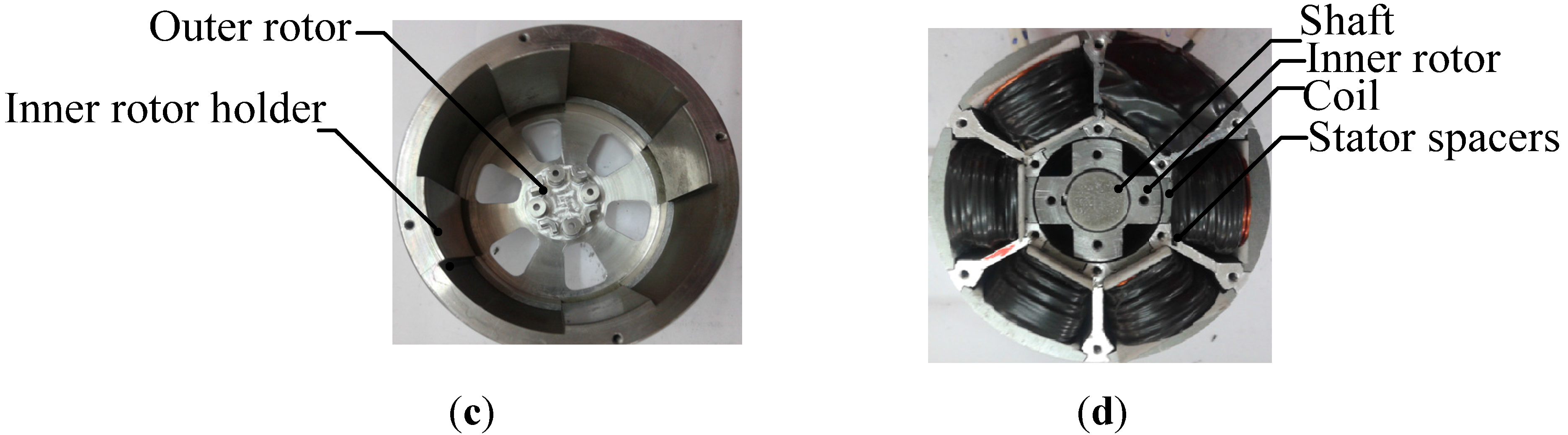
Figure 1 shows the DRSRM configuration that was designed and investigated based on the parameters derived for improvised torque performance [2,11]. The machine comprises a double rotor structure with four poles each with a common axis and a double headed stator with six poles. The inner and outer rotor are located on the interior and exterior of the machine structure, respectively, with a common axis structure. As seen there is a dual air gap (air gap 1 and air gap 2) between the inner and outer rotor surfaces to the surface of the stator pole teeth on either face. The dual air-gap structure introduces two air-gap surfaces thereby reducing the air gap length by half, in comparison to the single air-gap surface in the conventional machine structure. This aids in establishing two magnetic circuits in the magnetic flux path that serve to maximize the flux linkage to increase the torque value reasonably. Table 1 shows the specification of the fabricated DRSRM. In the DRSRM structure, the pole arc at the interaction positions predominantly possesses the energy conversion capability and it is also responsible for the torque ripple generation during the shift of phase excitation in the adjacent poles. Hence, the design of the pole arc on the rotor and stator surface is highly significant for the energy conversion process [12]. Lawrenson [12] proposed a method for a range of pole arc values using a feasibility triangle approach and the choice of the pole arcs in the double rotor is straightforward using this method. The optimization of the choice of the motor in this investigation with respect to maximization of inductance ratio, the effect on the mechanical pull due to the double rotor structure to the common shaft axis is documented in [10].
Figure 1. Double Rotor Switched Reluctance Motor: (a) structural configuration; (b) exploded view of the DRSRM; (c) outer rotor; (d) inner rotor with stator and coils.
Energies 05 04008 g001aEnergies 05 04008 g001b
Table 1. Motor specifications.
ParameterValue
Number of stator poles6
Number of rotor poles4 (dual)
Outer diameter 80 mm
Outer rotor inner diameter 66.6 mm
Air gap length 0.5 mm
Inner rotor outer diameter 51.9 mm
Shaft diameter 7 mm
Stack length (Lstk)40 mm
MaterialSS400
Turns per phase (N)80
Rated current (i)16.33 A
Power 100 W
Torque1.6 N-m
Voltage 80 V
Outer rotor pole arc
Inner rotor pole arc
35 deg
45 deg
Stator inner surface pole arc
Stator outer surface pole arc
30 deg
50 deg

2.2. Energy Conversion from the First Principles

The relational factor of the inductance with respect to the rotor position and phase current of the DRSRM is highly essential for the efficient energy conversion principles. The generated electromagnetic torque and the optimal utilization factor of a DRSRM are commonly determined based on the energy relations. There are two energy factors, involved in the energy conversion process at a particular current excitation value, namely the magnetic field energy Δ W f and the co-energy Δ W c o , as shown in Figure 2a,b. The co-energy Wco available to be converted into mechanical work in each working stroke is equal to the area enclosed by the trajectory of the operating point in the ψ-i diagram. The magnetic field energy Wf corresponds to the stored field energy in the case of a specific rotor position and constant current in the machine. Referring to Figure 2b, the current is established at a rotor position of minimum inductance θon and is held around a reference value by a current controller and the phase is de-energized at the turn-off angle θoff.
Figure 2. Energy conversion principles: (a) Ideal condition; (b) Practical condition.
Energies 05 04008 g002
If T e denotes the developed electromagnetic torque and Δθ represents the change in the rotor position between successive instances then as seen from the Figure 2a:
T e Δ θ = area ( 1 4 3 2 1 ) ( area ( 0 2 3 0 )   area ( 0 1 4 0 )
T e Δ θ = area ( 0 1 2 0 )
T e = area ( 0 1 2 0 ) Δ θ = Δ W Δ θ

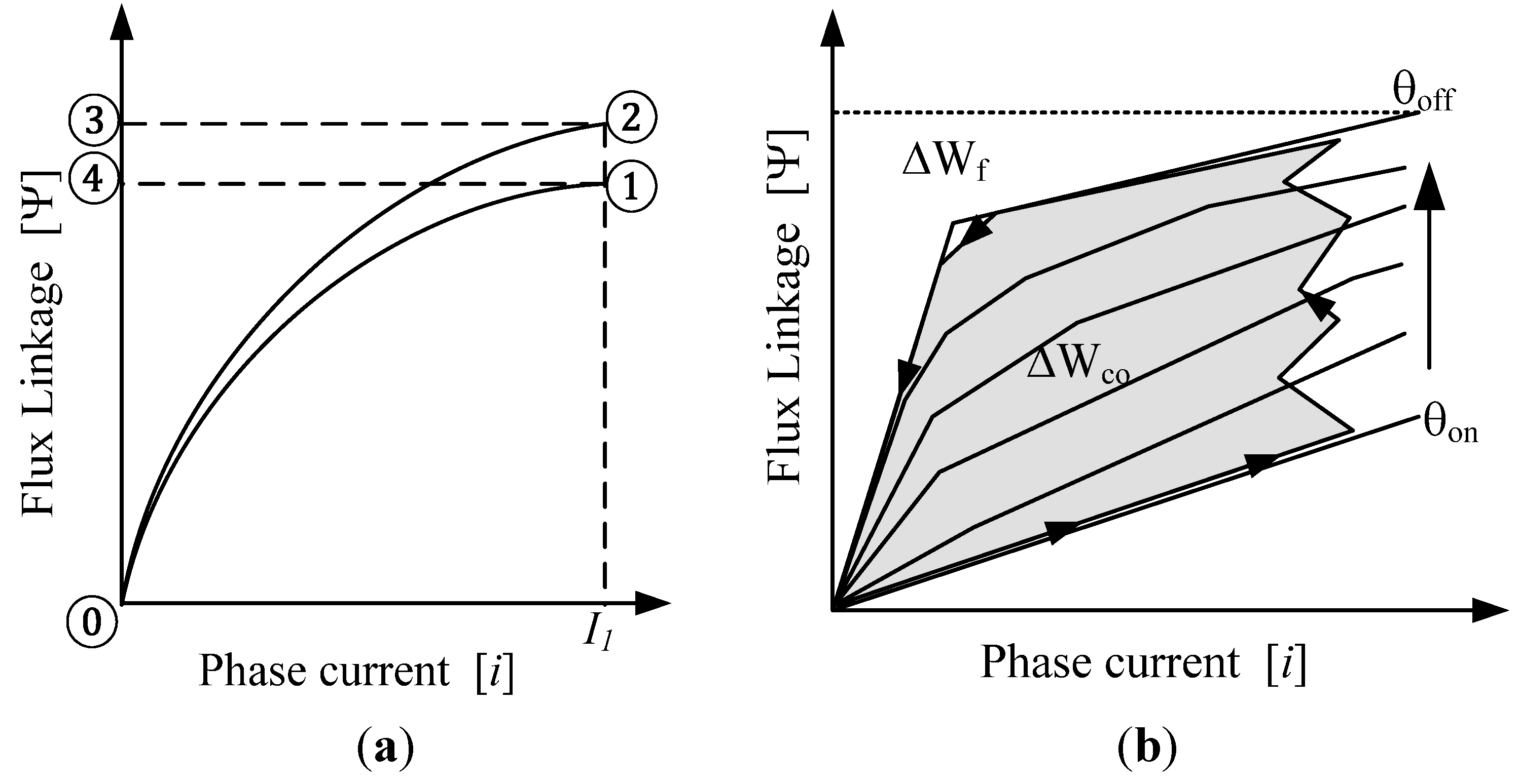
2.3. Inductance Computation Based on Energy Relations

The phase inductance of the DRSRM can be expressed using a Fourier series expression as in Equation (4):
L ( i , θ ) = n = 0 L n ( i ) cos ( n N θ )
where N is the number of rotor poles. Expanding the above equation as in Equation (5):
L ( i , θ ) = L 0 ( i ) + L 1 ( i ) cosn ( N θ ) + L 2 ( i ) cosn ( 2 N θ )
In this analysis three different positions are considered, namely unaligned ( L u ) partially aligned L p 1 (1/4th aligned) and L p 2 (3/4th aligned) and aligned condition ( L a , as seen in Figure 3. From the partially aligned condition the average inductance value is developed for the midpoint alignment ( L p ) . This method of analysis for proposed DRSRM is based on the approach documented in [8].
L a = L 0 + L 1 + L 2   L p = L 0 L 2 L u = L 0 L 1 + L 2 L p = 1 2 ( L p 1 + L p 2 )
The coefficients L o L 1 L 2 can be derived from the above as:
L 0 = 1 2 [ 1 2 ( L a + L u ) + L p ] L 1 = [ ( L a L u ) ] L 2 = 1 2 [ 1 2 ( L a + L u ) L p ]
Figure 3. Calculation positions.
Energies 05 04008 g003
As can be seen from the characteristics the unaligned position is a straight line and the aligned and midpoint can be approximated as an arc tangent function.
The flux linkage is given as Ψ ( i , θ ) = i L ( i , θ ) . The characteristic unaligned flux linkage ( Ψ u ) is considered as straight line hence:
Ψ u = L u i
The aligned and partial aligned characteristics are approximated by an arc tangent function and are represented as in Equations (9) and (10):
Ψ a = tan 1 ( a 1 , i ) a 2
Ψ p 1 = tan 1 ( p 1 , i ) p 2
For finding the values of the constants considering the points Ψ s a and Ψ m a be the values of the flux linkage at two different threshold current values, the constants a 1 a 2 p 1 using curve fitting is given by:
Ψ m a Ψ s a = tan 1 ( a 1 , i m ) tan 1 ( a 1 , i s )
From the above curve fitting equation the Ψ s a is computed, then the constant a 2 is found using the expression below:
a 2 = Ψ s a tan 1 ( a 1 , i s )
Similar to Equations (11) and (12) above, the other constants can be easily derived.

2.4. Voltage Equation Computation

The voltage equation is given as:
V = i R + Ψ i d i d t + ω Ψ θ
where V is the applied voltage, i is current drawn by the machine, Ψ is the flux linkage, ω is the rotational speed, θ is the rotational angle, but: Ψ = Ψ 0 + Ψ 1 cos ( N θ ) + Ψ 2 cos ( 2 N θ ) :
V = i R + Ψ 0 + Ψ 1 cos ( N θ ) + Ψ 2 cos ( 2 N θ ) ] i d i d t + ω Ψ θ
Ψ 0 = 1 2 [ 1 2 ( Ψ a + Ψ u ) + Ψ p ] Ψ 1 = [ ( Ψ a Ψ u ) ] Ψ 2 = 1 2 [ 1 2 ( Ψ a + Ψ u ) Ψ p ]
Differentiating the above and putting into the voltage equation as:
d Ψ 0 d i = 1 4 [ d Ψ a d i + d Ψ u d i ] + 1 2 [ d Ψ m d i ]
d Ψ a d i = [ a 1 a 2 . 1 1 + ( a 1 i ) 2 ] d Ψ u d i = L u d Ψ m d i = [ p 1 p 2 . 1 1 + ( p 1 i ) 2 ]
d Ψ 0 d i = 1 4 [ a 1 a 2 . 1 1 + ( a 1 i ) 2 + L u ] + 1 2 [ p 1 p 2 . 1 1 + ( p 1 i ) 2 ] d Ψ 1 d i = 1 2 [ a 1 a 2 . 1 1 + ( a 1 i ) 2 L u ] d Ψ 2 d i = 1 4 [ a 1 a 2 . 1 1 + ( a 1 i ) 2 + L u ] 1 2 [ p 1 p 2 . 1 1 + ( p 1 i ) 2 ]
Differentiating Equation (15) w.r.t θ :
Ψ θ = N Ψ 1 sin ( N θ ) 2 N Ψ 2 sin ( 2 N θ )
From Equations (9)–(15):
= N 2 [ 2 ( Ψ a Ψ u ) sin N θ + ( Ψ a + Ψ u ) 2 Ψ p ) 2 sin ( 2 N θ ) ]
Therefore the voltage equation is given as:
V = i R + { 1 4 [ a 1 a 2 . 1 1 + ( a 1 i ) 2 + L u ] + ( 1 2 [ p 1 p 2 . 1 1 + ( p 1 i ) 2 ] + 1 2 [ a 1 a 2 . 1 1 + ( a 1 i ) 2 L u ] ) cos ( N θ ) + ( 1 4 [ a 1 a 2 . 1 1 + ( a 1 i ) 2 + L u ] 1 2 [ p 1 p 2 . 1 1 + ( p 1 i ) 2 ] ) cos ( 2 N θ ) } ( d i d t ) + ω { N 2 [ ( tan 1 ( a 1 , i ) a 2 L u i ) sin N θ + ( tan 1 ( a 1 , i ) a 2 L u i 2 tan 1 ( p 1 , i ) p 2 ) sin 2 N θ ] }

2.5. Electromagnetic Torque Equation Computation

The electromagnetic torque is derived as:
T = 0 i [ ( N Ψ 1 sin ( N θ ) 2 N Ψ 2 sin ( 2 N θ ) d i ]
T = 1 2 [ N sin ( N θ ) ] [ 0 i Ψ a d i + 0 i Ψ u d i ] N   sin ( 2 N θ ) [ 1 2 0 i Ψ a d i + 1 2 0 i Ψ u d i 0 i Ψ p d i ]
Energies 05 04008 i001
Energies 05 04008 i002
To optimize the improvement in the electromagnetic torque the proportion of returned energy ∆Wf should be small compared to the conversion energy ∆Wco. Therefore, a large inductance ratio La/Lu is necessary, corresponding to a maximized cross-section area of the magnetisation characteristics ψ(i,Θ) and this is considered when the machine is optimized using the FEA tool [13].

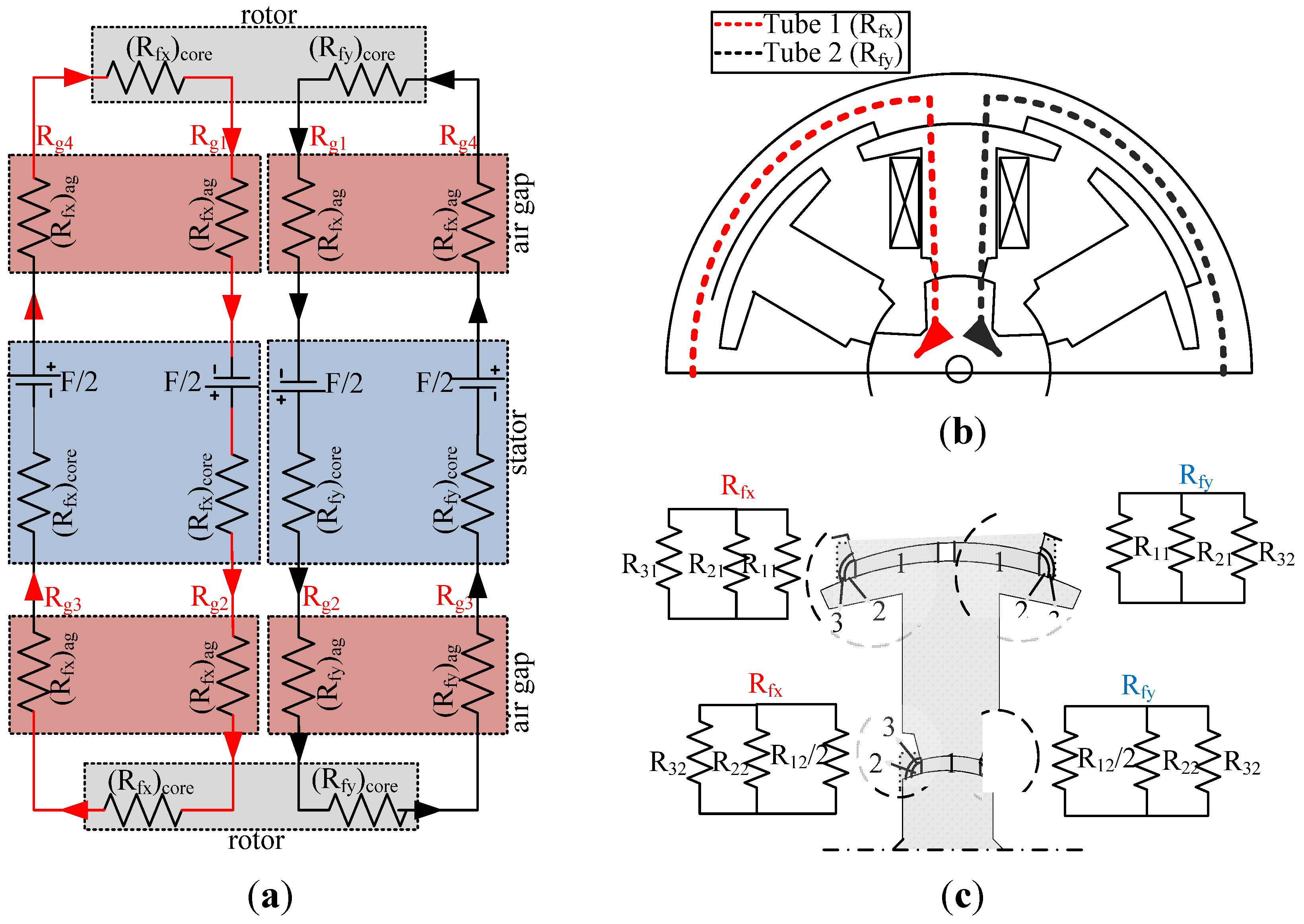
2.6. Equivalent Magnetic Circuit for Analysis

The equivalent magnetic circuit of the double rotor machine as shown in Figure 4 is divided into different magnetic circuit blocks and is configured by series-parallel combinations.
Figure 4. Magnetic circuit network: (a) Flux flow; (b) Reluctance network; (c) Iron core calculations; (d) Airgap calculations; (e) Algorithm used for calculations.
Energies 05 04008 g004
As the stator is excited with the power circuit the flux flow from the stator to the inner rotor yoke through air gap 2 (Rg2), enters the stator in the other face through air gap 3 (Rg3) in the bottom stator pole, moves to the outer yoke through air gap 4 (Rg4) and returns to the excited coil through the airgap1 (Rg1) in the upper stator pole from the outer rotor surface. The machine has two air gaps at the interaction teeth of the outer rotor-stator surface and the inner rotor-stator surface on both sides of the flux flow (Rg1–Rg4). The magnetic circuit considered is long flux flow and hence the reluctance R i n n e r   includes two reluctance circuits ( R g 1 + R g 2 + R s p 1 + R s y +   R s p 2 + R s p 1 + R i r p + 0.5 R i r y ) on the upper surface and ( R g 3 + R g 4 + R g + R s p 1 + R s y +   R s p 2 + R s p 1 + R i r p ) on the lower surface.
With R g 1 = R g 3 and R g 2 = R g 4   the net reluctance is computed as:
R t = R i n n e r   + ( R o r y + R o r p 2 )
  R i n n e r = 2 ( R g 1 + R g 2 + R s p 1 + R s y +   R s p 2 + R s p 1 + R i r p ) + [ ( R i r y ) 2 ]
The flux tube path is chosen based on the position of the rotor with respect to the stator. Two flux tube paths are assumed under unaligned and aligned position with the flux entering the upper part leaving the lower tube exactly on the same side. At any partial aligned computation position the flux tube is assumed as three different paths with flux lines flowing uniformly in the center tube and in the other two tubes the flux entering the upper surface leaves on the opposite side of the lower surface. The surface area of flux linkage of the tubes depends on the rotor position with respect to that of the stator surface at any time instance. Within the flux tube for each of the parts of the machine such as the stator, rotor cores, air-gap etc., a small strip is integrated along the longitudinal axis and then integrated over the surface under considerations from l1 to lm then from r1 to rn as in Figure 4c and Figure 4d for the iron core and the air gap respectively. Figure 4e shows the algorithm used in the computation of the flux tube analysis.

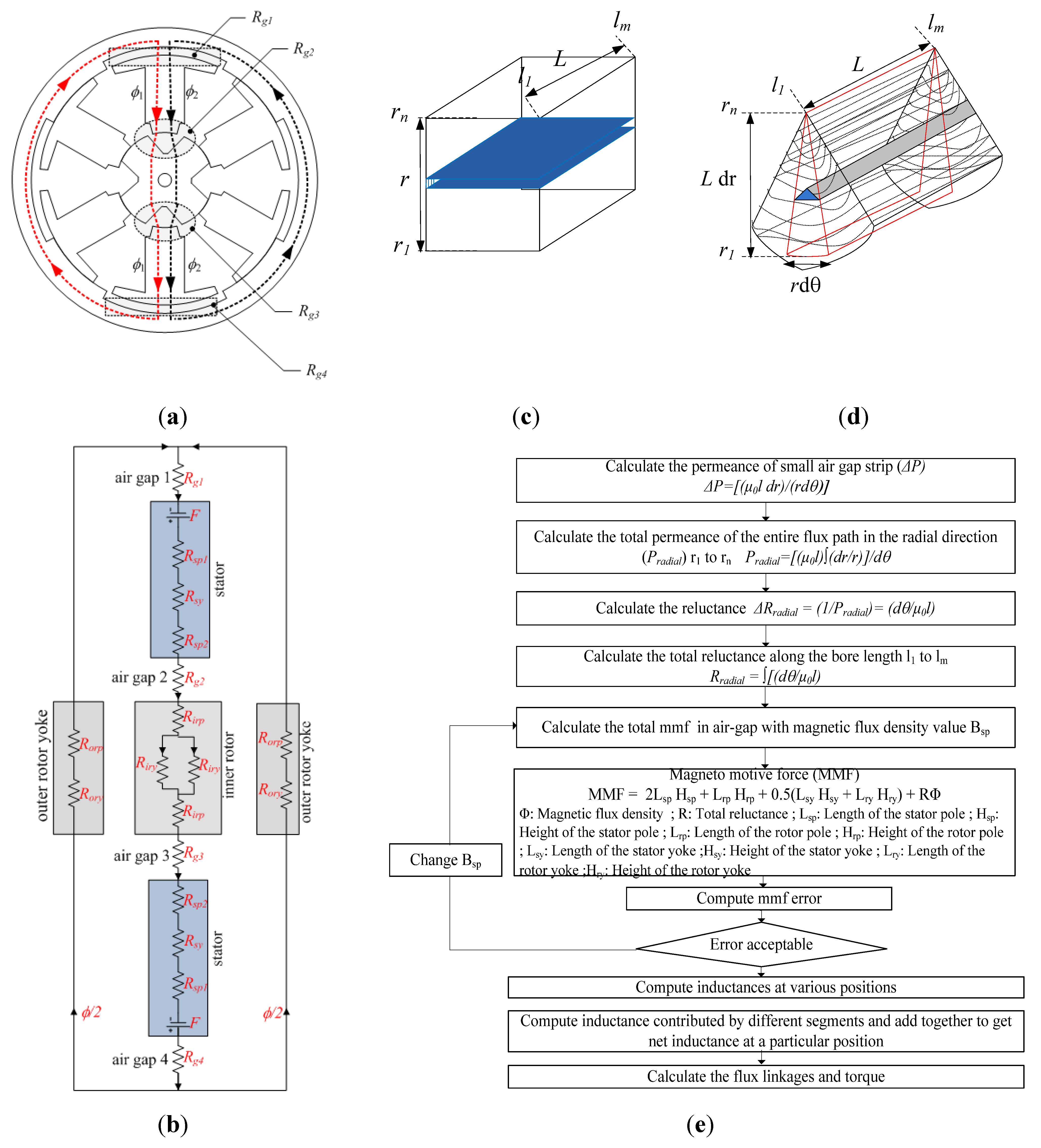
2.6.1. Unaligned Position Computation

The equivalent circuit for the unaligned position is as shown in Figure 5a. In the unaligned position the flux path comprises the flux tubes with the flux pattern converging at the edge of the stator outer pole surface with the rotor pole tip. A similar effect is observed in the flux flow in the opposite surface in the lower pole surface. The fringing flux predominate the flux flow rather than useful flux in this position. As can be inferred the flux diverging is considered symmetric about the y axis. Hence, the calculation of one half of the flux flow is sufficient to compute the net reluctance value.
Figure 5b shows the reluctance values assumed in the air-gap. At this position most of the flux flow is assumed in the air-gap as leakage rather than useful flux. In other words, there is no efficient energy transfer taking place during this period because of the symmetrical structure of the flux in both tubes. The subscript x represents the position of the assumed flux tube depending upon the shape. The values of the variables w m , b m , l m , c depends on the consideration of the area within the shapes. Figure 5c shows the shape with the corresponding permeance Equation (12):
R t = [ ( R f x ) c o r e + ( R f x ) a g ] | | [ ( R f y ) c o r e + ( R f y ) a g ]
where the subscript “ag” represents the air gap.
Figure 5. Reluctance in air-gap at unaligned position: (a) magnetic circuit at unaligned position; (b) reluctance shape assumptions; (c) reluctance shapes under consideration.
Energies 05 04008 g005

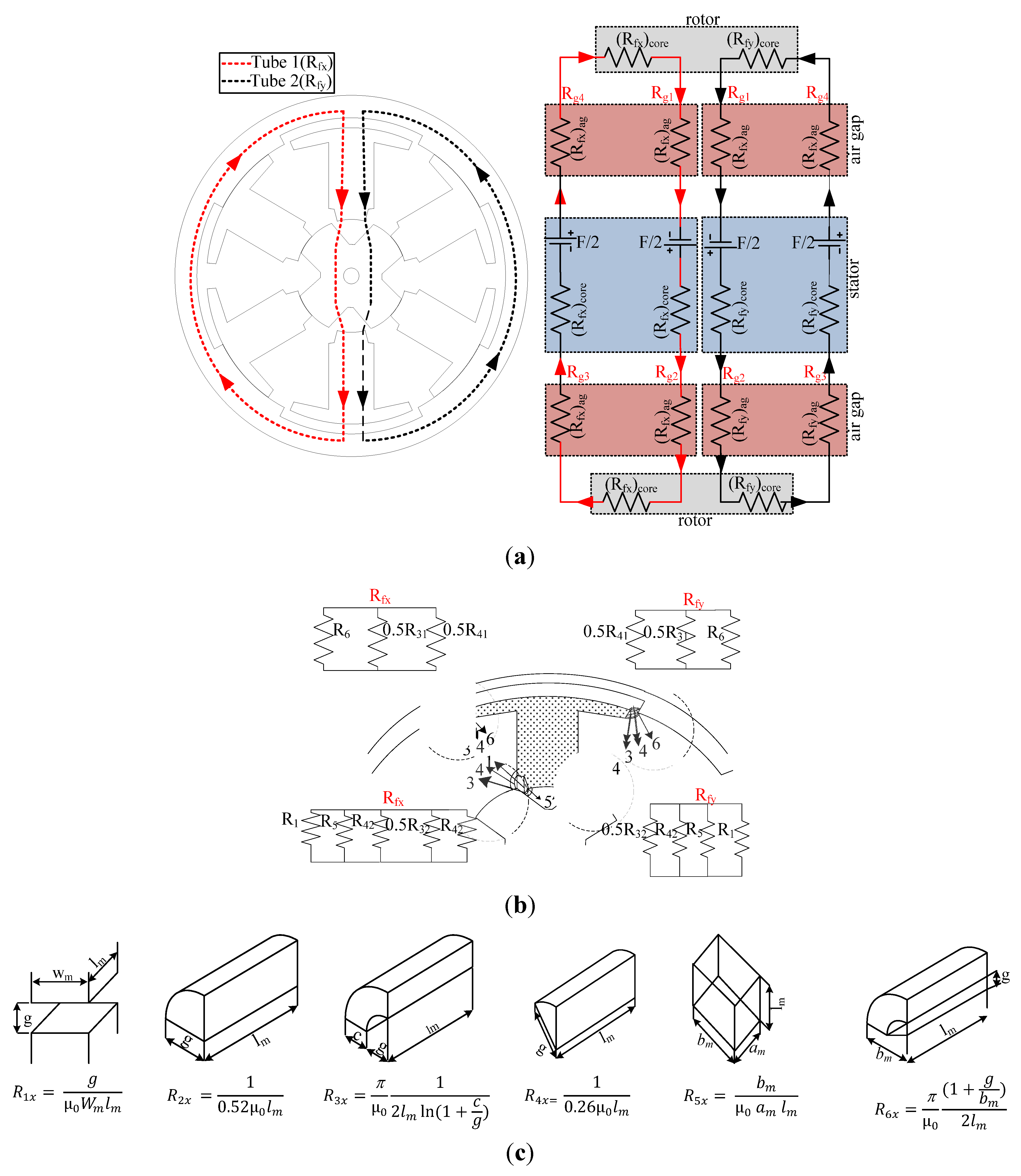
2.6.2. Partial Aligned Computation

In the partially aligned positions the flux spread out is very significant as the flux is converging at the edge of the stator poles. This is the period at which the energy conversion is produced as the rotor rolls over the stator. Hence, the assumptions have to be more accurate to predict accurate results. Figure 6 shows the magnetic equivalent circuit at any intermediate positions.
Figure 6. Analysis during partial-aligned positions: (a) 1/4th aligned flux analysis; (b) 3/4th aligned flux analysis.
Energies 05 04008 g006
As a relevantly higher flux concentration occurs in this case the flux tube regions are classified into three regions, namely Tube 1( R f x ), Tube 2( R f y ) and Tube 3( R f z ). In this case, the flux tube on the top surface R f y would enter as R f x in the bottom surface and vice versa. The center flux tube R f z is assumed to be uniform. In other words, the flux entering the Tube 2 on the right side of the stator should leave from the left side of the tube on the bottom surface. The air gap reluctance is considerably higher compared to that of the core reluctance at this position and hence the computational accuracy of the air-gap reluctance is highly significant. Figure 6a shows the computations for the 1/4th aligned position of pole interactions. Figure 6b shows the network configurations during the 3/4th aligned configuration. It is assumed in this position that the linking flux contributes 1/3rd of the pole arc area of the stator pole. To derive the flux linkage characteristics in any of the positions between the aligned and unaligned condition the surface area at the interaction area is to be determined. The reluctance in these conditions is predominantly due to the air gap and core reluctance is much smaller. Hence, the core reluctance tube is considered with a spread out factor depending upon the ratio of pole arc values of the stator and rotor surface. The air gap reluctance is calculated in a much simpler way as a single unit and divided proportionately using the spread out factor. The net reluctance is calculated as in Equation (29):
R t = [ ( R f x ) c o r e + ( R f x ) a g ] | | [ ( R f y ) c o r e + ( R f y ) a g ] | | [ ( R f z ) c o r e + ( R f z ) a g ]
where the subscript “ag” represents the air gap.

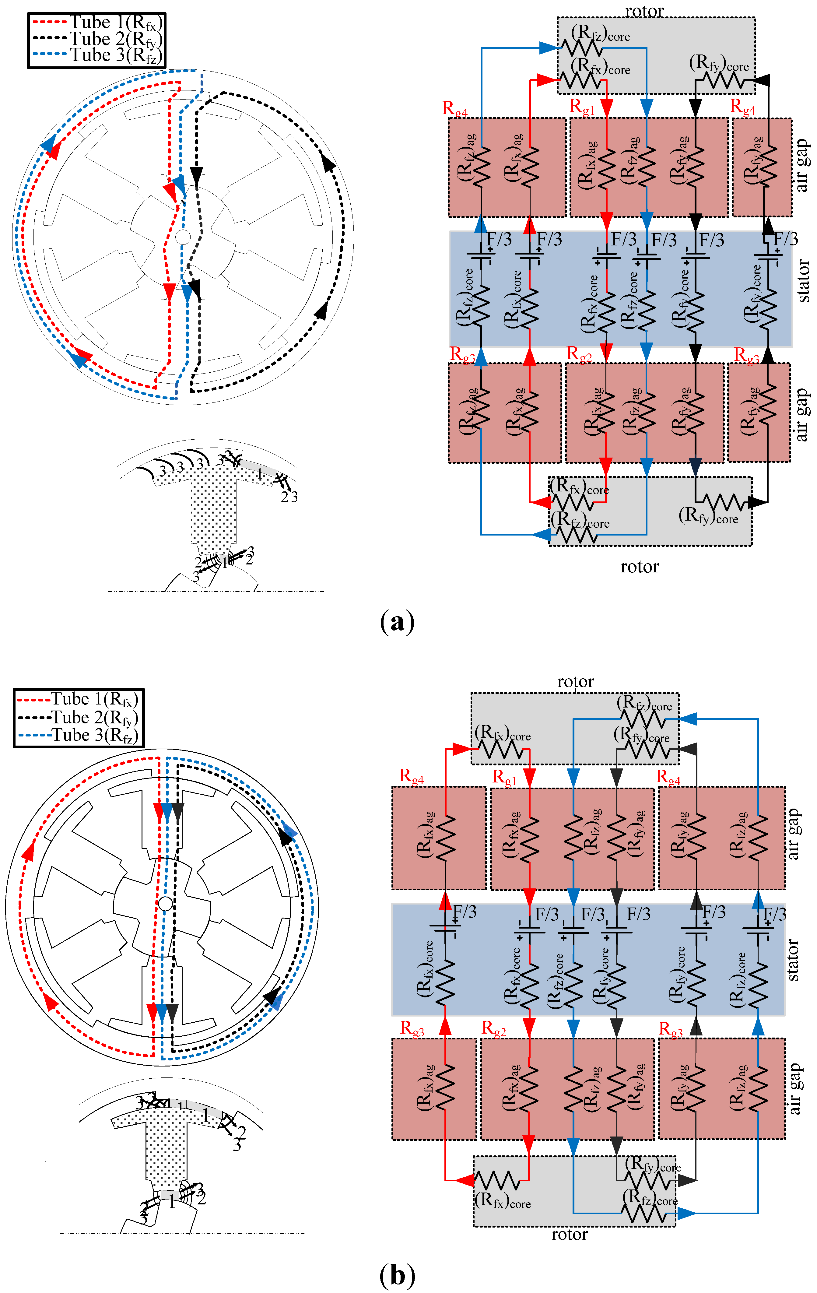
2.6.3. Aligned Position Computation

Figure 7 shows the flux flow in the aligned positions of the stator and rotor. The flux flow is uniform, except at the spreading out area close to the alignment of the teeth of the stator and the rotor. The flux is expected to diverge at the outer pole interaction surface and converge at the inner pole tooth interaction. The flux tube is equal on both the surface and hence core reluctance is significant at this position. The reluctance paths   R f x and R f y shows the magnetic flux flow with one phase excitation. The air gap R g 1 is the air-gap between the outer rotor core and the stator and R g 2 represents the airgap between the inner rotor and the stator. The air-gap reluctances R g 3 and R g 4 form the airgap in the other side of the magnetic circuit and help complete the magnetic circuit:
R t = [ ( R f x ) c o r e + ( R f x ) a g ] | | [ ( R f y ) c o r e + ( R f y ) a g ]
Figure 7b shows the flux flow in the air-gap interacting surfaces as R g 1 and R g 2 (path in the air gap in the outer and inner air-gap interactions). The increase of aligned area due to a larger interaction surface area maximizes the flux linkage and reduces the reluctance value. The main reluctance is R 1 x in the air gap R g 1 and in the air gap R g 2 . The fringing flux comprises the shape including R 2 x and   R 3 x . In the air gap R g 2 the flux flow is uniform, hence it can be considered half. Based on the above shape considerations, the net reluctance in the air gap is computed as follows:
( R f x ) a i r g a p = 2 ( R 31 | | R 21 | | R 11 ) + 2 ( R 32 | | R 22 | | 0.5   R 12 )
( R f y ) a i r g a p = 2 ( R 31 | | R 21 | | R 11 ) + 2 ( R 32 | | R 22 | | 0.5   R 12 )
In order to calculate the value at any intermediate positions the surface of the flux interactions and that of the magnetic flux density with respect to the rotor position is developed based on the area of flux interactions to the size of the air-gap surface area. The computation of the flux paths at different tube surfaces are calculated using a computational program employing the mathematical expression with correction coefficients. The individual reluctance values at various parts in the magnetic flux path are computed. By series-parallel configuration of the magnetic flux flow inside machine the net reluctance at one position is calculated. The reluctance of the core depends on the area of the surface and the length of flux flow assumptions. Once the reluctance R t is computed, then the magnetic flux is calculated using Equation (33):
Φ = M M F R t
where MMF is the magnetomotive force and Φ is the magnetic flux The flux linkage is then computed for the known number of turns N value using Equation (5):
  Ψ ( i , θ ) = N Φ   ( i , θ )
where Ψ being the flux linkage. The inductance is then calculated for that position using Equation (6):
L ( i , θ ) = Ψ ( i , θ )   i
Figure 7. Flux flow representation during aligned position: (a) Magnetic Circuit; (b) Flux flow; (c) Air-gap reluctance.
Energies 05 04008 g007
The computation of the characteristics is straightforward. By the accurate prediction of the inductance at different positions the machine can be operated with maximum efficiency [11]. Hence the analytical derivation of the electrical parameter at intermediate positions is highly significant. Once the inductance at various positions is computed, the mechanical characteristics are then derived using Equation (25).

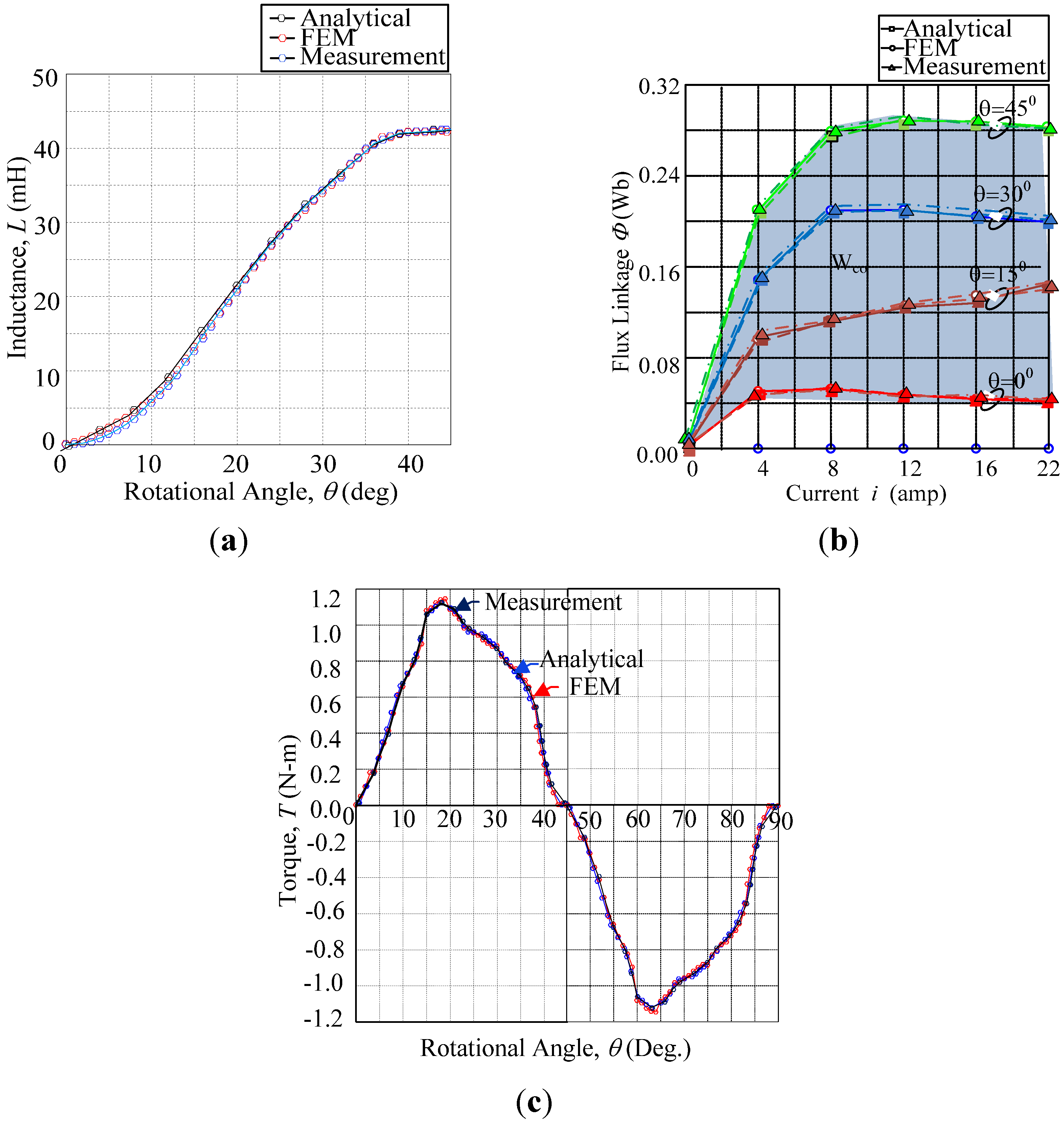
3. Comparative Evaluations
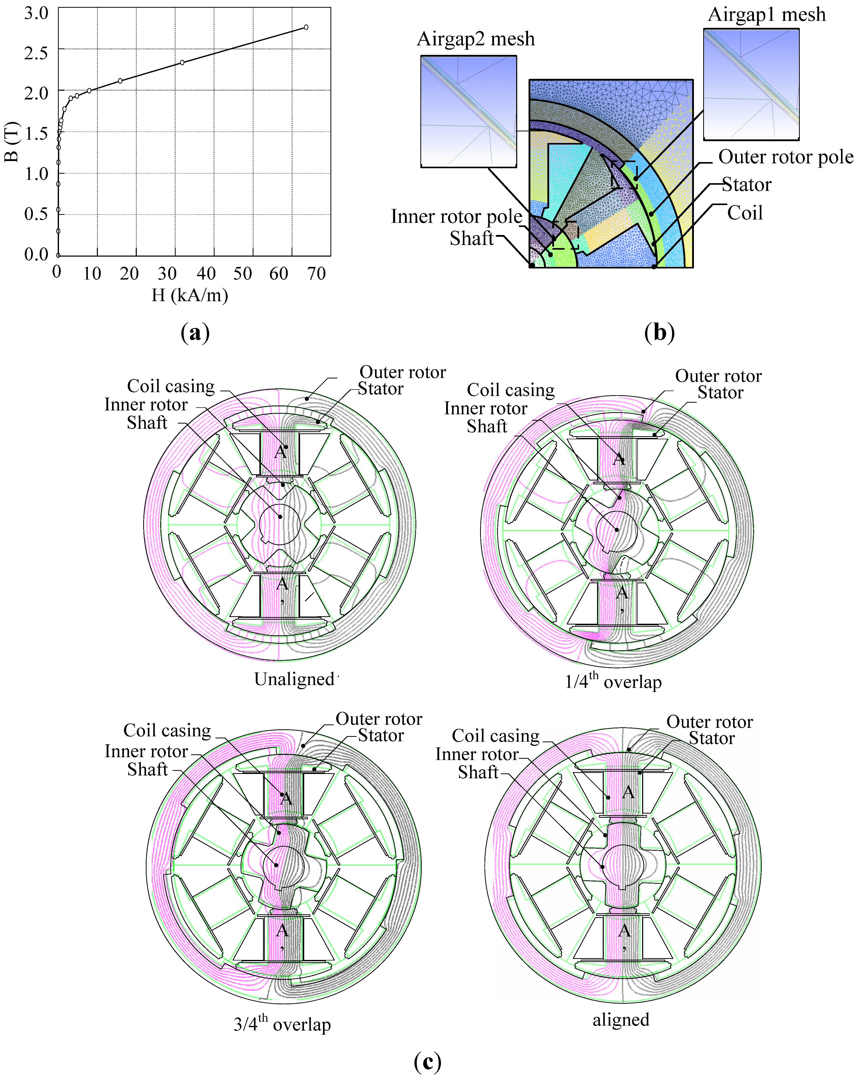
3.1. FEM Simulation

To verify the proposed analytical method and to validate the machine structure Finite Element Analysis was carried out. The FEA tool used in this investigation is developed based on the nodal force method. This method is similar to the method of finding an equivalent nodal force from distributed load force load in stress analysis [14]. From the FEM simulation, the path of flux flow, magnetic flux density, the torque characteristics, and the inductance value is derived. Figure 8a shows the BH curve of the material used in the FEM calculations and the element discretization in the FEM is as shown in Figure 8b.
Figure 8. FEM flux flow pattern (a) BH curve for the material used; (b) FEM Discretization; (c) Flux flow at different aligned positions.
Energies 05 04008 g008
In order to make the FEM calculations more accurate six circular tubes are used in the air-gap surface. As can be seen during the aligned and unaligned condition the flux flow is uniform on both the sides of the core. During the partial overflow the flux pattern entering the right side of the upper pole surface is leaving the left side of the lower pole as assumed in the analytical derivation of the flux tube. However, little leakage fluxes towards the movement of the rotor in the unaligned condition that is less significant. The flux flow simulation results follow the assumptions made in the analytical computations.

3.2. Experimental Evaluation

A machine with the proposed dimensions was fabricated and experimentally tested with an incremental load value and for each position the mechanical characteristics are captured. The block diagram representation of the experimental setup for the incremental loading test and the experimental setup for the measurement of static characteristics is as shown in Figure 9a,b, respectively. For fixing the rotor in one position a mechanical brake with an incremental encoder is attached to the motor unit. A torque sensor module to capture the instantaneous torque is also attached to the common shaft with a machine coupler. The mechanical loading test is incrementally moved using a gear arrangement and the rotor position with that of the torque measurements are recorded for both clockwise and anti-clockwise rotation. Measurements are received from the DAQ system and a program written in LabVIEW software. A constant DC source is used and the above procedure is implemented to capture the data in real time. The experiments are performed for different current values. All the measurement data are saved in the computer through the Tektronix toolbox interface. The actual values are then derived from the captured value by mathematical analysis. From the mechanical characteristics the magnetic characteristics are derived by mathematical formulations using mathematical tools.
Figure 9. Experimental evaluations: (a) Block diagram of setup; (b) Experimental setup.
Energies 05 04008 g009

4. Results and Discussion

The analytical computation based on the proposed method is performed for different rotor positions and the exact interpretations of the values are used to compute the energy value and thereby the torque generation inside the machine. As the machine has a single excited energy source the interpretation of the flux lines yields good results. However for the accuracy of the prediction in a dual source machine the challenge lies in the use of a higher number of flux flow tubes assumption. The inductance value is computed at different rotor positions from fully unaligned, to aligned including the partially aligned (at 1/4th aligned and 3/4th aligned) positions using FEM and the incremental inductance method. The flux lines from the FEA significantly follow closely the assumptions of the flux tube made in the analytical computation procedure with minimal errors. A comparison of the inductance profile of the analytical method with that of the simulation and measurement results is shown in Figure 10a. Figure 10b shows the torque profile comparisons for a half rotor pole pitch. The maximum torque generated by the measurement is about 1.13 N-m and by simulation it is 1.17 N-m, whereas by the proposed method the maximum torque value is about 1.12 N-m. However the average torques for the three methods give closer values. Figure 10c shows the comparison values on the computation of the flux linkages at different rotor positions and for different currents. The plot is derived by variation of the current value of the simulation, measurement over the half pole pitch and is compared with the analytical values. It is inferred that from the plot that the computation results by the analytical method are closer to the FEA tool that employs the nodal force method. The analytical results are also compared with the experimental results for validation. The average torque by the proposed analytical computation is 0.947 N-m, from the FEM it is found to be 0.953 N-m and by measurement it is about 0.949 N-m. Table 2 summarizes the results derived from the analytical and FEM methods and measurements. The computation time involved for the proposed method takes less time compared to that of the FEM simulation, which takes approximately 1 min for each rotor position.
Figure 10. Inductance profile comparison of analytical method evaluations: (a) inductance characteristics; (b) flux linkage characteristics; (c) torque characteristics.
Energies 05 04008 g010
Table 2. Comparative evaluations.
Computation MethodInductance (mH)Tavg (N-m)
unaligned1/4th aligned3/4th alignedaligned
Analytical3.9620.3630.4035.90.947
FEM4.0120.1530.4335.70.953
Measurement3.9820.3830.3836.30.949

5. Conclusions

An analytical method for accurately calculating the magnetic and mechanical characteristics for different rotor positions of a double rotor structure reluctance motor using flux tube methods is presented. The magnetic energy flow assumed in this analysis is the long flux flow, wherein the opposite stator pole is excited with pulse circuits. The flux path is categorized as three parallel tubes with the end flux tubes interchanging the flux pattern at the other end of the stator pole with the center flux tube having a uniform flux flow for any intermediate position. For both the unaligned and aligned conditions the flux tube is uniformly divided into two flux tubes. The flux linkage is computed based on the division of the reluctance in different parts of the machine core, in the air gap and the net reluctance is computed by the circuit reduction. The magnetic circuit elements, namely the inductance, and flux linkage are derived from the energy conversion loop. The electromagnetic torque is derived from the co-energy equations. The computation procedure presented in this work is faster and exhibits characteristics closer to that of the FEM results. Further the results of the analytical method are compared with the experimental measurement results. Accurate flux linkage computations can be performed with the proposed approach and this is helpful in designing the controller at a later stage of the design. This proposed method can also be extended to the prediction of the energy analysis for any electrical machine.

References

  1. Miller, T.J.E. Switched Reluctance Motors and Their Control; Magna Physic and Clarendon Press: Oxford, UK, 1993. [Google Scholar]
  2. Aravind, C.V.; Norhisam, M.; Aris, I.; Marhabhan, M.H.; Ahmad, D. Double Rotor Switched Reluctance Motors: Fundamentals and Magnetic Circuit Analysis. In Proceedings of the IEEE Student Conference on Research and Development (SCORED2011), Cyberjaya, Malaysia, 19–20 December 2011.
  3. Norhisam, M.; Norafiza, M.; Syafiq, M.; Aris, I.; Nirei, M.; Wakiwaka, H.; Abdul Razak, J. Design and Analysis of Slot Type Embedded Permanent Magnet Generator. J. Ind. Technol. 2009, 18, 1–14. [Google Scholar]
  4. Norhisam, M.; Norafiza, M.; Syafiq, M.; Aris, I.; Nirei, M.; Wakiwaka, H.; Abdul Razak, J. Comparison on Performance of Two Types Permanent Magnet Generator. J. Jpn. Soc. Electromagn. Mech. 2009, 17, S73–S76. [Google Scholar]
  5. Norhisam, M.; Alias, K.; Firdaus, R.N.; Mahmod, S.; Mariun, N.; Abdul Razak, J. Comparison of Thrust Characteristics of Linear Oscillatory Actuators. In Proceedings of the IEEE 1st International Power and Energy Conference (PECon '06), Putra Jaya, Malaysia, 28–29 November 2006; pp. 470–475.
  6. Norhisam, M.; Syafiq, M.; Syafiq, I.; Abdul, R.J. Design and analysis of a single phase slot-less permanent magnet generator. In Proceedings of the IEEE 2nd International Power and Energy Conference (PECon '08), Johor Bahru, Malaysia, 1–3 December 2008; pp. 1082–1085.
  7. Radun, A. Analytically computing the flux linked by a switched reluctance motor phase when the stator and rotor poles overlap. IEEE Trans. Magn. 2000, 36, 1996–2003. [Google Scholar] [CrossRef]
  8. Kokernak, J.M.; Torrey, D.A. Magnetic circuit model for the mutually coupled switched-reluctance machine. IEEE Trans. Magn. 2000, 36, 500–507. [Google Scholar] [CrossRef]
  9. Lin, D.; Zhou, P.; Stanton, S.; Cendes, Z.J. An analytical circuit model of switched reluctance motors. IEEE Trans. Magn. 2009, 45, 5368–5374. [Google Scholar] [CrossRef]
  10. Chi, H.P.; Lin, R.L.; Chen, J.F. A simplified Flux linkage model for Switched Reluctance Motors. IEE Proc. Elect. Power Appl. 2005, 152, 577–583. [Google Scholar] [CrossRef]
  11. Aravind, C.V.; Norhisam, M.; Aris, I.; Marhabhan, M.H. Analytical design of the double rotor switched reluctance motor with optimal pole arc values. Int. Rev. Electr. Eng. 2012, 7, 3314–3324. [Google Scholar]
  12. Lawrenson, P.J.; Stephenson, J.M.; Blenkinsop, P.T.; Corda, J.; Fulton, N.N. Variable-speed switched reluctance motors. Proc. Inst. Electr. Eng. 1980, 127, 253–265. [Google Scholar]
  13. Kameari, A. Local force calculation in 3D FEM with edge elements. Int. J. Appl. Electromagn. Mater. 1993, 3, 231–240. [Google Scholar]
  14. Gieras, J.F.; Wing, M. Permanent Magnet Motor Technology, 2nd ed.; Marcel Dekker, Inc.: New York, NY, USA, 2002. [Google Scholar]

