1. Introduction
In the last years, the impact of human factors on climate change undoubtedly forced the scientific community to focus on renewable energy systems, especially those known with the name of Energy Harvesting Devices (EHDs) [
1], since these represent the only way of maintaining our life standards (e.g., the energy consumption level) without depleting our non-renewable sources (carbon and fossils in general, whose use is in the mean time the first cause of anthropogenic climate change). Thus, it becomes mandatory to exploit all the possible alternative energy sources that may be available from the environment. When we think about “energy from environment” we are used to think and at the same time to limit our attention to natural environment, but we rarely consider the environment where we spend the most of our time, namely our city. Our cities are very hard to model as natural environment, since they are the place where the impact of anthropogenic factors is stronger and definitively not negligible, and this represents exactly the place with the largest energy concentration, where energy is seldom produced but certainly used and sometimes wasted. This is the reason why, thinking about how to exploit the energy harvesting principles, we have to consider urban environment as well, since this environment is hugely energy intensive.
Among all the energy related human activities we can consider in urban environment, traffic is one of the most energy-expensive ones, and, furthermore, it is characterized by great waste: only
of the fuel potential is used to transfer kinetic energy to the vehicle and the largest part of this energy is dissipated in decelerating phases by brakes and gases [
2]. “Powerbumps” are innovative energy harvesting devices that reduce the speed of vehicles by converting the kinetic energy otherwise wasted by brakes into electricity. For obvious reasons of energy balance, those devices cannot be installed randomly on the road network but should be implemented in decelerating sites only, such as urban road crossings, pedestrian crossings, main road exits, where the standard passive speed bumps are usually installed. Whenever this condition is verified, powerbumps allow to achieve the optimal combination of improved road safety and the
compensation of road traffic.
Unfortunately, the design of such a system is absolutely hard, since it requires an integrated approach for effectively facing all the different requirements of energy scavenging. The amount of retrievable energy is typically small and in any case with a high variability in time. In this context, it is interesting to develop suitable techniques for modelling and optimization of renewable energy system design in which it is important not only to recover the maximum amount of energy from different sources, but also to increase overall system efficiency supporting network operators’ planning and operations [
3]. Moreover, the challenge for the next generation EHDs will be to interact with the power grid using smart and dynamic control in order to extract the maximum power, without compromising the quality of the output power.
The technology progresses made over the last few decades in size and power consumption reduction of CMOS circuitry has stimulated the researchers to increase their efforts towards energy-harvesting devices especially for applications in industrial electronics and wireless sensors [
4,
5]. A large number of vibration-based EHDs have been proposed using various mechanisms, including electromagnetic, electro-static, and piezoelectric [
6,
7]. Among them, piezoelectric EHDs have received more attention due to their self-contained power generation capability, but higher power quantities are just promised for the near future by means of optimized design and improved materials.
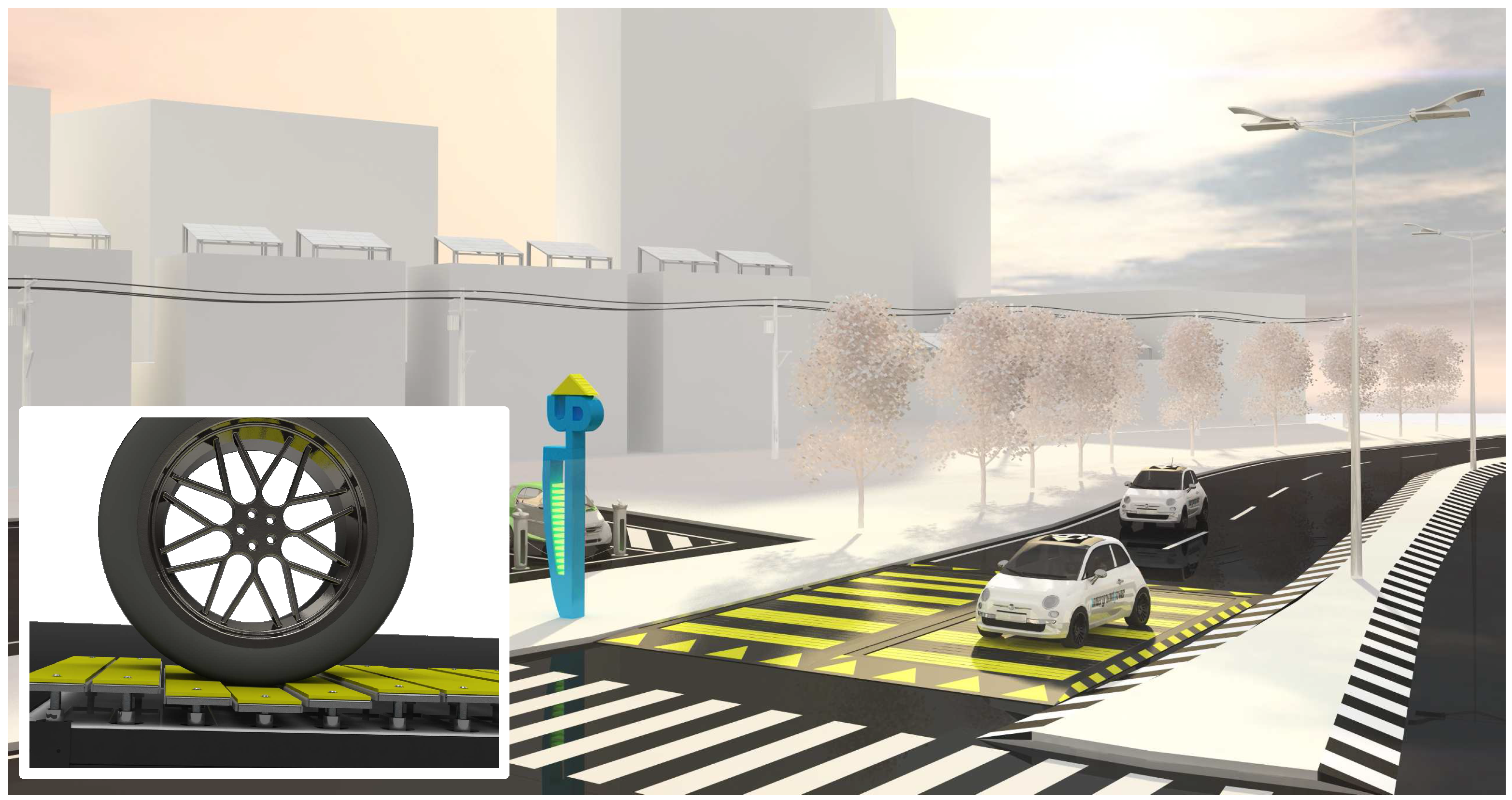
In this paper some investigations have been conducted to apply this kind of devices for recovering energy from traffic, as shown in
Figure 1. Very few attempts in this field exist in literature, for example with piezoelectrics [
8] and hydraulic systems [
9], but here the authors focused on a completely different device, namely a speed bump system. Moreover, other pedestrian safety studies have seen challenging experiments and braking devices tested in complex urban environments, such as in [
10,
11].
Figure 1.
Future scenario of vehicles’ energy harvesting system in Smart Cities (inset: simplified diagram of a speed-bumper energy converter with Tubular Permanent Magnet-Linear Generator).
Figure 1.
Future scenario of vehicles’ energy harvesting system in Smart Cities (inset: simplified diagram of a speed-bumper energy converter with Tubular Permanent Magnet-Linear Generator).
Power bumps are innovative energy harvesting devices similar to flat speed bumps but recover the energy wasted by vehicle brakes in decelerating lanes. They reduce speed, produce electric energy [
12] and increase road safety at the same time.
In our view, the replacement of hydraulic pumps and mechanical flywheel with a tubular generator and dynamic power control would increase the efficiency of the system by drastically reducing the vulnerability due to faults and damages, since no mechanical transmission is used in tubular generators.
Linear generators are today increasingly used for energy conversion, since many natural energy sources exhibit alternating motion [
13]. In fact, renewables are often characterized by presenting discontinuous phenomena without very dense energy content. Moreover, a similar technology has been recently proposed in several marine applications as a well-suited device for wave energy harvesting [
14,
15].
Some other aspects such as active filtering, phase balancing and harmonic cancellation can be critical for the grid voltage stability, and these concurrent desiderata require the study of ad-hoc techniques to fully meet the design criteria for the optimization of such complex systems, which are characterized by a dynamic response with random nature that cannot provide the required continuity. Hence, the aim of this work is to apply advanced soft computing techniques to optimize this kind of EHD for proper design, in order to guarantee the best efficiency of the generating system and to increase its lifetime.
This research moved its first steps in the field of direct-drive linear machines [
16], and now aims to introduce a novel modeling design technique to optimize a tubular linear generator used to recover energy from car vehicles, as exemplified in
Figure 1. A Tubular Permanent Magnet Linear Generator (TPM-LiG) is an electromechanical device able to convert linear motion in electrical energy when driven by a prime mover without any mechanical gearbox. In this case, the optimization is required in order to obtain a voltage waveform close to the square wave to maximize the energy transfer.
The optimization design process with algorithm characteristics and specific implementation scheme are reported in
Section 2.
Section 3 describes the linear generator system with the relative numerical model. Finally
Section 4 illustrates the setup of the experimental bench test (4.1), and the experimental results on system electromotive power output are reported in
Section 4.2.
2. Novel Energy Harvesting System Design
The aim of this work is to achieve a new methodological approach to analyze the dynamics of subsystems for EHDs. In particular, authors have deepened their research on the inverse characterization and direct synthesis of the considered subsystems, integrating these two techniques in a novel procedure that enables to realize the complete design of energy harvesting systems (EHSs) by using an automated computer procedure in few machine hours.
In order to define such design process, a suitable optimization procedure must be considered. In fact, in this case the use of a direct synthesis approach can be very difficult, due to the complexity of the structure and the relevant number of parameters to be determined in order to obtain the requested particular features.
The implementation of computational intelligence techniques for automatic design in the field of transportation has been already used for example for controller structures [
17] and also in electromagnetic system suspension without mechanical contact [
18].
To provide an effective and timesaving modeling of complex systems, here an appropriate combination of evolutionary techniques can be applied as a convenient means towards EHD global design and performance optimization.
2.1. Computational Intelligence for Transportation Systems
The general aim of optimization is to find a solution that represents a global maximum/minimum in a properly defined domain, in other words, to find the best solution among all the possible ones. Industrial design and engineering problems generally involve a large number of physical and geometric parameters that can be both continuous and discrete, and often constrained in their allowable values.
Traditional optimization approaches are often Newton-based methods or, in any case, related to gradient descent algorithms. These techniques, better known as local optimization algorithms, generally need to compute many derivatives for the optimization of the objective function. Considering the large number of variables and the possible presence of local optima, it is generally difficult to use these traditional optimization methods to find the global best solution of complex engineering problems.
Evolutionary techniques have been effectively used in energy applications both for renewable energy optimization [
19,
20] and energy harvesting multi-objective design [
21]. Even in intelligent transportation systems (ITS) applications, these techniques have been used for example to choose the optimal cooperative strategy in terms of energy consumption for road infrastructure networks [
22].
These procedures can overcome those drawbacks, since they are able to find a global optimum, without being trapped in local optima and to face nonlinear and discontinuous problems with a great number of variables [
23]. In fact, evolutionary algorithms apply an indirect synthesis by randomly choosing the parameters of interest and evolving their values towards an optimal solution. This means that one can control several parameters of the design, through a properly defined fitness function that puts constrains, e.g., on the resulting configuration and performances.
Among the main evolutionary optimization approaches, the Genetic Algorithm (GA) [
19,
24] and the Particle Swarm Optimization (PSO) [
20] are worth mentioning.
In GA, each individual of the population encodes the parameters to be optimized, and therefore it represents a possible solution to the problem. For each individual, a fitness function is therefore evaluated and a score is assigned. GA simulates the natural evolution, adopting pseudo-biological operators such as selection, crossover and mutation to improve the fitness score associated to each individual [
25].
In the PSO model, the position of each particle represents a solution of the problem. Particles move in the domain of the problem attracted by both the position of their best past performance and the position of the global best performance of the whole swarm [
26].
These algorithms are iterative techniques with strong stochastic bases and consequently their performances are evaluated in terms of speed of convergence. The use of these techniques, requiring a relevant number of fitness function evaluations, needs particular care if, as in the considered case, the cost function is computationally expensive. Therefore, these approaches must guarantee the exploration of the solution domain to avoid premature convergence to local optima and the exploitation of the results to concentrate the search effort and to reduce the number of requested fitness function evaluations.
Moreover, optimization tools require a significant amount of time and computations, in particular when the device structure is complex, with hundreds or thousands of parameters to be optimized. For this reason, it is often necessary to introduce approximate models, in which the relationship between the physical parameters and the energy performances is derived from heavy numerical simulation.
2.2. Automated Design Procedure
The new technique here applied is based on two of the most known evolutionary optimization approaches GA and PSO. While PSO seems to have a convergence rate faster than GA early in the run, it is often outperformed by GA for long simulation runs, when the last one finds a better solution.
In order to maximize the efficiency of these two techniques, a hybrid technique was developed and named Genetic Swarm Optimization (GSO), since it involves GA and PSO techniques. Its basic concepts have been presented in [
27]: in every iteration the population is randomly divided into two parts, which are evolved with GA and PSO operators respectively. The fitness of the newly generated individuals is evaluated and they are recombined in the updated population, which is again divided into two parts in the next iteration for the next run of genetic, or particle swarm operators.
The driving parameter of GSO algorithm is the hybridization coefficient
, which indicates the percentage amount of population that is processed by GA operators in each iteration
i. The different rules of variation of
during iterations identify several “flavors” in the class of GSO algorithms, as shown again in [
27]. Moreover, the authors proposed also two different adaptive rules, namely dynamic and self-adaptive, in order to combine in the most effective way the properties of the GA and the PSO approaches also for unknown problems. In particular, the proposed method has been tested and validated here on a benchmark magnetic case called
TEAM 25 problem [
28], as shown in [
29].
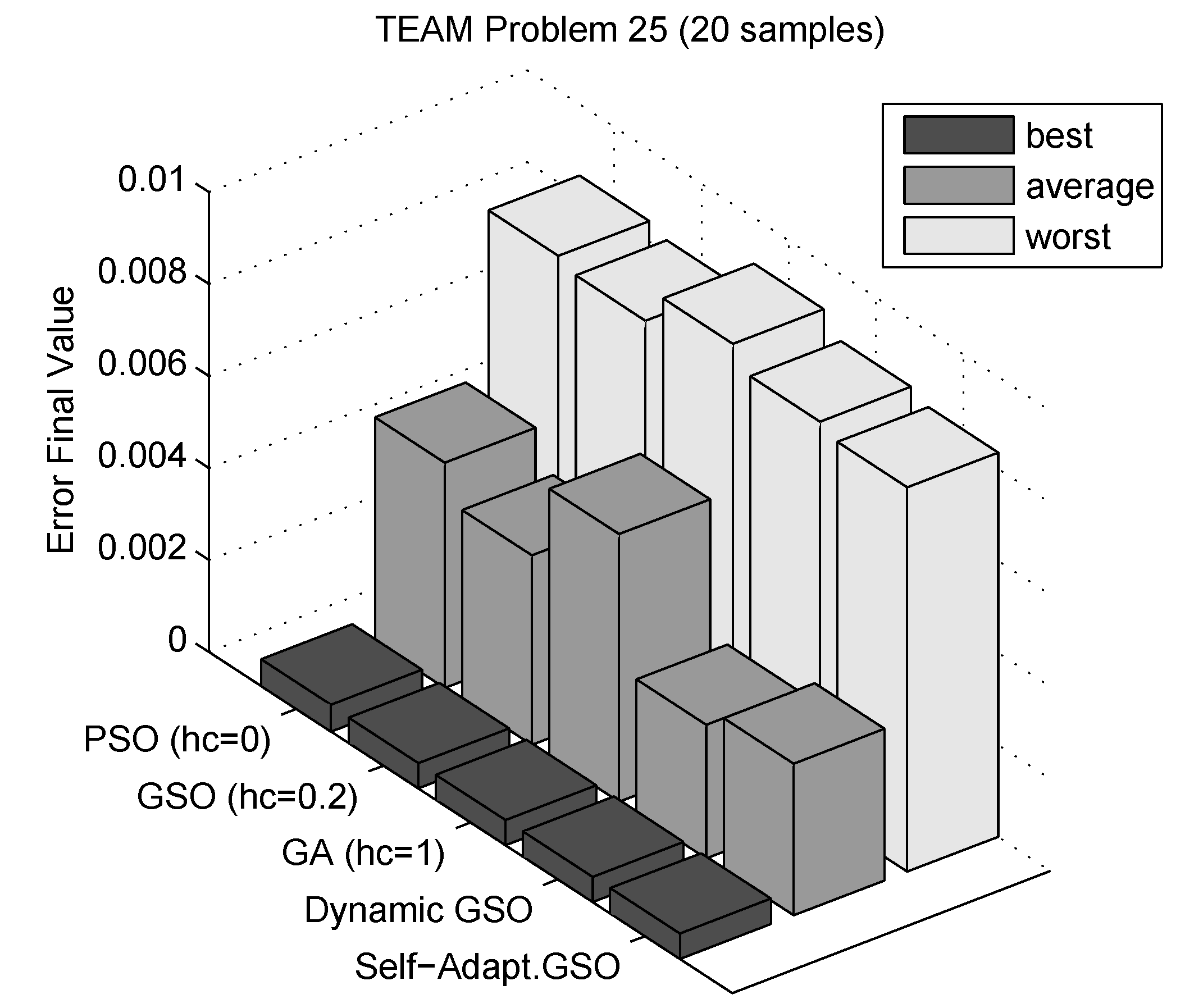
Results of the algorithm performance analysis are reported in
Figure 2. The bars show the best, worst and average performance of the optimization algorithm for a fixed number of iterations and over a given number of independent trials. It is clear from these results that the adaptive strategies perform better even than GA and PSO. The average cost function values found during iterations are reported in
Figure 3, showing a faster speed of convergence of the considered GSO implementations compared with the GA and the PSO.
Figure 2.
Final fitness values for TEAM problem 25 optimized with different GSO hybridization strategies (from [
29]).
Figure 2.
Final fitness values for TEAM problem 25 optimized with different GSO hybridization strategies (from [
29]).
Figure 3.
Fitness value evolution for TEAM problem 25 optimized with different GSO hybridization strategies (from [
29]).
Figure 3.
Fitness value evolution for TEAM problem 25 optimized with different GSO hybridization strategies (from [
29]).
From the overall results reported here and in cited papers, GSO has been chosen as the optimization engine of the automated design procedure of TPM-LiG presented in this paper, according to the fitness function that has been suitably defined and will be described in the following.
2.3. Implementation
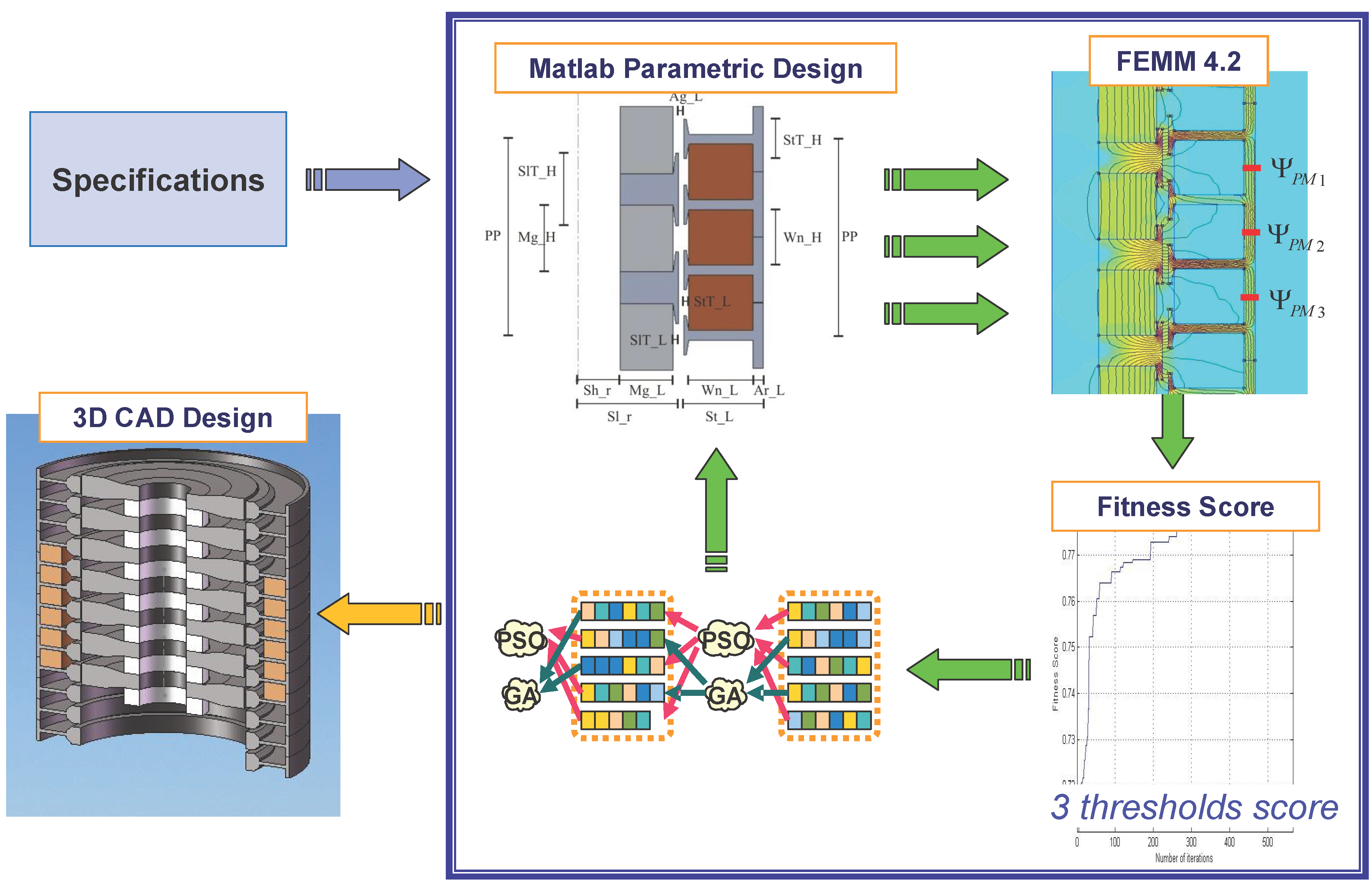
Referring to the
Figure 4, the automated design procedure proposed for TPM-LiG is organized in the following tasks:
Figure 4.
Flow chart of the design and optimization algorithm.
Figure 4.
Flow chart of the design and optimization algorithm.
Input: Analysis of specifications. In order to match the performances of the machine with the given specifications, it is necessary to set up the desired performances thresholds for the
fitness function (see
Section 3.2).
GSO initialization: the GSO algorithm produces a new pattern of geometric variables, i.e., a random configuration.
Generation of TPM-LiG geometry: the algorithm built in MATLAB environment defines a configuration of TPM-LiG by drawing the geometric shape of the system in the FEMM 4.2 workspace [
30].
FEM simulation: the algorithm executes FEMM 4.2 to calculate the distribution of the magnetic field in the system and it measures PM fluxes in the stator armour behind each winding of the three coils. It also calculates the cogging force acting on the slider.
Electromotive force (EMF) waveform: the algorithm moves the slider step by step and repeats the operations of the previous task reconstructing the cogging force and the EMF curves by interpolating all the measures. This analysis can be conducted with or without electrical load: by specifying the impedance of the load, the algorithm calculates the current inducted in the coils at the iteration and uses those values to define the currents in the coils at the iteration .
Fitness score evaluation: by using a multi-objective criterion, the fitness function assigns a score to the geometric configuration of TPM-LiG to evaluate the distance of the machine performances from the given specifications.
GSO evolution: the score obtained from the fitness function is used by GSO operators to produce a new pattern of geometric variables. The loop restarts from step 3.
Output: when the performances of TPM-LiG simulated by FEMM 4.2 are sufficiently close to the given specifications, this iterative procedure stops and a three-dimensional CAD data sheet relative to the optimized configuration is printed as output for manufacturing.
The above-described approach allows to design a new tubular generator in few hours simply by starting from the specifications, without any preliminary consideration about the topology of the machine, such as the presence of armour boots, the shape of spacers or the number of turns in windings.
The next section presents the numerical model of the system, with a description of the geometry of the device and details on its numerical modeling.
3. Linear Generator Optimization
The procedure described in the previous section is here applied to the design of a TPM-LIG for the power-bump application [
31].
3.1. System Description
As shown in
Figure 5, this machine is equipped with a modular stator winding in which the coils of each phase are disposed adjacent to each other. When the slider is moved, the fluxes originated by PMs link each phase according to phases’ mutual distances so that an appropriate space shifting allows the desired output voltage generation.
Figure 5.
Schematic of three-phase TPM-LiG with a modular stator winding.
Figure 5.
Schematic of three-phase TPM-LiG with a modular stator winding.
The parametric analysis presented [
32] shows that it is possible to modify the harmonics of the generated voltage in order to obtain either a quasi-square or a triangular waveform. Such versatility is due to the physical complexity of the system that depends on a large number of geometric and physical variables [
16]. This feature makes this technology suitable in energy harvesting applications.
To employ this technology to supply a small electronic device, it is desirable to design a TPM-LiG capable of producing a constant output voltage, since the available energy depends on the time-integral of power. Moreover, by using a three-phase generator equipped with a simple AC-DC converter such as an ideal three-phase Graetz bridge, authors aim to maximize the root mean square (RMS) of rectified voltage, reducing as much as possible the ripple and the cogging force effects.
Pursuing this objective, a simulation tool based on FEM engine of “Finite Element Method Magnetics Software” [
30] has been built in MATLAB environment as a numerical model connected to the GSO algorithm. By means of an iterative procedure, the simulation tool measures the cogging force and PMs’ fluxes in the stator armour behind each winding, as shown in
Figure 6, and it evaluates the electromotive force (EMF) assuming a continuous velocity as dynamic profile for the slider motion.
Figure 6.
Field distribution within the TPMLiG coils.
Figure 6.
Field distribution within the TPMLiG coils.
The stator is equipped with three winding slots. The slot fill factor is assumed to be closed to
, and the air gap in the winding slot is ignored in the simulation model. The slider consists of a hollow shaft and permanent magnets separated by iron spacers. A permanent magnet with grade
(
kA/m,
T) is used to provide a high-density magnetic field. Magnets are axially magnetized and mounted alternately on the shaft in order to maximize the magnetic poles utilization. The core and the spacers are considered to be realized by using pure iron with nonlinear
B–H curve. The three coils cover a whole pole pitch to increase the linked flux and obtain a trapezoidal waveform. All the variables considered in the parametric analysis are shown in
Figure 7, and the values selected by the optimization analysis are summarized in
Table 1.
Figure 7.
Schematic of TPM-LiG’s geometric variables considered in the parametric analysis.
Figure 7.
Schematic of TPM-LiG’s geometric variables considered in the parametric analysis.
Table 1.
Geometrical Parameters Range.
Table 1.
Geometrical Parameters Range.
| Variable | Name | Value [mm] |
|---|
| Axial Parameters |
| Pole pitch | | |
| Magnet height | | |
| Slider tooth height | | |
| Winding Height | | |
| Stator tooth height | | |
| Radial Parameters |
| Stator outer radius | | |
| Air gap | | 1 |
| Stator Thickness | | |
| Winding thickness | | |
| Stator armour thickness | | |
| Shaft outer radius | | |
| Magnet Thickness | | |
3.2. Numerical Model
In order to characterize the electromagnetic behavior of TPM-LiG, a parametric analysis has been developed along the radial direction and along the axial direction, considering the effects of all the different parameters involved in the geometrical configuration of the machine at the same time. Authors have also defined two per-unit systems identifying a base unit quantity for each direction to maintain a general approach. As shown also in
Table 1, this choice allows to provide an adimensional analysis, since all the variables of the same axis are expressed as a fraction of a common defined base.
The data interface between optimization algorithm and numerical model is managed by a built-in function called fitness function. It is worth noting that the fitness function is the only link between the numerical model of the physical problem and the optimization procedure. The fitness function decodes the information provided by GSO into geometrical dimensions assigned to TPM-LiG design; afterwards, the fitness function analyzes the new configuration, and then it evaluates the maximum peak value of cogging force () acting on the slider, the root mean square value () and the per unit ripple value () of output voltage expressed as functions of slider position. The fitness function also takes into account the maximum value of EMF generated by moving slider PMs and the RMS rectified output voltage of AC-DC ideal converter.
The selection of the parameters evaluated by the fitness function is crucial for the definition of the objective function. In fact, the aim of optimization algorithms is to find a solution that represents a global maximum or minimum in a suitably defined domain. In order to maximize the energy transferred by TPM-LiG from the power bump surface to the electronics, it is desirable to have the greatest value of generated voltage with the RMS value of rectified voltage close to one, which requires an EMF with a trapezoidal waveform. Moreover, it is necessary to reduce the cogging force as much as possible.
To reach out these different objectives, authors chose a constrained multi-objective approach [
33] by adopting thresholds for the fitness score value
f in order to identify three different phases into the fitness score evaluation. Fitness score value
f is then maximized by GSO algorithm according to the following expressions:
where
is the per-unit ripple value of output voltage and
is the desired level for
. Whenever the ripple value
stays above the threshold
, the objective of GSO is to minimize it, as expressed by Equation (
1).
When the value of
is maintained below
, the objective function becomes:
This condition allows to minimize the maximum peak value of cogging force
, until the second threshold
is reached, since
N represents the desired maximum level of
.
While the value of
is maintained below
, for maximizing the RMS of output voltage
the objective function
f becomes instead:
where
V represents the minimum desired level for the RMS output voltage
.
The objective function described above is defined to reach three successive objectives, producing a high, quasi-constant output voltage with the smallest cogging force. Any fitness score value means that all the requirements have been satisfied.
A prototype of tubular linear generator designed with the automated approach described here is presented in the next section.
4. Prototype Measurements
In previous sections, a novel modeling approach for tubular generator design has been proposed as optimal solution in terms of time—computing and projecting costs.
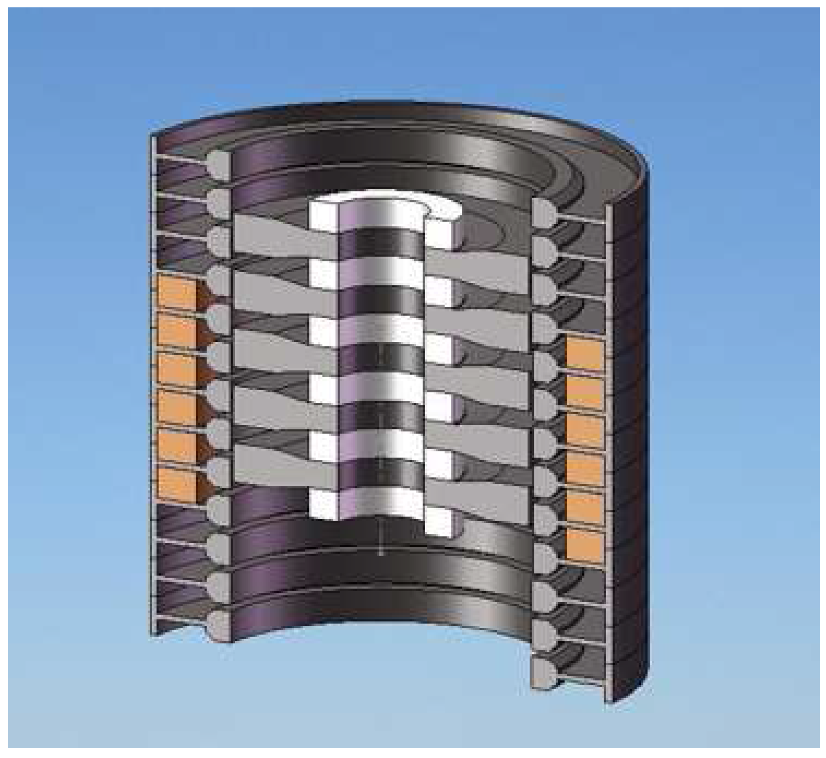
A prototype of TPM-LiG has been manufactured to verify the prediction model, design, analysis, and resulting performance. It is composed by 13 pure-iron stator and 7 pure-iron slider elements mounted on the shaft with 8 NdFeB N42 permanent magnets and 6 windings between the stator elements (as shown in
Figure 8).
Figure 8.
Section of the optimized TPM-LiG.
Figure 8.
Section of the optimized TPM-LiG.
In the prototype manufacturing process, the air gap forces appeared to be of highest importance, whereas the handling of permanent magnet proved to be much more difficult than expected. The smallest feasible air gap was mm for the prototype generator. Smaller air gap was hard to obtain because of the difficulties in the assembling phase.
In order to achieve the best measuring conditions, a tubular machine has been chosen as actuator for generator test bed.
4.1. Generator Test Bed
The generator test bed has been designed ad-hoc to fit the dimensions of tubular actuator.
The linear guide lies on a steel frame assembled to hold the stator of the actuator, so that the magnetic shaft of the linear motor is bounded by the frame itself.
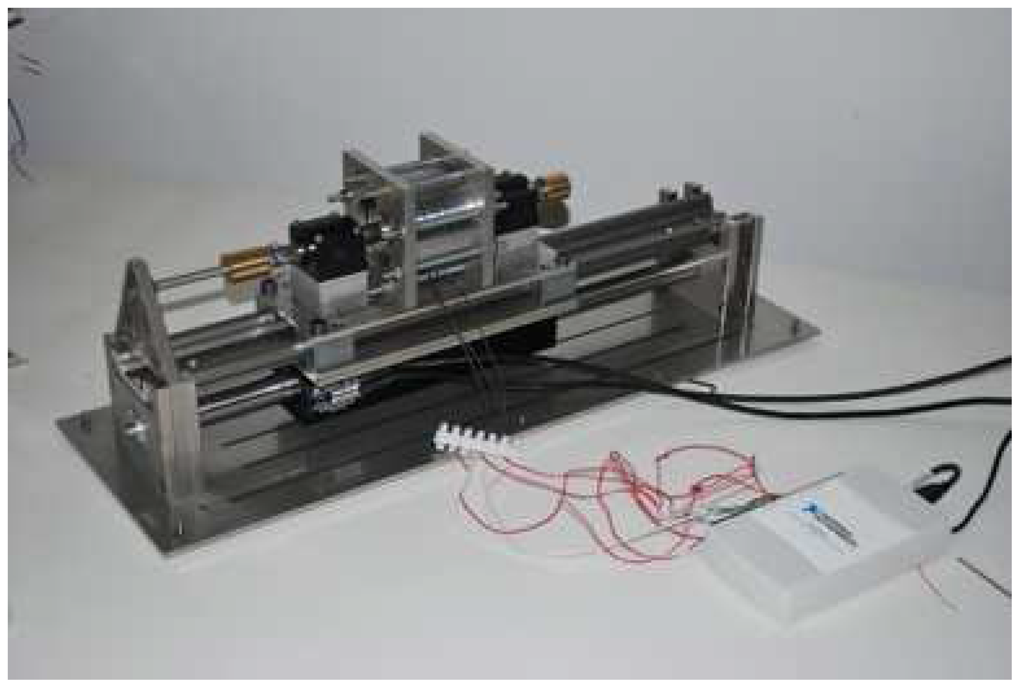
Figure 9 shows the assembled test bed with the TPM-LiG. Tests were made with sliding stator and fixed shaft. A simple screw is used to block the generator shaft into position.
Figure 9.
Experimental prototype test bed.
Figure 9.
Experimental prototype test bed.
A linear shaft drive is used for motion control: the
SHM/SHD (a new cylinder model linear motor system [
34]) equipped with a 25 mm magnetic shaft is designed to be driven without an external position sensor because the magnetic flux, generated by the shaft, enables position detection. Thrust force can occur immediately after starting because the position of magnetic pole can be detected by the built-in position sensor that enables operation without using external magnetic pole to detect elements. In addition, complex position driving is possible without an outer controller because the driver has built-in position driving function.
The inverter is an SHD 08 25 linear drive with kVA power supply equipment capacity. It is equipped with fast pulse input from outside as command input in pulse command mode, where the maximum pulse frequency is 4 Mpps.
4.2. Experimental Prototype of Tubular Generator
The objective of these measurements is to validate the design, analysis, and resulting performance. In particular, we wanted to prove the correspondence between measured and predicted EMF waveforms. Since the analysis of TPM-LiG presented in this work is based on the hypotheses that the velocity of slider is quasi-constant for all the dynamic across the pole pitch, the linear drive is set to move the stator of tubular generator with constant velocity mm/s.
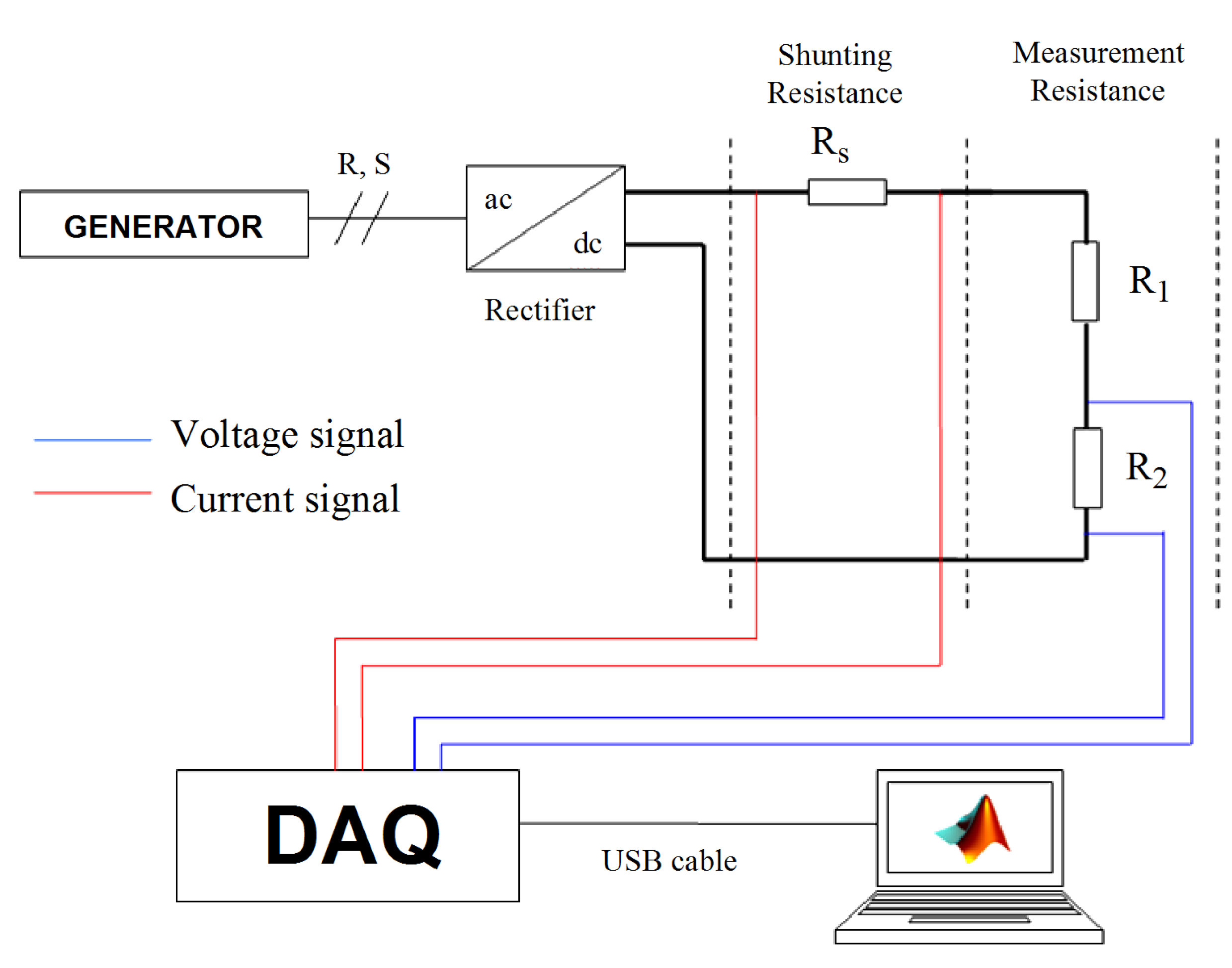
Measurements were made in a differential mode in order to filter the many interferences propagated by the inverter. A
NI USB–6216 National Instruments data acquisition board is used as shown in
Figure 10.
Figure 10.
A scheme of the implemented measuring circuit.
Figure 10.
A scheme of the implemented measuring circuit.
In
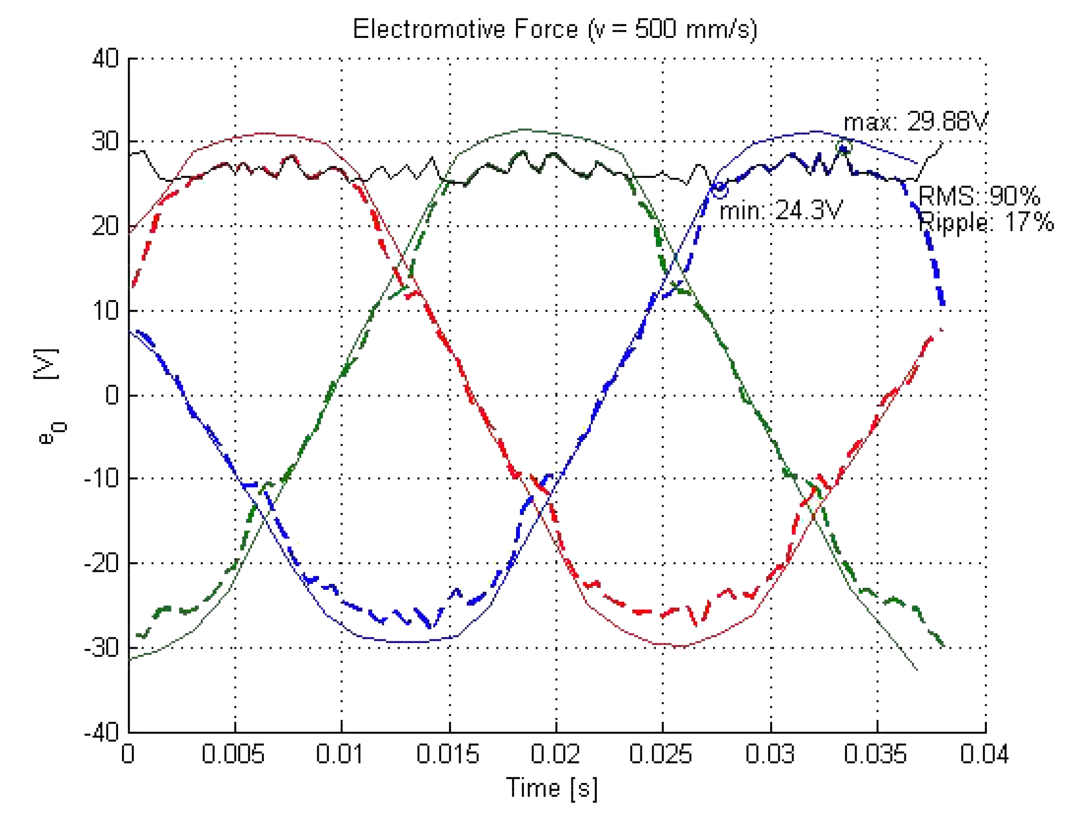
Figure 11 and
Table 2, the results of measurements are compared with the simulation expected values on the double three-phase.
The experimental results verify, to a large extent, the numerical tool used in the design process.
Figure 11 shows how it is effectively possible to achieve a trapezoidal shape of EMF in order to take advantage of a quasi-constant rectified voltage.
Figure 11.
Trend of the Electromotive Force in the three phases of TPM-LiG: the predicted (thin lines) compared with the measured (bold lines). The black line represents the trend of output voltage if a Graetz rectifier is used with a double three-phase generator.
Figure 11.
Trend of the Electromotive Force in the three phases of TPM-LiG: the predicted (thin lines) compared with the measured (bold lines). The black line represents the trend of output voltage if a Graetz rectifier is used with a double three-phase generator.
Table 2.
Prototype resulting performances.
Table 2.
Prototype resulting performances.
| Variable | Threshold | Simulation | Measure |
|---|
| ≥ 24 V | 28.07 V | 24.3 V |
| Ripple | ≤ 15% | 11.48% | 17.28% |
| ≤ 5 N | 2 N | 4 N |
Neglecting the losses due to the Graetz bridge, the expected RMS value of rectified voltage is equal to of maximum output voltage , with a ripple of that is under the objective. On the other hand, the measured RMS value is equal to of the maximum output voltage ( with respect of the predicted), with a ripple of ().
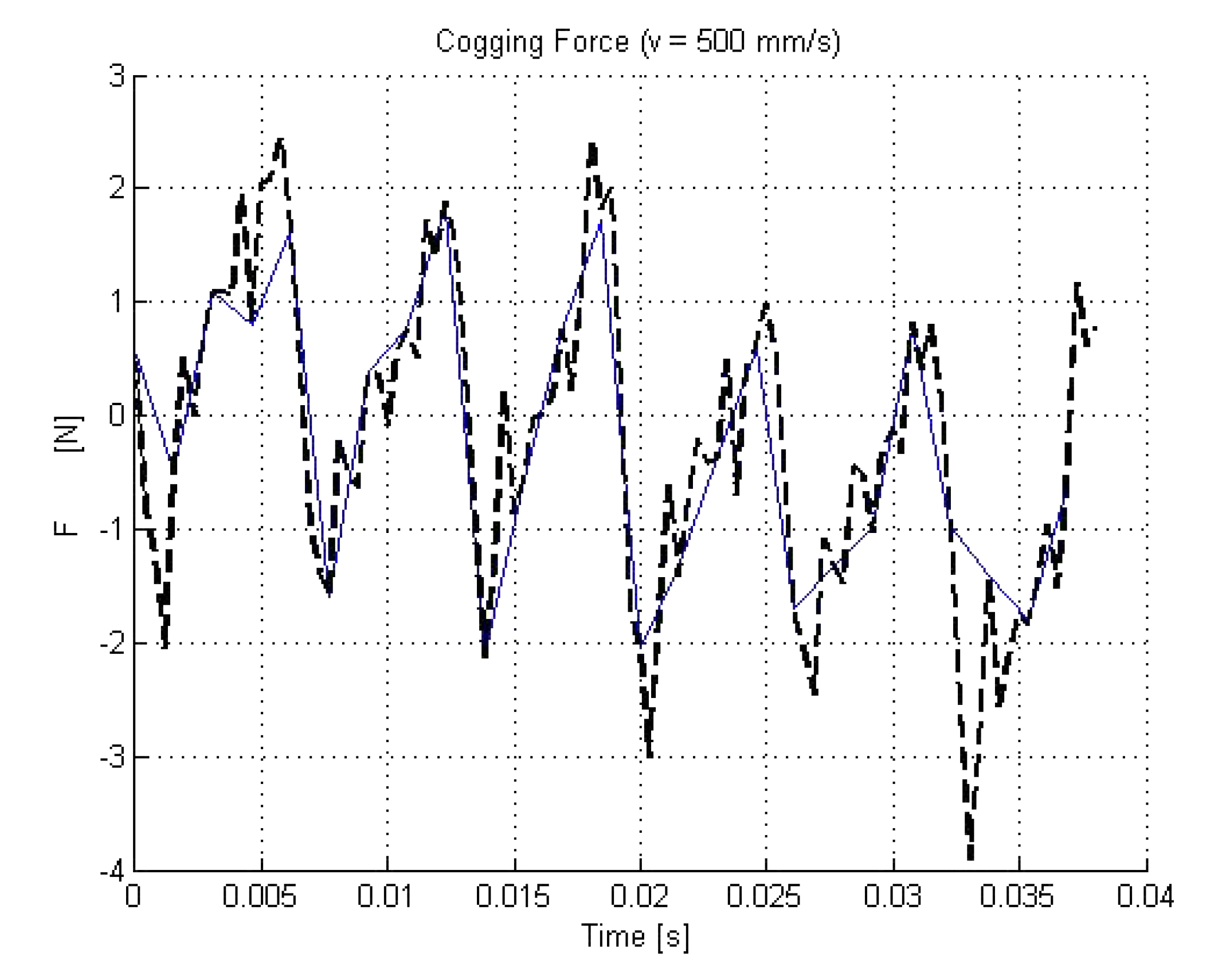
As shown in
Figure 12, according to the numerical model, the optimized cogging force effects are reduced to an amount included into the interval
N. This feature causes an oscillation of
on the average force of 200 N applied by the car wheel. However, on the test bed the cogging force effect occurs in the interval
N, still smaller than
N, causing an oscillation less than
compared with the average force applied by the car wheel.
Figure 12.
Trend of the Cogging Force: the predicted (thin line) compared with the measured (bold line).
Figure 12.
Trend of the Cogging Force: the predicted (thin line) compared with the measured (bold line).
The most significant result obtained with the proposed approach can be observed in the output voltage: the measured minimum value is V, which is very close to the desired 24 V and less than the V expected from simulation.
The small gap between expected and measured EMF trends has to be attributed to the absence of empirical coefficients in the predictive model. In fact, the developed simulation tool does not take into account the tolerance of manufacturing errors. This aspect will be integrated in a future version of modeling approach.
4.3. Perspective Impact on Traffic Energy Conversion
Preliminary bench test performed on a real speed bump (
Figure 13) revealed that a single power bump ten meters long installed in the proximity of a roundabout with an average of 10,000 crosses per day can recover up to 200 MWh per year. The same amount of energy is produced by a 170 kWp PV plant with a surface of 1200 square meters. A plant of this size can potentially supply sixty families or fully recharge ten electric vehicles per day, saving up to 250,000 kg of
per year.
Figure 13.
Experimental test on a power bump.
Figure 13.
Experimental test on a power bump.
5. Conclusions
In this paper, a novel hybrid optimization technique has been effectively used for the optimization of a tubular linear generator for energy harvesting from vehicles to grid.
The suitability of employing a tubular PM brushless machine equipped with modular stator elements for harvesting energy from traffic has been discussed. The performance of the tubular machine has been analyzed by FEM calculations, and it has been shown that the design of the machine can be optimized according to the given specifications.
Test in progress confirmed that the novel modeling approach can be applied to design TPM-LiG for small electronic devices and power grid connection as well. The proposed novel device is a promising technology for energy efficiency and environmental sustainability in the future, since it recovers energy from urban traffic typically in highways tolls, logistics centers, school pedestrian crossings and roundabouts towards the Smart City concept.


