Article

Proportional-Resonant Control of Doubly-Fed Induction Generator Wind Turbines for Low-Voltage Ride-Through Enhancement

1
School of Electrical Engineering and Automation, Tianjin University, Tianjin 300072, China
2
College of Physics & Electronic Engineering, Henan Normal University, Xinxiang 453007, China
3
School of Electrical Engineering & Automation, Tianjin Polytechnic University, Tianjin 300160, China
*
Author to whom correspondence should be addressed.
Energies 2012, 5(11), 4758-4778; https://doi.org/10.3390/en5114758
Submission received: 6 September 2012 / Revised: 5 November 2012 / Accepted: 5 November 2012 / Published: 19 November 2012

Abstract

:
A novel control strategy is proposed in this paper for the rotor side converter (RSC) of doubly-fed induction generator (DFIG)-based wind power generation systems. It is supposed to enhance the low-voltage ride-through (LVRT) capability of DFIGs during great-level grid voltage dips. The strategy consists of a proportional-resonant (PR) controller and auxiliary PR controllers. The auxiliary controllers compensate the output voltage of the RSC in case of grid faults, thus limiting the rotor inrush current of DFIG and meeting the requirements of LVRT. Sequential-component decompositions of current are not required in the control system to improve the response of system. Since the resonant compensator is a double-side integrator, the auxiliary controllers can be simplified through coordinate transformation. The feasibility of the control strategy is validated by simulation on a 1.5 MW wind-turbine driven DFIG system. The impact of the RSC converter voltage rating on the LVRT capability of DFIG is investigated. Meanwhile, the influence of angular frequency detection and control parameters are also discussed. Compared with traditional vector control schemes based on PI current controllers, the presented control strategy effectively suppress rotor current and reduce oscillations of DFIG power and torque under grid faults.

1. Introduction

The doubly-fed induction generator (DFIG) has been widely used in the variable-speed constant-frequency (VSCF) wind energy conversion systems as a result of its low converter capacity and independent control of active/reactive powers [1,2,3,4,5]. The stator of the DFIG is directly connected to the grid, while the rotor is linked to the grid by a back-to-back converter [6,7]. A rotor side converter (RSC) is applied to control generator speed and reactive power, and a grid side converter (GSC) is adopted to control dc-link voltage. With the stator directly connected to the grid, the DFIG is very sensitive to grid faults, especially to voltage dips [8]. An abrupt drop of grid voltage causes stator voltage sag and stator current oscillations, stator active/reactive power and electromagnetic torque. Furthermore, oscillation of the stator current leads to rotor current pulsation because of the strong coupling between them, thus affecting the performance of the DFIG. When the voltage dips reach a certain level, induction wind generators are usually disconnected to protect the rotor side converter [9,10,11]. Large scale disconnections will further weaken the grid and cause a considerable impact on the stable grid operation. Therefore, many countries are revising their grid codes in order to keep wind turbines connected to the grid and provide reactive power compensation to the grid in the case of voltage dips [12]. Considerable research has been done on dynamic behavior and ride-through capability of DFIG-based wind turbines under grid faults. A common solution is to supply a short circuit to the rotor windings with the crowbar, and then to disconnect the turbine from the grid to achieve the LVRT operation of wind turbines [13,14,15], which is easy to control and implement. For symmetrical voltage dips, the crowbar circuit only needs to be enabled at the moments of grid voltage fall and recovery to suppress rotor over-current. However, the crowbar circuit needs to be enabled throughout the whole dip due to a sustained rotor over-current caused by asymmetric voltage dips [16]. When the crowbar circuit is enabled, DFIG becomes a regular induction machine. In this case, instead of providing reactive power support to the grid, the generator absorbs large amounts of reactive power from the grid, which is not conducive to the grid recovery. To limit the rotor inrush current and enhance low voltage ride through the ability of the DFIG, appropriate control strategies for the rotor-side converter have been applied. Research on grid faults in the literature is usually classified into two categories. One is aiming at steady analysis of DFIGs during voltage unbalance [17,18,19,20]. In order to minimize the pulsation of torque and reactive power, measured torque and reactive power pulsation are used as the input of the controller to directly generate a rotor compensating voltage [17]. In [18] and [19], analysis and control of a DFIG-based wind generation system operating under unbalanced grid conditions are presented and a rotor current control strategy is used to control the rotor positive and negative sequence currents based on positive and negative reference frames. To eliminate the delay caused by positive and negative sequence decomposition of rotor current, dual current controllers are simplified by adding a resonant controller to the traditional PI controller [20]. On the other hand, various studies have been done on transient analysis in the case of voltage dips [21,22,23]. A new method is presented in [21], which is to generate the rotor current containing components opposite to the dc and negative sequence components in the stator flux linkage produced by grid voltage dips by controlling the rotor-side converter. To obtain the dc and negative sequence components of stator flux, a filter is usually applied. However, the response speed and stability of the control system are affected by the delay and errors caused by the filter [22]. Meanwhile, the active/reactive powers of the DFIG are no longer controlled in the case of grid faults. As referred in [23], the current coupling term affects the transient response of DFIGs under grid faults. Improved feed-forward transient compensations are added to the conventional current regulator so as to suppress the rotor fault current and enhance the LVRT capability. Negative sequence component and dc component also need to be extracted, thus leading to high computation loads and low response speeds.
To enhance the capability of LVRT for DFIGs under great-level voltage dips, a proportional-resonant (PR) current control strategy for RSC is proposed in this paper. The advantages of PR control are as follows: firstly, it requires no multiple frame transformations and be able to compensate the specified harmonic current [24,25,26,27,28]. Take [28] for instance, a sixth-order PR controller can be used to eliminate negative sequence fifth- and positive sequence seventh-order current harmonics induced by the lower-order voltage harmonics in the grid. Secondly, it has no coupling term affected by temperature and circuit parameters. Therefore, transient errors in the current coupling term reported in the literature [23] are avoided. In this paper, the control strategy for RSC consists of a main PR controller and auxiliary PR controllers. In the case of stator voltage dips caused by grid faults, the auxiliary controllers compensate the RSC output voltage to limit rotor fault currents without extracting dc and negative sequence components of the stator flux. Thus, it has rapid dynamic response.
This paper is organized as follows: Section 2 describes the behavior of a DFIG system under the conditions of symmetric and asymmetric grid fault. In Section 3, the DFIG control system is designed, and the structure of auxiliary controllers is simplified. Section 4 discusses the simulation results on a 1.5-MW DFIG system, analyzes the effect of the RSC voltage ratings on the LVRT capability of DFIG system and presents the influence of angular frequency detection and control parameters on LVRT feasibility of DFIG. Section 5 draws the conclusions.

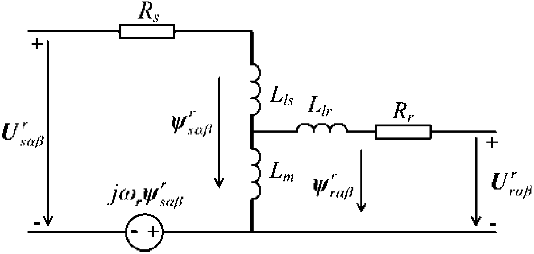
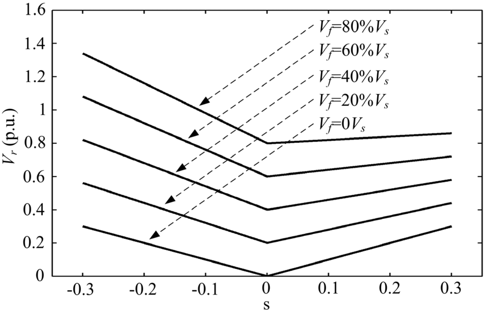
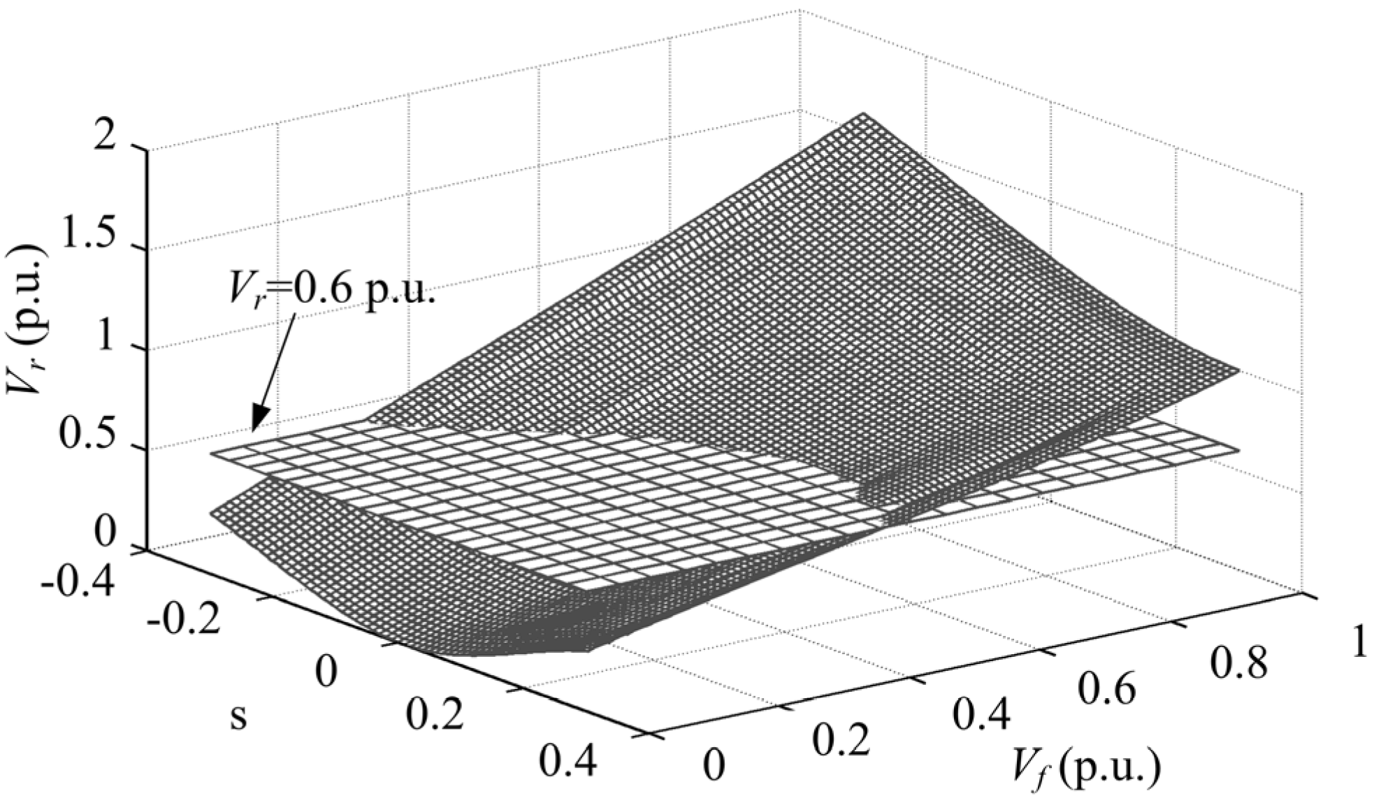
2. DFIG System Behavior during Grid Fault

As is shown in Figure 1, the generalized equivalent circuit of a DFIG is expressed in an arbitrary reference frame rotating at rotor angular speed of ωr. According to Figure 1, the voltages and flux linkage of stator and rotor are given respectively by:
{ U s α β r = R s I s α β r + d d t ψ s α β r + j ω r ψ s α β r U r α β r = R r I r α β r + d d t ψ r α β r
{ ψ s α β r = L s I s α β r + L m I r α β r ψ r α β r = L m I s α β r + L r I r α β r
where Rs and Rr are stator and rotor resistance, Ls = Lls + Lm and Lr = Llr + Lm are the self-inductances of stator and rotor winding, Lls , Llr and Lm are the stator and rotor leakage inductance and mutual inductance, respectively.
Figure 1. Equivalent circuit of a DFIG in an arbitrary reference frame rotating at a speed of ωr.
Energies 05 04758 g001
According to (2), rotor flux ψ r α β r and stator current I s α β r are expressed by:
ψ r α β r = L m ψ s α β r L s + σ L r I r α β r
I s α β r = ψ s α β r + L m I r α β r L s
where σ = 1 L m 2 / ( L s L r ) is the leakage factor.
Substituting (3) into (1), the rotor voltage is calculated as:
U r α β r = R r I r α β r + σ L r d I r α β r d t + L m L s ( U s α β r R s I s α β r j ω r ψ s α β r )
The spatial relationship between the stator flux in the stationary reference frame (αβ) and that in the rotor reference frame (αrβr) is shown in Figure 2. Suppose that ωs is the grid angular frequency, a static dc component and a negative sequence component with the angular frequency of −ωs appear in the stator flux linkage under grid fault conditions [21].
Figure 2. Spatial relationships between the stationary αβ reference frame and the rotor αrβr reference frame.
Energies 05 04758 g002
From Figure 2, the stator flux linkage in the stationary reference frame (αβ) is written as:
ψ s α β ( t ) = ψ s α β + ( t ) + ψ s α β D C ( t ) + ψ s α β ( t ) = | ψ s α β + | e j ( ω s t + φ + ) + | ψ s α β D C | e t / τ s + | ψ s α β | e j ( ω s t + φ )
where τs = Ls/Rs is attenuation time constant of dc component, φ+ and φ are initial phase of positive and negative sequence component of stator flux linkage.
Positive sequence component, dc component and negative sequence component of the stator flux linkage in the stationary reference frame (αβ) are transformed into the rotor reference frame (αrβr) according to Figure 2:
{ ψ s α β + r = ψ s α β + e j ( ω s ω r ) t ψ s α β D C r = ψ s α β D C e j ω r t t / τ s ψ s α β r = ψ s α β e j ( ω s + ω r ) t
It is seen from Equation (6) that the fundamental current component with the angular frequency of ωsωr and the disturbing current components with the angular frequencies of ωr and ωs + ωr will be induced by the stator flux linkage in the rotor winding.
Figure 3 depicts the stator voltage and rotor current in the three-phase stationary coordinate frame, rotor current in the rotor reference frame and its DFT analysis during stator voltage dips of 50% caused by a three-phase-to-ground grid fault. It is assumed that the grid frequency is 60 Hz and the DFIG initially operates with full load at 25% super synchronous speed. Stator voltage dips due to a three-phase grid fault as depicted in Figure 3(a). Figure 3(b) shows that a high fault current is induced in the rotor windings. Figure 3(c) gives the rotor current in the rotor reference frame. As is seen, besides the fundamental component, a harmonic component is also included in the rotor current. From the DFT analysis in Figure 3(d), it can be seen evidently that apart from the fundamental component with slip frequency of ωsωr (15 Hz), a current component with the angular frequency of ωr (75 Hz) also appears in the rotor winding under the influence of the dc component in the stator flux linkage when the symmetrical voltage dips. The reason for this is that when the dc component of the stator flux rotates with the angular frequency of ωr with respect to the rotor, a current component with the angular frequency of ωr is induced in the rotor winding, which is a fault current of the rotor.
Figure 3. Rotor current and DFT analysis during a three-phase voltage dip. (a) Stator voltage; (b) Rotor current; (c) Rotor current in αrβr reference frame; (d) DFT analysis of rotor current.
Energies 05 04758 g003
The rotor current under symmetrical voltage dip conditions is given by:
I r α β r = I r α β 0 r + I r α β 1 r
Substituting (7) into (4), the rotor voltage under symmetrical voltage dips is calculated as:
U r α β r = R r I r α β r + σ L r ( d I r α β 0 r d t + d I r α β 1 r d t ) + L m L s ( U s α β r R s I s α β r j ω r ψ s α β r )
Figure 4 shows the stator voltage and rotor current in the three-phase stationary frame, rotor current in the rotor reference frame and its DFT analysis during stator voltage dips of 50% caused by a two-phase-to-ground fault. In the case of two-phase-to-ground dips of the stator voltage shown in Figure 4(a), it can be seen from the DFT analysis in Figure 4(d) that the rotor current in Figure 4(c) consists of current components with angular frequencies of ωr (75 Hz) and ωs + ωr (135 Hz) and a fundamental component in the rotor winding disturbed by the stator flux linkage. The reason is that when the dc and negative sequence components of stator flux rotate with the angular frequency of ωr and ωs + ωr with respect to the rotor, respectively, current components with the angular frequencies of ωr and ωs + ωr are induced in the rotor winding, which are also rotor fault currents.
The rotor current under asymmetrical voltage dips are given by:
I r α β r = I r α β 0 r + I r α β 1 r + I r α β 2 r
Substituting (9) into (4), the rotor voltage under asymmetrical voltage dips is calculated as:
U r α β r = R r I r α β r + σ L r ( d I r α β 0 r d t + d I r α β 1 r d t + d I r α β 2 r d t ) + L m L s ( U s α β r R s I s α β r j ω r ψ s α β r )
Figure 4. Rotor current and DFT analysis during a two-phase-to-ground voltage dip. (a) Stator voltage; (b) Rotor current; (c) Rotor current in αrβr reference frame; (d) DFT analysis of rotor current.
Energies 05 04758 g004

3. System Control

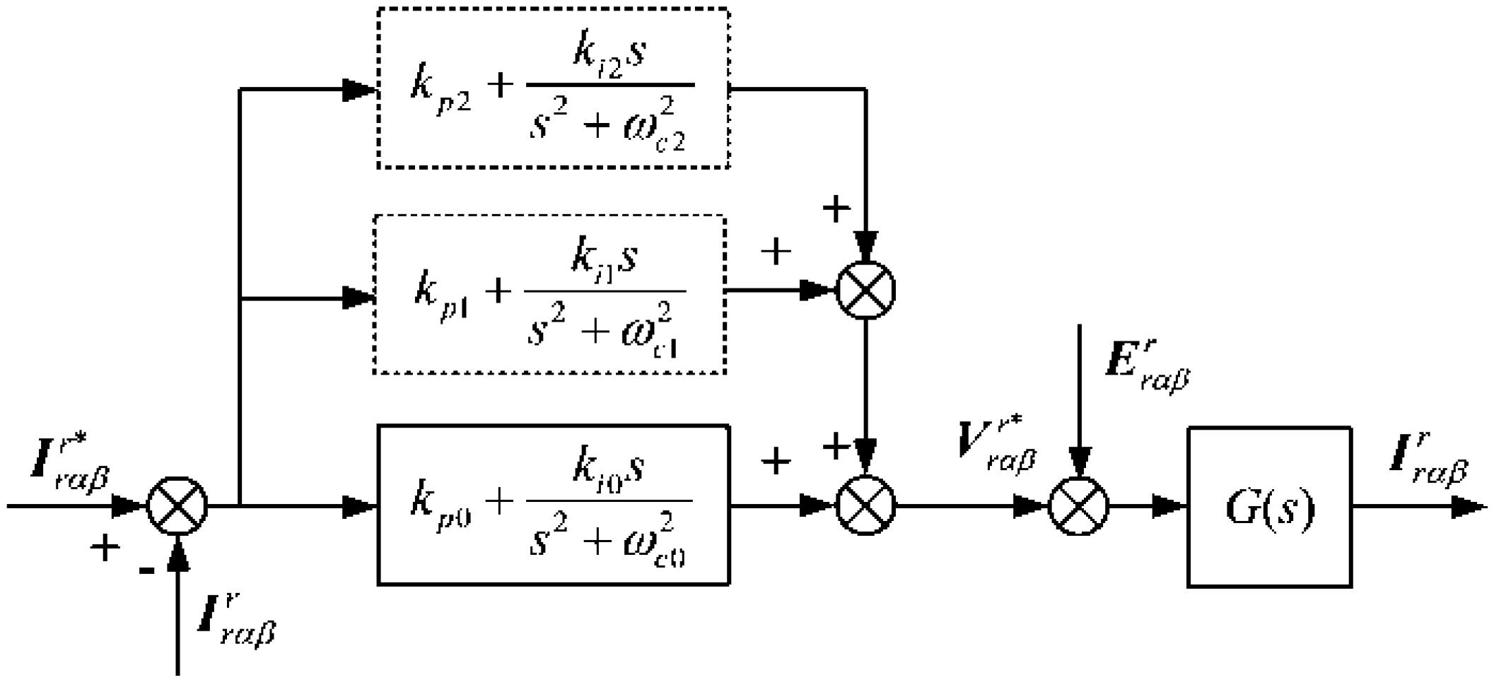
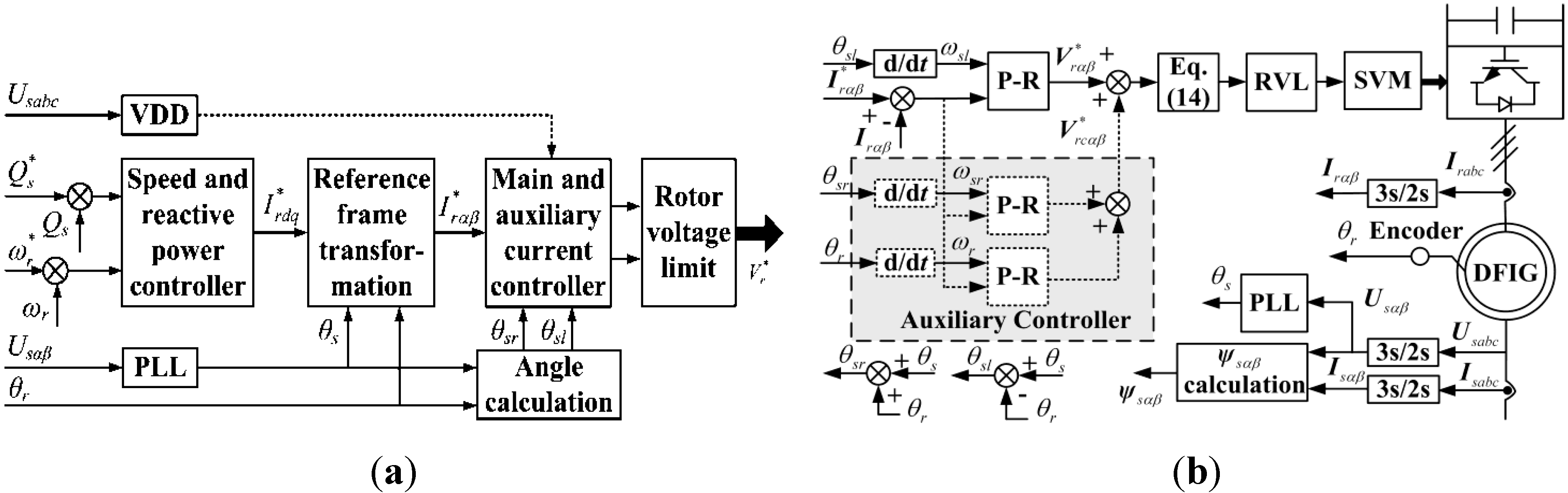
3.1. Proposed Control System Design

This paper presents a control scheme for the rotor side converter of a DFIG based on a PR controller. It consists of one main PR controller and two auxiliary PR controllers. The resonant frequency of the main PR controller is ωsωr and is used to control the active/reactive powers of the DFIG. In the case of a grid fault, the auxiliary PR controllers are applied to suppress the dc and negative sequence components of the rotor current, with the resonant frequencies of ωr and ωs + ωr, separately. The control scheme is implemented in the rotor reference frame without dc and negative sequence component decomposition of current. The transfer function of the main PR controller is:
H m ( s ) = k p 0 + k i 0 s s 2 + ( ω s ω r ) 2
where kp0 and ki0 are proportion and resonant constant of main PR current controller.
The transfer functions of the two auxiliary PR controllers are:
{ H a 1 ( s ) = k p 1 + k i 1 s s 2 + ω r 2 H a 2 ( s ) = k p 2 + k i 2 s s 2 + ( ω s + ω r ) 2
where kp1, kp2, ki1, ki2 are proportion and resonant constants of the auxiliary controllers.
The following equation is obtained from Equation (10):
σ L r ( d I r α β r d t ) = σ L r ( d I r α β 0 r d t + d I r α β 1 r d t + d I r α β 2 r d t ) = U r α β r * R r I r α β r L m / L s ( U s α β r R s I s α β r j ω r ψ s α β r )
where U r α β r * referred to the rotor control voltage produced by the PR controller, which is designed as follows:
U r α β r * = σ L r V r α β r * + E r α β r
where:
V r α β r * = d I r α β r d t = d I r α β 0 r d t + d I r α β 1 r d t + d I r α β 2 r d t = C P R ( s ) ( I r α β r * I r α β r ) = [ H m + H a 1 + H a 2 ] ( I r α β r * I r α β r )
E r α β r = σ L r V r α β r * + R r I r α β r + L m L s ( U s α β r R s I s α β r j ω r ψ s α β r )
I r α β r * is reference value of rotor current, and I r α β r is actual value of rotor current.
The following equation in component form is obtained from Equations (14), (15) and (16):
{ u r α r * = σ L r u r α + R r i r α r + L m L s ( u s α r R s i s α r + ω r ψ s β r ) u r β r * = σ L r u r β + R r i r β r + L m L s ( u s β r R s i s β r + ω r ψ s α r )
{ u r α = [ H m + H a 1 + H a 2 ] ( i r α r * i r α r ) u r β = [ H m + H a 1 + H a 2 ] ( i r β r * i r β r )
where u r α r * and u r β r * are reference value of rotor voltage, i r α r * and i r β r * are reference value of rotor current.
Figure 5 shows the rotor current control diagram based on the developed PR controller.
Figure 5. Rotor current control scheme based on PR controller.
Energies 05 04758 g005
Suppose:
{ a 1 = ( s 2 + ω c 0 2 ) ( s 2 + ω c 1 2 ) ( s 2 + ω c 2 2 ) a 2 = ( s 2 + ω c 1 2 ) ( s 2 + ω c 2 2 ) a 3 = ( s 2 + ω c 0 2 ) ( s 2 + ω c 2 2 ) a 4 = ( s 2 + ω c 0 2 ) ( s 2 + ω c 1 2 )
where ωc0 = ωsωr, ωc1 = ωr, and ωc2 = ωs + ωr.
The closed-loop transfer function of rotor current controller is:
F i ( s ) = I r α β r ( s ) I r α β r * ( s ) = C ( s ) G ( s ) 1 + C ( s ) G ( s ) = a 1 ( k p 0 + k p 1 + k p 2 ) + a 2 k i 0 s + a 3 k i 1 s + a 4 k i 2 s ( s 2 + ω c 0 2 ) ( s 2 + ω c 1 2 ) ( s 2 + ω c 2 2 ) G ( s ) + M ( s )
where:
M ( s ) = a 1 ( k p 0 + k p 1 + k p 2 ) + a 2 k i 0 s + a 3 k i 1 s + a 4 k i 2 s
Substituting s = j(ωsωr), s = −r and s = −j(ωs + ωr) into Equation (20) yields:
F i ( s ) = I r α β r ( s ) I r α β r * ( s ) = M ( s ) M ( s ) = 1
It can be implied from Equation (22) that the proposed PR current control scheme can provide zero steady-state error for ac signal with the frequencies of ωsωr, ωr and ωs + ωr regardless of the parameters Lr, σ, and Rr of DFIG.
From Figure 5, the transfer function between disturbance voltage and given current is calculated as:
F u ( s ) = I r α β r ( s ) E r α β r ( s ) = G ( s ) 1 C ( s ) G ( s ) = ( s 2 + ω c 0 2 ) ( s 2 + ω c 1 2 ) ( s 2 + ω c 2 2 ) ( s 2 + ω c 0 2 ) ( s 2 + ω c 1 2 ) ( s 2 + ω c 2 2 ) G ( s ) + M ( s )
Substituting s = j(ωsωr), s = −r and s = −j(ωs + ωr) into (23) results in:
F u ( s ) = I r α β r ( s ) E r α β r ( s ) = 0 0 G ( s ) + M ( s ) = 0
It is indicated from Equation (24) that the proposed PR control scheme eliminates the corresponding disturbance of respective frequency, regardless of the parameters Lr, σ, and Rr of DFIG.
The PR controller given above can be replaced by a non-ideal PR controller to solve the instability associated with infinite gain at the center frequency of the resonant term. Consequently, the non-ideal PR controller in the control system is given as follows:
G P R ( s ) = k p + k i ω i s s 2 + 2 ω i s + ω c 2
The bandwidth of the controller is regulated by ωi in Equation (25), which is helpful in reducing sensitivity to slight frequency variation in a typical grid. It is assumed that the synchronous rotation angular speed ωs = 120π rad/s and rotor speed ωr = 100π rad/s, then the resonant angular speed of the main controller is calculated as:
ω c 0 = ω s ω r = 20 π r a d / s
The resonant angular speeds of the two auxiliary controllers are expressed as:
{ ω c 1 = ω r = 100 π r a d / s ω c 2 = ω s + ω r = 220 π r a d / s
The frequency response of resonant controller under different ωi is depicted in Figure 6. It can be obtained from Figure 6 that the resonant peaks occur only at the selected frequencies of 10, 50, and 110 Hz which are the resonant frequencies of the controller. The controller becomes more selective with a smaller ωi. However, a smaller ωi will cause the controller to be more sensitive to frequency variations, which is unfavorable to system stability.
Figure 6. Open loop Bode plot of resonant controller.
Energies 05 04758 g006
According to Equation (14), a schematic diagram of the PR current control scheme for the rotor side converter of a DFIG is illustrated in Figure 7. Figure 7(a) shows the control structure of the overall system, and Figure 8(b) depicts the proposed current controller. As shown in Figure 7(a), a voltage dips detector (VDD) detects the grid voltage and determines whether or not to switch on the auxiliary controllers. The control system operates in the traditional mode with the auxiliary controllers disabled under normal conditions. When grid voltage dips are detected, the auxiliary controllers will be immediately enabled, generating the corresponding compensation of rotor voltage. As shown in Figure 7(b), the deviation of current is passed to the main controller and auxiliary controllers to generate the required rotor control voltage. The output voltage of the main controller and auxiliary controllers may exceed the capability of the RSC due to the limited voltage rating of the RSC. In order to ensure the normal operation of the DFIG, a rotor voltage limit (RVL) is applied to limit the output of the controller. Space vector modulation is then used to generate the required switching voltage vectors for the RSC to control the DFIG.
Figure 7. Schematic diagram of the proposed control system. (a) System control structure; (b) Proposed PR current controller.
Energies 05 04758 g007
At the instant of voltage dips, the output voltage of controller is required to be regulated quickly to suppress the current. The proposed control system will be implemented without the need to decompose the sequential components to improve the response of system. As shown in Figure 8(a), when there is a sudden voltage drop at 0.004 s, the proposed current controller generates the rotor control voltage rapidly and the dynamic process is very short with the maximum rotor voltage being less than 300 V. In [21], the DC component of flux during voltage drop is extracted by a band-pass filter, the current reference value is computed, and then the rotor voltage reference value is generated by the PI controller. The controller output voltage during voltage drop is shown in Figure 8(b). As can be seen from the figure, the delay of the filter affects the controller response. Compared to Figure 8 (a), a greater rotor voltage is required.
Figure 8. Controller output voltage during voltage drop. (a) Proposed PR current controller; (b) Current controller in [21].
Energies 05 04758 g008

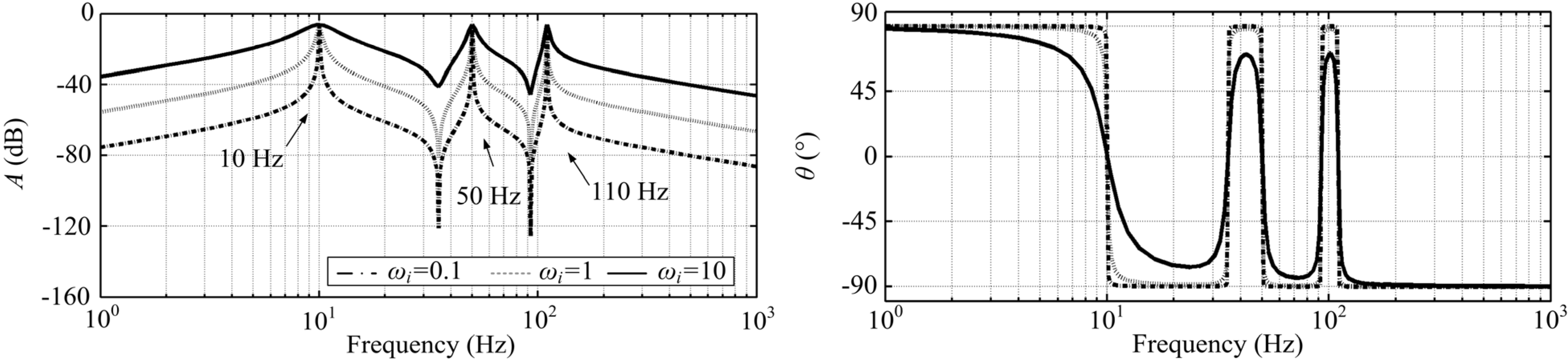
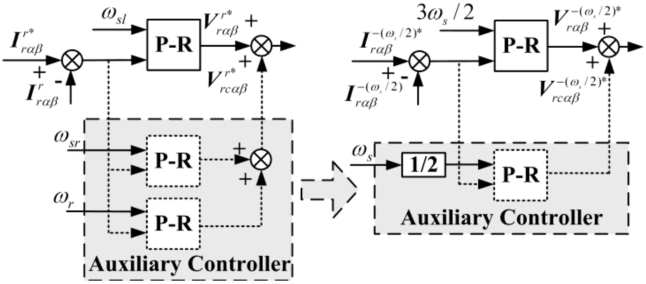
3.2. Simplification of the Auxiliary Controller

The components of the stator flux linkage generated in a grid fault are converted from the static coordinate frame to a negative reference frame rotating at the speed of −ωs/2:
{ ψ s α β + 1 2 ω s = ψ s α β + e j ( 3 2 ω s ) t ψ s α β D C 1 2 ω s = ψ s α β D C e j ( 1 2 ω s ) t t / τ s ψ s α β 1 2 ω s = ψ s α β e j ( 1 2 ω s ) t
It can be derived from Equation (28) that the components of the stator flux linkage are components with the angular frequencies of 3ωs/2 and ±ωs/2. According to Section 2, under grid fault conditions, the rotor current in the negative reference frame rotating at the speed of −ωs/2 contains ac components with the angular frequencies of both ±ωs/2 and 3ωs/2. Since the resonant controller is a doubly-side integrator, the resonant part tuned at the angular frequency of ωs/2 eliminates the error for both the positive sequence at the frequency of ωs/2 and the negative sequence at −ωs/2. Therefore, adoption of the PR controller tuned at ωs/2 eliminates the errors of the ac signal with the frequencies of ±ωs/2.
The auxiliary controllers are simplified as shown in Figure 9. The dc and negative sequence components of current are adjusted only by one PR controller implemented in the reference frame rotating at the speed of −ωs/2 and the control system is simplified. In addition transforming dc and negative sequence components into ones with the same frequency will effectively eliminate the impact between the various frequency components. It can also regulate the current according to both dc and negative sequence components.
Figure 9. Simplification of the PR controller.
Energies 05 04758 g009

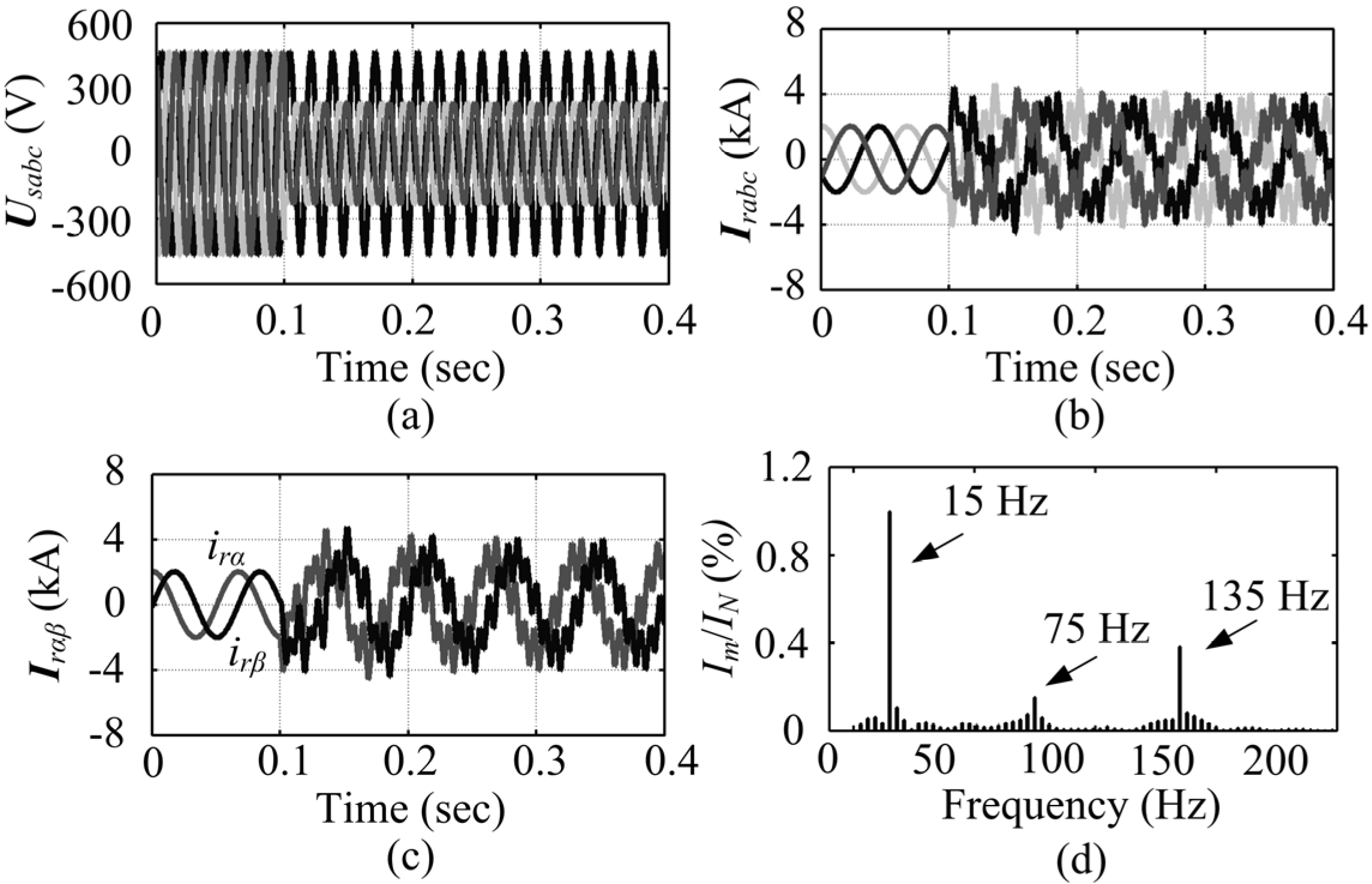
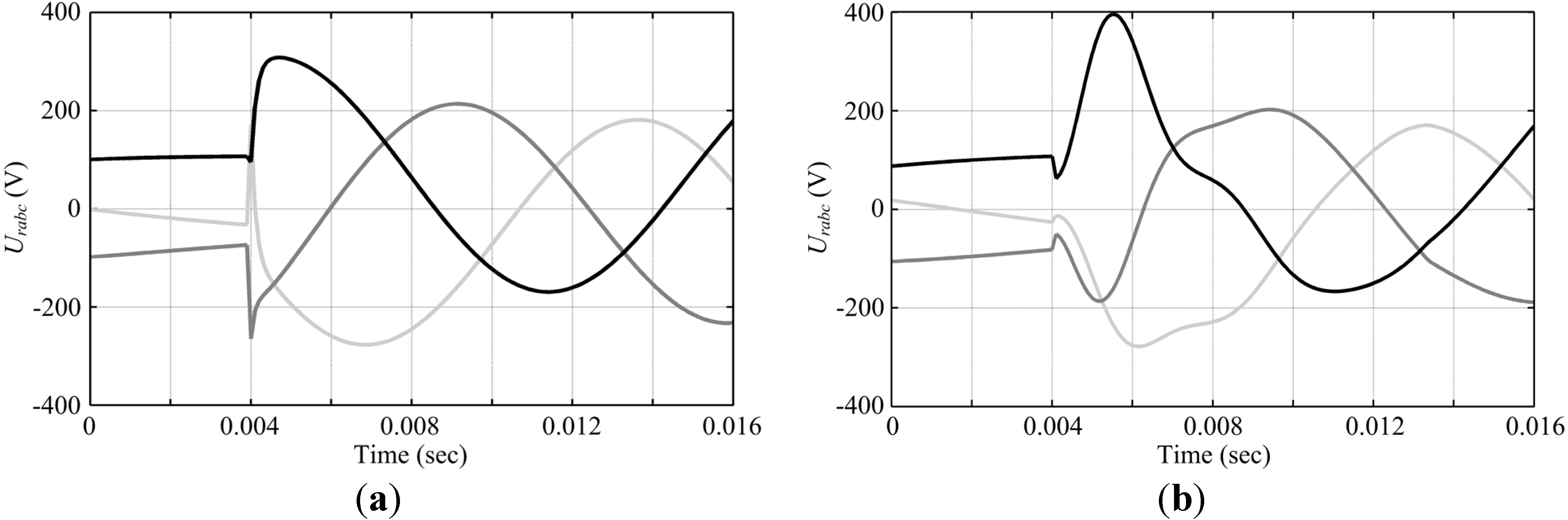
4. Simulation Results

To verify the theory and the proposed PR control strategy, simulation results based on MATLAB/Simulink are provided for a 1.5 MW DFIG-based wind generation system under stator voltage dips caused by grid fault. The system parameters are given in Table 1 [29].
Table 1. DFIG system Parameters.
DFIG ParametersValue
Rated generator power1.5 MW
Rated generator voltage0.575 kV
Frequency60 Hz
Stator resistance0.0014 Ω
Stator leakage inductance8.998 × 10−5 H
Rotor resistance9.9187 × 10−4 Ω
Rotor leakage inductance8.2088 × 10−5 H
Magnetizing inductance1.526 × 10−3 H
Pole pairs3
The DFIG-based wind generator is controlled by a RSC in the traditional system, and the main objective of the grid-side converter is to control the dc-link voltage by the pulse width modulation method. The dc link voltage is assumed to be 500 V, then the RSC maximum output phase voltage is about 290 V in peak value, and the phase current of rotor is 1.53 kA in RMS and 2.16 kA at peak value. From the analysis in Section 3, it is more difficult for the DFIG to ride through the faults under super-synchronous conditions. Thus, the rotor speed is assumed to be 1500 r/min with the slip s = −0.25 in the simulation.

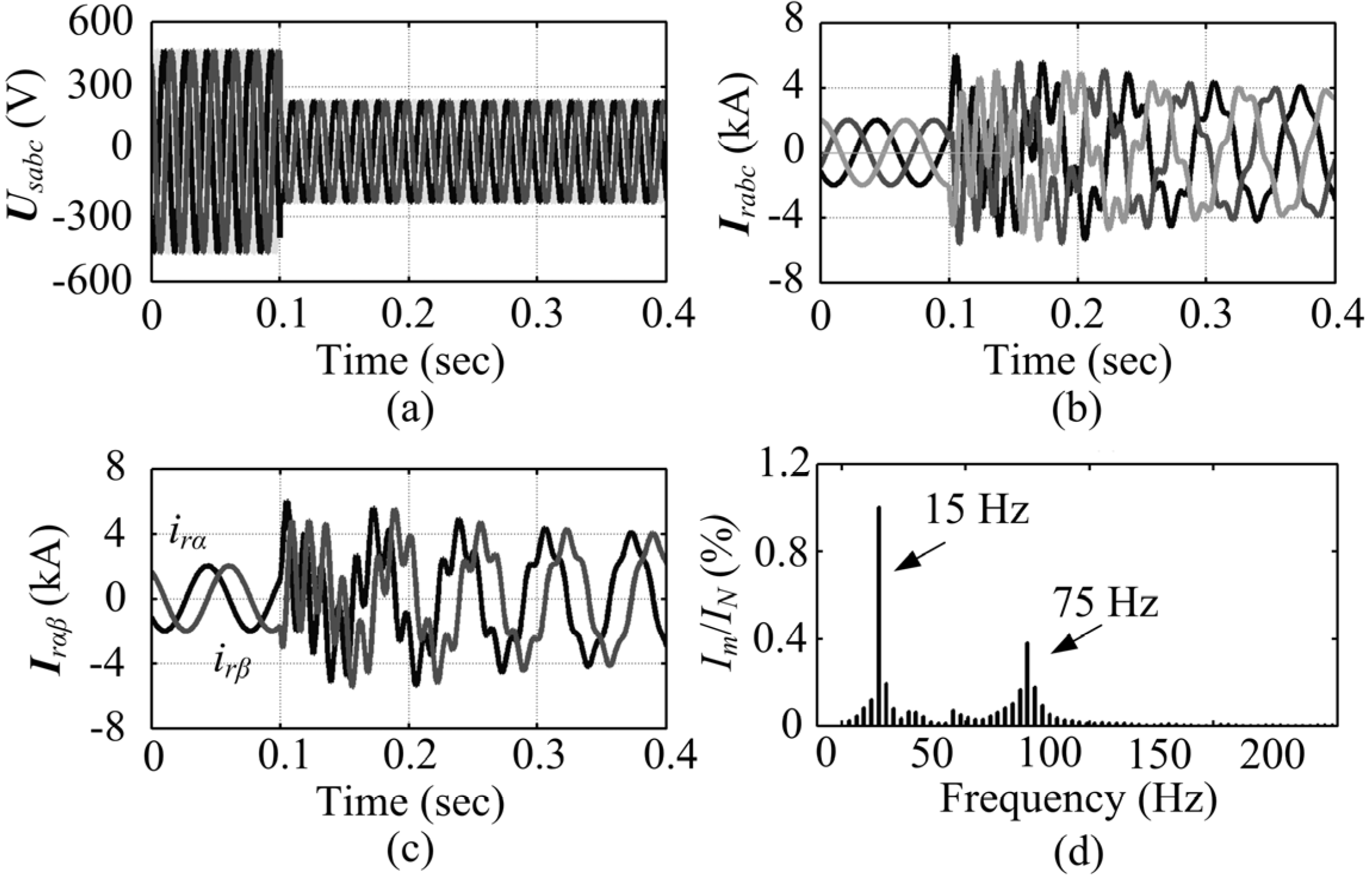
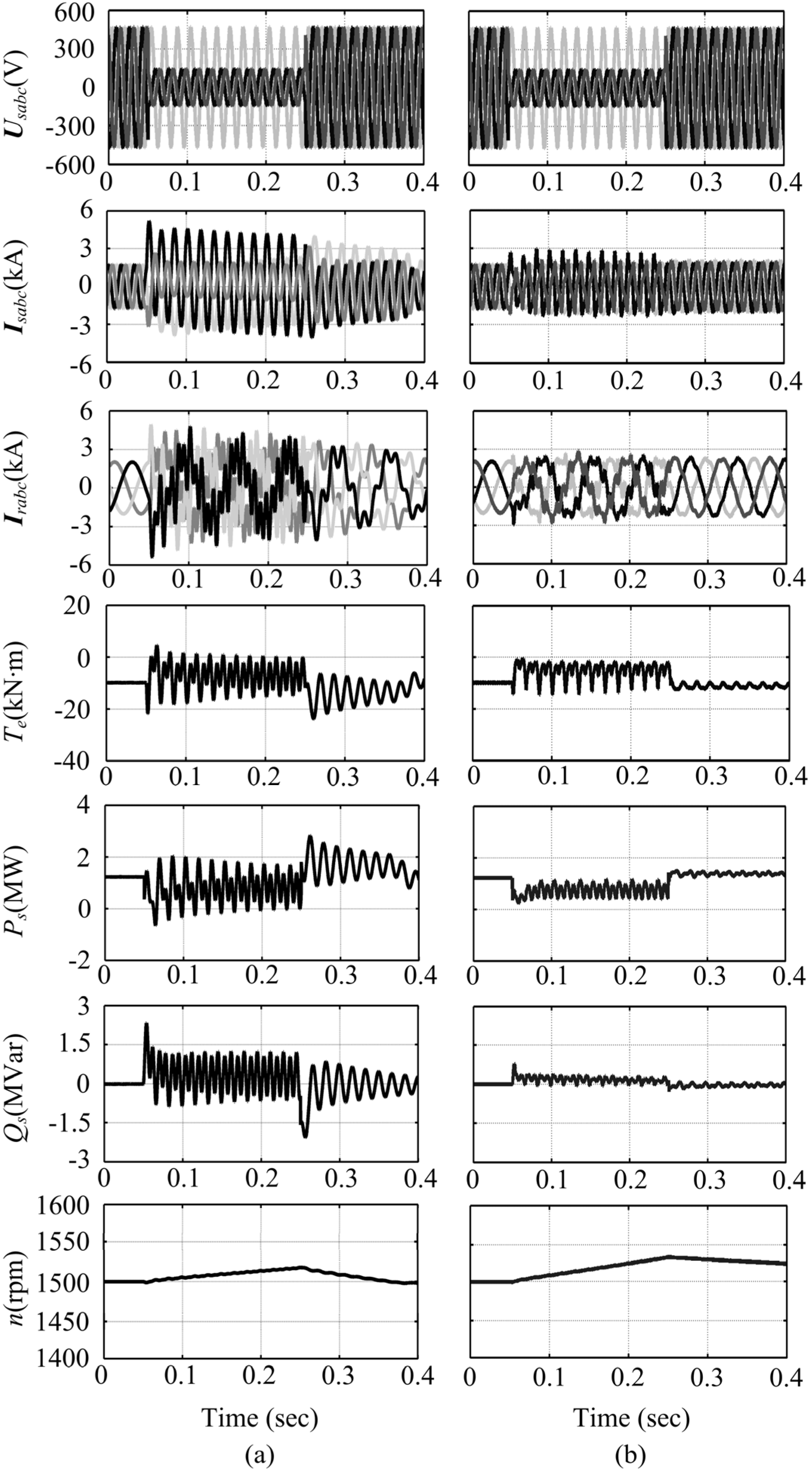
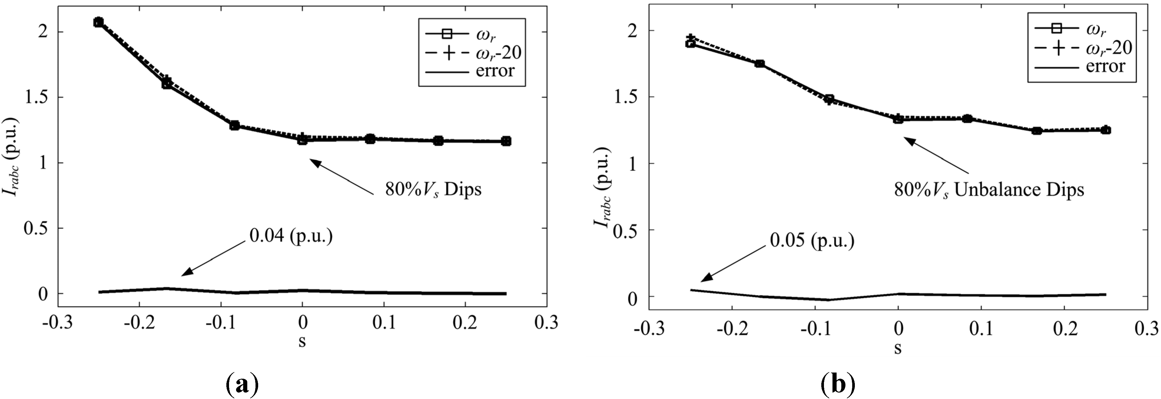
4.1. Three-Phase Fault

Figure 10(a) and Figure 10(b) compare the simulation results, with the conventional and the proposed control strategies adopted, respectively, when the stator voltage drops to 0.2 pu due to a three-phase fault. The fault occurs at t = 0.05 s and is cleared at t = 0.25 s.
Figure 10. Simulation results on a DFIG when an 80% balance voltage drop occurs. (a) Conventional control; (b) Proposed control.
Energies 05 04758 g010
Due to the dc component of the stator flux linkage caused by the stator voltage dips, stator and rotor currents increase dramatically and the rotor current shoots up to 8 kA at the beginning of the voltage dips and the rotor current shoots up and exceeds 8 kA at the moment of grid recovery by the conventional control method. In this process, the rotor current will exceed the maximum value of converter rating and the wind turbine needs to be disconnected from the grid, which is not good for both the normal operation of generator and the grid fault recovery. Stator active/reactive powers and electromagnetic torque result in a great pulsation, hence affecting the stability of the grid and increasing the mechanical stress on the turbine system. Compared with the conventional control strategy, the proposed method is able to suppress the rotor overshoot current to only 4 kA. It is worth noting that there exists some safety margin in power electronic design, so the DFIG can ride through faults using the proposed control scheme. Meanwhile, the pulsations of stator current, stator active/reactive powers and electromagnetic torque all decrease dramatically, resulting in improved dynamic behaviour of the DFIG under grid fault conditions.
Figure 11. Simulation results on a DFIG when a 50% balance voltage drop occurs. (a) Conventional control; (b) Proposed control.
Energies 05 04758 g011
Caused by a three-phase-to-ground fault, the stator voltage drops to 0.5 pu which is simulated with the output reactive power of generator equal to 0.5 MVar. The grid voltage dips at 0.1 s and recovers at 0.5 s in Figure 11. Compared with Figure 10(a), it is shown in Figure 11(a) that the over-current decreases with the adopted traditional control strategy when a fault occurs due to much lower voltage dips. However, a protection system like the crowbar has to be enabled as a result of the over-current. The proposed method is more effective than the traditional method in eliminating rotor fault currents and reducing oscillations of the stator active/reactive power and electromagnetic torque. Also the DFIG provides uninterrupted active/reactive power output to support the grid recovery.
Figure 12. Simulation results on a DFIG when a 70% phase-phase-ground voltage drop occurs. (a) Conventional control; (b) Proposed control.
Energies 05 04758 g012

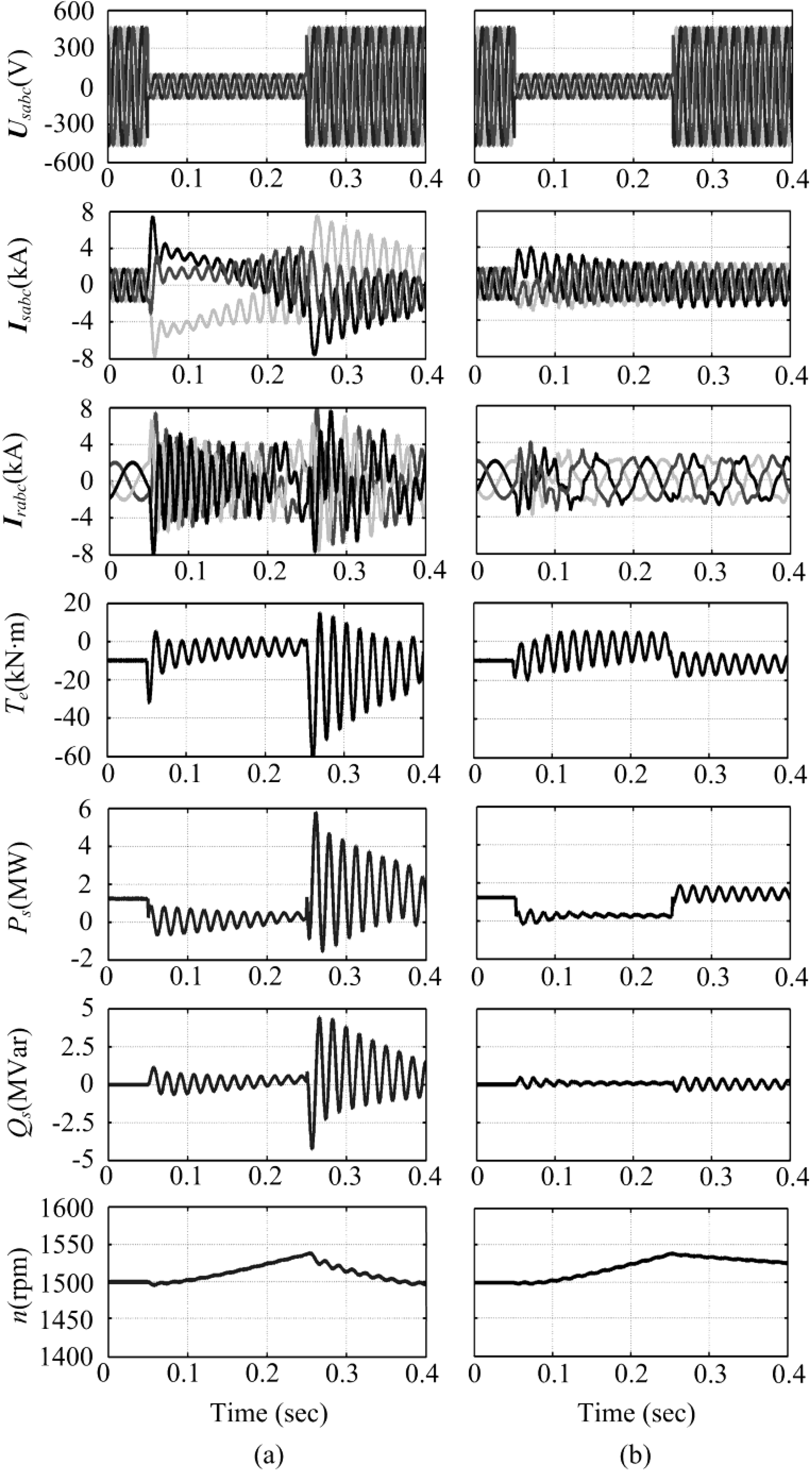
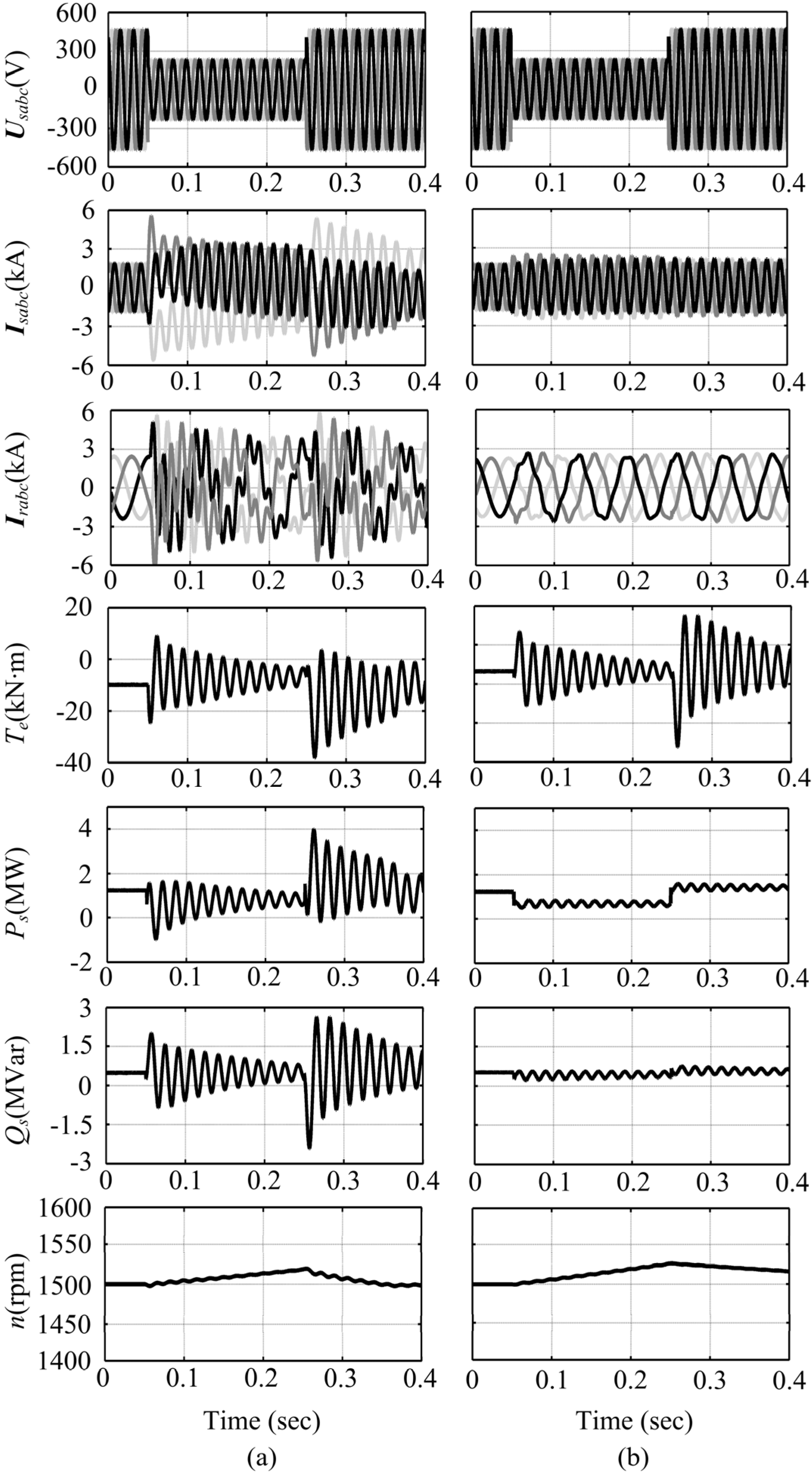
4.2. Phase-Phase-Ground Fault

Figure 12 shows the simulation results with the conventional and the proposed control strategies adopted separately, when the stator voltage drops to 0.3 pu under a phase-phase-ground fault in the grid. The grid voltage dips at 0.05 s and recovers at 0.25 s. Not only does the stator flux have a transitory dc component, such as that originated in symmetrical dips, but it also has a permanent negative sequence component that remains throughout the whole dip, causing a continuous over-current in rotor. As for the traditional control scheme, a continuous over-current appears in both the stator and rotor during the grid fault. Therefore, the protection system should be enabled during the whole process to protect the converter. The wind turbine generator will be disconnected from the grid affecting the grid fault recovery. The proposed control scheme can suppress the rotor fault current caused by the dc and negative sequence components of the state flux linkage without affecting the performance of the DFIG.

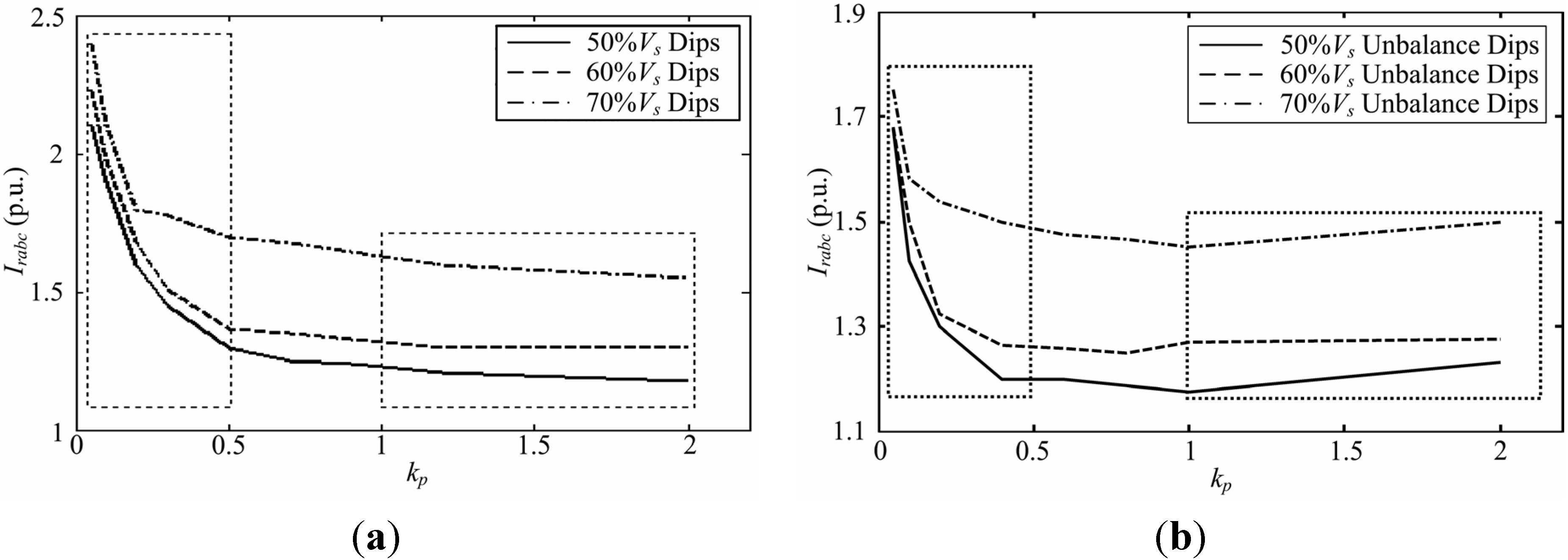
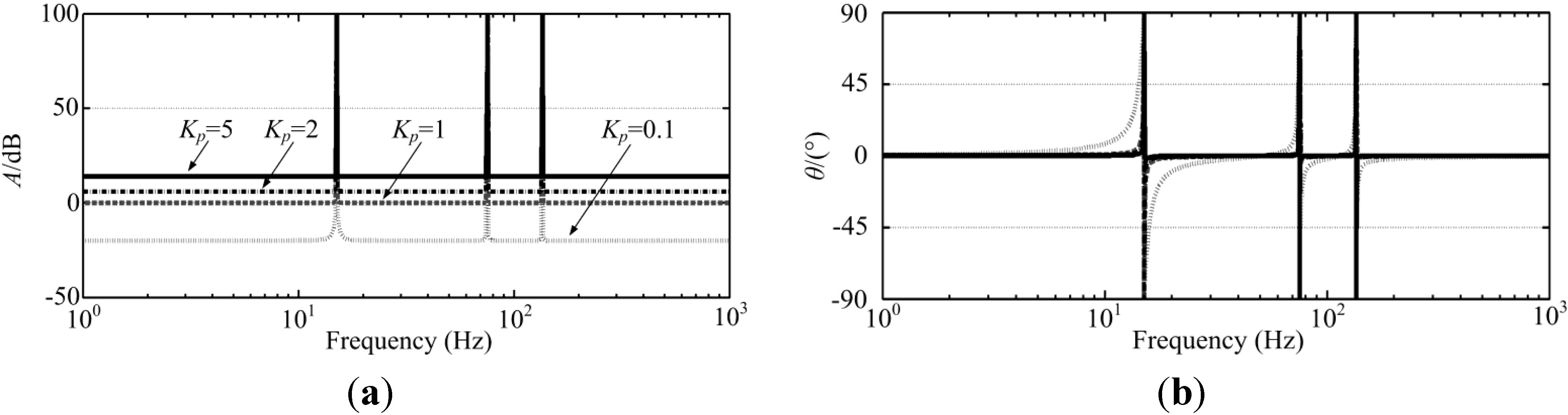
4.3. Control System Analysis

The effect of the controller on a fault current is directly affected by the voltage rating of the RSC. In the normal operation of the DFIG, the RSC output voltage is approximately sVs [23]. If the magnetizing current is neglected, rotor and stator currents are the same in pu values. DFIG slip is supposed to range from −0.3 to 0.3, which means that the RSC needs to output at least 30% of the stator voltage in pu. Therefore, the rating of the RSC should be 30% of the stator rating at the minimum. In practice, in order to enhance the ability to regulate transient current, RSC ratings will be higher than 30%.
The fault in the paper is supposed to be a three-phase grid fault for the sake of convenience. As a result of stator voltage dips, the dc component φsDC is generated in the stator flux linkage to maintain conservation which compensates for the flux caused by the dip voltage of Vf. This is equivalent to the static voltage Vf generated in space with the angular speed of ωr relative to the rotor. Therefore, Vf will have an effect of (1−s)Vf on rotor. To keep the rotor current constant, the supplied rotor voltage of RSC under voltage dips is:
V r = | s | V s + ( 1 s ) V f
Assuming that the stator voltage is 1 pu, Figure 13 shows the compensation voltage required by the RSC under voltage dips of different levels. As shown in Figure 13, the required maximum voltage of RSC is 0.3 pu under normal conditions. The deeper the voltage dips, the higher the compensation voltage rating that will be required. Compensation voltage of the RSC reaches 1.34 pu if the dip is 80% Vs.
Figure 13. The required output voltage of the RSC under different voltage drop levels.
Energies 05 04758 g013
The relationship between the required compensation voltage for RSC and the rotor speed under grid fault is illustrated in Figure 14, which is cut by an auxiliary horizontal plane Vr = 0.6 pu. The faster the rotor speed is, the higher the compensation voltage for RSC required under the same condition is. The compensation voltage reaches the maximum when the DFIG is operated at the maximum super-synchronous speed (s = −0.3). If the stator voltage further drops to 0 V, the required rotor voltage of RSC needs to be 1.6 pu. In Figure 14, Vr = 0.6 pu represents the maximum output voltage of the RSC under which the RSC is capable of totally eliminating the transient rotor current. Due to the IGBT restrictions, the pulse current rating of the IGBT is typically twice as high as the continuous current rating. Therefore, when the rotor voltage is 0.6 pu, the LVRT of DFIG can operate in a much wider region than that under the surface of Vr = 0.6 pu which means that the LVRT of DFIG can be realized under all conditions, even if the output voltage of the RSC is not at the maximum value of 1.6 pu.
In order to suppress the rotor fault current of the DFIG under grid fault conditions, two main problems need to be solved: accurate detection of the rotor angular frequency and selection of control parameters. The rotor current of tuned frequency can be controlled by setting resonant frequency of the PR controller. Inaccurate detection of grid angular frequency or rotor rotating angular frequency have an impact on the control precision of the PR controller.
Figure 14. Feasible regions depending on the maximum output voltage of the RSC.
Energies 05 04758 g014
To study the controller performance under a large detection error, simulation analysis of the proposed control scheme is conducted during the three-phase stator voltage drop to 0.2 pu and the two-phase stator voltage drop to 0.2 pu, respectively. Assuming that the actual generator angular frequency is ωr, the angular frequency is detected to be ωr − 20.
Figure 15. The effect of detection signal on the peak of rotor current. (a) 80% three-phase-to-ground fault; (b) 80% phase-phase-to-ground fault.
Energies 05 04758 g015
Figure 15 shows the effect of detection signal on the peak of rotor current under grid fault conditions. Figure 15(a) shows that the difference of the maximum fault currents before and after the addition of the detection error is 0.04 pu when the three-phase stator voltage drops to 0.2 pu. Figure 15(b) shows that the difference of the maximum fault currents before and after the addition of detection error is 0.05 pu when the two-phase stator voltage drops to 0.2 pu. It can be drawn from Figure 15(a) and Figure 15(b) that the controller can suppress rotor fault currents under both symmetric and asymmetric grid fault conditions when the detected angular frequency is inaccurate.
The auxiliary controller should suppress rotor over-currents when grid faults occur. The parameters of the auxiliary controller affect the regulated performance of the rotor current. Bode plot of controller is shown in Figure 16. It can be seen that the bigger the kp is, the bigger controller gain on other bands, leading to the interference between different frequencies which will further affect the system stability when the amplification gain is up to a certain extent. Therefore, to ensure system stability and good control performance, the kp value should not be too large.
Figure 16. Bode diagram of PR controller with variation of kp.
Energies 05 04758 g016
The simulation results on the DFIG system with different values of kp under the 50%, 60%, and 70% of three-phase stator voltage dips, respectively, are shown in Figure 17(a). As shown, when kp is less than 0.5, the rotor over-current is markedly inhibited by the increase of the kp value.
Figure 17. The effect of kp on the peak of rotor current. (a) three-phase-to-ground fault; (b) phase-phase-to-ground fault.
Energies 05 04758 g017
However, when kp is more than 1.0, the rotor over-current does not change significantly with the increase of the kp value. Figure 17(b) shows the effect of kp on the peak of rotor current under two-phase stator voltage dip conditions. When kp is less than 0.5, the rotor over-current is significantly inhibited with the increase of the kp value. However, when kp is more than 1.0, the rotor over-current peak slightly increases under 50% and 70% two-phase stator voltage dips with the increase of the kp value. This is because when the kp value reaches a certain extent, controller will produce a gain on other frequencies, which will cause the mutual influence of current with different frequencies, directly affecting over-current suppression.

5. Conclusions

This paper presents a proportional resonance control scheme for a DFIG-based wind power generation system under great-level grid fault conditions. The control system consisting of auxiliary controllers suppresses rotor fault currents effectively, requiring no decomposition or extraction of dc and negative sequence components of the rotor current which improves the response speed of the controller. Therefore, the proposed scheme reduces the occurrence of crowbar interruptions and enhances the operational capability of the DFIG wind turbine. The relationships between the RSC voltage ratings, the rotor speed, and the LVRT capability of the DFIG system are analyzed. With limited RSC voltage ratings, the rotor fault currents of specified frequencies are eliminated to a great extent. The controller performs well, even when the angular frequency detection is not accurate. Simulations have been presented under symmetric and asymmetric grid fault conditions to confirm the analysis and verify the proposed control method. It can be drawn from the simulations that by using the proposed PR scheme the DFIG experiences less rotor fault current and remains in service to continuously supply active/reactive power to grid under grid fault conditions.

Nomenclature

Us, Ur
Stator and rotor voltage vectors.
Is, Ir
Stator and rotor current vectors.
ψs, ψr
Stator and rotor flux linkage vectors.
ωs, ωr
Stator and rotor angular frequencies.
Ls, Lr
Stator and rotor self inductances.
Lls, Llr
Stator and rotor leakage inductances.
Lm
Mutual inductance.
Rs, Rr
Stator and rotor resistances

Subscripts

α, β
Stationary αβ axis.
s, r
Stator, rotor.
+, DC,−
Positive, DC and negative components.
0, 1, 2
Positive, DC and negative components in rotor αr βr reference frame.

Superscripts

r
Rotor αr βr reference frames.
*
Reference value for controller.

Acknowledgments

The authors are grateful to the National Key Basic Research Program of China (973 Program) under Grant 2013CB035602, the Key Program of National Natural Science Foundation of China (51037004), and National Natural Science Foundation of China (51107084) for supporting this work.

References

  1. Yamamoto, M.; Motoyoshi, O. Active and reactive power control for doubly-fed wound rotor induction generator. IEEE Trans. Power Electron. 1991, 6, 624–629. [Google Scholar] [CrossRef]
  2. Xia, C.L.; Song, Z.F. Wind energy in China: current scenario and future perspectives. Renew. Sustain. Energy Rev. 2009, 13, 1966–1974. [Google Scholar] [CrossRef]
  3. Pak, L.F.; Dinavahi, V. Real-time simulation of a wind energy system based on the doubly-fed induction generator. IEEE Trans. Power Syst. 2009, 24, 1301–1309. [Google Scholar] [CrossRef]
  4. Slootweg, J.G.; de Haan, S.W.H.; Polinder, H.; Kling, W.L. General model for representing variable speed wind turbines in power system dynamics simulations. IEEE Trans. Power Syst. 2003, 18, 144–151. [Google Scholar] [CrossRef]
  5. Akagi, H.; Sato, H. Control and performance of a doubly-fed induction machine intended for a flywheel energy storage system. IEEE Trans. Power Electron. 2002, 17, 109–116. [Google Scholar] [CrossRef]
  6. Xu, L.; Yao, L.; Sasse, C. Grid integration of large DFIG-based wind farms using VSC transmission. IEEE Trans. Power Syst. 2007, 22, 976–984. [Google Scholar] [CrossRef]
  7. Hughes, F.M.; Anaya-Lara, O.; Jenkins, N.; Strbac, G. Control of DFIG-based wind generation for power network support. IEEE Trans. Power Syst. 2005, 20, 1958–1966. [Google Scholar] [CrossRef]
  8. Xia, C.L.; Gu, X.; Shi, T.N.; Yan, Y. Neutral-Point potential balancing of three-level inverters in direct-driven wind energy conversion system. IEEE Trans. Energy Convers. 2011, 26, 18–29. [Google Scholar] [CrossRef]
  9. Mullane, A.; Lightbody, G.; Yacamini, R. Wind-turbine fault ridethrough enhancement. IEEE Trans. Power Syst. 2005, 20, 1929–1937. [Google Scholar] [CrossRef]
  10. Ng, C.; Ran, L.; Bumby, J. Unbalanced-grid-fault ride-through control for a wind turbine inverter. IEEE Ind. Appl. 2008, 44, 845–856. [Google Scholar] [CrossRef]
  11. Zhou, Y.; Bauer, P.; Ferreira, J.A.; Pierik, J. Operation of grid-connected DFIG under unbalanced grid voltage condition. IEEE Trans. Energy Convers. 2009, 24, 240–246. [Google Scholar] [CrossRef]
  12. Song, Z.F.; Xia, C.L.; Shi, T.N. Assessing transient response of DFIG based wind turbines during voltage dips regarding main flux saturation and rotor deep-bar effect. Appl. Energy 2010, 87, 3283–3293. [Google Scholar] [CrossRef]
  13. Causebrook, A.; Atkinson, D.J.; Jack, A.G. Fault ride-through of large wind farms using series dynamic braking resistors. IEEE Trans. Power Syst. 2007, 22, 966–975. [Google Scholar] [CrossRef]
  14. Morren, J.; de Haan, S.W.H. Ride-through of wind turbines with doubly-fed induction generator during a voltage dip. IEEE Trans. Energy Convers. 2005, 20, 435–441. [Google Scholar] [CrossRef]
  15. Petersson, A.; Harnefors, L.; Thiringer, T. Evaluation of current control methods for wind turbines using doubly-fed induction machines. IEEE Trans. Power Electron. 2005, 20, 227–235. [Google Scholar] [CrossRef]
  16. Morren, J.; de Haan, S.W.H. Short-circuit current of wind turbines with doubly fed induction generator. IEEE Trans. Energy Convers. 2007, 22, 174–180. [Google Scholar] [CrossRef]
  17. Brekken, T.A.; Mohan, N. Control of a doubly fed induction wind generator under unbalanced grid voltage conditions. IEEE Trans. Energy Convers. 2007, 22, 129–135. [Google Scholar] [CrossRef]
  18. Xu, L.; Wang, Y. Dynamic modeling and control of DFIG based wind turbines under unbalanced network conditions. IEEE Trans. Power Syst. 2007, 22, 314–323. [Google Scholar] [CrossRef]
  19. Xu, L. Enhanced control and operation of DFIG-based wind farms during network unbalance. IEEE Trans. Energy Convers. 2008, 23, 1073–1081. [Google Scholar] [CrossRef]
  20. Hu, J.B.; Xu, L. Improved control of DFIG systems during network unbalance using PI–R current regulators. IEEE Trans. Ind. Electron. 2009, 56, 439–451. [Google Scholar] [CrossRef]
  21. Xiang, D.; Ran, L.; Tavner, P.J.; Yang, S. Control of a doubly fed induction generator in a wind turbine during grid fault ride-through. IEEE Trans. Energy Convers. 2006, 21, 652–662. [Google Scholar] [CrossRef]
  22. Hu, J.B.; He, Y.K.; Xu, L. Improved rotor current control of wind turbine driven doubly-fed induction generators during network voltage unbalance. Electr. Power Syst. Res. 2010, 80, 847–856. [Google Scholar] [CrossRef]
  23. Liang, J.; Qiao, W.; Harley, R.G. Feed-forward transient current control for low-voltage ride-through enhancement of DFIG wind turbines. IEEE Trans. Energy Convers. 2010, 25, 836–843. [Google Scholar] [CrossRef]
  24. Teodorescu, R.; Blaabjerg, F.; Liserre, M.; Loh, P.C. Proportional–resonant controllers and filters for grid-connected voltage-source converters. IEEE Proc. Electr. Power Appl. 2006, 153, 750–762. [Google Scholar] [CrossRef]
  25. Zmood, D.N.; Holmes, D.G. Stationary frame current regulation of PWM inverters with zero steady-state error. IEEE Trans. Power Electron. 2003, 18, 814–822. [Google Scholar] [CrossRef]
  26. Chen, W.; Chen, C.; Song, Z.F. Proportional-resonant control for dual PWM converter in doubly fed wind generation system. Proc. CSEE 2009, 29, 1–7. [Google Scholar]
  27. Timbus, A.; Liserre, M.; Teodorescu, R.; Rodriguez, P.; Blaabjerg, F. Evaluation of current controllers for distributed power generation systems. IEEE Trans. Power Electron. 2009, 24, 654–664. [Google Scholar] [CrossRef]
  28. Liu, C.J.; Blaabjerg, F.; Chen, W.J.; Xu, D.H. Stator current harmonic control with resonant controller for doubly fed induction generator. IEEE Trans. Power Electron. 2012, 27, 3207–3220. [Google Scholar] [CrossRef]
  29. Fadaeinedjad, R.; Moallem, M.; Moschopoulos, G. Simulation of a wind turbine with doubly fed induction generator by FAST and Simulink. IEEE Trans. Energy Convers. 2008, 23, 690–700. [Google Scholar] [CrossRef]

