1. Introduction
To help solve energy problems and mitigate global warming, the importance of clean, renewable energy is growing. In addition, in order to prevent massive blackouts caused by disasters, small distributed energy systems have been and continue to be tested. In this testing, there has been an increase in the variety of technologies used to generate clean, renewable energy.
Of the clean, renewable energy generation methods, wind power generation, which can be conducted over the ocean, is attracting increasing attention. However, wind power generation has the following disadvantages: low output compared to thermal and nuclear power generation, noise, bird strikes, and landscape disturbances. Gilbert and Foreman [
1] examined a diffuser-augmented wind turbine (DAWT) as a part of their research on high-power wind turbines. A DAWT is a wind turbine in which the power is augmented by concentrating the wind energy using a diffuser. We have developed a unique wind turbine with a brimmed diffuser called a “Wind-Lens turbine” [
2,
3]. An example of this turbine is shown in
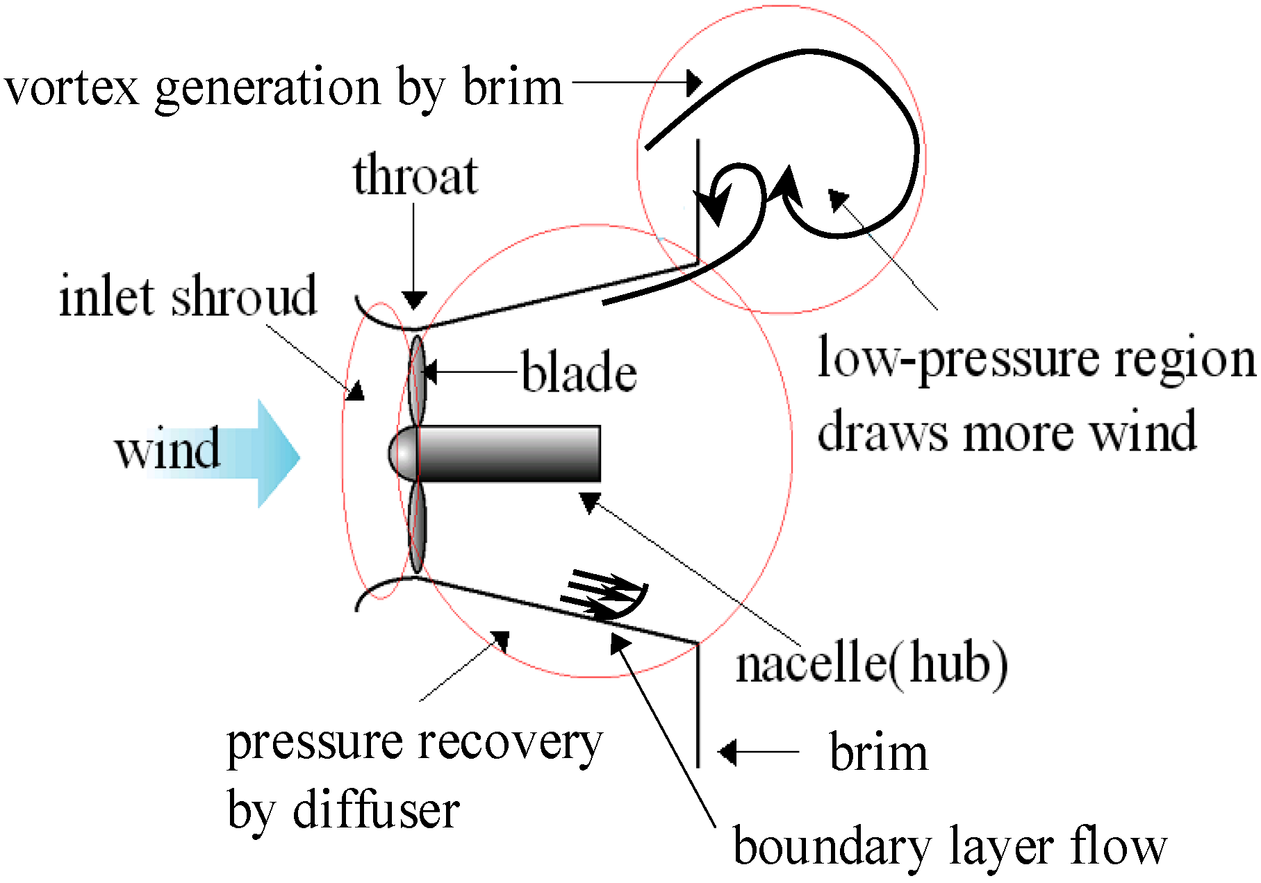
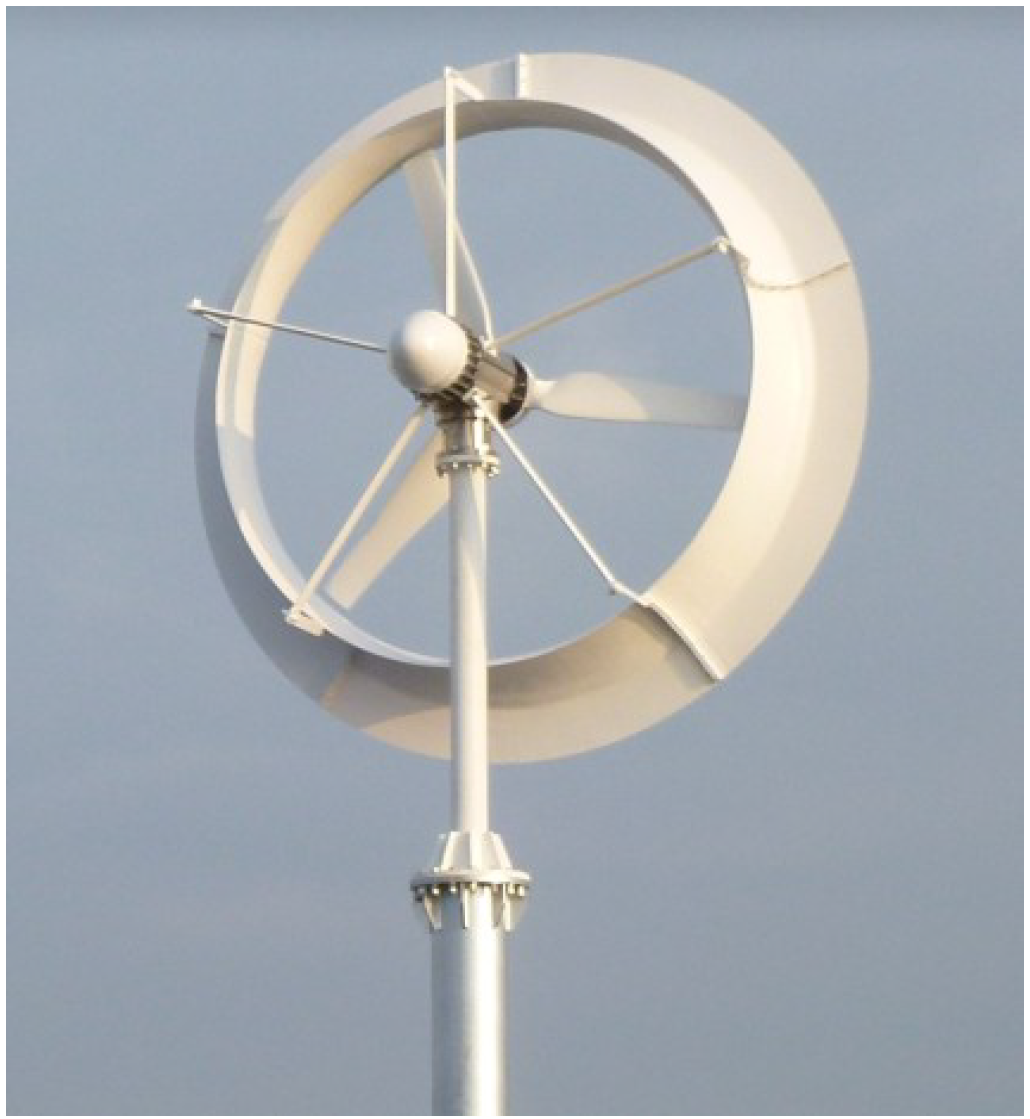
Figure 1. A Wind-Lens turbine consists of a downwind type wind turbine and a structure composed of an inlet shroud, a diffuser, and a brim. The flow which passes inside the diffuser and the flow which comes around behind the brim generate a large vortex behind the structure, as shown in
Figure 2. As a result of this very low-pressure region, air is drawn into the turbine at a higher rate and accelerates more than in the case with a bare wind turbine. Due to this effect, a 3 kW turbine with a rotor diameter of 2.5 m generates 2.5 times more power with a Wind-Lens than the same turbine without a Wind-Lens.
Figure 1.
Wind-Lens turbine (rated power of 3 kW at 11 m/s wind speed).
Figure 1.
Wind-Lens turbine (rated power of 3 kW at 11 m/s wind speed).
Figure 2.
Characteristics of flow around a Wind-Lens turbine.
Figure 2.
Characteristics of flow around a Wind-Lens turbine.
In addition to increased power output, a Wind-Lens turbine offers the following advantages: low noise, reduced number of bird strikes, and reduced landscape disturbance. Our research group’s previous studies reported the power increase of Wind-Lens turbines [
2,
3]. In this paper, we focus on the low aerodynamic noise of Wind-Lens turbines.
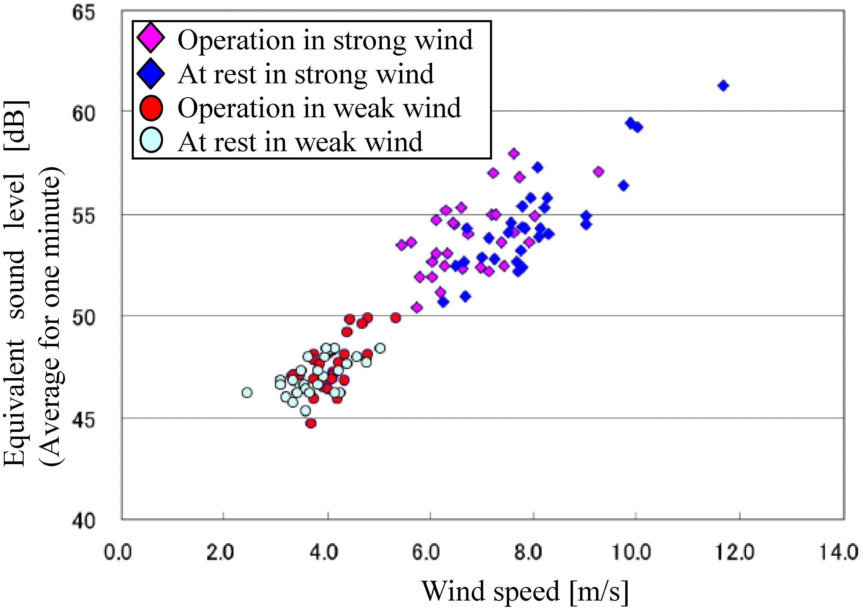
Figure 3 shows an example of a noise survey based on an international standard for measuring noise generated by wind turbines, JIS C1400-11 (IEC 61400-11). There is no appreciable difference in the noise level between a Wind-Lens turbine in operation and one at rest [
4]. There are many sources of wind turbine noise including (1) turbulent boundary layer trailing edge noise; (2) laminar boundary layer vortex shedding noise; (3) boundary layer separation noise; and (4) noise associated with blade tip vortex formation [
5]. In particular, blade tip vortices can strongly contribute to wind turbine noise over a broad band of high frequencies [
6,
7]. In this paper, we focus on blade tip vortices in a Wind-Lens turbine since the blades of a Wind-Lens turbine are enclosed by the Wind-Lens structure and thus the circumstance of the blade tips in a Wind-Lens turbine is quite different from that of the blade tips on a bare wind turbine. Therefore, we conducted numerical simulations of the flow around a Wind-Lens turbine, paying special attention to the behavior of the blade tip vortices.
Figure 3.
An example of a noise survey for a Wind-Lens turbine [
4].
Figure 3.
An example of a noise survey for a Wind-Lens turbine [
4].
Numerical simulations of the flow around a Wind-Lens turbine have been conducted previously, however, almost all of these simulations used the Reynolds-averaged Navier-Stokes (RANS) technique. This numerical technique modeled a wind turbine as a simple resistance in the inflow direction [
8,
9]. For an unsteady 3D direct numerical simulation, an actuator-disk model for a wind turbine was devised to simulate the drag and rotational forces exerted on the fluid by the wind turbine [
10]. A revised version of the actuator-disk model, an actuator-line model, represented the blades as rotating lines [
11]. However, these models cannot simulate the details of the flow around a wind turbine such as the flow around a whole blade under rotation, the flow separation at the blade trailing edge, and the blade tip vortices. Therefore, in the present paper, we use a moving boundary technique in the CFD model to simulate the flow around the rotating blades.
2. Numerical Simulation Method
Numerical simulations are conducted with the commercial CFD software STAR-CCM+, in which a finite-volume method and LES are used to solve the Navier–Stokes equations. The WALE model [
12] is used as the subgrid-scale model in the LES. As mentioned above, we use a moving boundary technique in the present study. In this technique, the simulation region is divided into a static region and a rotating region. Data on the fluid flow, such as velocity and pressure data, are transferred between the static and rotating regions through the interface between them at every time step. A first-order implicit method is used for the time marching method. A second-order upwind scheme is applied to the convective term.
Table 1 shows the simulation conditions.
The Reynolds number is defined as Re = DU∞/ν, where D is the diameter of the wind turbine rotor, U∞ is the uniform inflow speed, and ν is the dynamic viscosity. The blade tip speed ratio is defined as λ = ωR/U∞, where ω is the angular frequency of rotation of the blades and R is the radius of the wind turbine rotor. As for the boundary conditions, velocity is constant at the inflow boundary, pressure is constant at the outflow boundary, free-slip conditions are imposed at the far-field boundaries, and no-slip conditions are imposed on the surface of objects.
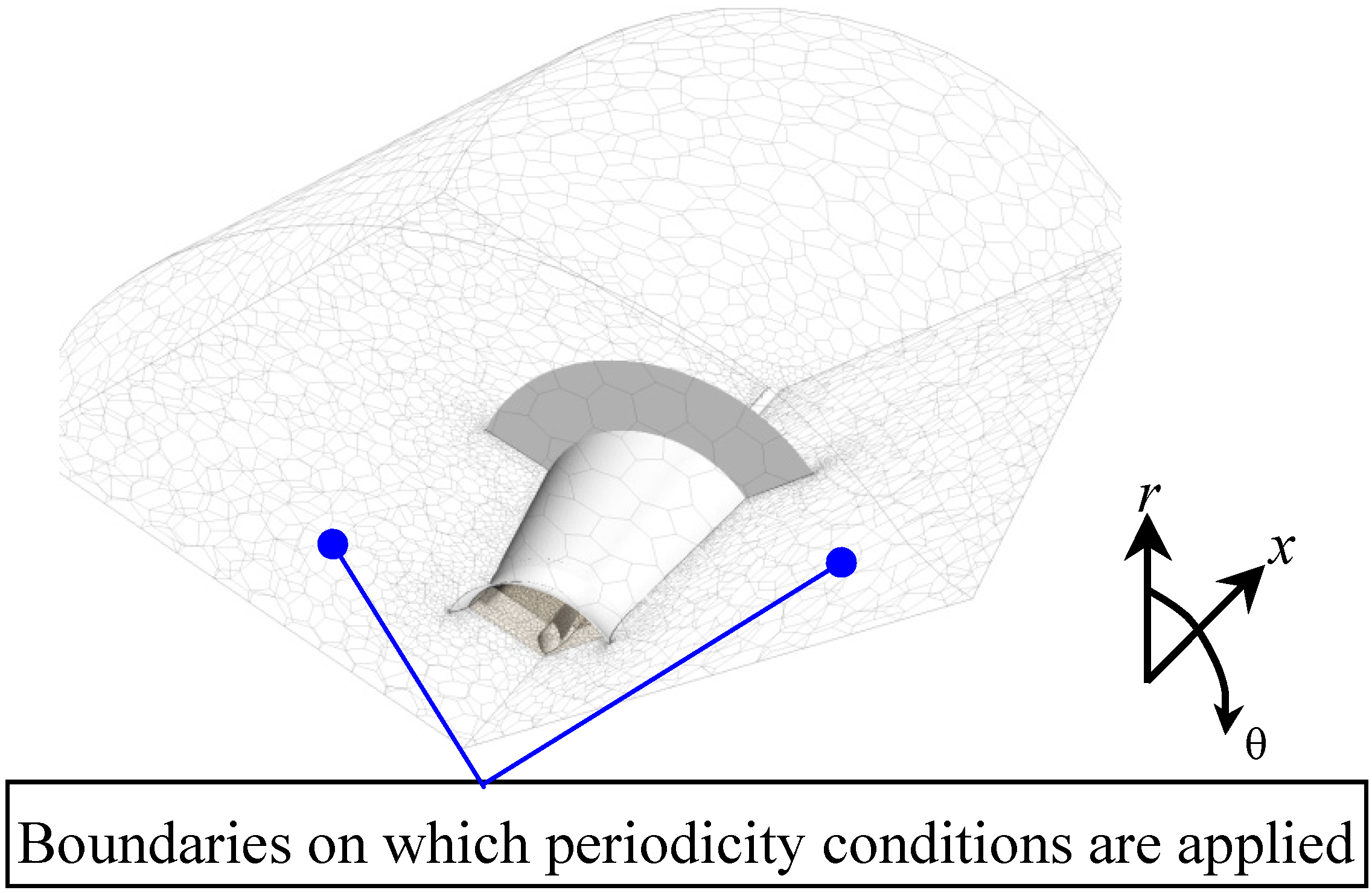
Since there are three blades in a symmetrical configuration, we simulate one third of the rotor area and assume the periodicity condition on the boundaries indicated by blue dots in
Figure 4. It should be noted that the numbers of cells in
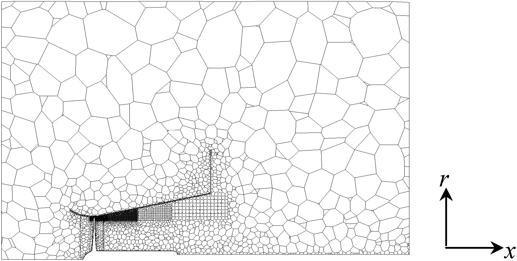
Table 1 are not enough to simulate the whole fields with high accuracy and more cells should be required. To simulate the behavior of the blade tip vortices, however, we concentrated the cells around the area between the blade tip and the inside wall and in the near downstream, as seen in
Figure 5. Therefore the numerical simulation results in the present research show a good qualitative agreement with past wind tunnel experiments.
Figure 4.
Simulation region of the long-type Wind-Lens turbine. x: inflow direction; r: radial direction; θ: circumferential direction.
Figure 4.
Simulation region of the long-type Wind-Lens turbine. x: inflow direction; r: radial direction; θ: circumferential direction.
Figure 5.
Calculation mesh for the long-type Wind-Lens turbine in an x-r cross-section. x: inflow direction; r: radial direction.
Figure 5.
Calculation mesh for the long-type Wind-Lens turbine in an x-r cross-section. x: inflow direction; r: radial direction.
Table 1.
Simulation conditions.
Table 1.
Simulation conditions.
| Type of wind turbine (see Figure 6) | Long-type wind-Lens turbine | Compact-type Wind-Lens turbine | Bare wind turbine |
|---|
| For simulation of the blade tip vortices | For comparison with the bare wind turbine |
|---|
| Reynolds number | 1.65 × 10⁵ | 7.98 × 10⁵ | 7.98 × 10⁵ |
| Blade tip speed ratio | 4.5 | 4.0 | 4.0 |
| Time step | 3 × 10⁻⁵ | 3 × 10⁻⁴ | 1 × 10⁻³ | 1 × 10⁻³ |
| Number of cells | 1,983,513 | 1,918,566 | 759,310 | 551,829 |
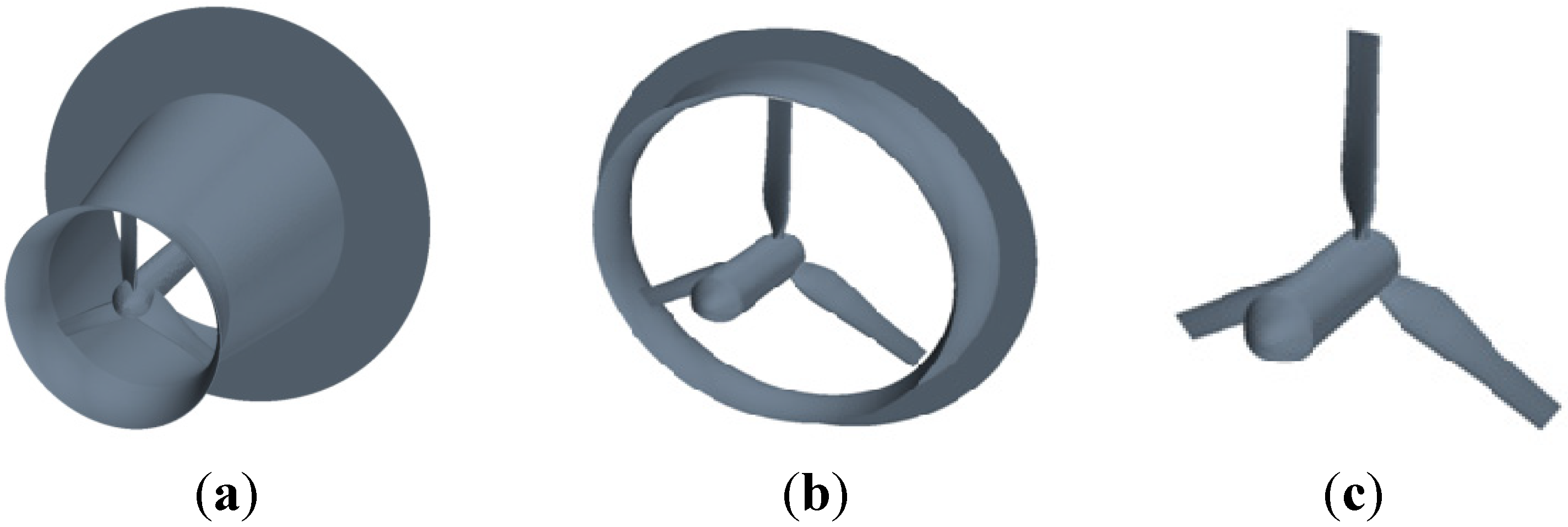
Figure 6 shows the objects considered in the simulations: (a) a long-type Wind-Lens turbine, which incorporates an elongated diffuser; (b) a compact-type Wind-Lens turbine; and (c) a bare wind turbine.
Figure 7 and
Table 2 show the configuration parameters of the Wind-Lens turbines. The configuration of the bare wind turbine is the same as that of the compact-type Wind-Lens turbine without the brimmed-diffuser shroud. As shown in
Table 1, there are two calculation conditions for the compact-type Wind-Lens turbine: one condition is adopted to focus on the blade tip vortices and the other condition is adopted to focus on the differences between a bare wind turbine and a compact-type Wind-Lens turbine. Examples of the simulation region and mesh are shown in
Figure 4 and
Figure 5. In these figures, the simulation region and mesh are shown for the long-type Wind-Lens turbine.
Table 2.
Parameters for the configurations of the Wind-Lens turbines.
Table 2.
Parameters for the configurations of the Wind-Lens turbines.
| Type of Wind-Lens | Long-type | Compact-type |
|---|
| Type of blade | NACA | MEL |
| Diameter of the throat (Dt) | 400 mm | 2560 mm |
| Diameter of the rotor (D) | 380 mm | 2500 mm |
| Diameter of the hub (Dh) | 88 mm | 360 mm |
| Diffuser length (L) | 500 mm | 351 mm |
| Inlet length + Diffuser length (Lt) | 600 mm | 576 mm |
| Height of the brim (h) | 200 mm | 256 mm |
| Tip clearance (s) | 10 mm | 30 mm |
| Semi-open angle (θ) | 12° | - |
Figure 6.
Objects considered in the simulations: (a) long-type Wind-Lens turbine; (b) compact-type Wind-Lens turbine; (c) bare wind turbine.
Figure 6.
Objects considered in the simulations: (a) long-type Wind-Lens turbine; (b) compact-type Wind-Lens turbine; (c) bare wind turbine.
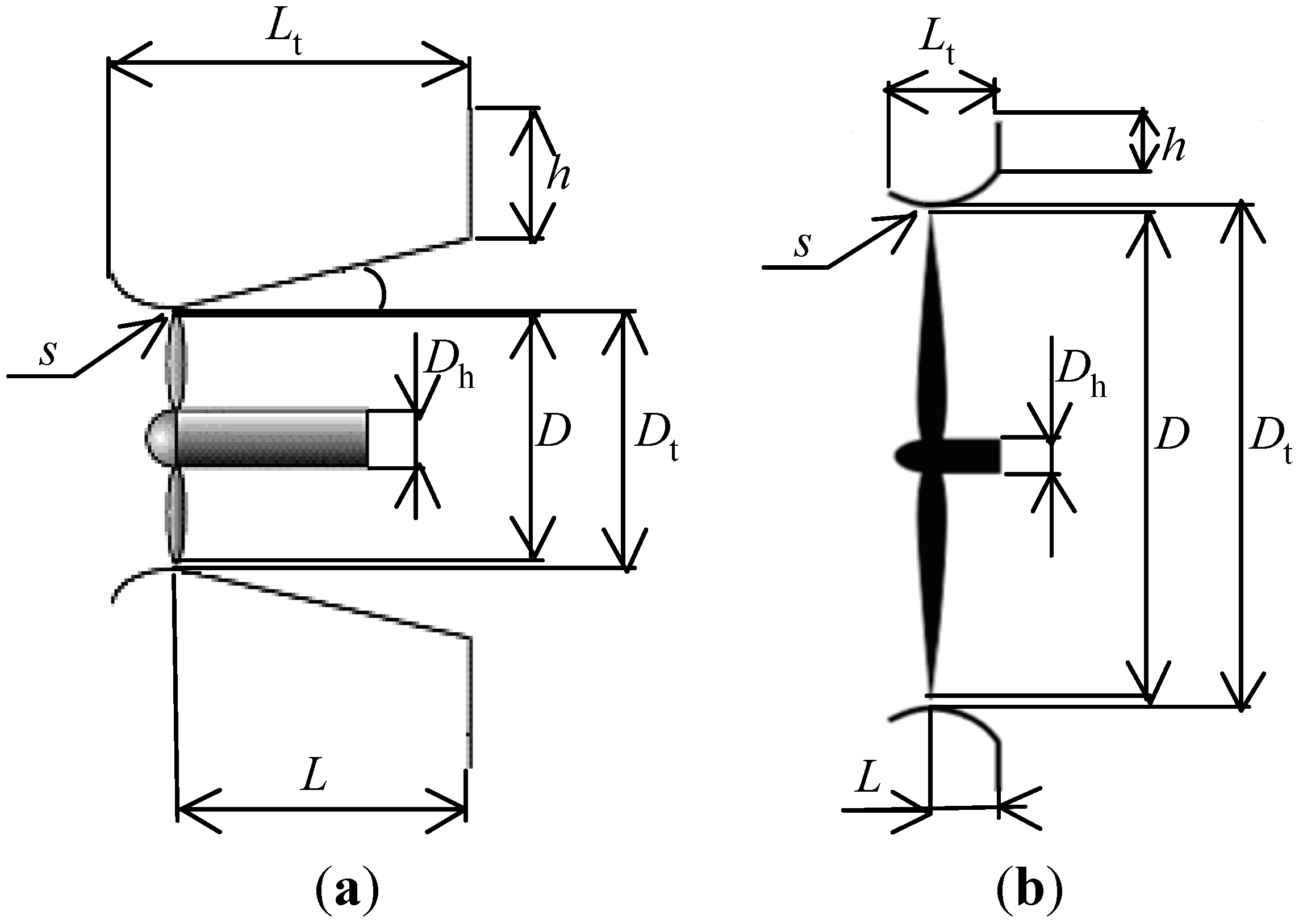
Figure 7.
Configurations of Wind-Lens turbines: (
a) long-type, (
b) compact-type. See
Table 2 for definitions of the symbols used in the figure.
Figure 7.
Configurations of Wind-Lens turbines: (
a) long-type, (
b) compact-type. See
Table 2 for definitions of the symbols used in the figure.
3. Simulation Results for the Flow around the Blade Tip of a Long-Type Wind-Lens Turbine
A simulation of the flow around the blade tip of a long-type Wind-Lens turbine is conducted.
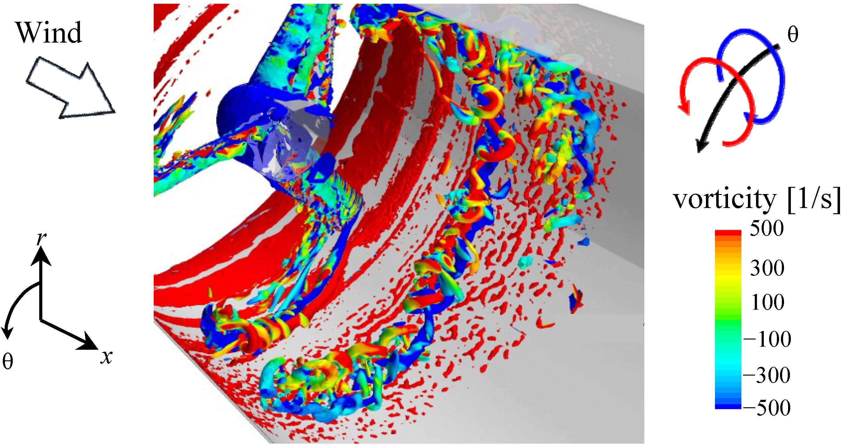
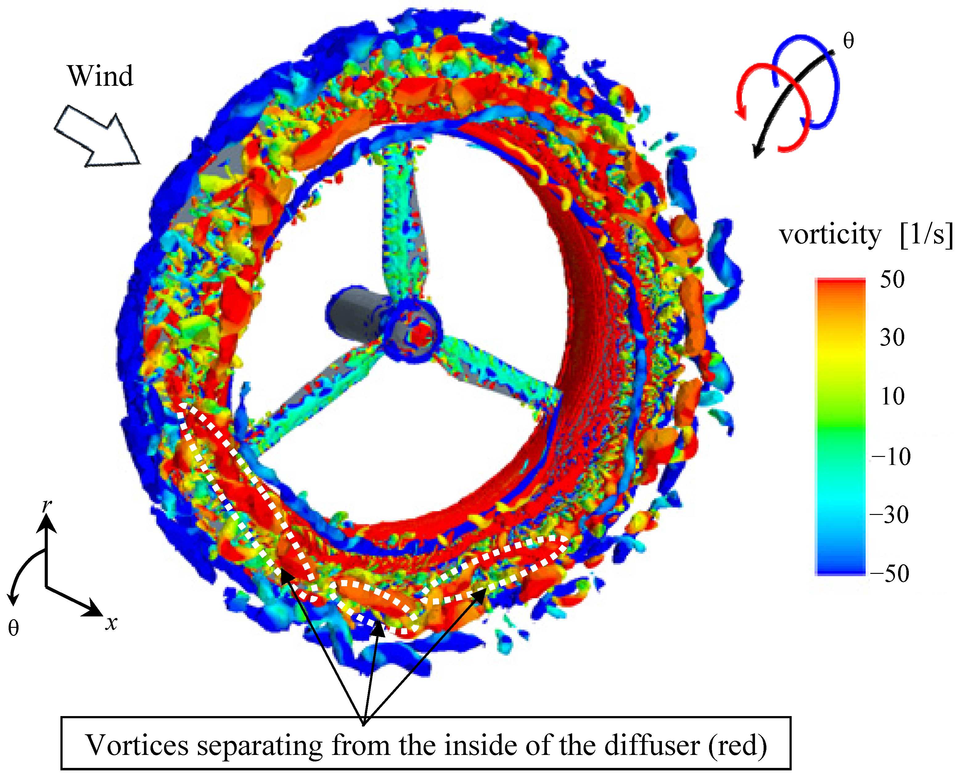
Figure 8 shows the vortex structures from this simulation. The circumferential vortices are identified using the λ
2 identification method [
13]. In
Figure 8, the vortices are colored based on the circumferential direction of the vorticity. The vortices colored in blue are those which flow from the upstream side of the blade tip to the downstream side. These vortices are blade tip vortices since they come around from the upstream side of the blade to the downstream side of the blade. A strong counter-rotating vortex structure (red in
Figure 8) is generated alongside the blade tip vortex between the blade tip and the inner surface of the diffuser. This counter-rotating vortex is probably induced by the interaction of the tip vortex and the inner surface of the diffuser. These vortex structures are qualitatively consistent with those observed in the wind tunnel experiment performed by Sato
et al. [
14] as seen in
Figure 9. This experiment was reported by Abe
et al. [
15].
Figure 8 shows that, although the blade tip vortex and the induced vortex are in alignment at first, eventually the induced vortex is partially rolled up by the blade tip vortex. Further downstream, the blade tip vortex also rolls up and forms a helical structure with the induced vortex. The blade tip vortex and the induced vortex are mutually weakened in this process and dissipate before they reach the end of the diffuser.
Figure 8.
Simulation results for the long-type Wind-Lens turbine: θ-component of the vorticity inside a long-type Wind-Lens turbine. x: inflow direction; r: radial direction; θ: circumferential direction.
Figure 8.
Simulation results for the long-type Wind-Lens turbine: θ-component of the vorticity inside a long-type Wind-Lens turbine. x: inflow direction; r: radial direction; θ: circumferential direction.
Figure 9.
Wind tunnel experimental results for the long-type Wind-Lens turbine: θ-component of the vorticity inside a long-type Wind-Lens turbine [
14].
Figure 9.
Wind tunnel experimental results for the long-type Wind-Lens turbine: θ-component of the vorticity inside a long-type Wind-Lens turbine [
14].
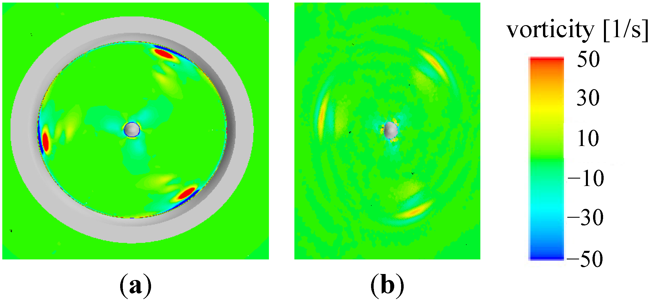
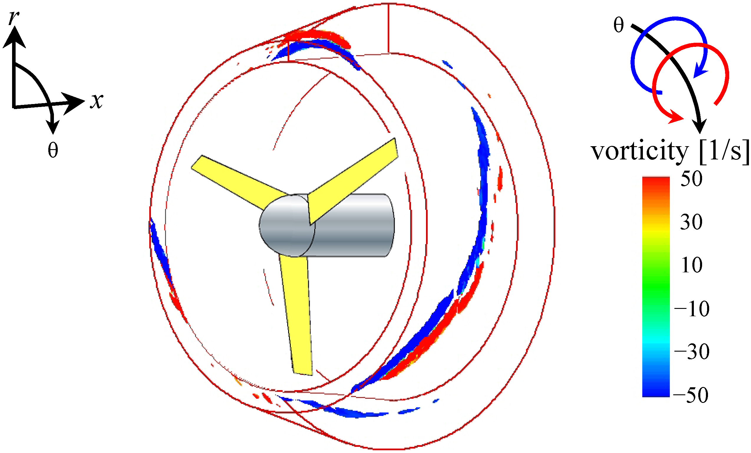
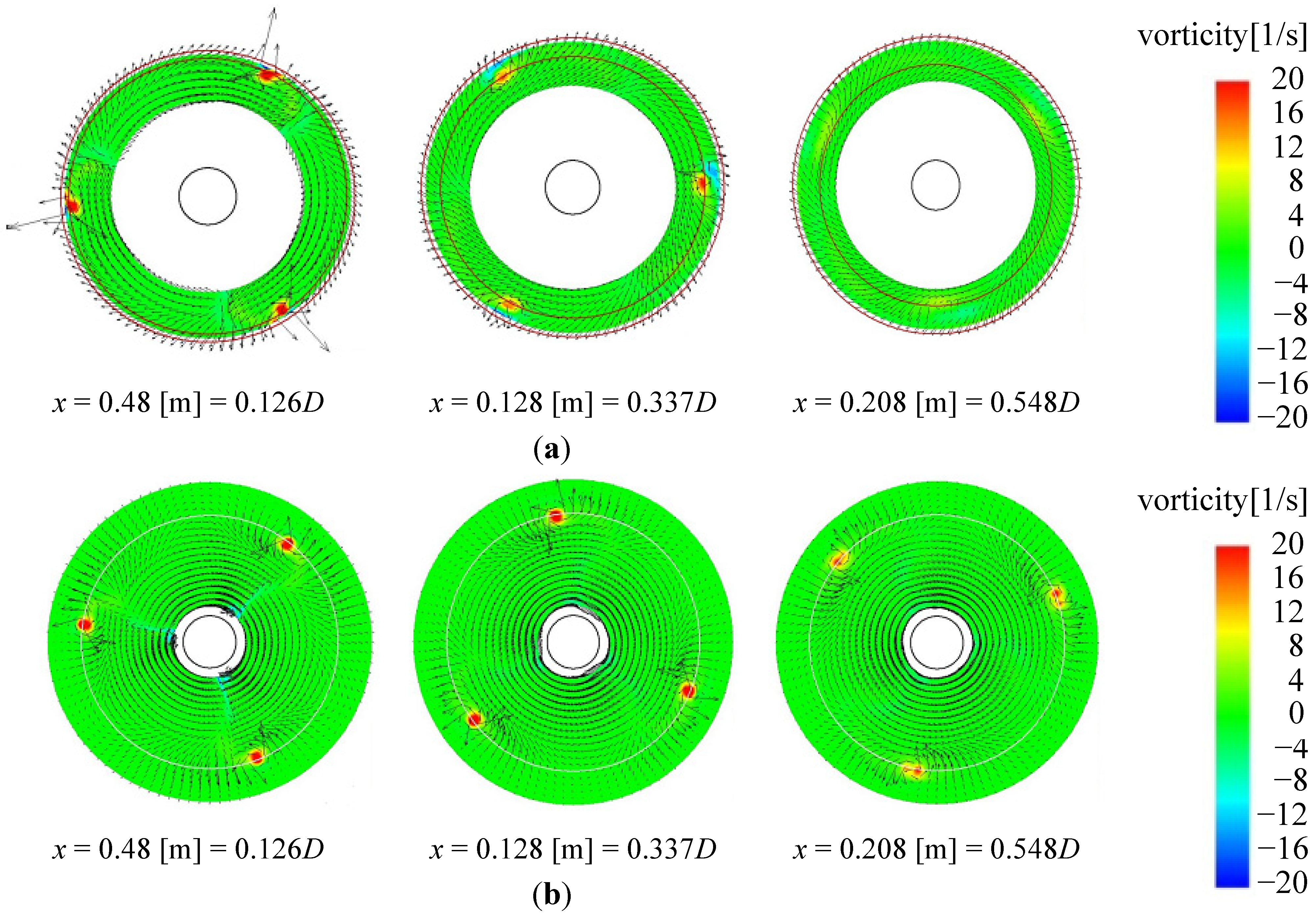
The behavior of these vortices is qualitatively consistent with results from wind tunnel experiments as shown in
Figure 10a [
14,
16]. For comparison,
Figure 10b shows the vortices observed in the same wind tunnel experiments for the bare wind turbine. In the wind tunnel experiments, the configuration of the bare turbine was the same as that of the long-type Wind-Lens turbine without the diffuser shroud. Furthermore, the Wind-Lens turbine used in the wind tunnel experiments was identical to that used in the present simulation. The arrows in
Figure 10 represent the flow velocity. In the wind tunnel experiments, conditional sampling was used to identify the mean vorticity field while the blades were rotating. Similar to the numerical results, induced vortices with counter-vorticity appeared between the blade tips and the inner surface of the diffuser in the wind tunnel experiments, as seen in the middle panel of
Figure 10a. Downstream, the tip vortices became very weak in the case with the brimmed-diffuser shroud (
Figure 10a) in comparison to the tip vortices in the case without the shroud (
Figure 10b), which is also qualitatively consistent with the results of the present study as will be described in
Section 4.2.
Figure 10.
(
a) Wind tunnel experimental results for the long-type Wind-Lens turbine:
x-component of the vorticity (colors) and velocity (vectors) in
r-θ cross-sections; (
b) Same as
Figure 10a except for the bare wind turbine [
14,
16].
Figure 10.
(
a) Wind tunnel experimental results for the long-type Wind-Lens turbine:
x-component of the vorticity (colors) and velocity (vectors) in
r-θ cross-sections; (
b) Same as
Figure 10a except for the bare wind turbine [
14,
16].
In addition, in case of the bare wind turbine, the shapes of the blade tip vortices in the middle panel of
Figure 10b are almost same as that in the upstream side as seen in the left panel of
Figure 10b. However, in case of the long-type Wind-Lens turbine, the shapes of the blade tip vortices in the middle panel of
Figure 10a are different from that in the upstream side as seen in the left panel of
Figure 10a. This result of the long-type Wind-Lens turbine suggests that the blade tip vortices are interfered with by the induced vortices.
Subsequently, the behavior of these vortex structures is examined in detail.
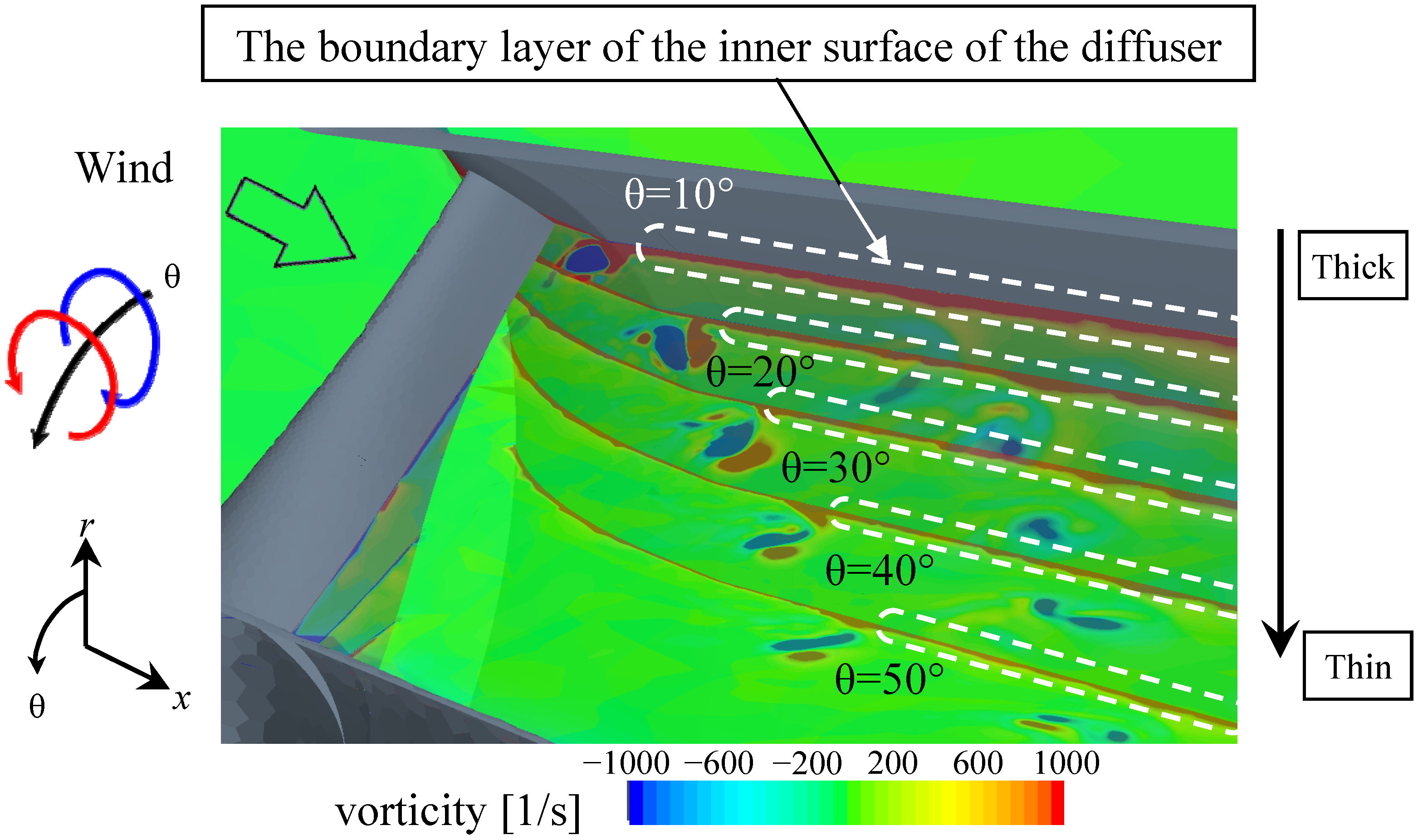
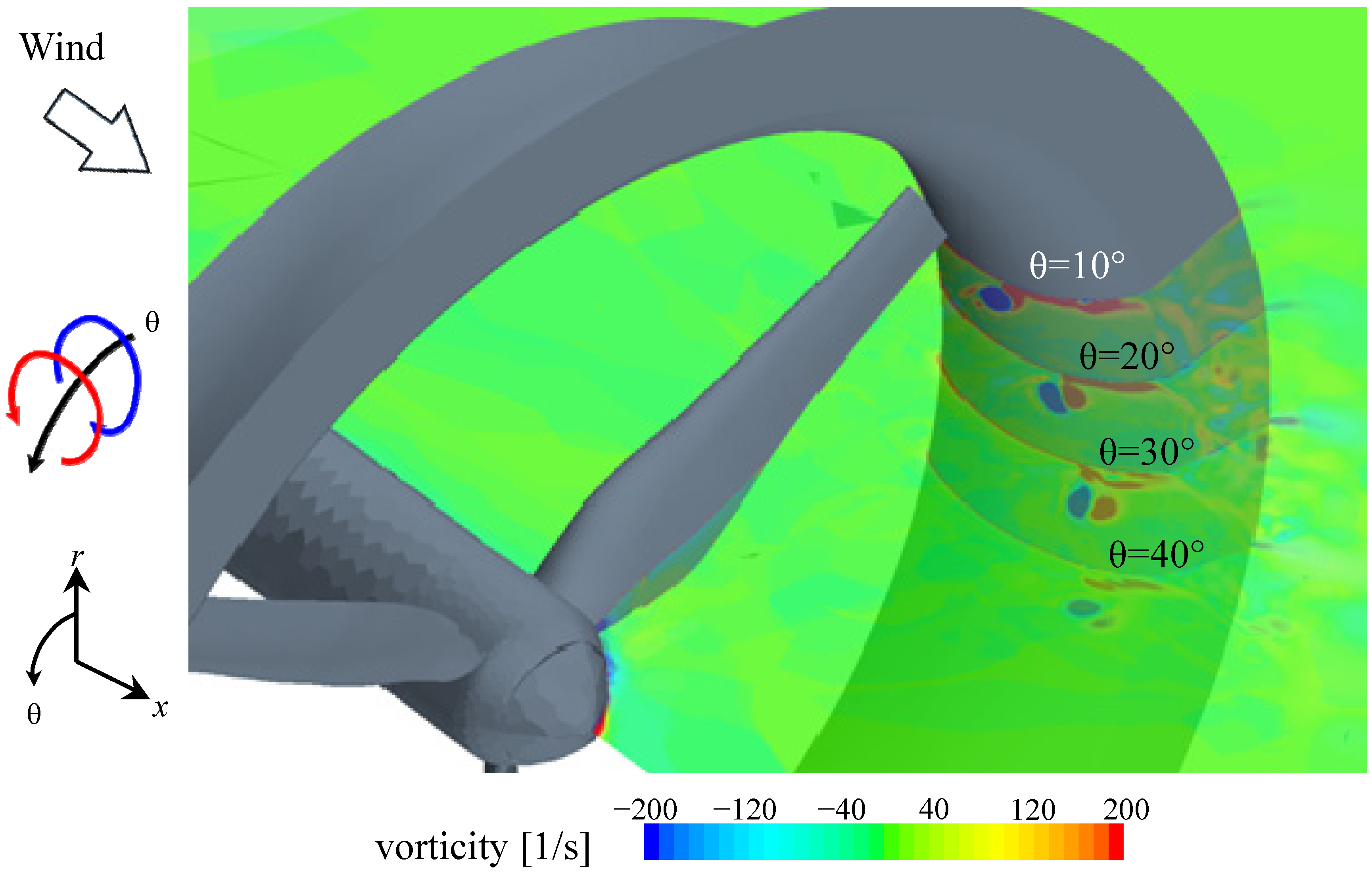
Figure 11 shows a contour plot of the circumferential vorticity at θ = 10°, 20°, 30°, 40°, and 50° of separation from the blade’s leading edge. The induced vortex (red) is likely generated by the blade tip vortex (blue) within the boundary layer of the inner surface of the diffuser, as shown for θ = 10°. From θ = 10° to 50°,
i.e., as the blade rotates away from a particular position on the inner surface of the diffuser, the boundary layer over that position becomes thinner. The thinning of the boundary layer likely occurs as a result of the generation of the induced vortex. This thinning of the boundary layer in turn suppresses flow separation from the inner surface of the diffuser. Because the flow separation is suppressed, the pressure recovery from the diffuser entrance to the exit improves, which contributes to the Wind-Lens turbine’s ability to efficiently collect and accelerate the incoming flow. Although blade tip vortices are a source of noise and a cause of power loss for wind turbines, these vortices may contribute to the improvement of the collection and acceleration of the incoming flow observed in Wind-Lens turbines.
Figure 11.
θ-component of the vorticity inside the long-type Wind-Lens turbine including that of the blade tip vortex and the counter-rotating vortex.
Figure 11.
θ-component of the vorticity inside the long-type Wind-Lens turbine including that of the blade tip vortex and the counter-rotating vortex.


