Characteristic Evaluation on the Cooling Performance of an Electrical Air Conditioning System Using R744 for a Fuel Cell Electric Vehicle

Abstract
:1. Introduction
2. Experimental Setup and Data
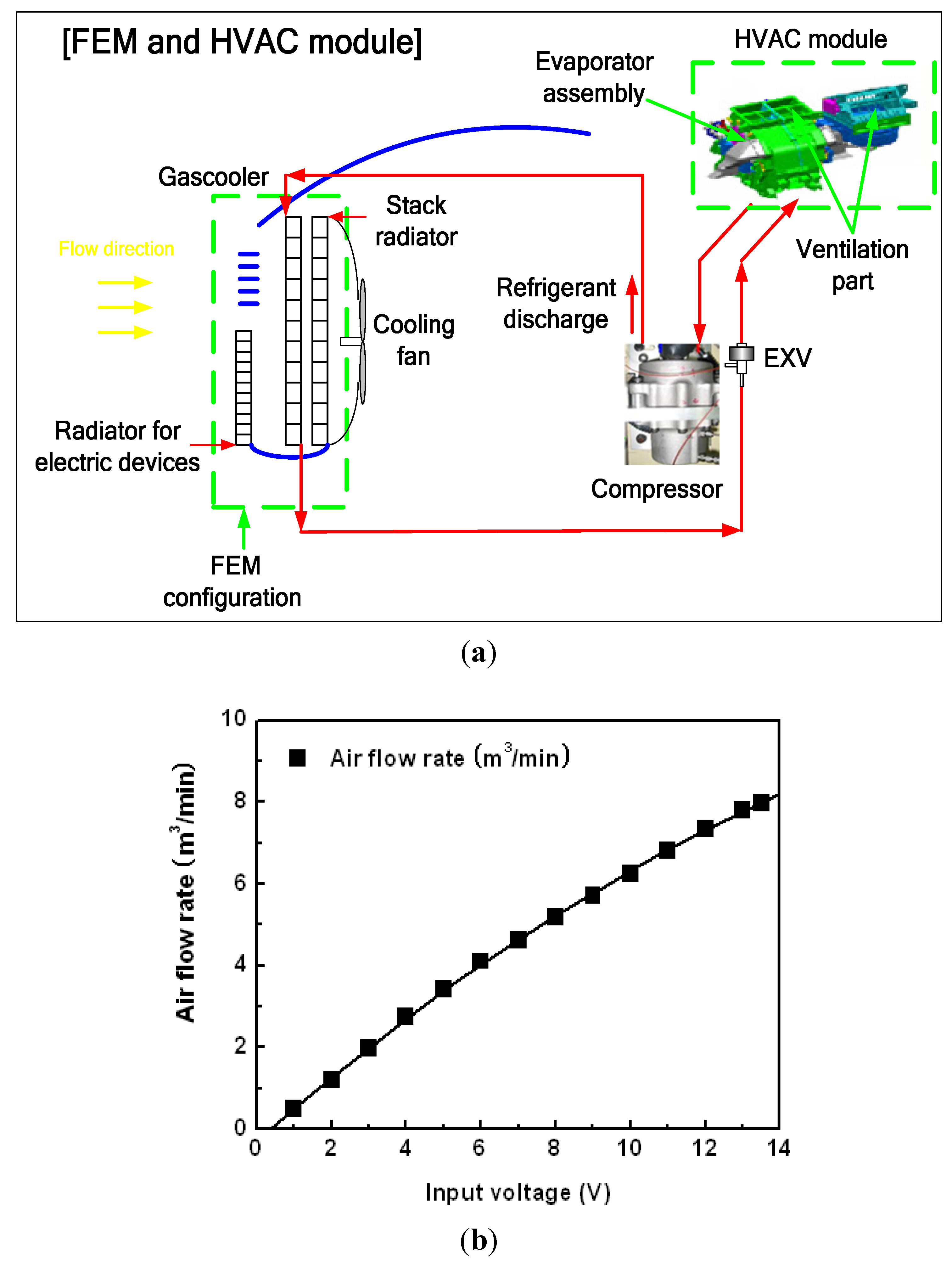
2.1. Test Setup
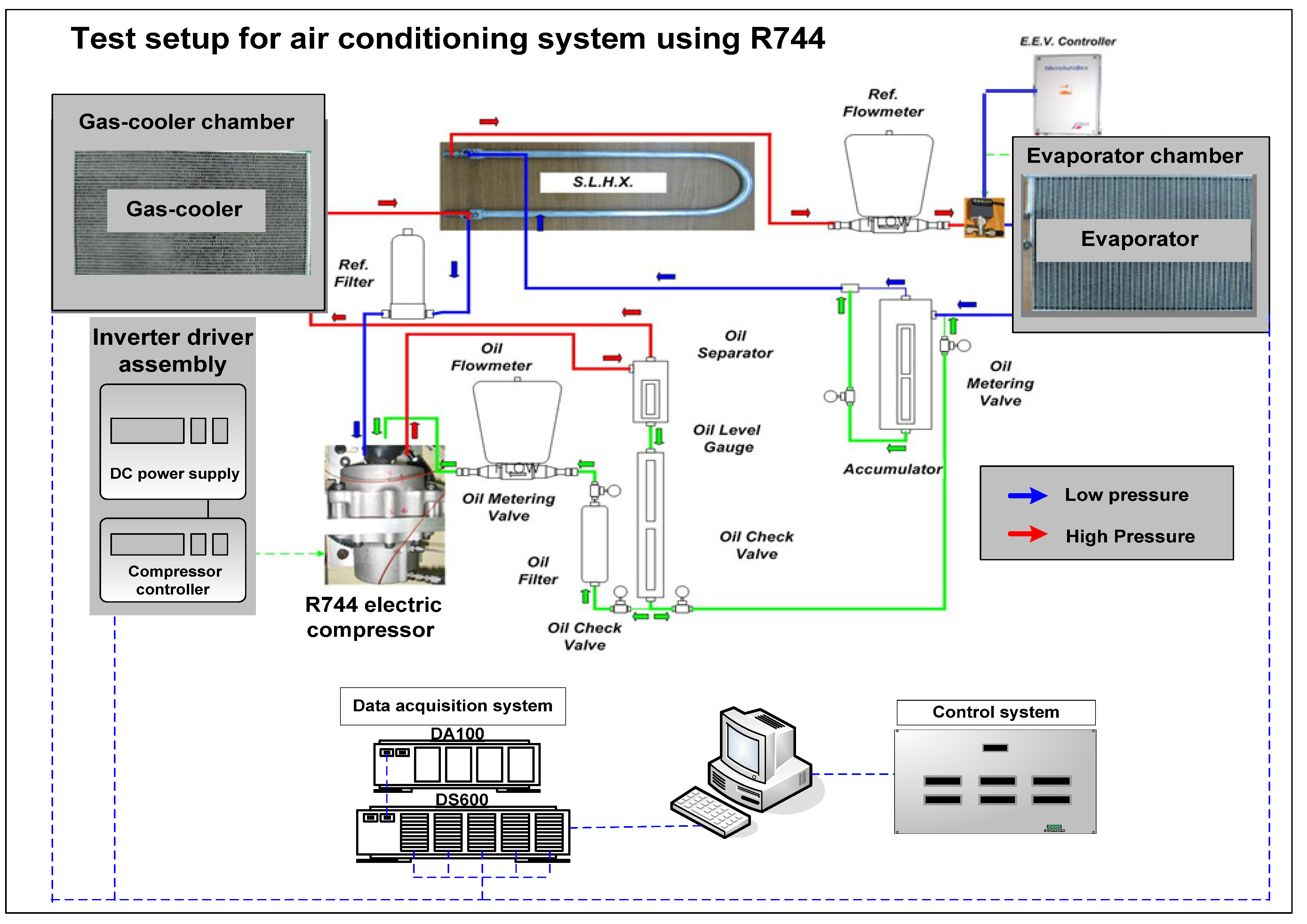

| Components | Specifications | |
|---|---|---|
| Stack capacity of the fuel cell electric vehicle | Capacity (kW) | 80.0 |
| Evaporator (Interior heat exchanger) | Capacity (kW) | 5.0 at 4 m3/min and 6000 rpm |
| Type, core size (mm3) | Multi-flow type, W 250 × H 260 × D 35 | |
| Gas cooler (Exterior heat exchanger) | capacity (kW) | 7.5 at 4 m/s, 35 °C and 6000 rpm |
| Type, core size (mm3) | Multi-flow type, W 630 × H 375 × D 16 | |
| Internal heat exchanger | Capacity (kW) | 0.5~1.5 at 2 m/s and 6000 rpm |
| Type, length (mm) | Co-axial, 750~1250 | |
| Compressor | Type | Electric driven compressor |
| Displacement (cc/rev) | 7.5 | |
| Expansion valve | Type | Electronic control (PWM) |
| Flow rate (kg/h) | 50~250 | |
| Accumulator | Pressure (bar) | Max. 125 at 90 °C |
| Volume (cc) | 550 | |
| Components | Conditions |
|---|---|
| Compressor speed (RPM) | 3000, 4000, 5000, 6000 |
| Vgas cooler, in (m/s) | 2.0, 4.0 |
| Tgas cooler, in (°C) | 27.0, 35.0, 42.0 |
| Rhevaporator (%) | 50.0 |
| Tevaporator, in (°C) | 27.0, 35.0, 42.0 |
| Qevaporator, in (m3/min) | 4.0, 7.0 |
| Items | Accuracy |
|---|---|
| Thermocouples (T-type) | ±0.1 °C |
| Pressure gage (Sensors, PI3H) | ±0.1% (Max. 250 bar) |
| Mass flow meter (Coriolis type) | ±0.15%, Max. 680 kg/h |
| Data logger (Gantner) | E. Gate IP (V3) (2.93W @ 12.06 V) |
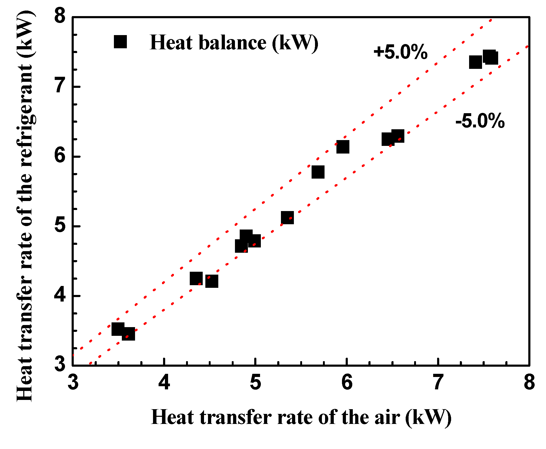
| Cooling capacity | 4.5% |
| Cooling COP | 5.8% |
2.2. Data Reduction
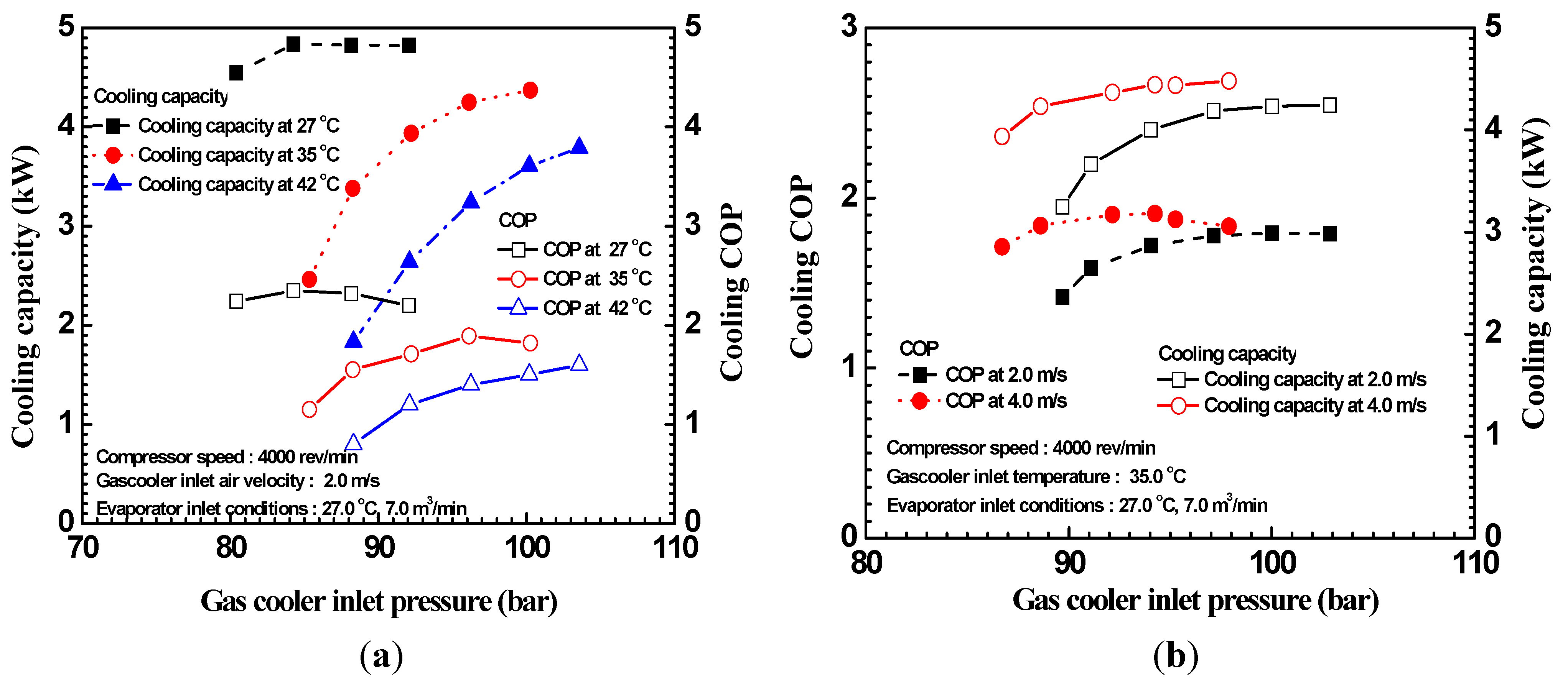
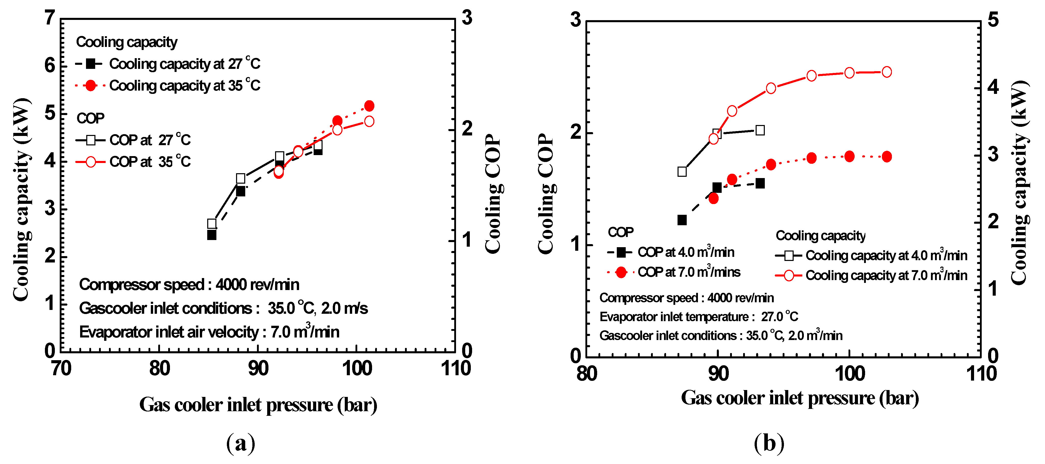
3. Results and Discussion


4. Conclusions
- (1)
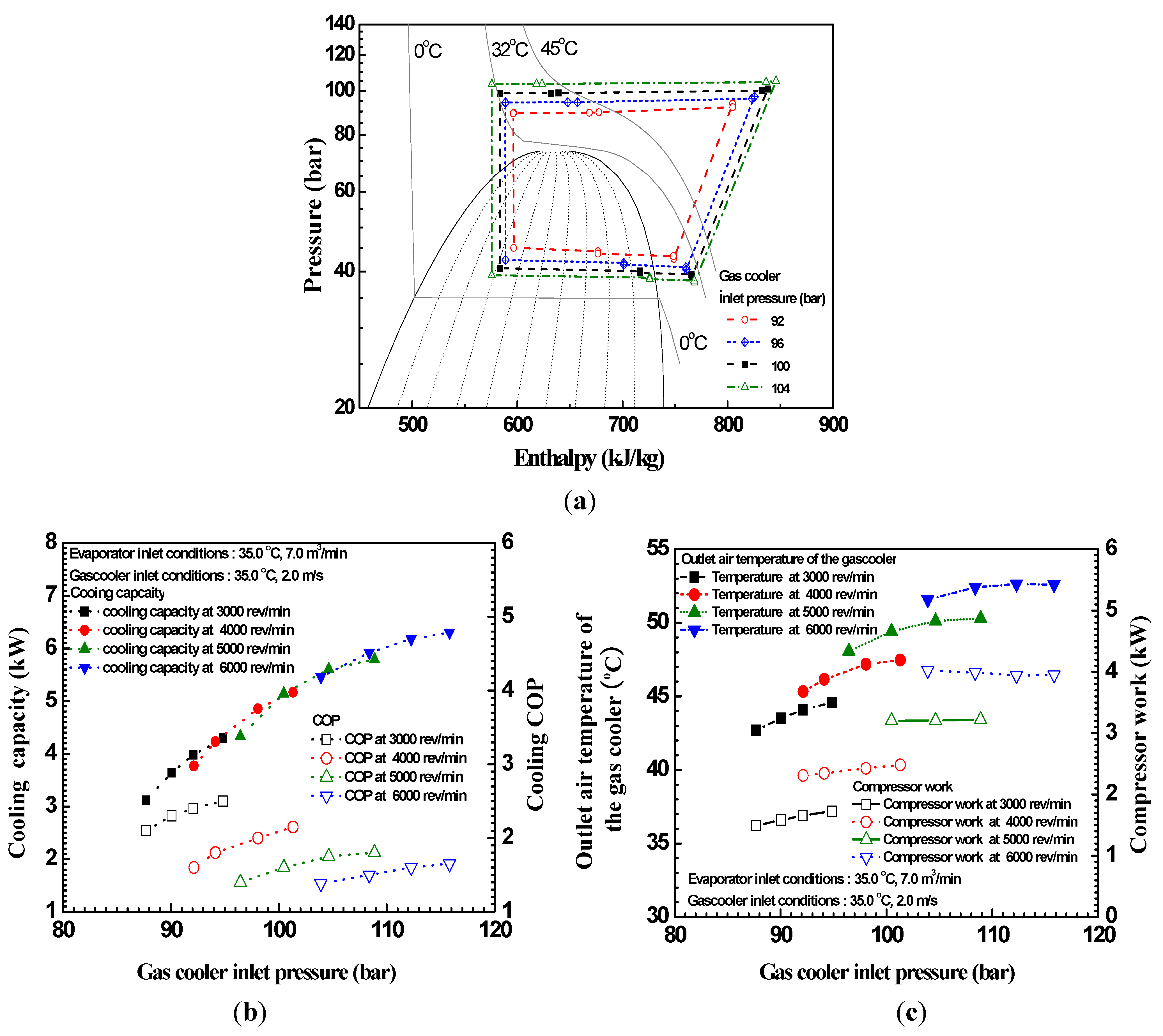
- The cooling COP and the cooling capacity increased by 30.3% up to 2.5 and 36.8% up to 6.4 kW, respectively, with the rise of the gas cooler inlet pressure from 92.0 bar to 102.0 bar at the gas cooler inlet temperature of 35.0 °C and the compressor speed of 4000 rev/min.
- (2)
- The cooling capacity increased with rise of the compressor speed but the cooling COP was reduced because the compressor work increased due to the increased compression ratio and specific volume at the compressor inlet.
- (3)
- At the gas cooler inlet pressure of 90.0 bar, the cooling COP and the cooling capacity decreased by 55.6% and 55.1%, respectively, with the rise of the gas cooler air inlet temperature from 27 °C to 42 °C due to the decreased heat transfer efficiency of the gas cooler.
- (4)
- Under extremely hot weather conditions over 35.0 °C, the cooling capacity of the tested system was sufficient, over 5.0 kW, at the compressor speed over 4500 rev/min.
- (5)
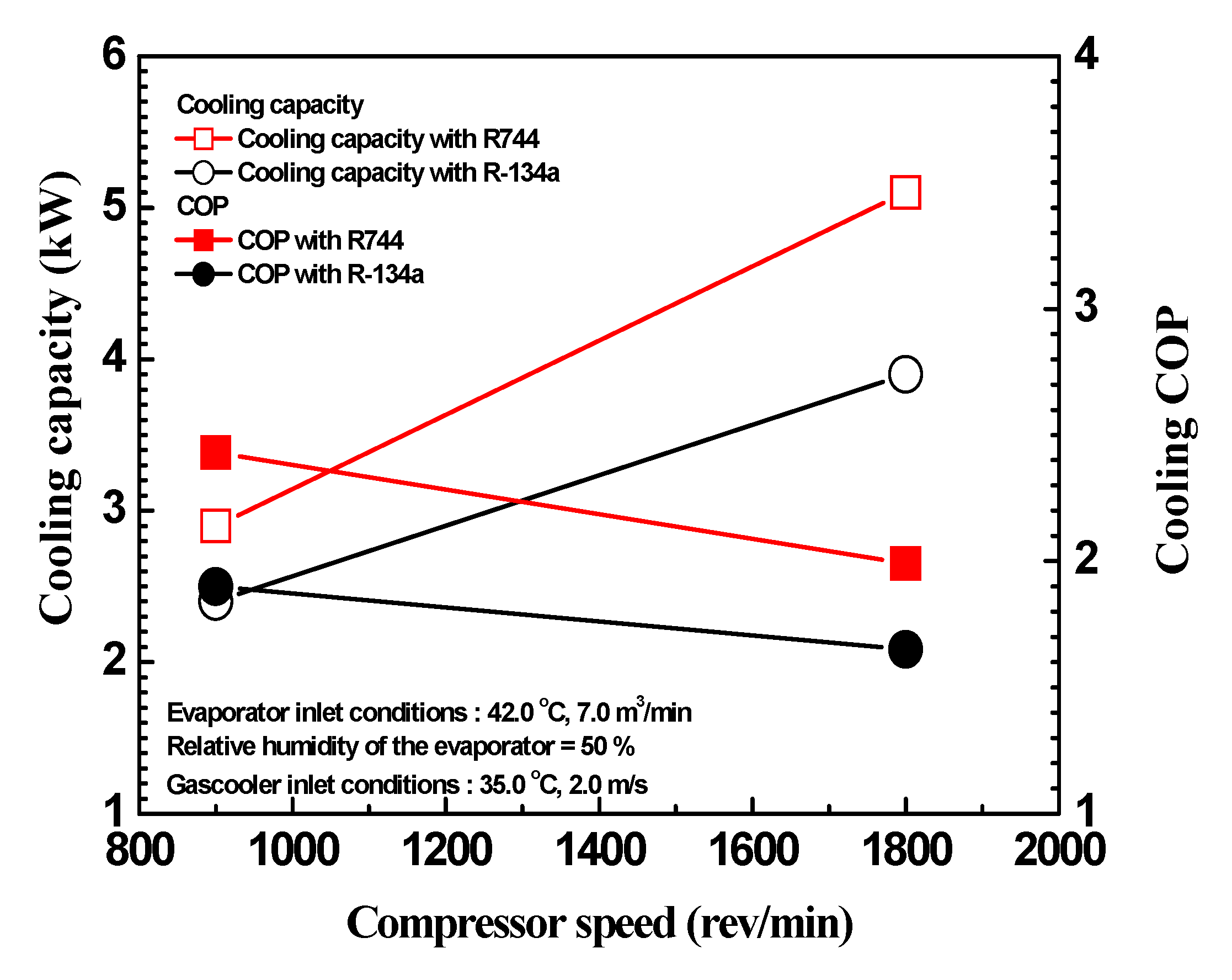
- The cooling COP of the electrical air conditioning system using R744 was on average 24.3% higher than that using R-134a at all compressor speeds.
Nomenclature
| COP | Coefficient of performance |
| FEM | Front end module |
| h | Enthalpy (kJ/kg) |
Mass flow rate (kg/h) | |
Heat transfer rate (W) | |
| RPM | Revolution per minute (rev/min) |
| Rh | Relative humidity (%) |
| T | Temperature (°C) |
| V | Velocity (m/s) |
Subscripts
| A | air |
| comp | compressor |
| in | inlet |
| out | outlet |
| p | pressure |
| ref | refrigerant |
Acknowledgments
References
- Halozan, H.; Rieberer, R. CO2 as refrigerant-possible application. In Proceedings of the 4th IIR-Gustav Lorentzen Conference on Natural Working Fluids at Purdue, West Lafayette, IN, USA, 2000; pp. 455–462.
- Rozhentsev, A.; Wang, C. Some design features of a CO2 air conditioner. Appl. Therm. Eng. 2001, 21, 871–880. [Google Scholar]
- Cho, C.W.; Lee, H.S.; Won, J.P.; Lee, M.Y. Measurement and evaluation of heating performance of heat pump systems using wasted heat from electric devices for an electric bus. Energies 2012, 5, 658–669. [Google Scholar]
- Lorentzen, G.; Pettersen, J. A new efficient and environmentally benign system for car air-conditioning. Int. J. Refrig. 1993, 16, 4–12. [Google Scholar]
- Brown, J.S.; Yana-Motta, S.F.; Domanski, P.A. Comparative analysis of an automotive air conditioning systems operating with CO2 and R134a. Int. J. Refrig. 2002, 25, 19–32. [Google Scholar]
- Park, M.; Kim, S.C.; Kim, D.W.; Kim, M.S. Studies on the steady state and dynamic characteristics of a carbon dioxide air-conditioning system for vehicles. Trans. KSME 2007, 31, 531–538. [Google Scholar]
- Tamura, T.; Yakumaru, Y.; Nishiwaki, F. Experimental study on automotive cooling and heating air conditioning system using CO2 as a refrigerant. Int. J. Refrig. 2005, 25, 1302–1307. [Google Scholar]
- Kim, S.C.; Won, J.P.; Kim, M.S. Effects of operating parameters on the performance of a CO2 air conditioning system for vehicles. Appl. Therm. Eng. 2009, 29, 2408–2416. [Google Scholar]
- Kim, S.C.; Won, J.P.; Park, Y.S.; Lim, T.W.; Kim, M.S. Performance evaluation of a stack cooling system using CO2 air conditioning system in fuel cell vehicles. Int. J. Refrig. 2009, 32, 70–77. [Google Scholar]
- ANSI/AMCA 210. In Laboratory Methods of Testing Fans for Rating; American National Standards Institute (ANSI): Arlington, VA, USA, 1985.
- Moffat, R.J. Uncertainty analysis in the planning of an experiment. J. Fluid. Eng. 1985, 107, 173–178. [Google Scholar]
- ASHRAE Standard 116. In Methods of Testing for Seasonal Efficiency of Unitary Air-Conditioners and Heat Pumps; Amer Society of Heating: Atlanta, GA, USA, January 1983.
- Lee, M.Y.; Cho, C.W.; Lee, H.S.; Won, J.P. Performance characteristics of the electrical air conditioning system for the zero emission passenger vehicle. Trans. KAIS 2012, 12, 5430–5437. [Google Scholar]
- Yin, J.; Park, Y.C.; Boewe, D.; Mc-Enaney, R.; Beaver, A.; Bullard, C.W.; Hrnjak, P.S. rimental and model comparison of transcritical CO2 versus R134a and R410 system performance. In Proceedings of the Third IIR-Gustav Lorentzen Conference on Natural Working Fluids, Oslo, Norway, 1998; pp. 331–340.
- He, Z.; Jing, Lv.; Yang, D.; Huang, X. Research of the CO2 heat pump system for automotive air conditioning. In Proceeding of the International Conference on Energy and Environment Technology, Guilin, China, 16–18 October 2009; pp. 275–278.
- Kim, S.C.; Kim, M.S.; Hwang, I.C.; Lim, T.W. Performance evaluation of a CO2 heat pump system for fuel cell vehicles considering the heat exchanger arrangements. Int. J. Refrig. 2007, 30, 1195–1206. [Google Scholar]
- Lee, M.Y.; Won, J.P.; Cho, C.W.; Lee, H.S. Experimental study on the mutual influence of thermal management system for hydrogen fuel cell vehicle. Trans. Korean Hydrog. New Energy Soc. 2011, 22, 852–858. [Google Scholar]
- Yang, W.W.; Fartaj, A.; Ting, D.S. CO2 automotive A/C system optimum high pressure control. SAE Int. 2005. [Google Scholar] [CrossRef]
- Lee, H.S.; Cho, C.W.; Won, J.P.; Lee, M.Y. Study on cooling performance characteristics of air conditioning system using R744 for a passenger vehicle. J. Korea Acad. Ind. Coop. Soc. 2011, 12, 5457–5463. [Google Scholar]
© 2012 by the authors; licensee MDPI, Basel, Switzerland. This article is an open access article distributed under the terms and conditions of the Creative Commons Attribution license (http://creativecommons.org/licenses/by/3.0/).
Share and Cite
Lee, M.-Y.; Lee, H.-S.; Won, H.-P. Characteristic Evaluation on the Cooling Performance of an Electrical Air Conditioning System Using R744 for a Fuel Cell Electric Vehicle. Energies 2012, 5, 1371-1383. https://doi.org/10.3390/en5051371
Lee M-Y, Lee H-S, Won H-P. Characteristic Evaluation on the Cooling Performance of an Electrical Air Conditioning System Using R744 for a Fuel Cell Electric Vehicle. Energies. 2012; 5(5):1371-1383. https://doi.org/10.3390/en5051371
Chicago/Turabian StyleLee, Moo-Yeon, Ho-Seong Lee, and Hong-Phil Won. 2012. "Characteristic Evaluation on the Cooling Performance of an Electrical Air Conditioning System Using R744 for a Fuel Cell Electric Vehicle" Energies 5, no. 5: 1371-1383. https://doi.org/10.3390/en5051371