Article

A Power Smoothing Control Strategy and Optimized Allocation of Battery Capacity Based on Hybrid Storage Energy Technology

1
School of Control and Computer Engineering, North China Electric Power University, Beijing 102206, China
2
Institute of Electrical Engineering, China Electric Power Research Institute, Beijing 100085, China
*
Author to whom correspondence should be addressed.
Energies 2012, 5(5), 1593-1612; https://doi.org/10.3390/en5051593
Submission received: 19 November 2011 / Revised: 12 April 2012 / Accepted: 3 May 2012 / Published: 21 May 2012
(This article belongs to the Special Issue Wind Turbines)

Abstract

:
Wind power parallel operation is an effective way to realize the large scale use of wind power, but the fluctuations of power output from wind power units may have great influence on power quality, hence a new method of power smoothing and capacity optimized allocation based on hybrid energy storage technology is proposed in terms of the uncontrollable and unexpected characteristics of wind speed in wind farms. First, power smoothing based on a traditional Inertial Filter is introduced and the relationship between the time constant, its smoothing effect and capacity allocation are analyzed and combined with Proportional Integral Differential (PID) control to realize power smoothing control of wind power. Then wavelet theory is adopted to realize a multi-layer decomposition of power output in some wind farms, a power smoothing model based on hybrid energy storage technology is constructed combining the characteristics of the Super Capacitor (SC) and Battery Energy Storage System (BESS) technologies. The hybrid energy storage system is available for power fluctuations with high frequency-low energy and low frequency-high energy to achieve good smoothing effects compared with a single energy storage system. The power fluctuations filtered by the Wavelet Transform is regarded as the target value of BESS, the charging and discharging control for battery is completed quickly by Model Algorithm Control (MAC). Because of the influence of the inertia and the response speed of the battery, its actual output is not completely equal to the target value which mainly reflects in high-frequency part, the difference part uses SC to compensate and makes the output of battery and SC closer to the target value on the whole. Compared with the traditional Inertial Filter and PID control method, the validity of the model was verified by simulation results. Finally under the premise of power grid standards, the corresponding capacity design had been given to reduce the size of the energy storage devices as far as possible, which has a certain practical engineering value.

1. Introduction

With the development of world energy needs, renewable energy has received increasing favor among people and among the available technologies, wind power has received more attention. Because wind speed has the characteristics of unexpectedness and random fluctuations, the fluctuations of the output power from wind turbines can bring about huge challenges to grid security such as voltage deviation, voltage fluctuating, flicker, harmonics and so on [1,2]. Therefore, restraining the fluctuations of the output power is of important practical significance for a wind farm. To date some scholars have studied the power control methods by directly regulating the moments of inertia and the pitch angles of wind generator units to smooth the fluctuations of the output power, but the power control ability of the above methods is limited when the output power has a larger fluctuation range and higher fluctuation frequency as seen in a large wind farm [3,4]. The fluctuations of the reactive power usually adopt parallel static reactive compensation devices to carry on reactive power adjustment, but reactive power compensation devices can not smooth the fluctuations of the active power [5]. Using energy storage devices to restrain the output power of wind farm not only can adjust the fluctuations of the reactive power, but can also adjust the active power which can effectively restrain the output fluctuations and thus obtain good smoothing effects [6,7].
The output power smoothing methods based on pumped storage and compressed air energy storage for wind farm have been studied in [8,9]. The above methods need huge construction investments with slow dynamic adjusting speed and are not suitable for large-scale wind farms. In [10], the electric power quality and the stability of grid wind farms are improved by using flywheel storage systems, which can work continuously while offering long circulation service life, simple maintenance and have good development prospects. But there are some technical difficulties in the rotor strength design, low power consumption of magnetic bearings and safety protection which are in urgent need of a breakthrough. In [11], a superconducting magnetic energy storage device is applied to smoothing the output of a wind farm system. Superconducting energy storage technology itself has a series of advantages, but it is too expensive to be applied extensively at present. In [12], the application of a super capacitor energy storage system in wind farms is studied. This is a kind of good energy storage component between traditional physical capacitors and batteries with some advantages such as high power density, long discharge cycle life, short charging time, long storage life and high reliability, etc., but its main technical difficulty is related to an insufficient high compression capacity. In recent years, the most widely used energy storage technology is electrochemical energy storage, especially in small distributed power generation systems [13,14].
Recent research shows that energy storage technologies are diverse and each has their respective characteristics and unique application backgrounds. Cooperating with the corresponding control strategy, wind power fluctuations can be effectively smoothed by using energy storage systems. A single control method is adopted in traditional control strategies such as the State of Charge (SOC) feedback control method proposed in [15] that can keep the battery charging level within a certain range smoothing the fluctuation of the output power with the energy storage system. In [16], a chain rule control mode with the factors of SOC, cycle limit current and battery life is used to realize the optimal control of a power smoothing system. However, with the large scale development of wind power, traditional control methods in some ways can not meet its requirements. Therefore, hybrid energy storage systems can provide a new concept for the safe operation of power grids. A parallel operation control system based on a boost power converter was designed in [17], a hybrid energy storage system with battery and SC is studied, which can realize the complementary advantages of two energy storage components to obtain a better overall performance. A kind of double control model for hybrid energy storage systems with battery and SC is put forward in [18] and an expert information database is established. The control logic under a variety of wind power fluctuations is simplified and the control time is reduced. To sum up, the structure of hybrid energy storage systems and their control systems is feasible and can be widely applied to wind farms to complete the necessary power smoothing tasks.
The overall objective of introducing energy storage technology is to achieve renewable energy, such as wind power and photovoltaic power generation, connected into a power grid, to maintain the safe operation of the power grid and balance the supply and demand. Although the energy economic cost is higher, but it is believed that the cost of energy storage can be reduced greatly with the maturation of energy storage technology. The stored energy in the renewable energy power generation, power grid, and safe operation will play an important role and provide enormous economic benefits. Wind power smoothing is achieved by the energy storage battery and the fluctuation of the power output from the wind farm is filtered by using an inertial filter into energy storage battery. However, the inertial filter has larger lags, the fluctuating effect of the output power and the capacity configuration of the energy storage battery are all related to the time constant T of the inertial filter, so in this paper a Wavelet Transform method is used to filter the fluctuation of the output power from wind farm. The contrast between using the two filtering methods to filter the fluctuating effect of the output power and the capacity configuration of energy storage battery can show that the method proposed in this paper can smooth the wind power fluctuations, and obtain the optimal capacity allocation to reduce storage costs.
This paper is organized as follows: the smoothing control method of the power output from a wind farm based on combining an Inertial Filter with PID control is introduced in Section 2. By analyzing the amplitude frequency characteristics of wind power from a 99 MW wind farm and the characteristics of energy storage devices such as batteries and SCs, the multi-resolution analysis method of wavelet theory is used to decompose the wind power signals into low frequency signals which is as the desired connected-grid power and high frequency signals in which secondary high frequency signals are stored by battery and the rest high frequency signals absorbed by SC. The power smoothing control model based on a hybrid energy storage system is provided in Section 3. In Section 4, the power fluctuation filtered by a Wavelet Transform is regarded as the target value of BESS, the charging and discharging control for battery is completed quickly by a MAC control algorithm which overcomes the influence of the inertia and the response speed of the battery. The contrasting examples of power smoothing control by PID control and MAC control are analyzed, respectively, combined with the Inertial Filter and Wavelet Transform. The capacity allocations of BESS are respectively given by the Wavelet Transform and Inertial Filter when T takes the values 600 s, 1200 s, 1800 s in Section 5.

2. Power Smoothing Control Method Based on an Inertial Filter and PID Control Algorithm

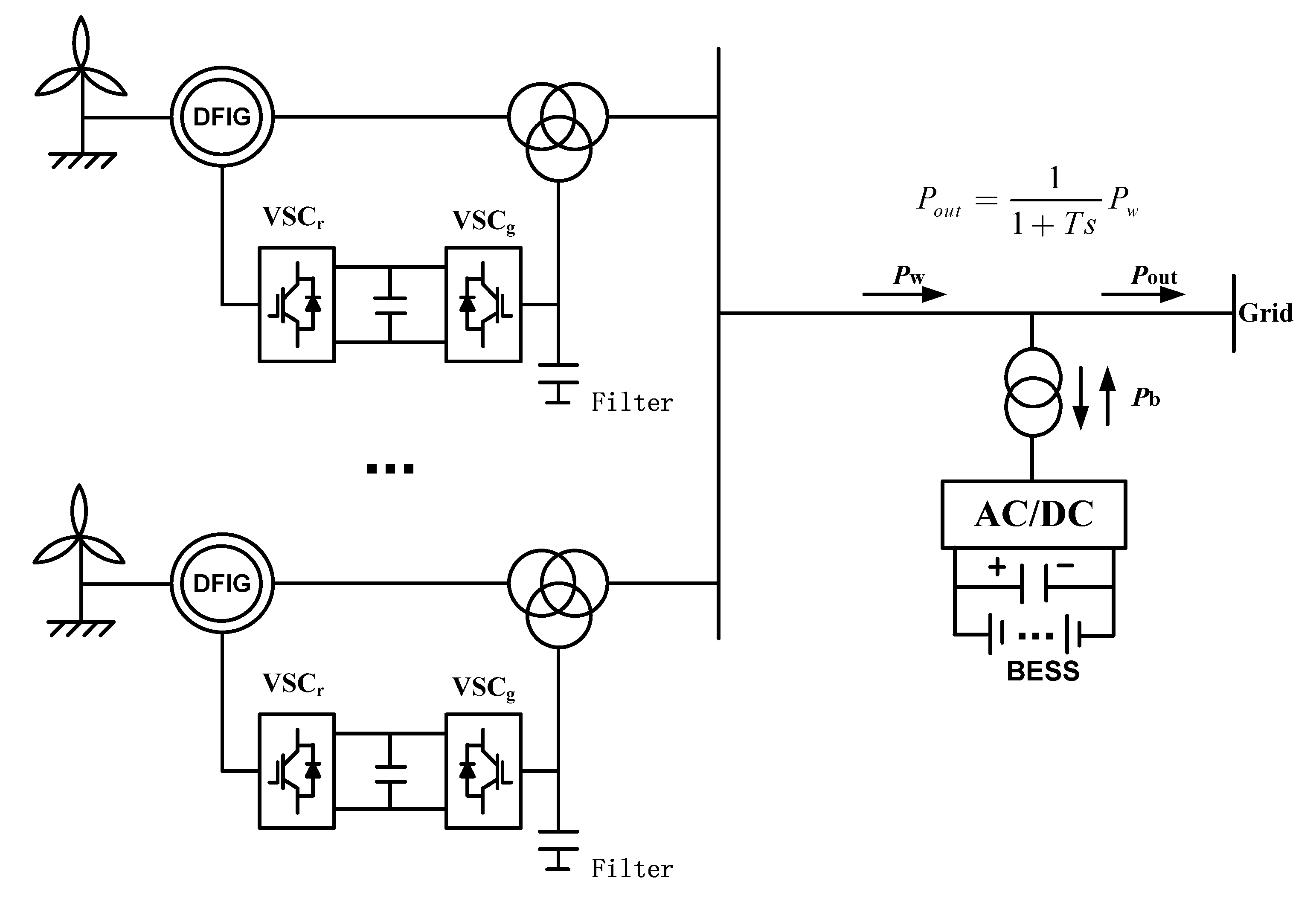
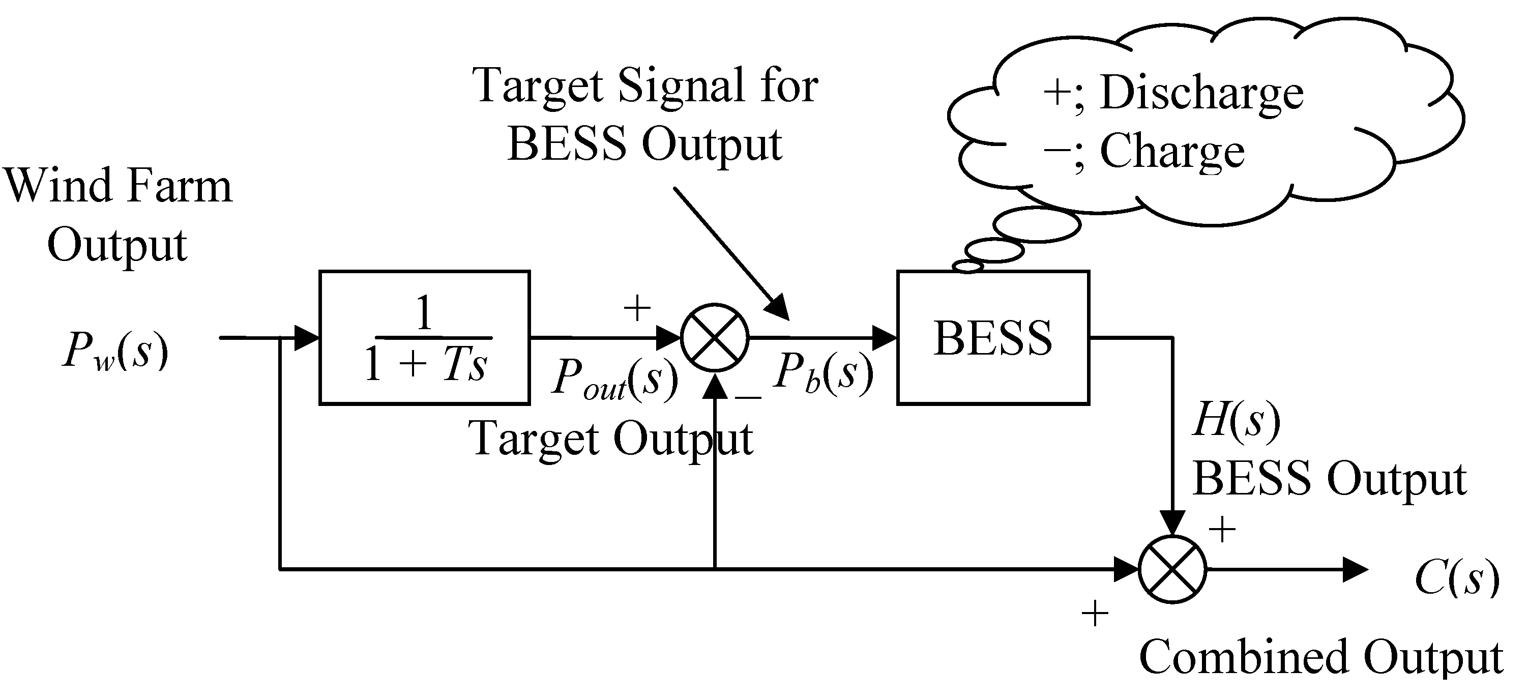
2.1. Simplified Diagrams of the Power Smoothing Control Model

The synthesis output of wind power and the energy storage system should be able to track the variation rule of the power load and overcome the larger fluctuations of relative load from wind power output and reverse adjustment characteristics. Moreover, the capacity of the energy storage system should be the minimum needed considering the economy while ensuring certain safety redundancy. In order to reduce the fluctuations of the active power from a wind farm, increasing the energy storage systems can be used to smooth the active power output from the wind farm. The generation system structure of wind power combined with an energy storage system is as shown in Figure 1.
Figure 1. The generation system structure of wind power combined with energy storage system.
Energies 05 01593 g001
In Figure 1, Pw is the active power of wind farm output; Pout is the grid-connected power; Pb is the target signal for BESS, T is the time constant of first-order low-pass filter, it adopts 0 s~1800 s. When Pout is higher than Pw, the surplus energy will be stored in BESS. When Pout is less than Pw, the energy stored in BESS will be released to supply it to the power grid. The fluctuations of the output power for wind farm can be effectively restrained in this way and the active power output of the wind farm gets more smoothing.
At present an Inertial Filter method is adopted to restrain the fluctuation of wind power in most documents and a simplified model of power smoothing combining wind power with an energy storage system given in [16] is shown in Figure 2.
Figure 2. The simplified diagrams of power smoothing control model.
Energies 05 01593 g002
where C(s) is the total output after being smoothed, H(s) is the output power of BESS.

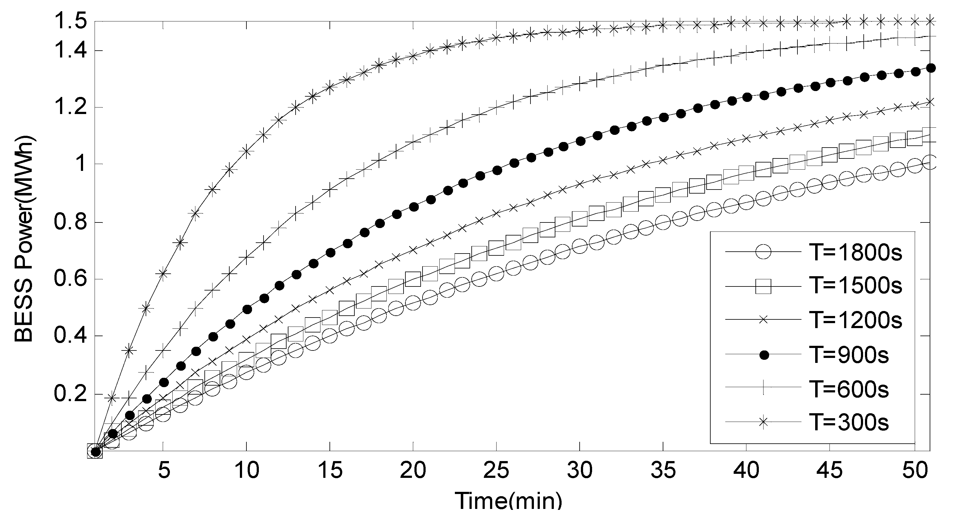
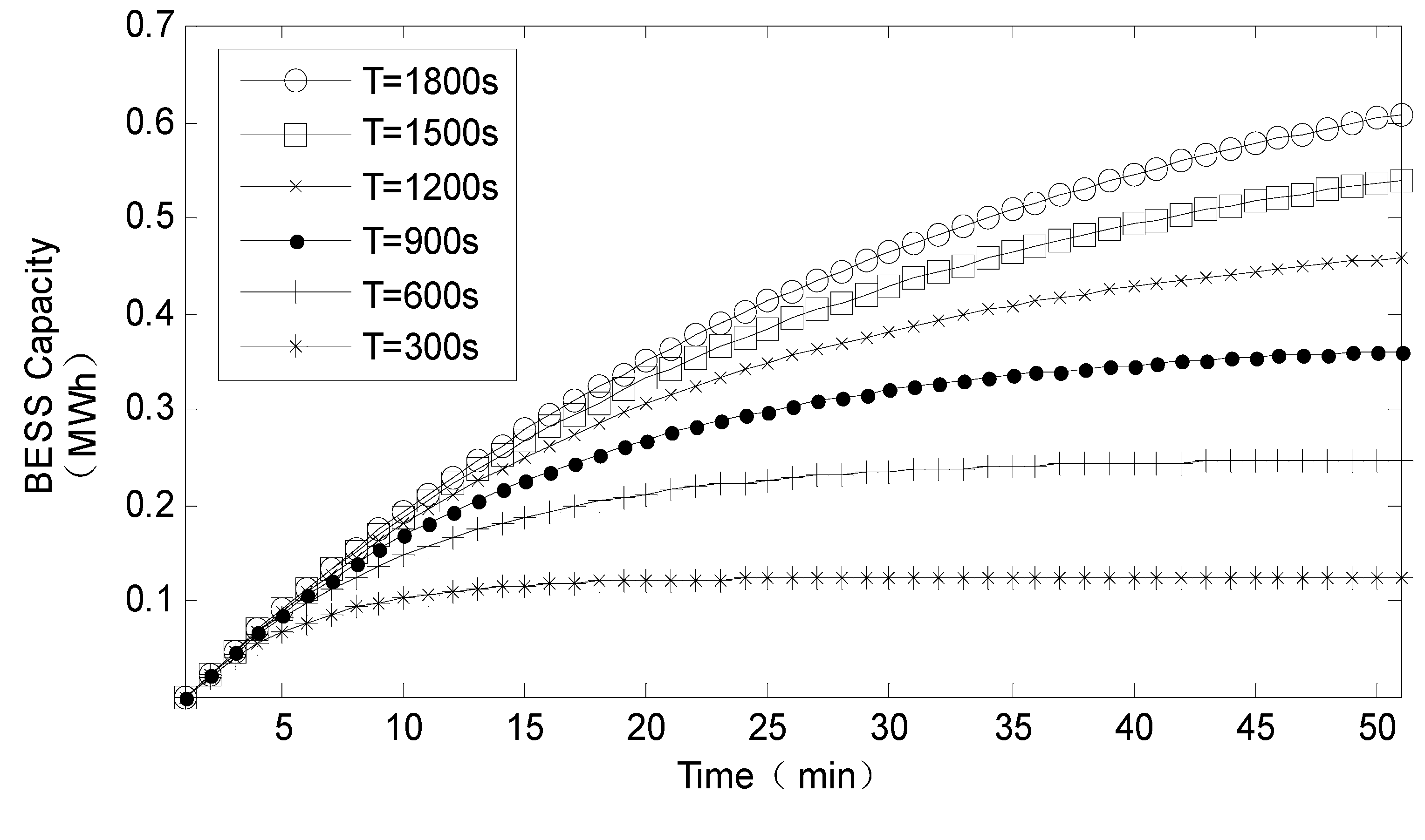
2.2. The Relationship between Inertia Filtering Time Constant and BESS Capacity

Usually Pout(s) is derived from Pw(s) after first-order low-pass filter according to Figure 2, that is:
P o u t ( s ) = 1 1 + T s P w ( s )
P b ( s ) = P o u t ( s ) P w ( s ) = T s P o u t ( s ) = T s 1 + T s P w ( s )
C ( s ) = H ( s ) + P w ( s )
Laplace Inverse Transformation and integral in time domain of Pb(s) is described by:
B ( T ) = T 0 T L 1 ( P b ( s ) ) d t = T 0 T L 1 ( T s 1 + T s P w ( s ) ) d t
where B(T) is the instantaneous capacity value of energy storage system at the moment T.
The calculation formula of power variation rate is described by:
ε = Δ P max   1 m P max
where ε is defined as the variation rate, Δ P 1 m is the power difference in the moment of t − 1 and t smoothed by Inertia Filtering in 1 min, Δ P max   1 m is the maximum of the power difference Δ P 1 m , P max is the total installed capacity.
When the active power of the wind generator Pw(s) is a step signal and equal to 1.5 MWh, Figure 3 shows the relationship of the output power of BESS and time constant T of the low-pass filter. It can be seen from it that time constant T is smaller, the speed of the grid-connected power tracking the active power from wind farm is faster.
Figure 3. The relationship between the output power of BESS and time constant T.
Energies 05 01593 g003
The capacity of BESS is calculated by (4), the relationship between the capacity of BESS and time constant T is shown in Figure 4.
Figure 4. The relationship between the capacity of BESS and time constant T.
Energies 05 01593 g004
It can be seen that if the required storage capacity of wind generator system increases, higher energy storage costs will be required. In order to reduce the cost of the energy storage system, the maximum storage capacity within a period of time needs to be allocated which can satisfy all requirements of the energy storage system. When T adopts the values of 600 s, 1200 s, 1800 s, respectively, the relationship of the allocated capacity of BESS calculated by (4) and the power variation Δ P 1 m with time constant T is shown in Figure 5.
Figure 5. The relationship of the allocated capacity and power variation of BESS with the time constant T.
Energies 05 01593 g005
Obviously, the greater the inertial time constant T is, the less the smoothed power variation is, the smoother the power curve is, but the required capacity configuration of BESS is bigger. When T is equal to 600 s, the power variation rate calculated by (5) is 7%, the allocated capacity of BESS is 14.4780 MWh; when T is 1200 s, the power variation rate is 3.17%, the allocated capacity of BESS is 28.1508 MWh; when T is 1800 s, the power variation rate is 2.07%, the allocated capacity of BESS is 41.6251 MWh. For some 99 MW wind farms, when T takes the value 1800 s, the probability of the variation rate every minute by less than 2% is 99.99%, which can meet the rules for access of wind power integration into the electricity system.

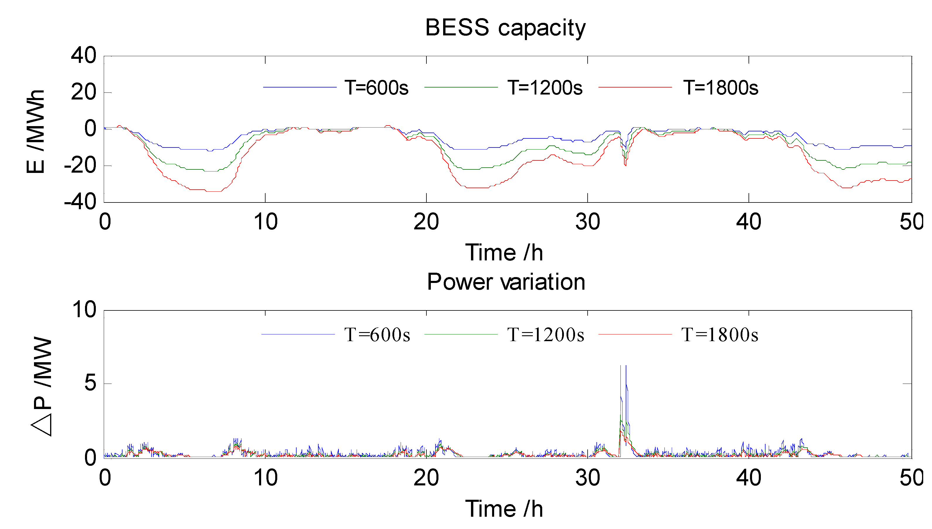
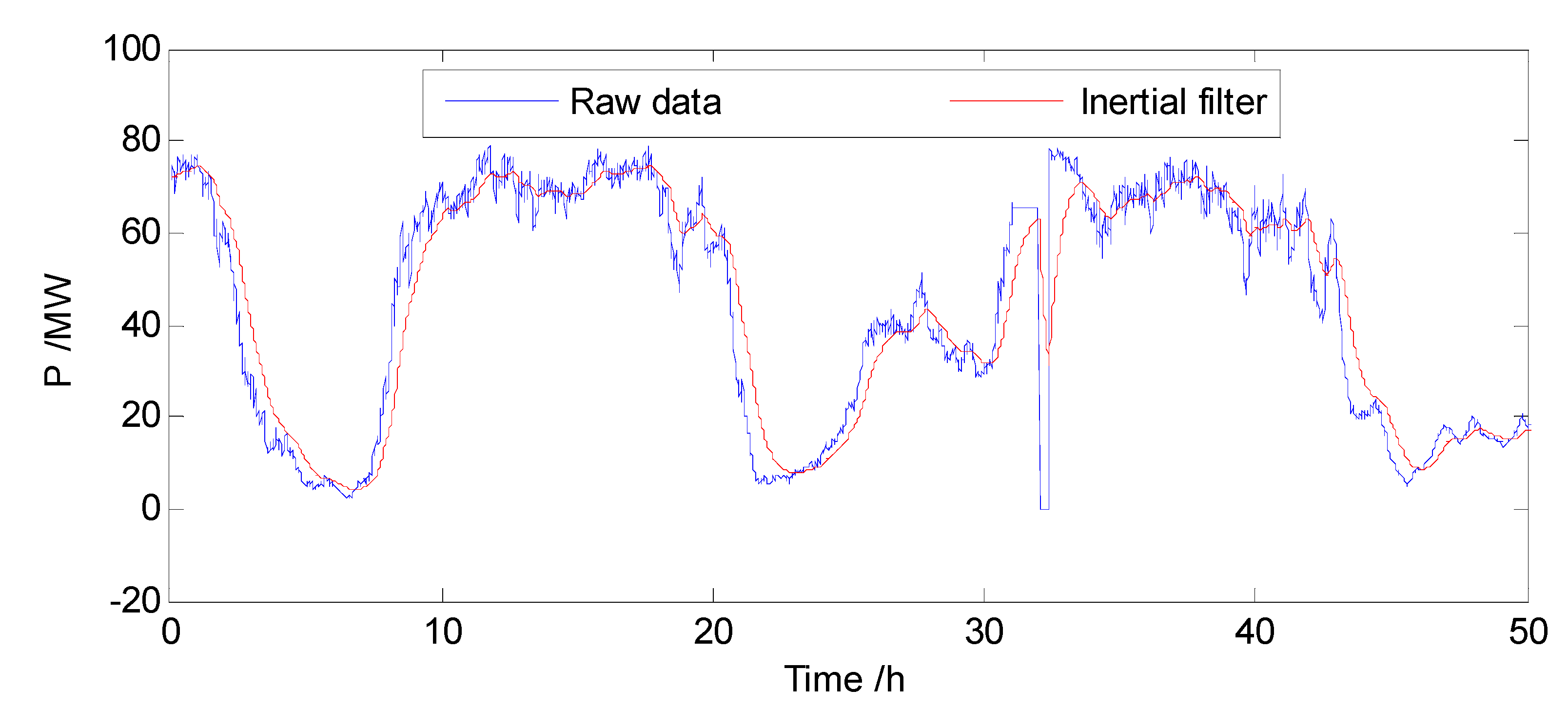
2.3. Simulation Example of Power Smoothing Based on an Inertial Filter

The historical active power operating data at a wind farm in 2010 is used to perform power smoothing by an Inertial Filter in MATLAB where T is 1800 s. The power curve smoothed by the Inertial Filter is shown as Figure 6, in which takes the power values of 50 h.
Figure 6. The smoothed power curve by Inertial Filter when T is 1800 s.
Energies 05 01593 g006
It can be seen from it that the curve smoothed by Inertial Filter is smoother than the actual wind power curve in some wind farms, but it lags behind the actual wind power.

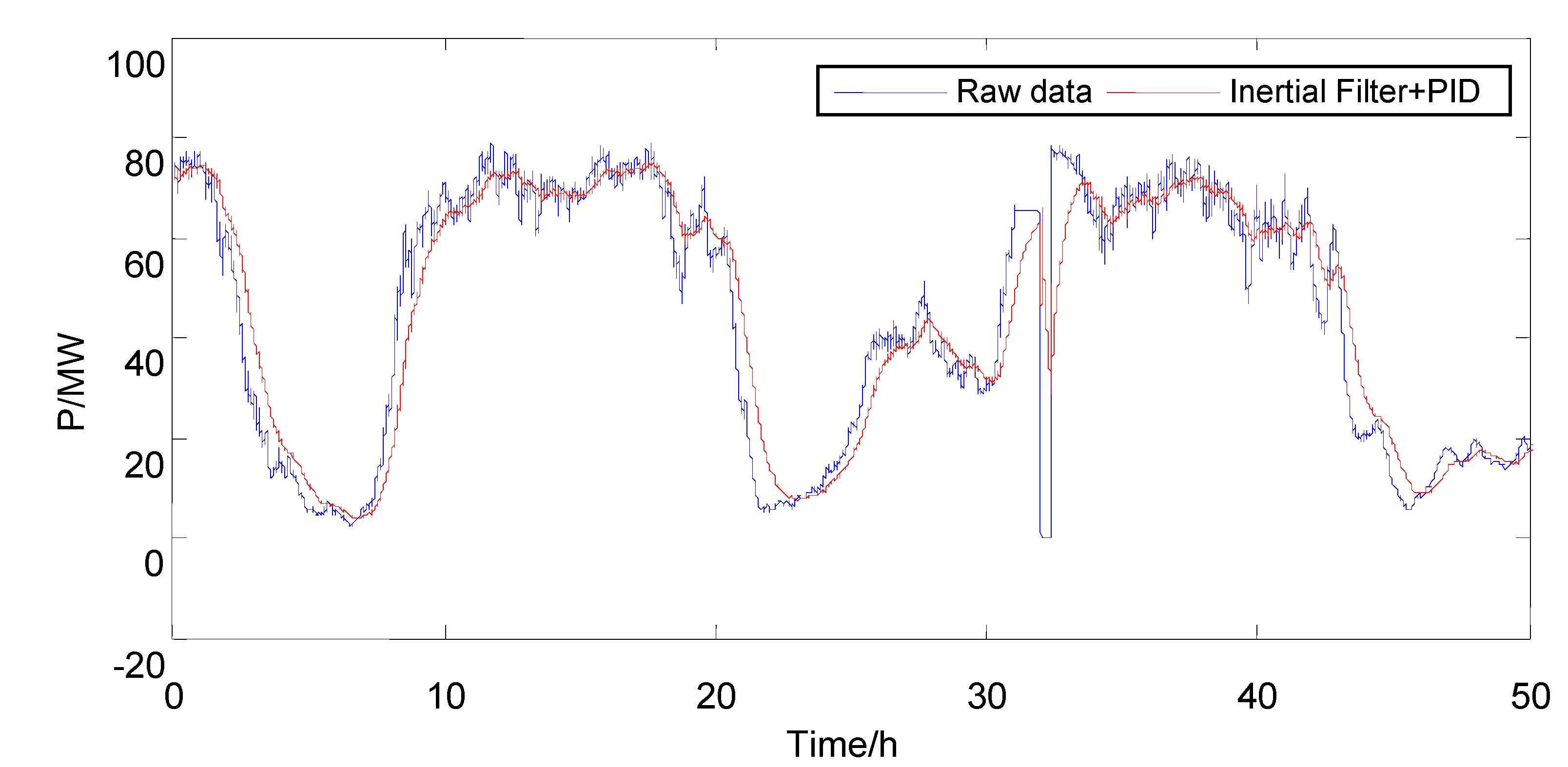
2.4. Power Smoothing Control Based on Inertial Filter and PID Control Algorithm

The purpose of power smoothing control is to ensure the active power is filtered into the power grid and the excess power is absorbed by BESS, and the lack of power is released by BESS. A bidirectional energy storage converter is the core of energy conversion in an energy storage system, AC rectified to DC is stored in an energy storage battery or DC inverted to AC is sent to the power grid by the AC to DC transformer, which usually works under constant pressure and constant current modes. At present the charging and discharging control of BESS is realized by a PID algorithm to control the current and the voltage. The present PID control action is determined by the deviation between the measured output value and the set value in the present and the past. The BESS model is regarded as a first-order inertia link in this paper. The power smoothing control curve combining an Inertial Filter with a PID algorithm is shown as Figure 7, where P is 5 and Ts is 0.1.
Figure 7. The curve of power smoothing control combining an Inertial Filter with a PID control algorithm.
Energies 05 01593 g007
Figure 6 shows that between target power Pb(s) and actual output power H(s) of the energy storage system there is a certain deviation which is related to the parameters of the PID control algorithm and the characteristics of the energy storage battery leading to the power C(s) of wind power into grid being obviously different from the expected power Pout(s), so the smoothness of the actual output power received by the PID is less than the expected output power compared with Figure 6. The lags caused by the Inertial Filter cannot be eliminated even using PID control in the control process, because the battery is charged and discharged frequently, the power control curve in Figure 6 is not very smooth and some burrs exist.

3. The Construction of a Power Smoothing Model Based on a Hybrid Energy Storage System

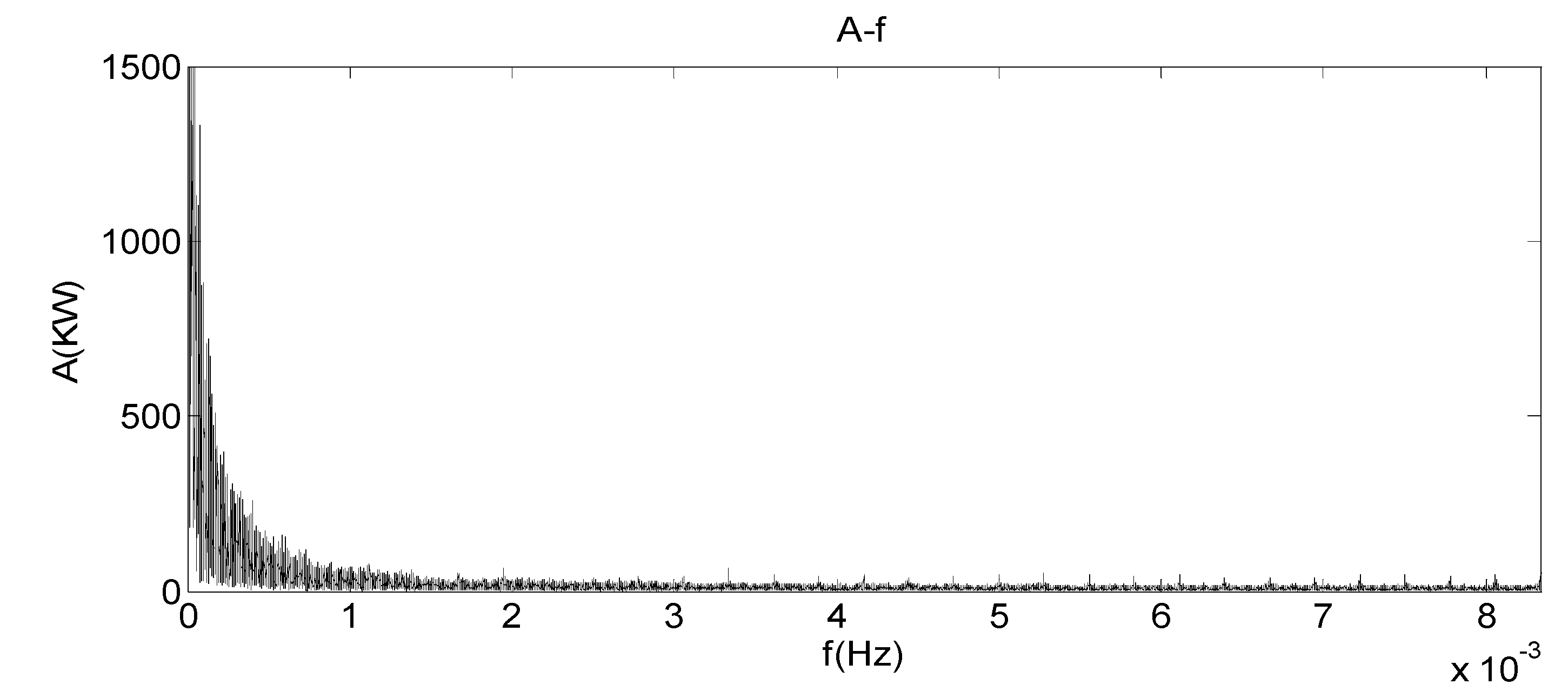
3.1. The Fluctuating Characteristics of Wind Power

The frequency response curve of wind power data collected from a 99 MW wind farm in April (sampling time takes 1 min) is shown in Figure 8.
Figure 8. The amplitude frequency characteristic of the output power from a wind farm.
Energies 05 01593 g008
It can be seen from it that power energy mainly concentrates in the low frequency part (0~10−4 Hz), the energy of the high frequency part is low and relatively average.

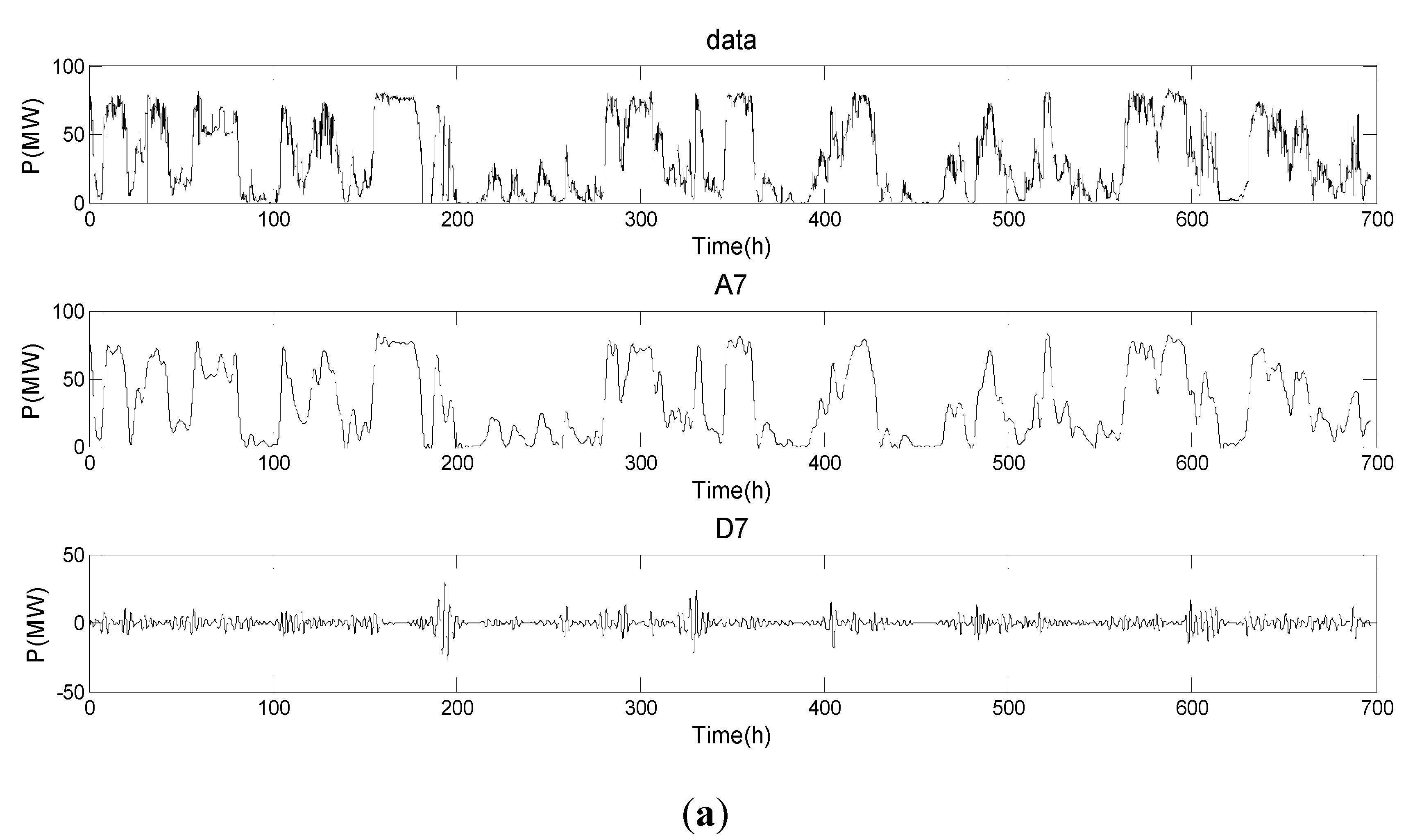
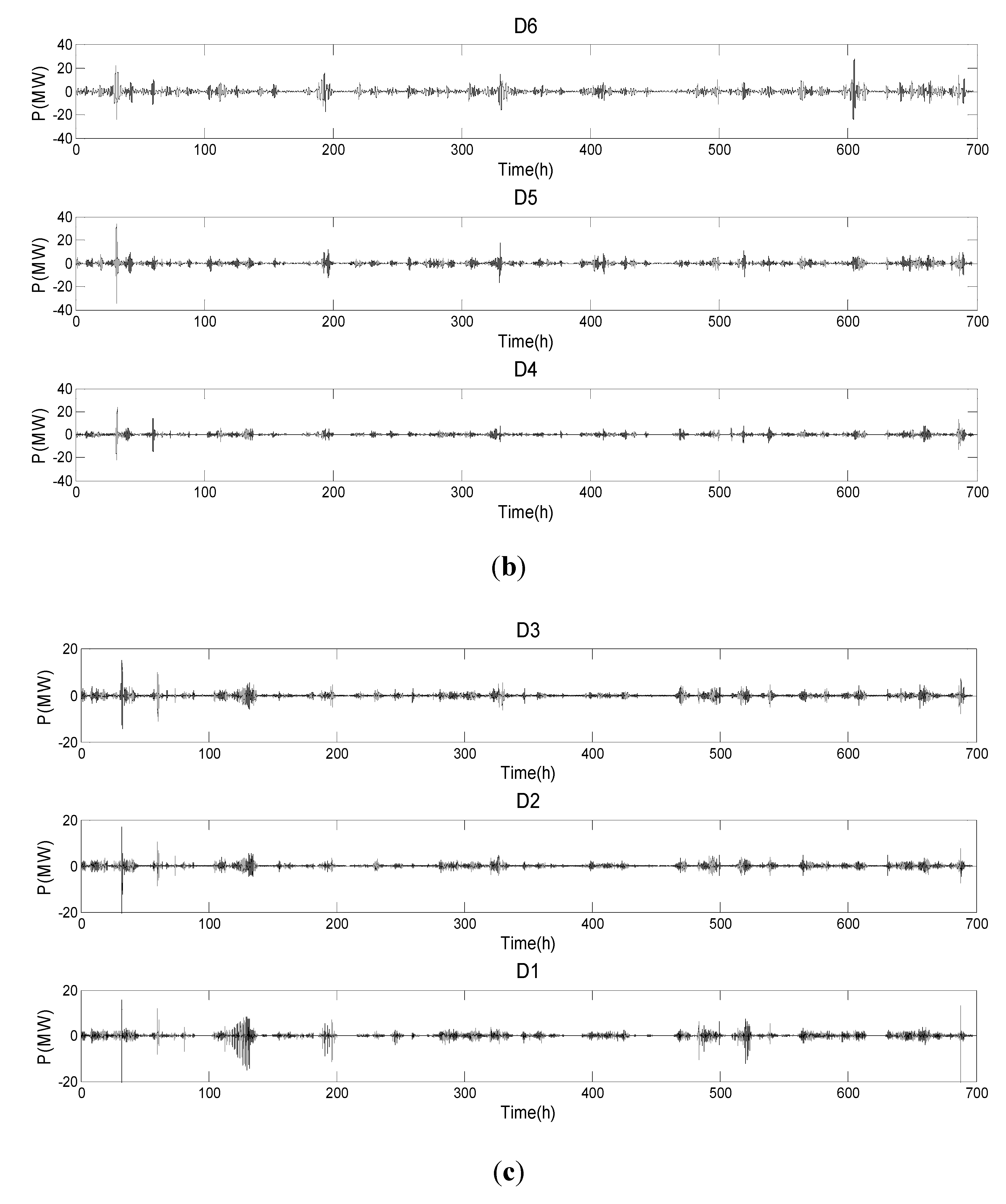
3.2. Multi-Scale Decomposition of Wind Power Signals Based on Multi-Resolution Analysis Theory

Multi-resolution analysis (MRA) or multi-scale approximation (MSA) is the design method of most practically relevant Discrete Wavelet Transforms (DWTs) and the justification for the algorithm of the Fast Wavelet Transform (FWT). For most of the signals S, the low frequency signal A1 gives the main features of the signal, while the high frequency signal D1 mainly refers to the interference and noise [19,21]. The tree structure of a three layers wavelet decomposition based on multi-resolution analysis is as shown in Figure 9.
Figure 9. The tree structure of a three layers wavelet decomposition based on multi-resolution Analysis.
Energies 05 01593 g009
We can use the breakdown:
S ( t ) = A 1 ( t ) + D 1 ( t ) = A 2 ( t ) + D 2 ( t ) + D 1 ( t ) = A 3 ( t ) + D 3 ( t ) + D 2 ( t ) + D 1 ( t )
where D i ( t ) is called the detail signals at level i and A i ( t ) is called the approximation signals at level i .
According to the above method, wind power signals can be decomposed into the high frequency (detail) signals and the low frequency (approximation) signal, the energy of the high frequency signals is low and changes quickly, while the energy of the low frequency signals is high and changes slowly, and thus plays a dominant role. The low frequency part is decomposed into seven layers (Level takes the value 7) by a DB9 wavelet in this paper and its related power curve is shown in Figure 10 (f is equal to 1.3 × 10⁻⁴ Hz, calculated by 1/(60 × 27)).
In (a), the low frequency A7 constitutes the main part of the original power curve, in (b) and (c), high frequency part has less energy and fluctuates up and down near zero. In terms of this the energy of high frequency part can be absorbed which not only may smooth the power curve, but also reduce the capacity configuration of the required energy storage battery system and reduce the cost of the energy storage system.
Figure 10. The power curves of wavelet multi-scale decomposition. (a) The power curves of low frequency A7 and high frequency D7; (b) the power curves from high frequency D4 to D6; (c) the power curve from high frequency D1 to D3.
Energies 05 01593 g010aEnergies 05 01593 g010b

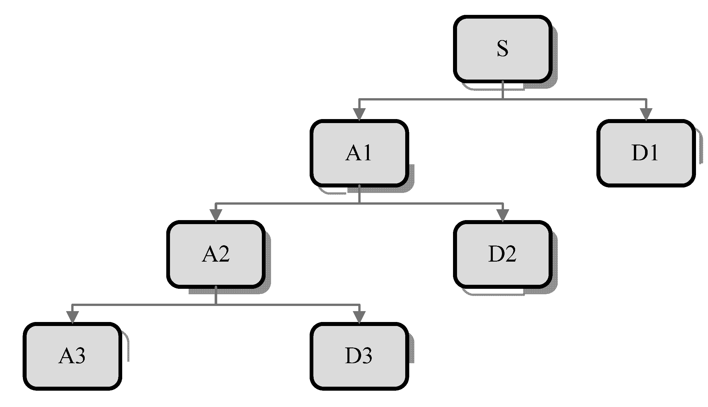
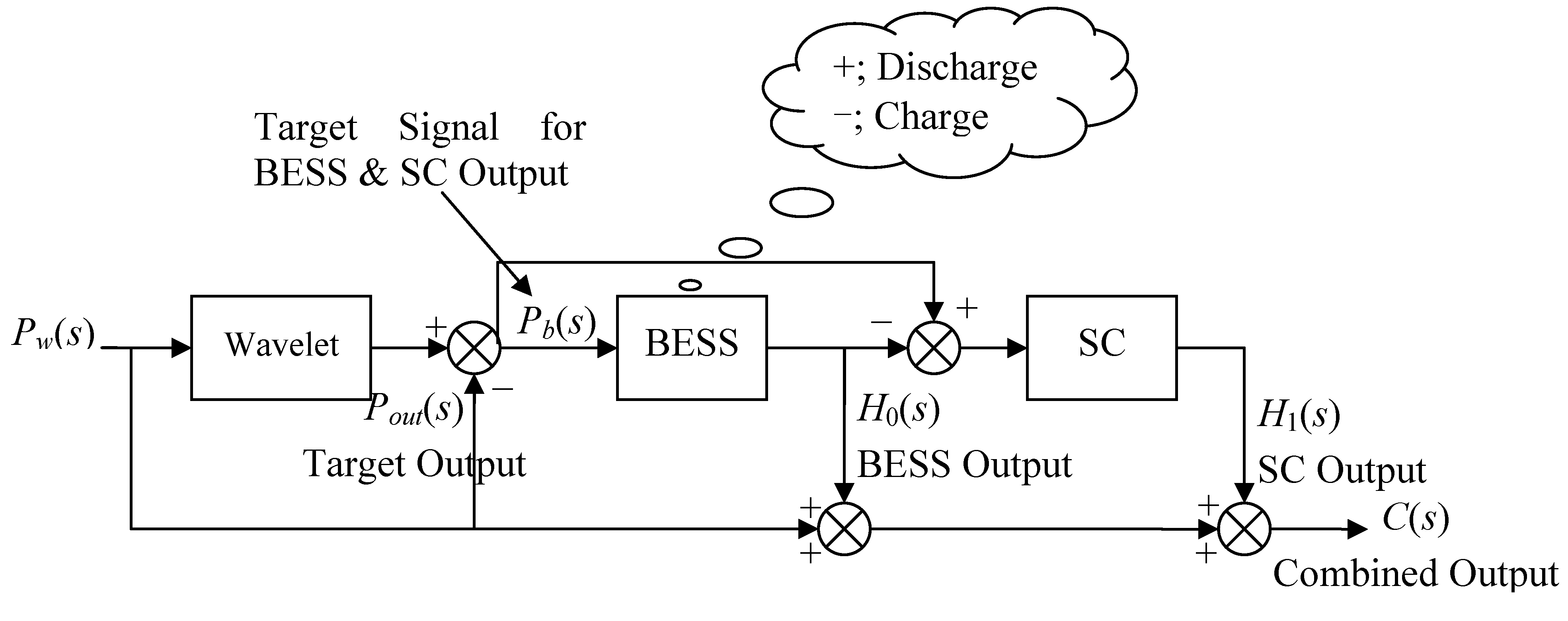
3.3. The Structure of the Power Smoothing Model Based on Hybrid Energy Storage Technology

According to a mechanistic analysis of energy storage, the energy storage density of BESS is high, power density and circulation service life are low [11,12]. Power density and circle life of SC are high, but the energy density is low [13,14], so high frequency power signal from D4 to D7 after wavelet decomposition is absorbed by BESS with the characteristics of higher capacity and slower response speed, the remainder and the high frequency power part from D1 to D3 are sent to super capacitors with its characteristics of smaller capacity and faster response speed to quickly carry out the filtering process. The structure diagrams of a hybrid energy storage system based on BESS and SC is shown in Figure 11.
Figure 11. The structure diagram of a hybrid energy storage system with BESS and SC.
Energies 05 01593 g011
Taking comprehensive advantage of BESS and SC in a hybrid energy storage system can quickly respond to the power smoothing instructions and better complete power smoothing tasks. Compared with a single energy storage system, the proposed hybrid energy storage system can achieve good smoothing effects for power fluctuations with high frequency and low energy or low frequency and high energy.

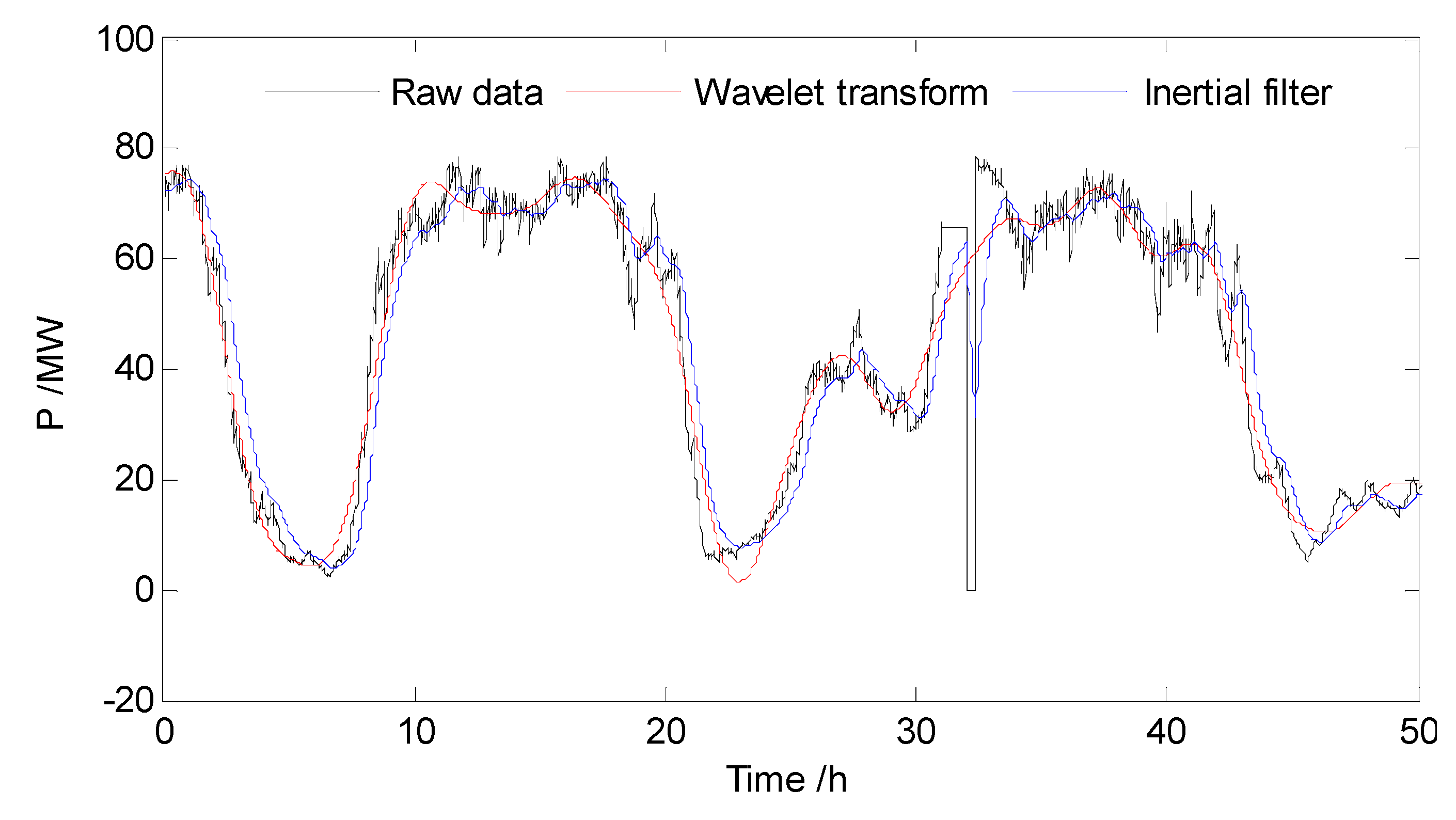
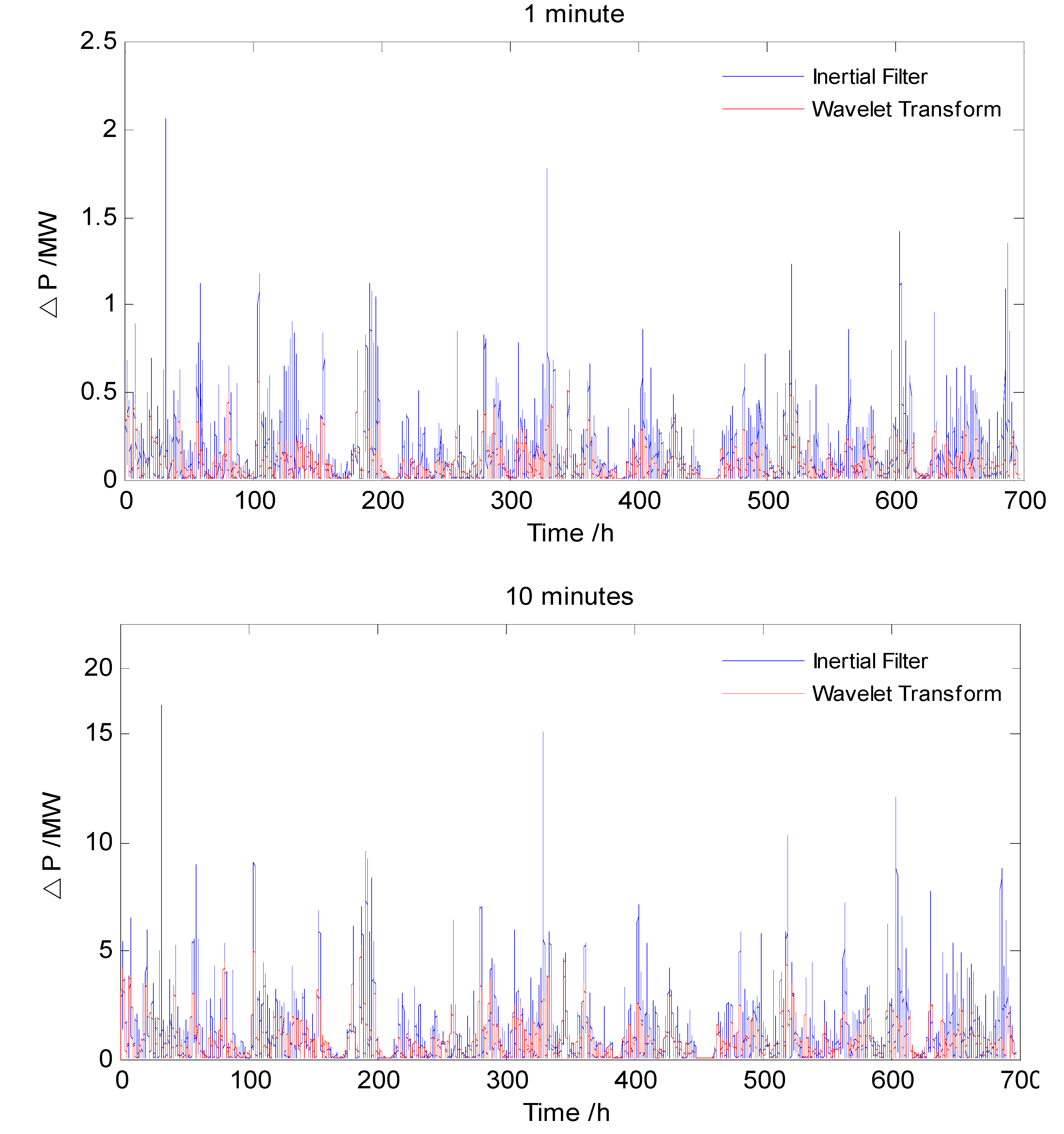
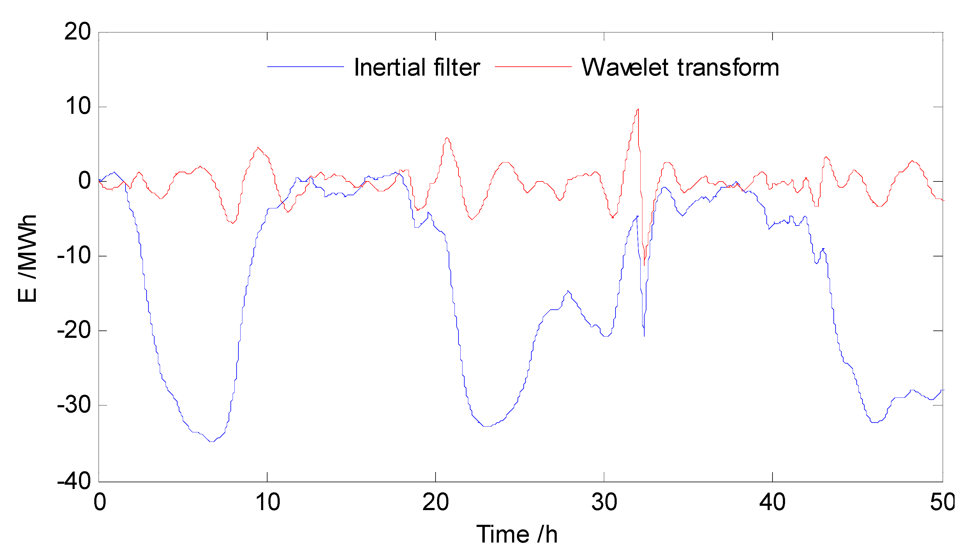
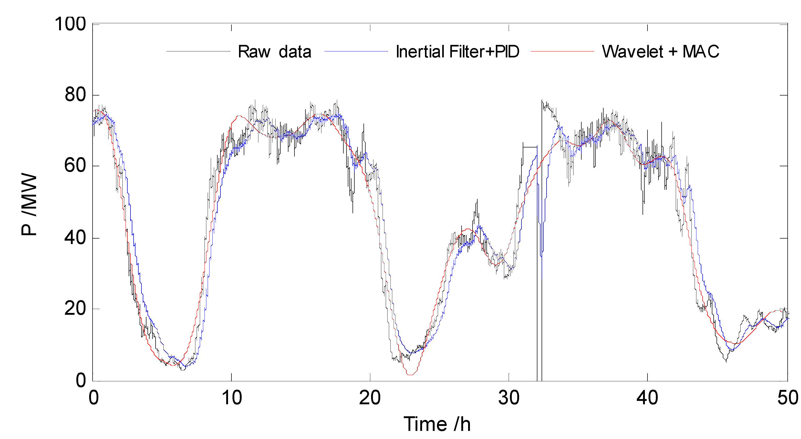
3.4. Comparison of Smoothed Power Based on Wavelet Theory and Inertial Filter

The installed capacity in some wind farms is 99 MWh, the maximum time constant T of the Inertial Filter takes the value 1800 s. The power curves for 700 h in April smoothed by an Inertial Filter and Wavelet Decomposition are contrasted and the smoothed power values for 50 h are given in Figure 12 for easy observation.
Figure 12. The comparison of power smoothing curve based on Inertia Filtering and Wavelet Transform in some wind farm about 50 h.
Energies 05 01593 g012
The smoothed power values after Wavelet Decomposition can track the actual wind power well and there are no lags, so the smoothing effect is obviously superior to that of the Inertial Filter. According to the technical regulation of wind farms connected to the electricity grid in China, for a 99 MW wind farm, the allowed maximum change amount in 1 min is equal to 20 MW; the allowed maximum change amount in 10 min is equal to 66.7 MW. The power variation is calculated by the power difference in the moment of t − 1 and t smoothed by the Inertial Filter and Wavelet Transform in 1 min and 10 min, respectively, shown in Figure 13.
Figure 13. The power variation smoothed by the Inertial Filter and Wavelet Transform in 1 min and 10 min.
Energies 05 01593 g013
Figure 13 shows that the maximum power variation in 1 min or 10 min yielded by the Inertial Filter and Wavelet Decomposition, respectively, is far less than the regulated requirement (5%) of the state grid company. The maximum power variation rate yielded by the Wavelet Transform in 10 min is 0.58% and the one yielded by the Inertia Filter in 10 min is 2.07%, so the power curves obtained by Wavelet Decomposition are smoother than the ones obtained with the Inertia Filter.

4. The Realization of Power Smoothing Control Strategy Based on Model Algorithmic Control (MAC)

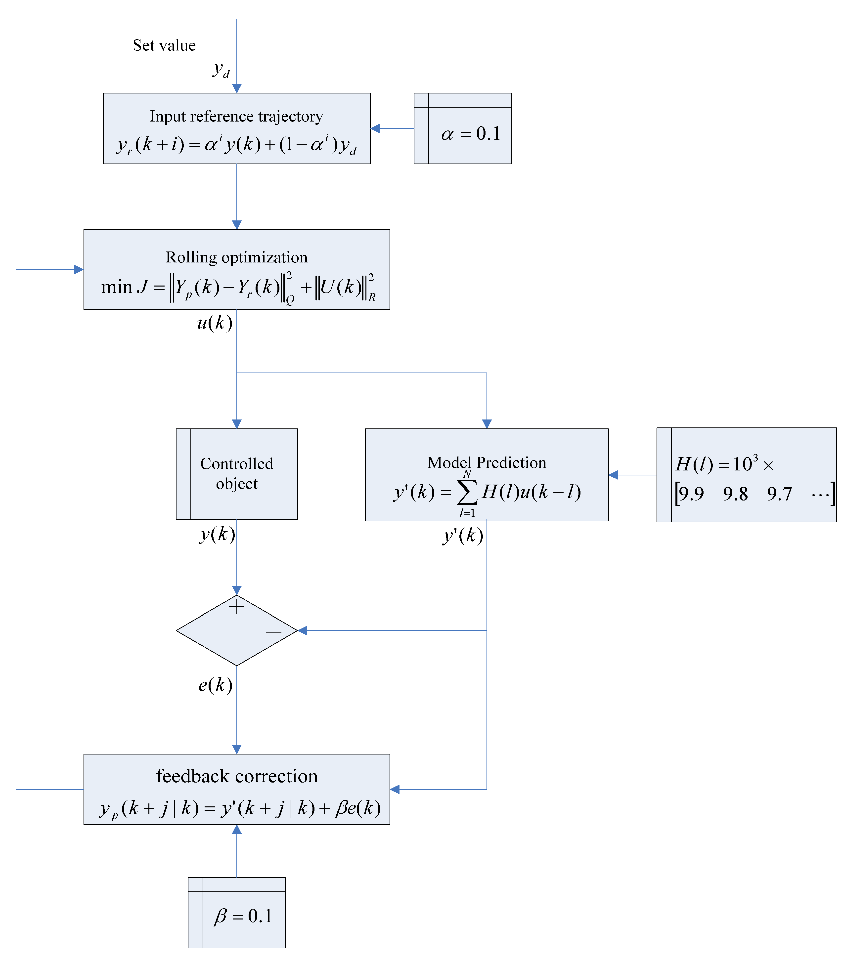
4.1. Principles of Model Algorithmic Control (MAC)

MAC is also called Model Predictive Heuristic Control (MPHC). It mainly includes internal model establishment, rolling optimization and feedback correction. A nonparametric model based on pulse response is regarded as the internal model to predict the output state of the future system with the past and the future of input/output state in term of the internal model, which is compared with a reference trajectory after finishing feedback correction using model output error.
Figure 14. The flow chart of MAC algorithm.
Energies 05 01593 g014
The behavior of a closed loop system is prescribed by the reference trajectory and it controls the aggressiveness of the algorithm. If the reference trajectory is much faster than the process then MPHC will not be efficient. The quadratic performance index is used to rolling optimization and controls to the system are calculated in current time in order to complete the entire cycle action [22,23,24]. The flow of the MAC algorithm shown in Figure 14 includes reference input, rolling optimization, predicting model and close loop prediction, where β is the feedback correction coefficient; if it is too big, the system will be shocked; otherwise, the fixed speed is so slow that it will have big errors. α is a constant more than zero by adjusting the reference trajectory to track the target value quickly.

4.2. Simulation Examples of Power Smoothing Control Strategy Combining MAC Control and Wavelet Transform

Predictive control can provide an early action control system which not only uses the current and past deviation values, but also uses predictive models to estimate the future deviation values in the process, and the optimal input strategy is determined by rolling optimization, however, the control input of PID is determined by the deviation between the current and past measured output values and the set value. In essence, it is superior to the PID algorithm. In order to illustrate the superiority of the method proposed in this paper further, the power smoothing control is realized by traditional PID control and MAC control, respectively, as shown in Figure 15.
Figure 15. The power control curves of a hybrid energy storage system based on PID control and MAC control in the period of 300 s.
Energies 05 01593 g015
In Figure 15, the active power from a wind farm may be regarded as a square wave, the sampling time of which takes 60 s. When PID control is used to track the target power Pb(s), if the integral time is too big, it will cause overshoot; if the integral time is too small, it needs longer time to become stable. It can be seen that MAC control method can track the target power quicker than the PID control method to ensure the computational speed in a practical application for the real-time processing requirements. Due to the influence of the inertia and the response speed of BESS, its actual output is not completely equal to the target value which mainly reflects in the high-frequency part, SC is used to compensate the difference part and makes the output of battery and SC closer to the target value in the end. The mean error between the combined output power C(s) and the target power Pb(s) obtained by PID control and MAC is equal to 134.4 kW and 28.35 kW, respectively. In order to further compare, the use of the combination of Inertial Filtering and PID as well as the combination of Wavelet Transform and MAC to achieve power smoothing control, the contrast curve is as shown in Figure 16.
Figure 16. The power smoothing control curves combining Inertial Filtering with PID and combining Wavelet Transform with MAC.
Energies 05 01593 g016
In Figure 16, the effect of power smoothing control based on hybrid energy storage combining Wavelet Filter with MAC is better than the one yielded by combining Inertial Filtering and PID. Because it not only considers the fluctuations of the low-frequency part (main portion of the wind power) but also the fluctuations of the high-frequency part, the power difference obtained by the Wavelet Transform is regarded as the target value of BESS after the output power curve from wind farm is smoothed by the Wavelet Transform, the charging and discharging control for BESS is quickly completed by MAC as shown in Figure 15. On the other hand, the grid-connected power Pout(s) filtered by Wavelet Transform does not have the lags caused by the Inertial Filter which has been proven in Section 2. The control effect of MAC on the target power filtered by Wavelet Transform is so ideal that the maximum error is only about 10 kWh, so it has no difference from Figure 11 without any burrs after MAC control.

5. The Capacity Allocations of BESS Based on Wavelet Transform

In the process of wind power rising or falling, BESS will be in charge and discharge mode for a long time so that the desired capacity configuration of BESS is larger due to the lags of the Inertia Filter algorithm. The high frequency part of wind power is filtered by the Wavelet Filter algorithm, which has the advantages of short period and low energy, so BESS is in a rapid charging and discharging mode, and the desired capacity configuration of BESS is smaller. The calculation formula of the desired capacity configuration by Wavelet Transform is as follows:
E = max 0 t Δ p ( t ) d t
where Δ p ( t ) is the power difference between the output power Pw(s) from wind farm and grid-connected power Pout(s) in 1 min, shown in Figure 11.
The high frequency part from D4 to D7 of the input power decomposed by the Wavelet Transform is absorbed by BESS to realize power smoothing control. The capacity allocations of BESS respectively given by the above two kinds of power smoothing methods, Inertial Filter time constant T is equal to 1800 s, the level of wavelet scales is equal to 7, which is realized by MATLAB to analyze the power data from April and the whole year under different times in a 99 MW wind farm. The comparison of energy storage capacity based on Inertial Filtering and Wavelet Transform is shown in Figure 17 in a wind farm over 50 h.
Figure 17. The comparison of energy storage capacity in a wind farm over 50 h based on Inertial Filtering and Wavelet Transform, respectively.
Energies 05 01593 g017
The storage capacity configuration of the BESS-based Inertia Filtering method calculated by (5) is equal to 40.58 MWh in 50 h; the storage capacity configuration of the BESS-based Wavelet Transform calculated by (6) is equal to 21.02 MWh. Because the power curve smoothed by the Inertia Filter has larger lags and obviously deviates from the actual power curve, as shown in Figure 5, it will take a relatively long time to get back to the initial state of battery. The power curve smoothed by the Wavelet Transform passes through the actual power curve as shown in Figure 12. It is very easy to quickly return to the initial state of battery by quickly switching between charging and discharging of BESS. Thus the required allocations of battery capacity obtained by the Wavelet Transform are smaller than the ones obtained by the Inertia Filter, the cost of BESS can be decreased rapidly so that BESS technology can be applied to better integrate wind power into the electricity system. In addition, the method of Inertia Filtering with a fixed time constant requires a larger time constant T which will cause excessive adjustment for smaller power fluctuations and increase the burden of BESS. However, the power data appears as zero between 30 h and 35 h which results in storage capacity increasing in that range. In practice, the capacity of BESS after removing power values with zero can be reduced rapidly. The allocation results are shown in Table 1 and Table 2.
Table 1. The battery capacity allocations used for a wind farm in April (MWh).
TimeInertial FilterWavelet Filter
T = 600 sT = 1200 sT = 1800 s
CapacityFluctuation rateCapacityFluctuation rateCapacityFluctuation rateCapacityFluctuation rate
10 min0.11750.22%0.13240.12%0.13810.08%0.36050.05%
30 min0.44020.36%0.56190.18%0.62580.13%0.340.05%
1 h0.57510.36%0.90730.18%1.14060.13%1.24060.16%
6 h12.35311.07%23.69100.8%34.70480.68%4.25650.47%
12 h12.77341.36%24.40471.05%35.85690.89%10.41470.47%
24 h12.77341.36%24.40471.05%35.85690.89%11.55060.47%
7 day12.08906.27%27.34573.17%40.57772.07%21.02060.57%
14 day14.08916.27%27.34833.17%40.59022.07%35.26890.58%
30 day14.47806.27%28.15083.17%41.62512.07%35.26890.58%
Table 2. The battery capacity allocations used for a wind farm every month (MWh).
MonthInertial FilterWavelet Filter
T = 600 sT = 1200 sT = 1800 s
CapacityFluctuation rateCapacityFluctuation rateCapacityFluctuation rateCapacityFluctuation rate
113.55255.69%26.36053.07%39.24662.11%32.03430.68%
212.04084.91%23.38652.78%34.93131.93%25.98370.58%
311.53356.01%22.46093.07%33.36632.04%26.94490.57%
414.47806.27%28.15083.17%41.62512.07%35.26890.58%
514.41557.02%28.11013.74%41.81262.55%41.92050.75%
613.40533.12%25.93781.71%38.38041.28%26.32180.48%
713.43975.29%25.96932.53%38.29021.81%26.80480.46%
811.788813.22%22.41041.57%32.36371.19%19.66210.39%
914.04772.98%27.20931.66%40.06761.21%23.48340.54%
1014.63363.61%28.33312.20%41.78071.56%26.68680.54%
1115.25215.63%29.49353.12%43.73272.14%29.01390.75%
1215.06426.47%29.33453.36%43.56192.29%38.08490.79%

6. Conclusions

According to the amplitude frequency characteristics of wind power, a power smoothing control strategy based on a hybrid energy storage system is proposed in this paper. Wind energy signals are decomposed into the high frequency signals from D1 to D7 and the low frequency signal A7 by wavelet decomposition theory. The low frequency signal A7 after wavelet decomposition is regarded as the desired connected-grid power value, and the high frequency signals from D1 to D7 are respectively rapidly absorbed by SC and battery. Compared with the traditional Inertial Filtering method, the fluctuation rate of wind power smoothed by the Wavelet Transform is less than the one smoothed by Inertia Filtering, that is, the smoothing extent of the Wavelet Transform is greater than that of the Inertial Filter. At the same time the use of the Wavelet Transform can overcome the time lags caused by the Inertia Filter method. The charging and discharging control of the battery are realized by PID control and MAC control. The corresponding capacity design is given under the premise of meeting wind power standards according to the characteristics of the low frequency signal decomposed by the Wavelet Transform to reduce the size of the energy storage devices as far as possible, which has a certain practical value.

Acknowledgments

This paper is supported by the National Natural Youth Science Fund Project (51107126).

References

  1. Sun, T.; Wang, W.S.; Dai, H.Z. Voltage fluctuation and flicker caused by wind power generation. Power Syst. Technol. 2003, 27, 62–66. [Google Scholar]
  2. Chi, Y.N.; Wang, W.S.; Dai, H.Z. The Study of Grid Wind Farms Transient Voltage Stability Based on Doubly-Fed Induction Generator. J. Chin. Electr. Eng. 2007, 27, 25–31. [Google Scholar]
  3. Chi, Y.N.; Wang, W.S.; Liu, Y.H. Impact of large scale wind farm integration on power system transient stability. Autom. Electr. Power Syst. 2006, 30, 10–14. [Google Scholar]
  4. Bialasiewicz, J.T.; Muljadi, E. The Wind Farm Aggregation Impact on Power Quality. In Proceedings of the 32nd Annual Conference of IEEE Industrial Electronics, Paris, France, 2006; pp. 4195–4200.
  5. Li, X.; Hu, C.S.; Liu, C.J.; Xu, D.H. Modeling and Control of SCES based on Wind Farms Power Regulation System. Autom. Electr. Power Syst. 2009, 9, 86–90. [Google Scholar]
  6. Paatero, J.V.; Lund, P.D. Effect of energy storage on variations in wind power. Wind Energy 2005, 8, 421–441. [Google Scholar] [CrossRef]
  7. Li, Q.; Yuan, Y.; Tan, D.Z. Application progress of Energy storage technology in wind power grid. J. He Hai Univ. 2010, 38, 115–112. [Google Scholar]
  8. Pan, W.X.; Fan, Y.W.; Ju, L.; Gao, A.L. Optimal selection of pumped storage system capacity in Wind farms. Electr. Technol. 2008, 3, 120–124. [Google Scholar]
  9. Tan, J.; Li, G.J.; Tang, Z.W. Power control and benefit analysis based on compressed air energy storage in wind farms. Autom. Electr. Power Syst. 2011, 8, 33–37. [Google Scholar]
  10. Ruan, J.P.; Zhang, J.C.; Wang, J.H. Study of flywheel storage system to improve the stability of grid wind farms. Power Sci. Eng. 2008, 3, 5–8. [Google Scholar]
  11. Tomkoi, A.; Takahashi, R.; Murata, T. Smoothing control of wind power generator output by superconducting magnetic energy storage system. In Proceedings of International Conference on Electrical Machines and Systems, Seoul, Korea, October 2007; pp. 302–307.
  12. Jia, H.X.; Zhang, Y.; Wang, Y.F. Application of Energy storage technology in wind power systems. Renew. Energy 2009, 27, 10–15. [Google Scholar]
  13. Price, A. Technologies for energy storage-present and future: Flow batteries. In Proceedings of Power Engineering Society Summer Meeting, Washington, DC, USA, July 2000; pp. 1541–1545.
  14. Suvire, G.O.; Mercado, P.E.; Ontiveros, L.J. Comparative Analysis of Energy Storage Technologies to Compensate Wind Power Short-Term Fluctuations. In Proceedings of IEEE PES Power Systems Conference and Exposition, Sao Paulo, Brazil, November 2010; pp. 522–528.
  15. Yoshimoto, K.; Nanahara, T.; Koshimizu, G. New control method for regulating state-of-charge of a battery in hybrid wind power/battery energy storage system. In Proceedings of the 2006 IEEE PES Power Systems Conference and Exposition (PSCE '06), Atlanta, GA, USA, November 2006; pp. 1244–1251.
  16. Sercan, T.; Mesut, E.B.; Subhashish, B.; Alex, H. Validation of battery energy storage control for wind farm dispatching. In Proceedings of the 2010 IEEE Power and Energy Society General Meeting, Minneapolis, MN, USA, July 2010; pp. 1–7.
  17. Liu, J.T.; Zhang, J.C. Control method of energy storage system combining super capacitor with battery. Power Sci. Eng. 2011, 1, 1–4. [Google Scholar]
  18. Yu, P.; Zhou, W.; Sun, H.; Guo, L.; Sun, F.S.; Sui, Y.Z. Hybrid energy storage system and its control system design for smoothing wind power. Chin. Electr. Eng. 2011, 31, 127–133. [Google Scholar]
  19. Zhou, Y.; Cheng, J. The Wavelet Transform and its application. Physics 2008, 37(1), 24–32. [Google Scholar]
  20. Han, X.; Cao, H.; Li, Y.; Xiao, Y.; Tang, X. Short-time wind speed prediction based on wavelet and LS-SVM. Acta Energiae Solaris Sinica 2011, 32(17), 1538–1542. [Google Scholar]
  21. Wang, L.; Dong, L.; Liao, X.; Gao, Y. Short-term power prediction of a wind farm based on wavelet analysis. Proc. CSEE 2009, 29(28), 30–33. [Google Scholar]
  22. Qian, J.; Zhao, J.; Xu, Z. Prediction Control; Chemical Industry Press: Beijing, China, 2007. [Google Scholar]
  23. Xing, L.; Datta, A. Adaptive model algorithmic control. Am. Control Conf. 2001, 6, 4155–4160. [Google Scholar]
  24. Oh, T.K.; Mao, Z.Z. Improved model algorithmic control scheme for thyristor-controlled series capacitor. In Proceedings of the Power Engineering Society Summer Meeting, Vancouver, Canada, July 2001; pp. 1560–1565.

