1. Introduction
Smart Grid power systems require highly efficient and reliable energy generation, distribution, and consumption. Highly developed information and communications technology (ICT) is utilized to improve the control and optimization of the performance of power distribution systems.
To increase energy generation, various dispersed power sources such as photovoltaic, wind power and fuel cells are incorporated in power supply systems. These dispersed power sources are not always guaranteed to generate high-quality power. For example, the generation rate of photovoltaic generating power is weather dependent. Usually, DC power from the dispersed sources is inverted to AC power, whose quality might be lower than the commercial power generated at power station, to be delivered through the commercial power network. Conversely, some loads do not necessarily require high-quality power. For example, charging batteries does not require high-quality power. Hence, the balance between the loads and the generated powers in the system is one of the important factors for effective power consumption.
To realize these needs, power packetization and its routing have been proposed for use as in-home power transfer systems [
1,
2,
3,
4]. In communication networks, the packet delivers information. A
power packet delivers electric power together with an information tag superimposed on its voltage waveform in the power network. It enables us to deliver the power to the destination load while balancing the power quality with the load demand. The concept of power packetization in a power distribution line was proposed in [
5]. In the Cloud Computing context, energy dispatched as a pulse, called an energy packet, is also proposed as means to provide energy on demand to Cloud Computing servers [
6], in a manner similar to power packetization. In [
5,
6], to attach the information tag to the electric power, the information transmission lines were set up separately from the power distribution lines, or the methods were not mentioned explicitly. In the system proposed in this study, the power packet [
1,
2,
3,
4] consists of the power payload and the information tags,
i.e., the information tags are physically added to the electric power. The payload is the power supplied by the selected power sources. The distribution control of the power packet flow is realized by reading the information tag contained in the power packets.
In this study, the power packet transfer property is investigated for a conventional indoor power line channel composed of a VVF (Vinyl insulation, Vinyl sheath, Flat) electrical cable, which is widely used for indoor power lines. The dispatch of a sufficient amount of power without error is an essential requirement in the design of the power packet system. For this purpose, we estimate individually the arrival power ratio of the consumed power at the destination load passing through the power line channel for payload, and the bit error rate (BER) of the information signal.
This paper is organized as follows. In
Section 2, the concept of power packet and its routing is presented. In
Section 3, the power line channel used here is explained in detail. In
Section 4 and
Section 5, the arrival power ratio and the BER are investigated, respectively. Finally, in
Section 6, we present our conclusions and discuss the implementation of the power packet.
2. Power Packet and its Routing
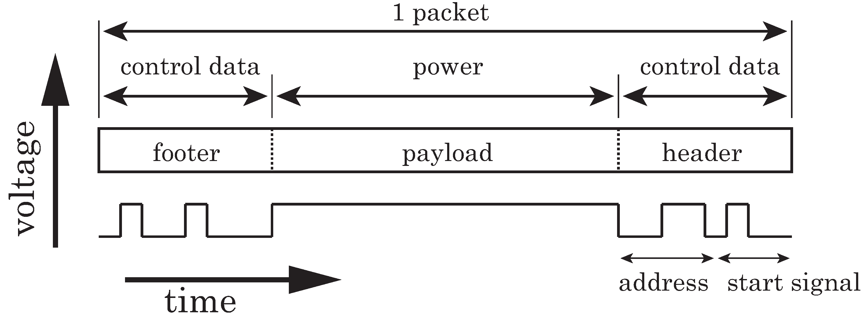
The structure of the power packet is depicted in the time domain in
Figure 1 [
2]. The amount of supplied power per packet is regulated by changing the length of the payload or modulating the payloads. The header and footer are physically attached to the payload as a tag. The tag contains several pieces of information such as the address of the source and the destination of the load. The footer is the mark of the end of the packet. The electric power and the information tag are transferred together in a packet in the same physical layer.
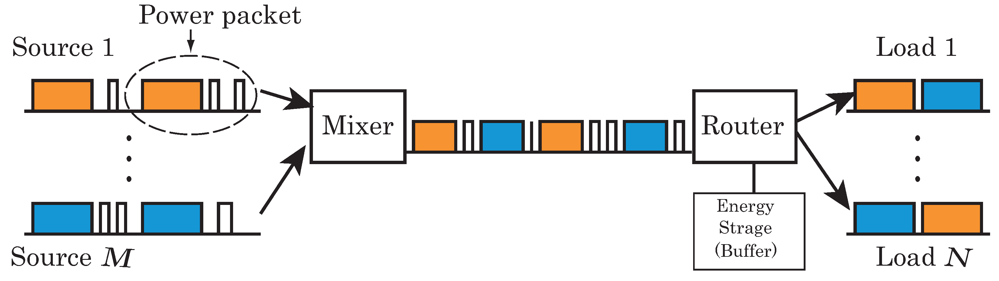
Figure 2 shows a conceptual diagram of the power packet dispatching system. The system consists of multiple power sources, multiple loads, a mixer, a router, and a distribution line between the mixer and router. Each of these sources and loads is assigned a unique address.
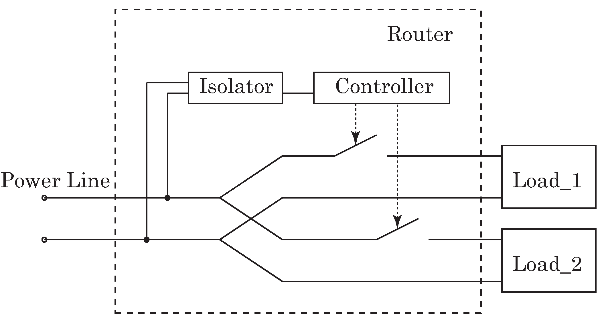
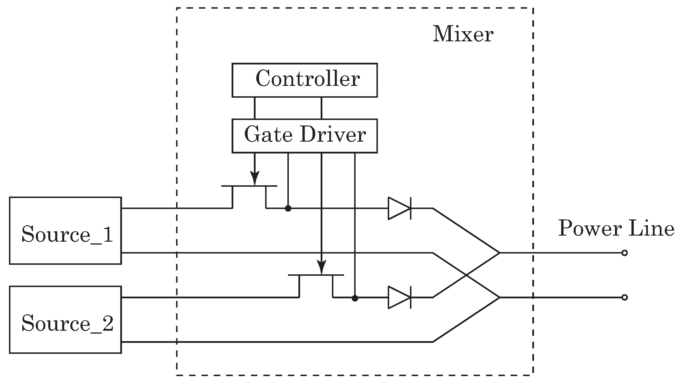
Figure 3 and
Figure 4 depict the circuit diagram of the mixer used in the experiment and a schematic diagram of the router shown in [
2], respectively. The mixer has already been implemented and tested. The mixer sorts the packets from various sources to prevent overlapping of the payloads by controlling the switches on the lines. Thus, the mixer performs the time-division multiple access (TDMA). The router receives the packets and reads each header and footer. The router controls its switches according to the address included in the header and sends the power packets to the objective loads.
Figure 1.
Structure of the power packet.
Figure 1.
Structure of the power packet.
Figure 2.
Concept of the power packet dispatching system.
Figure 2.
Concept of the power packet dispatching system.
Figure 3.
Schematic of the mixer.
Figure 3.
Schematic of the mixer.
This power packetization leads to the
digitization of electrical power transfer system.
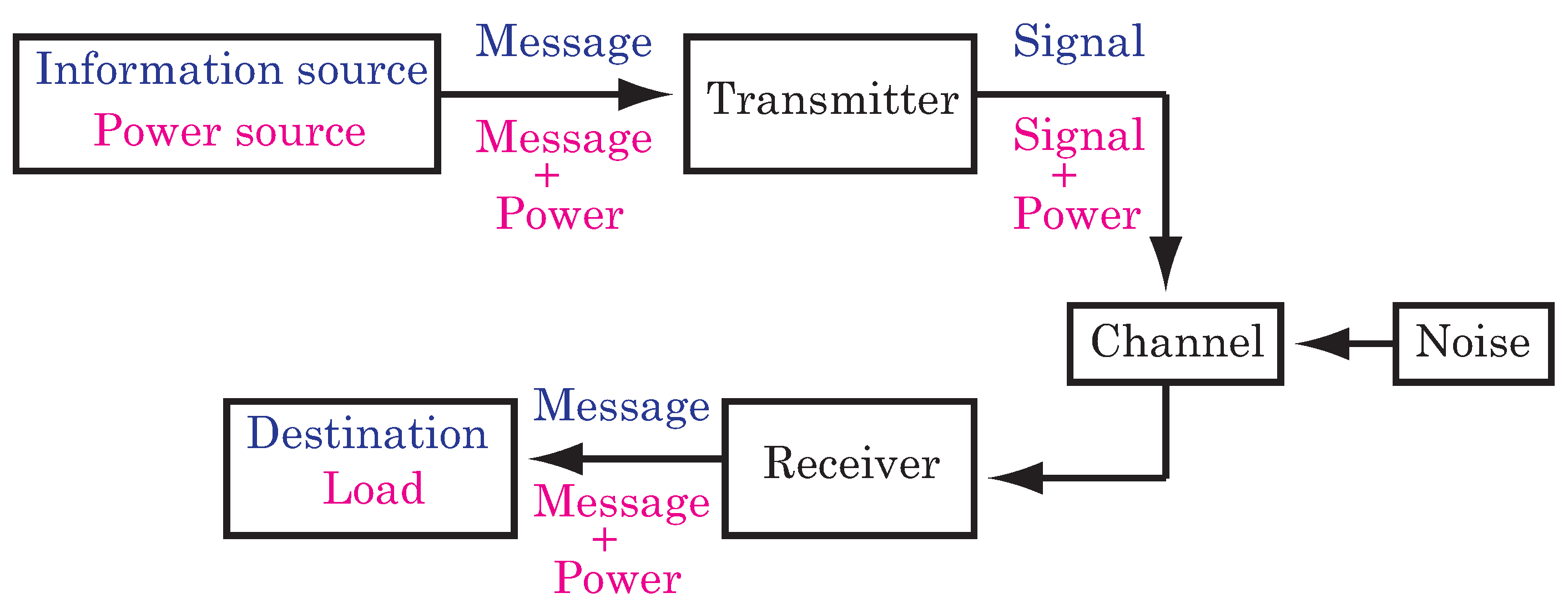
Figure 5 shows a schematic diagram of the proposed power packet dispatching system in the general communication system by Shannon [
7]. With a digitized power transfer system, a similar theory based on Shannon’s communication theory may be applied and will be the target of our future study. At the same time, it is worth noting that power packetization can apply
coloring of the electric power,
i.e., each load can receive the power delivered from a source suitable to its requirements.
Figure 4.
Schematic of the router.
Figure 4.
Schematic of the router.
Figure 5.
Schematic diagram comparing a general communication system and a power packet dispatching system. Communication and power packet dispatching systems are indicated in blue (upper) and red (lower), respectively.
Figure 5.
Schematic diagram comparing a general communication system and a power packet dispatching system. Communication and power packet dispatching systems are indicated in blue (upper) and red (lower), respectively.
3. Indoor Power Line Channel
Recently, the propagation characteristics of power line channels have been investigated in the context of power line communication [
8,
9,
10]. Tsuzuki
et al. estimated the transfer function of indoor power line channels [
8].
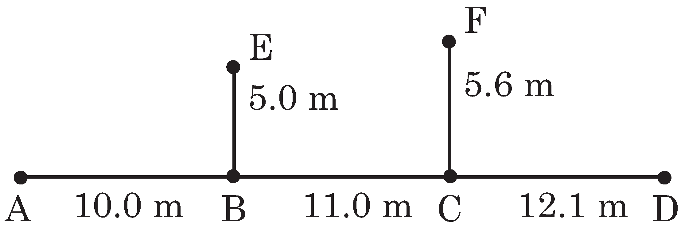
Figure 6 shows one of the configurations of these channels. The power line is a VVF cable with two wires of
mm, which is widely used for indoor power lines in Japan. The signal is transmitted and received at points A and D. At points E and F, appliances can be connected. Impedance mismatching causes a signal reflection, which results in a frequency selective fading response in the power line channel. In [
8], the practical mathematical model of the transfer function is developed for the VVF cable by adopting measured parameters.
Here, we consider two configurations for dispatching power packets based on the model obtained in [
8]. One is the branched configuration shown in
Figure 6. The other is the branch-less configuration based on the above model,
i.e., a straight VVF cable stretched between points A and D. The transfer function of the branch-less model can be obtained by adopting the parameters of the above model. We assume that a power source and a destination load are set at points A and D, respectively. A mixer is set between the source and the power line, and a router is also set between the power line and the load. Ideally, the mixer and the router are assumed to be included in the source and load, respectively. The impedances are matched among the VVF cable, the switches in the mixer and router, the internal resistance of the source, and the destination load. Thus, there is no signal reflection at the junction points among these elements. Here we focus on the power line configurations between the mixer and router. In the branched configuration, we assume open-ended branches with no appliances.
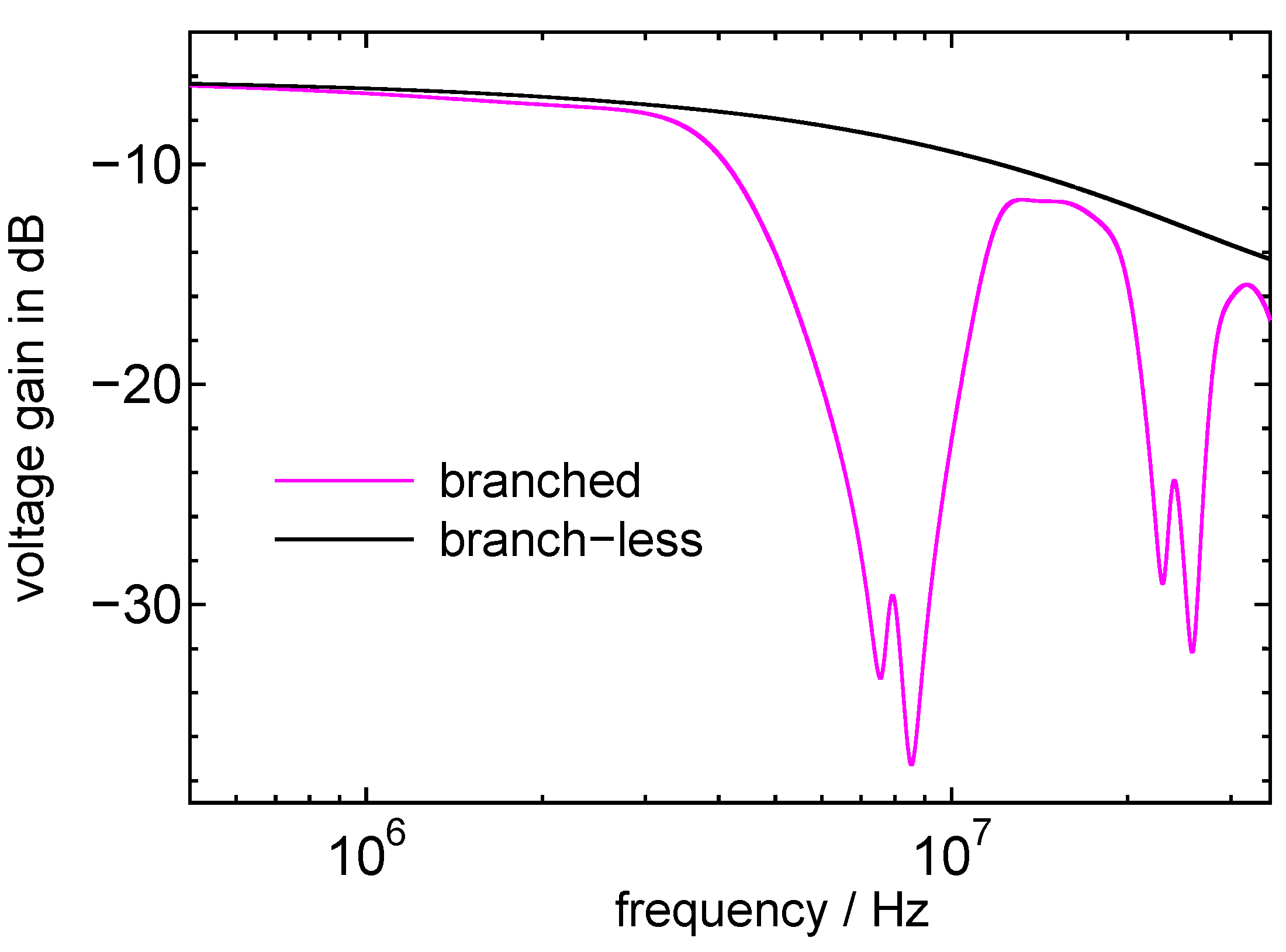
Figure 7 shows the voltage gains for the configurations. The sharp drops in voltage gain are caused by resonance.
Figure 6.
Power line configuration.
Figure 6.
Power line configuration.
Figure 7.
Voltage gain for the power line channel.
Figure 7.
Voltage gain for the power line channel.
4. Efficiency of Power Packet Transmission
In the power packet dispatching system, the electrical power is transferred by a pulse-shaped voltage as shown in
Figure 1. The efficiency of the power packet transmission can be estimated for the pulse wave transfer in the power line channel. For the estimation, two types of pulse are introduced. One is a rectangular pulse applied to the power transmission, because of hard switching of voltage or current. The duty cycle
D is set at
. Positive and negative voltage pulses are transmitted randomly through the power line channel. The other is a sinusoidal-wave for power transmission. To estimate the efficiency of the power transmission, we calculated the ratio of the power consumed at the destination load to the input power into the power line channel described in
Section 3. Here, the impedance of the load is matched to the characteristic impedance of the power line cable.
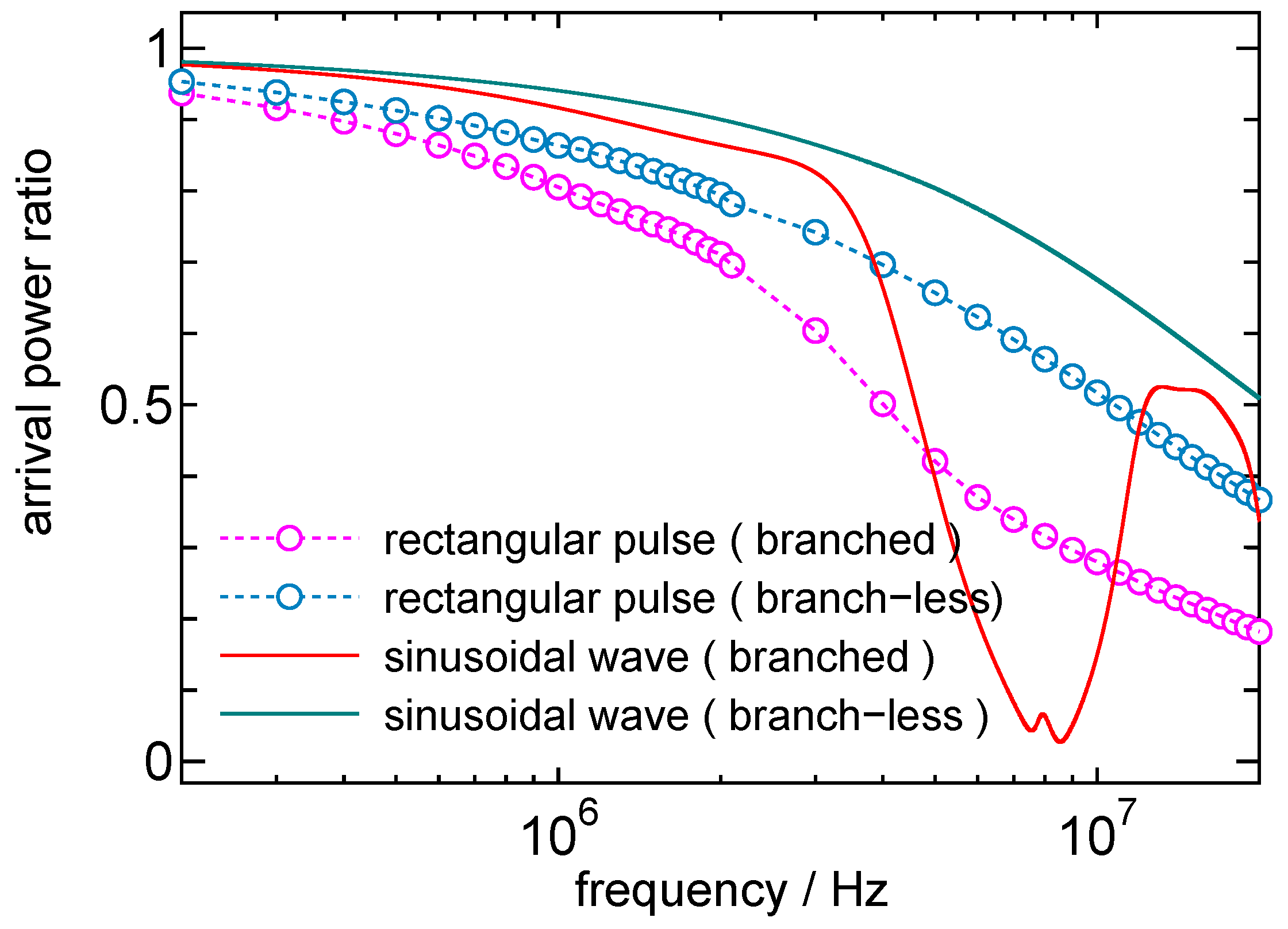
Figure 8 shows the power ratio arriving at the load as functions of frequency. Compared with the branch-less channel, the branched channel shows the less efficiency at the load than the expected in
Figure 7. The rectangular pulse displays slightly poorer power transmission characteristics than the sinusoidal-wave. However, around the resonance frequency in the branched configuration, the rectangular pulse can dispatch much more power than the sinusoidal-wave. This is because the rectangular pulse consists of broad spectrum components. At frequencies of 1 MHz or less, both the rectangular pulse and the sinusoidal wave seem to retain more than
of the incoming power. It is worth noting that conventional power distribution from dispersed power sources to loads wastes more than
of generated power during power conversions.
Figure 8.
Arrival power ratio for rectangular pulse and sine wave.
Figure 8.
Arrival power ratio for rectangular pulse and sine wave.
5. Bit Error Rate of the Information Signal in the Power Packet
The power packet includes the information signal which is temporally attached to the power payload as header and footer. Here, we assume that the original pulses are rectangular waves, because signal pulses are also generated by turning on and off in circuits like payload. In addition, the raised cosine (RC) pulse is also considered as one of the band-limitation pulse shapes.
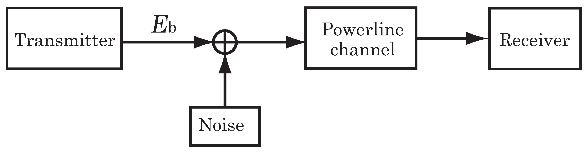
Figure 9 is a schematic diagram of the model investigated here. We transmit the positive and negative pulses randomly through the power line channel, using the branched and branch-less channels (
Figure 6). The noise is assumed to be white Gaussian noise and is added at the start of the power line channel. A matched filter is set at the receiver. The input impedance of the receiver is set to match that of the VVF cable. At the above settings bit error rates (BERs) are calculated by numerical simulation.
Figure 9.
Schematic diagram of the model investigated here.
Figure 9.
Schematic diagram of the model investigated here.
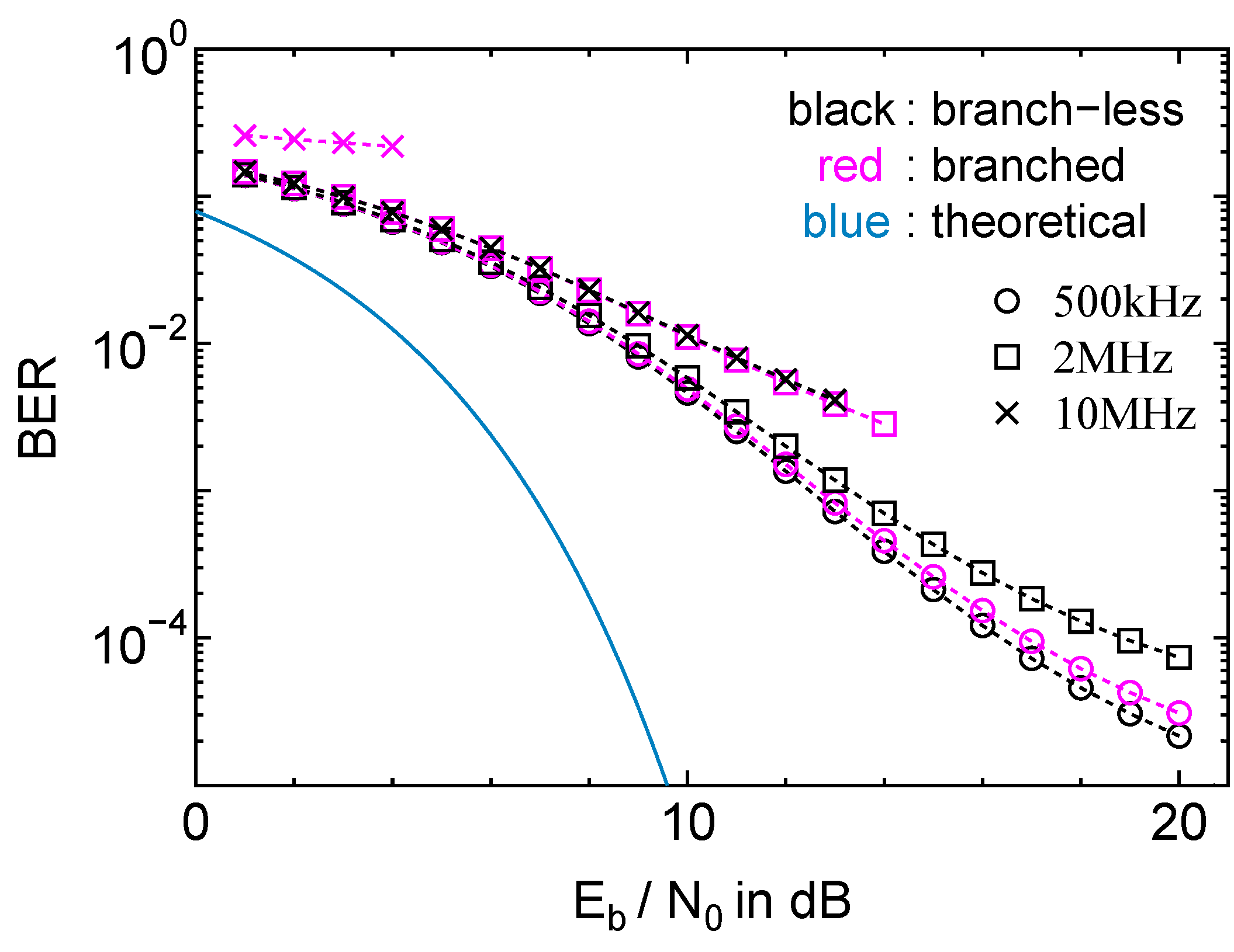
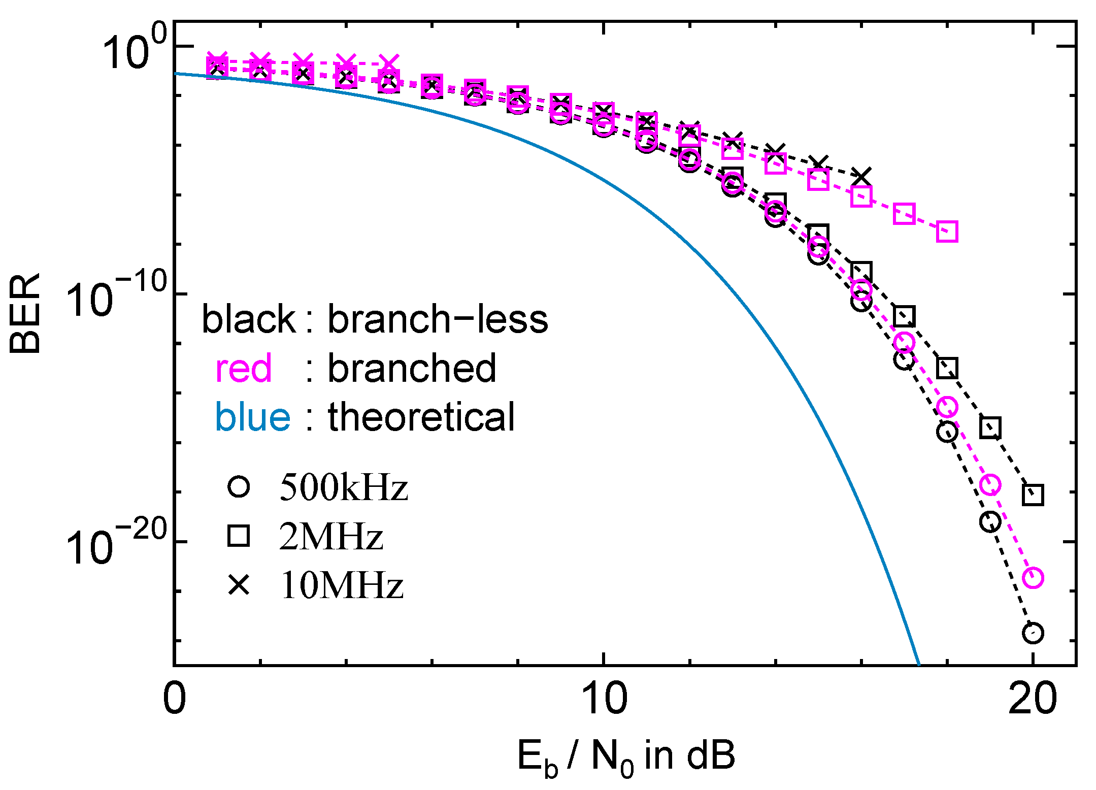
Figure 10 and
Figure 11 show the BER as functions of bit energy at transmitter over noise power
for the rectangular and RC pulses, respectively. The theoretical BER is obtained by
. Because of the power loss in the power line channel, the rectangular and RC pulses perform worse than in the theoretical calculations. The rectangular pulse has a lower BER than the RC pulse. Although there is no bandwidth limitation for the rectangular pulse, in practice it is necessary to apply band-limited pulse shaping, similar to that of the RC pulse. In both cases, it is clear that the branch-less channel performs better than the branched channel. These results are important when designing the signal part of the packet with respect to the number of bits in the header and footer. For example, the required bit energy can be estimated at the transmitter to obtain the desired BER.
Figure 10.
Bit error rate for rectangular pulse.
Figure 10.
Bit error rate for rectangular pulse.
Figure 11.
Bit error rate for RC pulse.
Figure 11.
Bit error rate for RC pulse.
6. Discussion and Conclusions
We investigated the transfer property of the power packet for indoor power line channels. Two fundamental power line network configurations—branched and branch-less—were considered. We used two-wire VVF electric cable, which is generally adopted for home power lines in Japan. We assumed matched impedance among the cables, the internal resistance in the packet transmitter and destination load. In the branched configuration, no appliance connection is assumed at the ends of branches except the destination load. We investigated the BER and the ratio between the power at the source and at the load by numerical simulations for the two system configurations.
This power packet system is intended to be implemented in a DC power delivery system. The power packet is formed by an on–off switch connected to the DC power sources. Currently, AC power distribution systems lose more than power because of power conversion. Our investigation shows that more than of the source power can be dispatched to the destination load at frequencies up to 1 MHz for both the branched and branch-less channels used in this study. In addition, “coloring" and routing can be obtained by using the power packet, enabling the balancing of the power quality between the source and the load. Initially, power distribution is considered inside a small unit such as a home or a building with an independent power line from the commercial power system. From the BER evaluation, it is possible to estimate the bit energy at the transmitter to obtain the desired BER. This estimation makes it possible to estimate the number of bits that can be used as the header and footer. In the power packet dispatching system, the mixer and router are set at the connection point of the source, load, and power line. Here, the mixer and router are assumed to be included in the source and load, respectively. In practice, the impedances of the mixer and router are not always matched with the other impedances such as the internal resistance of the source. The impedance mismatching causes the reflection of voltage or current, and changes the transfer function of the channel. Moreover, the switching generates noise in the channel. The effects of switching noise and impedance mismatching at the sources, loads, mixers, and routers on the power packet dispatching system will be considered as a future topic of this study.
The concept of power packetization and its routing leads to the digitization of the power transfer itself. For this, a more effective digital modulation method will be needed. Depending on the number of the sources and loads, other channel access methods may be used, apart from TDMA. The flow of the power packet contains a wealth of information on people’s private daily consumption habits. Thus, the power packet system requires highly secure structure. The security of the system is a further topic to be discussed in this research. To implement the system, high-voltage and high-frequency power switching device are essential to the power packet. In addition, the switching devices should be as energy efficient as possible. Simultaneously, experimental verification is also important. The generation of power packets has already been verified in experiments in laboratory and in residential houses [
2,
4]. The implementation of SiC power devices depends on the system ratings. It has the benefit of low power loss for high frequency applications.
The power packets have the potential to achieve efficient power transfer to the objective load. It is considered that the power packet routing system can achieve the on-demand home energy networking requirements [
11]. It is also possible to stop the power supply to idling loads and save wasted electricity because of the path selection and bi-directional characteristics attained by the power packet transmission. This power packet transfer system makes it possible to control the flow of electric power in the form of discretization. In this study, we focus on one source and one load connection as a small network unit. In this unit, the packet routing control is not considered. In a practical network system, it would be necessary to consider the routing algorithm and its evaluation, e.g., [
11,
12]. The expansion of network is also future topic in our research. We expect to obtain an effective decrease in energy loss and to be able to select power sources without mixing power by using power packetization and its routing.
