Article

Collector Efficiency in Downward-Type Double-Pass Solar Air Heaters with Attached Fins and Operated by External Recycle

Energy and Opto-Electronic Materials Research Center, Department of Chemical and Materials Engineering, Tamkang University, Tamsui, New Taipei 251, Taiwan
*
Author to whom correspondence should be addressed.
Energies 2012, 5(8), 2692-2707; https://doi.org/10.3390/en5082692
Submission received: 30 April 2012 / Revised: 4 June 2012 / Accepted: 19 July 2012 / Published: 26 July 2012

Abstract

:
The collector efficiency in a downward-type double-pass external-recycle solar air heater with fins attached on the absorbing plate has been investigated theoretically. Considerable improvement in collector efficiency is obtainable if the collector is equipped with fins and the operation is carried out with an external recycle. Due to the recycling, the desirable effect of increasing the heat transfer coefficient compensates for the undesirable effect of decreasing the driving force (temperature difference) of heat transfer, while the attached fins provide an enlarged heat transfer area. The order of performances in the devices of same size is: double pass with recycle and fins > double pass with recycle but without fins > single pass without recycle and fins.

1. Introduction

In addition to the essential effects of free and forced convections [1,2,3], considerable improvement in collector efficiency is also achievable by attaching fins to increase the heat transfer area [1,4], and by using baffles [5], or the matrix [6] to create the turbulent inside the flow channel. It was pointed out that applications of multi-pass [7,8,9] or recycle operation [10,11,12,13,14,15,16] can effectively enhance the performances of heat and mass transfer due to the increase in fluid velocity. The effect of external recycle on the performances in the single-pass [17] and double-pass [18] solar air heaters has been investigated. Considerable improvement in collector efficiency is obtainable if the operation is carried out with an external recycle, where the desirable effect of increasing fluid velocity can generally compensate for the undesirable effect of decrease in heat-transfer driving force (temperature difference) due to remixing by recycle operation. It is the purpose of this work to further investigate the performance in a downward-type double-pass external-recycle solar air heater with fins attached on the absorbing plate.

2. Theoretical Analysis

Consider a recycling double-pass solar air heater with n fins attached on the absorbing plate, as shown in Figure 1. The width, length and height of the flow channel are B, L and H, respectively. An insulated plate with negligible thickness is placed vertical to the absorbing plate and bottom plate, at the centerline to divide the flow channel into subchannel 1 and subchannel 2 of equal width B/2, and that a pump is installed for recycle with reflux ratio R. For a double-pass operation with external recycle, before entering subchannel 1, the airflow with mass flow rate m ˙ and inlet airflow temperature Ti will mix with part of the airflow exiting from subchannel 2 with mass flow rate m ˙ R and outlet airflow temperature Tfo. The following assumptions are made in the analysis: (1) the absorbing-plate, bottom-plate and bulk-fluid temperatures are functions of the flow direction (z) only; (2) both glass cover and fluid do not absorb radiant energy; (3) except the glass cover, all parts of the outside surface of solar air collector, as well as the thin plate for separation subchannels 1 and 2, are well thermally insulated; (4) the physical properties of the fluid and materials are constant; and (5) steady state operation.
Figure 1. Schematic diagram of a downward-type double-pass external-recycle solar air heater with fins attached.
Energies 05 02692 g001

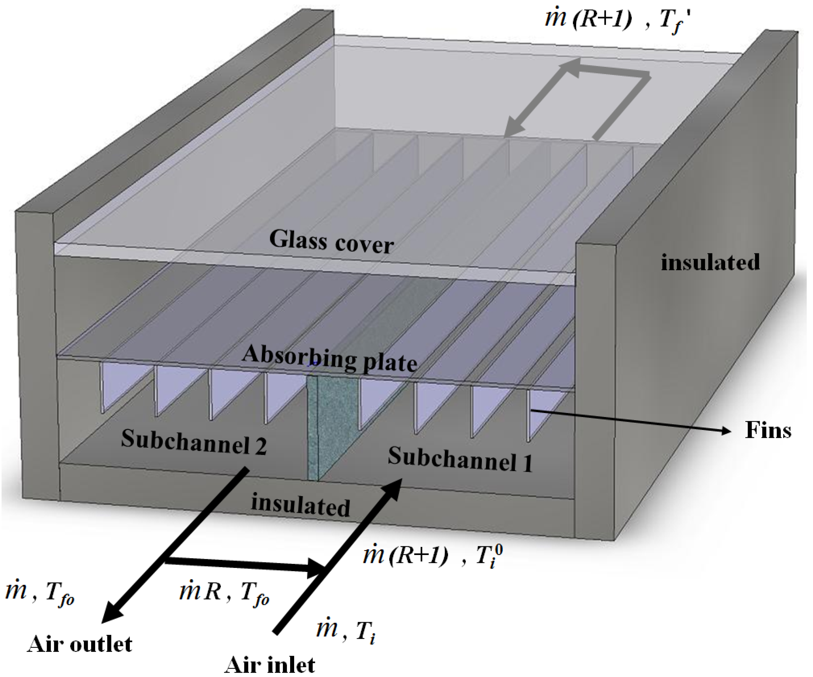
2.1. Temperature Distribution for the Fluid in Subchannel 1

The steady-state energy balance for a differential section of the absorbing plate with n fins attached, bottom plate and flowing fluid are, respectively:
I 0 τ g α p ( B / 2 ) d z = h ϕ ( B / 2 ) d z ( T p T f 1 ) + h r , p R ( B / 2 ) d z ( T P T R ) + U t ( B / 2 ) d z ( T p T a )
h r , p R ( B / 2 ) d z ( T P T R ) = h ( B / 2 ) d z ( T R T f 1 )
[ m ˙ ( 1 + R ) C p ]( d T f 1 d z ) d z = h ϕ ( B / 2 ) d z ( T p T f 1 ) + h ( B / 2 ) d z ( T R T f 1 )
where:
ϕ = 1 + ( A f / A c ) η f
in which Af (= 2nw2L) and Ac (= BL) are the surface areas of fins and absorbing plate, respectively, while ηf denotes the fin efficiency [19], i.e.:
η f = ( tanh M w 2 ) / M w 2
and:
M = 2 h / k s t
where w2 and ks are the height of a fin and thermal conductivity of the absorbing plate and fins, respectively, while t is the fin thickness.
Solving Equations (1) and (2) for (Tp − Tf1) and (TR − Tf1):
T p T f 1 = I 0 τ g α p ( h + h r , p R ) ( h U t + h r , p R U t )( T f 1 T a ) h ϕ ( h + h r , p R ) + h ( h r , p R + U t ) + h r , p R U t
T R T f 1 = I 0 τ g α p h r , p R h r , p R U t ( T f 1 T a ) h ϕ ( h + h r , p R ) + h ( h r , p R + U t ) + h r , p R U t
The detailed explanation in the derivations of Equations (7) and (8) are expressed mathematically and shown in Appendix. Substituting Equations (7) and (8) into Equation (3), we have:
[ 2 m ˙ ( 1 + R ) C P ) ] d T f 1 d z = B F [ I 0 τ g α p U t ( T f 1 T a ) ] = 0
where:
F = h ϕ ( h + h r , p R ) + h h r , p R h ϕ ( h + h r , p R ) + h ( h r , p R + U t ) + h r , p R U t
in which F' is called collector efficiency factor, which is essential constant for any design and fluid flow rate [20], and Ut is the loss coefficient from the top of the solar collector to the ambient. If Ut is assumed to be constant along the flow direction, Equation (9) can be easily integrated for the boundary condition:
T f 1 = T i 0   at   z = 0
The result is:
T f 1 T a ( I 0 τ g α p / U t ) T i 0 T a ( I 0 τ g α p / U t ) = exp [ F U t B z 2 m ˙ ( 1 + R ) C p ]
Equation (12) is the temperature distribution of the bulk fluid along the flow direction of subchannel 1. Thus, the fluid temperature at the outlet of subchannel 1 is readily obtained from Equation (12) by substituting the condition: Tf1 = T'f at z = L. The result is:
T f T a ( I 0 τ g α p / U t ) T i 0 T a ( I 0 τ g α p / U t ) = exp [ F U t A c 2 m ˙ ( 1 + R ) C p ]
where Ac = BL = nw1L, surface area of the absorbing plate.

2.2. Temperature Distribution for the Fluid in Subchannel 2

The differential energy-balance equation for the fluid in subchannel 2 is readily obtained by following the same procedure from Equation (1) through Equation (13) with Tf1 and (dTf1/dz) replaced by Tf2 and-(dTf2/dz), respectively. The result is:
[ 2 m ˙ ( 1 + R ) C p ] d T f 2 d z = B F [ I 0 τ g α p U t ( T f 2 T a ) ]
Integrating Equation (14) with the use of the boundary condition:
Tf2 = Tfo at z = 0
one has the temperature distribution for the fluid in subchannel 2 as:
T f 2 T a ( I 0 τ g α p / U t ) T f o T a ( I 0 τ g α p / U t ) = exp [ F U t B z 2 m ˙ ( 1 + R ) C p ]
Thus, in addition to Equation (13), the fluid temperature T'f at the inlet of subchannel 2 (z = L) is also obtained from Equation (16) by substituting z = L and Tf2 = T'f. The result is:
T f T a ( I 0 τ g α p / U t ) T f o T a ( I 0 τ g α p / U t ) = exp [ F U t A c 2 m ˙ ( 1 + R ) C p ]

2.3. Collector Efficiency and Fluid Outlet Temperature

The fluid outlet temperature is readily obtained by combining Equations (13) and (17) to eliminate T'f as:
T f o T a ( I 0 τ g α p / U t ) T i 0 T a ( I 0 τ g α p / U t ) = exp [ F U t A c m ˙ ( 1 + R ) C p ]
Two different expressions for the useful again of energy Qu carried away by air can be obtained as:
Q u = m ˙ C p ( T f o T i 0 )
= m ˙ ( 1 + R ) C p ( T f o T i 0 )
Inspection of Equation (19) shows that the mixed inlet temperature Ti0 due the recycle is not specified a prior. The relation for the mixing effect at the inlet in Equation (20) was used for determination of this value. Thus, a combination of Equations (19) and (20) gives:
T i 0 = T f o ( T f o T i )/( 1 + R ) = T i + [ R / ( 1 + R )]( T f o T i )
The collector efficiency may be defined as:
η c f = Q u I 0 A c = [ m ˙ ( 1 + R ) C p / I 0 A c ]( T f o T i 0 )
or
η c f = m ˙ C p ( T f o T i ) / I 0 A c
Substitution of Equation (18) into Equation (22) gives:
η c f = m ˙ ( 1 + R ) C p I 0 A c {[ T a + ( I 0 τ g α p / U t ) T i 0 ]                        + [ T i 0 T a ( I 0 τ g α p / U t )] exp [ A c F U t / m ˙ ( 1 + R ) C p ]}
= F R [ τ g α p U t ( T i 0 T a ) / I 0 ]
where the heat-removal factor for solar air heater is defined as:
F R = [ m ˙ ( 1 + R ) C p / A c U t ]{ 1 exp [ A c F U t / m ˙ ( 1 + R ) C p ]}
Substitution of Equation (21) into Equation (24) with the aid of Equation (18) to eliminate Ti0 and Tfo yields:
η c f = F R [ τ g α p U t ( T i T a ) / I 0 ] 1 + ( F R U t A c / m ˙ C p )[ R / ( 1 + R )]
Once the collector efficiency is determined, the fluid outlet temperature is readily obtainable from Equation (23), i.e.:
T f o = T i + ( η c f I 0 A c / m ˙ C p )

2.4. Mean Fluid and Absorbing-Plate Temperatures

The mean fluid and absorbing-plate temperatures are needed for calculating the heat-transfer coefficients. The mean-fluid temperature may be defined as:
T f m = 1 2 L 0 L ( T f 1 + T f 2 ) d z
Substituting Equations (12) and (16) into Equation (28) and integrating, we have:
T f m = m ˙ ( 1 + R ) C p F U t A c { ( T i 0 T a I 0 τ g α p U t ) [ 1 exp ( F U t A c 2 m ˙ ( 1 + R ) C p ) ]            + ( T f o T a I 0 τ g α p U t ) [ exp ( F U t A c 2 m ˙ ( 1 + R ) C p ) 1 ] } + ( T a + I 0 τ g α p U t )
With the use of Equations (23) and (24) to eliminate Tfo and Ti0, respectively, Tfm in Equation (29) can be expressed in term of ηcf as:
T f m = m ˙ ( 1 + R ) C p F U t A c { ( I 0 η c f F R U t ) [ exp ( F U t A c 2 m ˙ ( 1 + R ) C p ) 1 ]            + [ ( η c f I 0 A c m ˙ C p ) + ( T i T a I 0 τ g α p U t ) ]   [ exp ( F U t A c 2 m ˙ ( 1 + R ) C p ) 1 ] } + ( T a + I 0 τ g α p U t )
The mean absorbing-plate temperature may be defined in term ηcf as:
η c f = τ g α p U t ( T p m T a ) / I 0
or:
T p m = T a + ( I 0 / U t ) ( τ g α p η c f )
Equations (30) and (32) are the expressions of Tfm and Tpm in terms of ηcf.

2.5. Heat-Transfer Coefficients

The convective heat-transfer coefficient hw for air flowing over the outside surface of the glass cover depends primarily on the wind velocity V. McAdams [21] obtained the experimental result as:
hw = 5.7 + 3.8 V
An empirical equation for the loss coefficient from the top of the solar collector to the ambient UL was developed by Klein [22] following the basic procedure of Hottel and Woertz [23]. For the horizontal collector shown in Figure 1:
U t = { T p m / 520 [ ( T p m T a ) 1 + ( 1 + 0.089 h w 1.1166 h w ε p ) ( 1 + 0.07866 ) ] 0.43 ( 1 100 / T p m ) + 1 h w } 1 + σ ( T p m T a ) ( T p m 2 + T a 2 ) 1 ( ε p 0.00591 h w ) + 2 + ( 1 + 0.089 h w 0.1166 h w ε p ) ( 1 + 0.07866 ) 1 + 0.133 ε p ε g 1
The radiation coefficient between the two air-duct surfaces may be estimated by assuming a mean radiant temperature equal to the mean fluid temperature [20]:
h r , p R = 4 σ T f m 3 1 ε p + 1 ε R 1
In the study of solar air heaters and collector-storage walls, it is necessary to know the forced convection heat-transfer coefficient between two flat plates. For air, the following correlation may be derived from Kays’ data for fully developed turbulent flow with one side heated and the other side insulated [24]:
Nu = hDe/k = 0.0158 Re0.8
where the equivalent diameter of the ducts are:
D e , 1 = D e , 2 = 4 ( H B / 2 ) 2 ( H + B / 2 ) = 2 H B 2 H + B
and the average air velocities in subchannels 1 and 2 for double-pass operation are:
v 1 ¯ = v 2 ¯ = 2 m ˙ ( 1 + R ) H B ρ
Thus, from Equations (37) and (38), one obtains the Reynolds numbers for the rectangular ducts as:
Re 1 = Re 2 = 4 m ˙ ( 1 + R ) μ ( 2 H + B )

2.6. Calculation Method for ηcf and Tfo

The calculation of prediction values for collector efficiency and outlet fluid temperature is now described as follows. First, with known collector geometries (L,B,H) and system properties ( τ g , α p , C p , ρ , μ , k , k s , ε p , ε g , ε R ) , as well as the given operating conditions ( I 0 , T a , V , m ˙ , R , T i , n ) , a temporary value of ηcf is estimated from Equation (26) once Tfm and Tpm are assumed. The values of Tfm and Tpm are then checked by using Equations (30) and (32), respectively, and new values of Tfm and Tpm may be obtained. If the calculated values for Tfm and Tpm are different from the assumed values, continued calculations by iteration is needed until the last assumed values meet the finally calculated values, and thus the corresponding value for ηcf is also finally obtained. Once the correct value of ηcf is obtained, the outlet fluid temperature is readily calculated from Equation (27).
The following flow sheet may be helpful for simply expressing the calculation procedure:
Given  { τ g , α p , C p , ρ , μ , k , k s , ε p , ε g , ε R , I 0 , T a , V , m ˙ , R , T f , i , n } Equation (26) with  T f m  and  T p m  assumed η c f Equation (32) Equation (30) T f m T p m Equation (27) Equation (20) Q u T f o  and  η c f

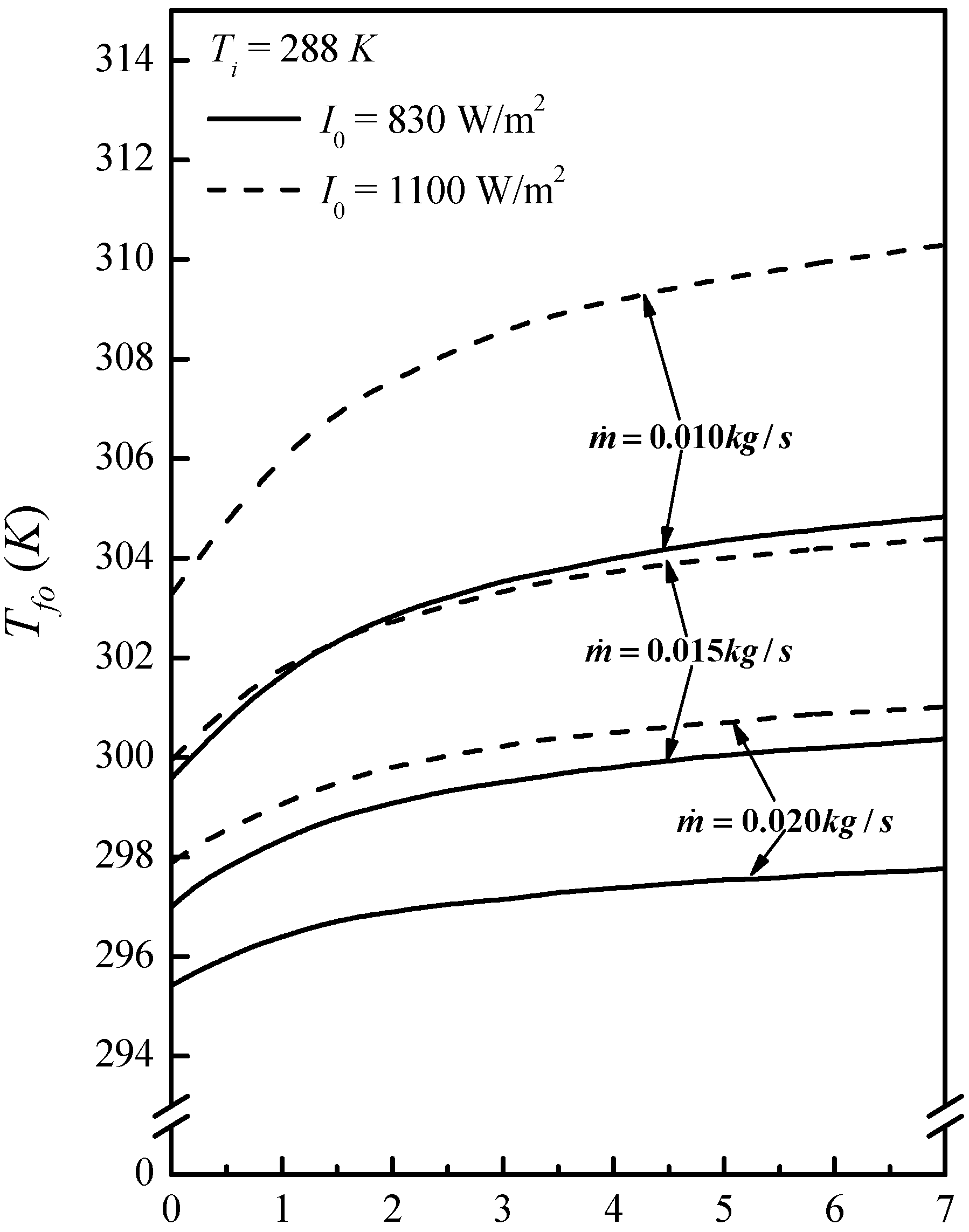
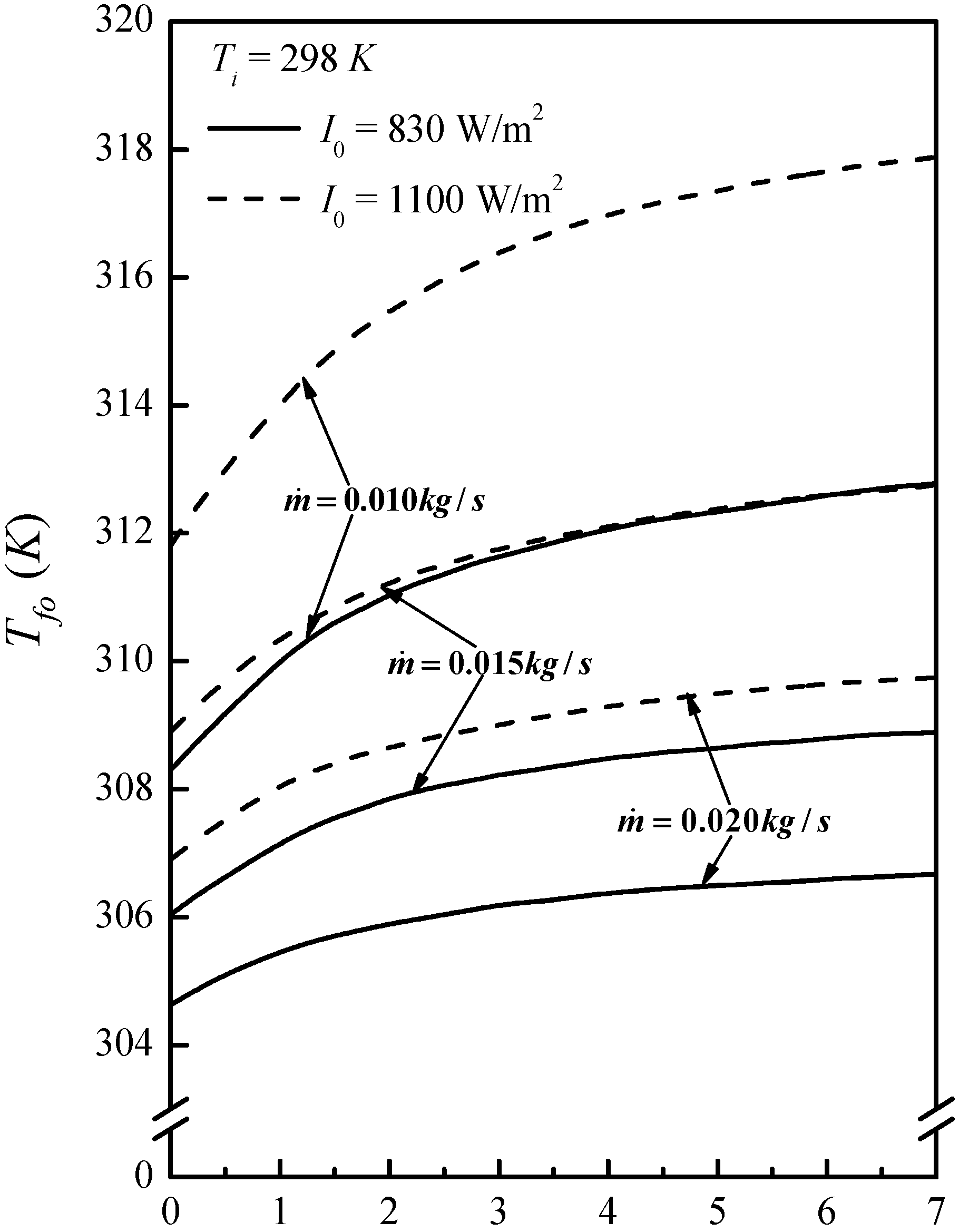
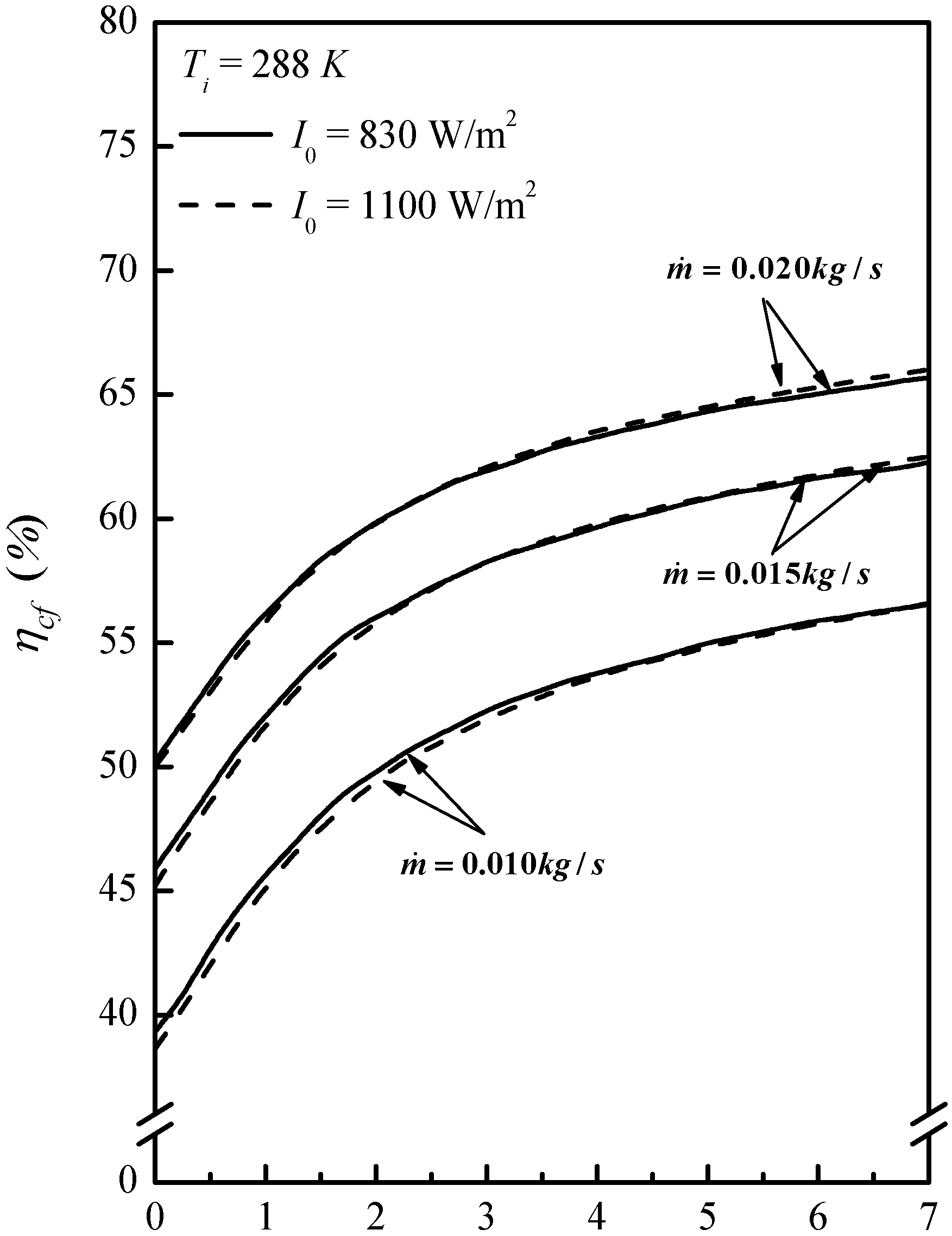
3. Results and Discussion

3.1. Numerical Example

The improvement in performance of an external-recycle double-pass solar air heater with n fins attached on the absorbing plate may be illustrated numerically by using Table 1 and the following design and operating conditions: L = B = 0.6 m; Ac = LB = 0.36 m2; H = 0.05 m; w1 = 0.05 m; w2 = 0.02 m; t = 0.001 m; ks = 45 W/mK; n = 12; τg = 0.875; αp = 0.95; εg = 0.94; εp = 0.95; εR = 0.94; I0 = 830 and 1100W/m2; Ti = 288, 293 and 298 K; V = 1 m/s; m ˙ = 0.01 , 0.015 and 0.02 kg/s; Ta = 283 K, σ = 5.67 × 10⁻⁸ W/m2 K4.
Table 1. Physical properties of air at 1 atm [20].
T (K)ρ (kg/m3)Cp (J/kg K)k (W/m K)μ (kg/m s)
2731.29210060.02421.72 × 10−5
2931.20410060.02571.81 × 10−5
3131.12710070.02721.90 × 10−5
3331.05910080.02871.99 × 10−5
3530.99910100.03022.09 × 10−5
By substituting the specified values into the appropriate equations with the use of Table 1 for the physical properties of air, theoretical predictions for collector efficiency and outlet air temperature were obtained.

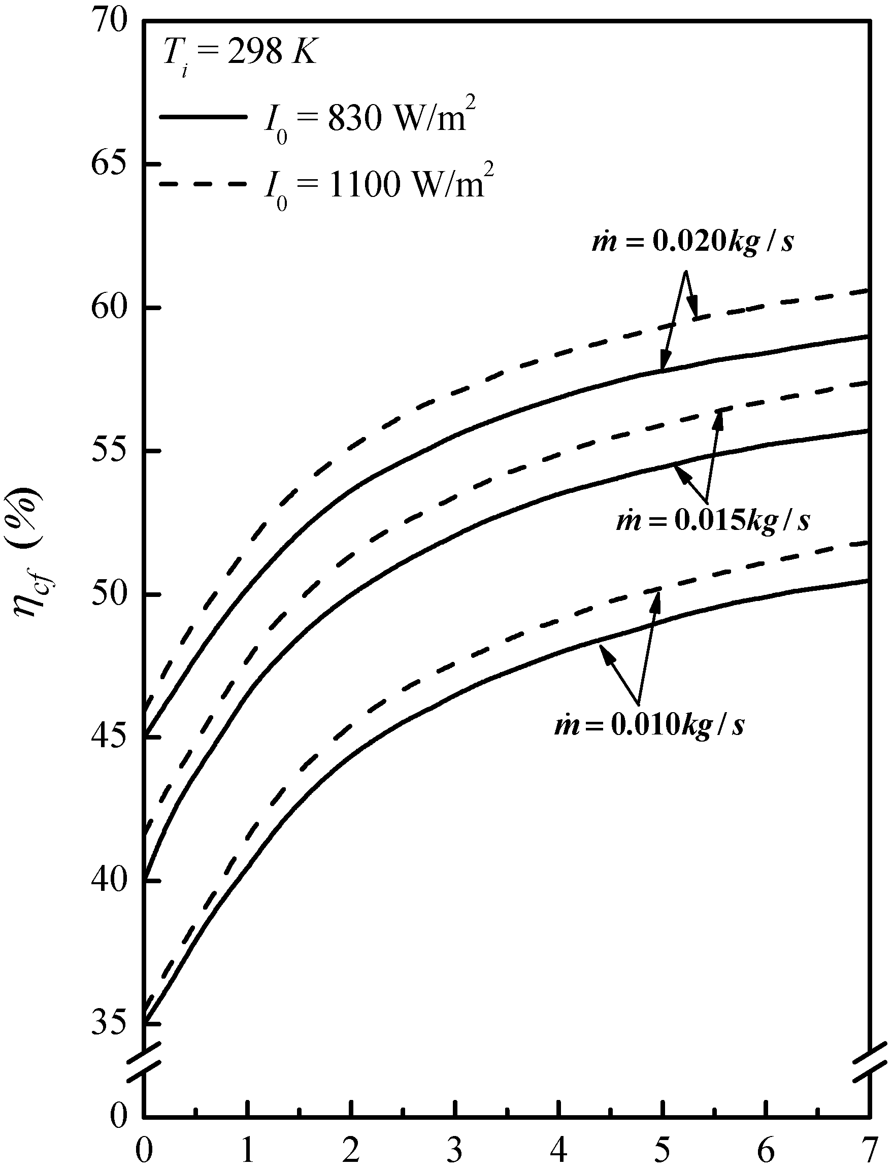
3.2. Effects of Operating Parameters on Collector Efficiency

As might be expected, the outlet air temperature Tfo increases with the inlet air temperature Ti, resulting in decrease in collector efficiency ηcf.
Figure 2. Air outlet temperature (Ti = 288 K).
Energies 05 02692 g002
Figure 3. Air outlet temperature (Ti = 298 K).
Energies 05 02692 g003
Figure 4. Collector efficiency (Ti = 288 K).
Energies 05 02692 g004
Figure 5. Collector efficiency (Ti = 298 K).
Energies 05 02692 g005
On the other hand, the outlet air temperature decreases when the air flow rate m ˙ increases in which the collector efficiency increases. Of course, both the outlet air temperature and collector efficiency increase when the solar radiation incident I0 increases. These results are shown in Figure 2, Figure 3, Figure 4 and Figure 5.

3.3. Improvement in Performance by Recycling

The improvements If and I in collector efficiencies (ηcf and ηc) by using the double pass recycled collectors with and without fins attached are best illustrated by calculating the percentage increase in collector efficiency based on η0 obtained in the single-pass device of same size, operated without recycling and fins attached, i.e.:
I f = collector efficiency of double pass recycled device with fins   η c f collector efficiency of single pass device without recycling and fins   η ¯ c 1
I = collector efficiency of double pass recycled device without fins   η c collector efficiency of single pass device without recycling and fins   η ¯ c 1
The theoretical values of If for the system of present interest with the given values of η0 [17], were calculated using Equation (41), and the results are listed in Table 2. The predicted values for I without fins were already calculated in the previous work [18], and the results are also presented in Table 2 for comparison. From this table and Figure 2, Figure 3, Figure 4 and Figure 5, we see that operating with recycling substantially improves the collector efficiency either with or without fins attached. The improvements increase with increasing reflux ratio R, especially when operating at lower air flow rate m ˙ with higher inlet air temperature Ti. For instances, the improvements of collector efficiency If in the double-pass recycled collector with fins attached and operating at m ˙ = 0.01  kg/s , Ti = 298 K and R = 5, are 123.49% and 129.54%, respectively, for I0 = 830 and 1100 W/m2. It is concluded that the contribution of the desirable effect of increasing fluid velocity by applying the external-recycle operation may be more effective than the undesirable effect of lowering the temperature difference.
Table 2. The improvement of performance for: (a) I0 = 830 W/m2; (b) I0 = 1100 W/m2.
Ti (K) m ˙ (kg/s) η ¯ c (%)If (%) I (%)
R = 0R = 1R = 3R = 5 R = 0R = 1R = 3R = 5
(a)2880.0124.6058.9488.30111.92123.02 36.4968.9197.68111.97
0.01530.3550.3773.5891.6799.99 31.0457.6380.4291.90
0.0234.6544.4763.8878.6685.35 27.3250.3069.6379.00
2930.0123.2858.9488.40119.22123.34 36.5269.3497.93.112.71
0.01528.7550.4173.7692.01100.42 31.1058.0880.9092.56
0.0232.8444.5064.0779.0285.79 27.4050.6770.2979.82
2980.0121.9658.8588.39112.26123.49 36.5169.4098.25112.82
0.01527.1450.3073.7792.15100.63 31.1258.0981.1693.01
0.0231.0244.4164.1179.2086.05 27.4250.6970.3079.95
(b)2880.0123.9261.2192.15117.08119.03 36.4968.8597.53111.77
0.01529.7352.3276.7195.70104.45 31.0457.6380.2891.70
0.0234.1146.0966.3981.8588.85 27.3250.2369.4878.82
2930.0122.9061.2992.34117.39129.17 36.5269.1997.61112.27
0.01528.4852.4283.3996.01104.92 31.1057.9480.6092.15
0.0232.6946.2566.7182.3389.41 27.4050.5269.9879.42
2980.0121.8761.3892.52117.69129.54 36.5169.1797.75112.16
0.01527.2152.5877.2396.52105.43 31.1257.8880.7092.37
0.0231.2646.3366.9282.6989.85 27.4250.4969.8679.38

3.4. Effect of Fin Attached on Device Performance

The improvements I in collector efficiency obtained in a double-pass recycled solar air heater of the same size but without fins attached [18], are also listed in Table 2 for comparisons. It is seen that considerable further enhancement of collector efficiency is achieved if fins are attached on the absorbing plate for increasing the heat transfer area. Taking the case of Ti = 298 K, m ˙ = 0.01  kg/s , I0 = 1100 W/m2 and R = 1 for example, more than 23% improvement (IfI = 92.52 − 69.17%) is obtained when employing the recycled double-pass collector with fins attached, instead of using the same device but without fins, which was employed in the previous work [18]. The further enhancement in collector efficiency E by attaching fins on the absorbing plate may be illustrated, based on the device of same size but without recycle, as:
E = η c f η c η c
Equation (43) may be rewritten using Equations (41) and (42) as:
E = [ ( η c f η ¯ c ) ( η c η ¯ c ) η ¯ c ] ( η ¯ c / η c ) = ( I f I ) ( η ¯ c / η c )
= I f I 1 + I
Some values of E were calculated from Table 2, and the results are listed in Table 3. As seen this table, the further enhancement of the collector efficiency in the device with fins increases with the solar radiation incident I0, while decreases when the air flow sate m ˙ and reflux ratio R increases. The influence of the inlet air temperature Ti on E is not evident.
Table 3. Further enhancement in collector efficiency with fin: (a) I0 = 830 W/m2; (b) I0 = 1100 W/m2.
Ti (K) m ˙ (kg/s)E (%)
R = 0R = 1R = 3R = 5
(a)2880.0116.4511.487.205.21
0.01514.7510.126.244.22
0.0213.479.045.323.55
2980.0116.3711.217.075.01
0.01514.639.926.073.95
0.0213.338.915.233.39
(b)2880.0118.1113.809.907.96
0.01516.2412.108.556.64
0.0214.7410.767.305.57
2980.0118.2213.8010.088.19
0.01516.3712.268.756.79
0.0214.8410.927.555.84

4. Conclusions

The performance in a double-pass solar air heater with external recycling was investigated in a previous work [18]. In the present study the absorbing plate of this device is attached with fins for further improved performance. The predicting equation for the useful gain Qu, the collector efficiency ηcf and the outlet air temperature Tfo, were derived from the energy balance for the absorbing plate, the bottom plate and flowing air. The calculation of ηcf, Tfo and Qu may be generally based on Equations (26), (27) and (20), respectively. The most important assumption is that except for the glass cover, all parts of the outside surface of the solar air collector, as well as the insulated plate for separating two flow channels, are well thermally insulated.
In addition to the double-pass operation with external recycling, further enhancement in collector efficiency is obtainable if the operation is carried out also with fins attached on the absorbing plate. The further enhancement E based on the device without fins, reaches 13.8% for I0 = 1100 W/m2, Ti = 298 K, m ˙ = 0.01  kg/s and R = 1. E decreases when the air flow rate and/or the reflux ratio increase. As expected, therefore, employing the fins attached on the absorbing plate, is ineffective when the performance is operated under large reflux ratio with high air flow rate.
The improvements of collector efficiencies, If and I, in the recycled devices with and without fins attached, increase with increasing reflux ratio, especially for operating at lower air flow rate. It is shown in Table 2 and Figure 2, Figure 3, Figure 4 and Figure 5 that the desirable effect of increasing the fluid velocity by recycle operation compensates for the undesirable effect of decreasing driving force (temperature difference) for heat transfer due to the remixing at the inlet. We can see in Table 2 that about 130% improvement If in collector efficiency is obtained by employing the recycled double-pass solar air heater with fins attached, based on the single-pass device of same size operated without fins. The order of performances in the devices of same size is: double pass with recycle and fins > double pass with recycle but without fins > single pass without recycle and fins.

Nomenclature

Ac
surface area of the absorbing plate, BL (m2)
B
the width of absorber surface area, nw1 (m)
Cp
specific heat of air at constant pressure (J/kg K)
De
equivalent diameter of the channel (m)
E
further improvement in collector efficiency
F'
efficiency factor of the solar air heater
FR
heat-removal factor for the solar air heater
H
height of the air tunnel in the solar collector, or the distance between glass cover and absorbing plate (m)
h
convective feat-transfer coefficient for fluid flowing over the plate of duct (W/m2 K)
hp−R
radiant heat-transfer coefficient between two parallel plates (W/m2 K)
hw
convective heat-transfer coefficient between glass cover and ambient (W/m2 K)
I
improvement in collector efficiency in the device without fins
If
improvement in collector efficiency in the device with fins attached
Io
solar radiation incident (W/m2)
k
thermal conductively of air (W/m K)
ks
thermal conductivity of absorbing plate and fins (W/m K)
L
collector length (m)
m ˙
mass flow-rate of air (kg/s)
M
quantity defined by Equation (6)
n
fin number
Nu
Nusselt number
Qu
useful gain of energy carried away by air per unit time (W)
R
reflux ratio
Re
Reynolds number of flow channel
T
temperature (K)
t
fin thickness (m)
Ut
loss coefficient from the top of solar collector to the ambient (W/m2 K)
v ¯
average air velocity in the flow channel (m/s)
V
wind velocity (m/s)
w1
distance between fins (m)
w2
height of fin (m)
z
axis along the flow direction (m)

Greek Letters

η
collector efficiency
σ
the Stefan–Boltzmann constant (W/m2 K4)
εg
emissivity of glass cover
εp
emissivity of absorbing plate
εR
emissivity of bottom plate
τg
transmittance of glass cover
ϕ
dimensionless quantity defined by Equation (4)
αp
absorptivity of the absorbing plate

Subscripts

a
ambient
f
fluid
i
inlet
m
mean value
o
outlet at subchannel 2 (z = 0), or single-pass operation without recycle
p
absorbing plate
R
bottom plate
1,2
subchannel 1, subchannel 2

Superscripts

0
mixed
'
outlet at the first pass or inlet at subchannel 2 (z = L)

Acknowledgments

The authors wish to thank the National Science Council of the Republic of China for its financial support.

References

  1. Yeh, H.M.; Ting, Y.C. Effects of free convection on collector efficiencies of solar air heaters. Appl. Energy 1986, 22, 145–155. [Google Scholar] [CrossRef]
  2. Yeh, H.M.; Lin, T.T. The effect of collector aspect ratio on the collector efficiency of flat-plate solar air heaters. Energy 1995, 20, 1041–1047. [Google Scholar] [CrossRef]
  3. Forson, F.K.; Nazha, M.A.A.; Rajakaruna, H. Experimental and simulation studies on a single pass, double duct solar air heater. Energy Convers. Manag. 2003, 44, 1209–1227. [Google Scholar] [CrossRef]
  4. Naphon, P. On the performance and entropy generation of the double-pass solar air heater with longitudinal fins. Renew. Energy 2005, 30, 1345–1357. [Google Scholar] [CrossRef]
  5. Yeh, H.M.; Ho, C.D.; Lin, C.Y. Effect of collector aspect ratio on the collector efficiency of upward type baffled solar air heaters. Energy Convers. Manag. 2000, 41, 971–981. [Google Scholar] [CrossRef]
  6. Sharma, V.K.; Sharma, S.; Mahajan, R.B.; Garg, H.P. Evaluation of a matrix solar air heater. Energy Convers. Manag. 1990, 30, 1–8. [Google Scholar] [CrossRef]
  7. Yeh, H.M.; Chen, C.H.; Yeh, T.Y. Influence of channel-width ratio on solvent extraction through a double-pass parallel-plate membrane module. J. Membr. Sci. 2004, 230, 13–19. [Google Scholar] [CrossRef]
  8. Yeh, H.M.; Hung, F.C.; Chen, C.H.; Hung, C.R. Effect of recycle-barrier location on membrane extraction in a parallel-flow rectangular module with internal reflux. J. Membr. Sci. 2005, 60, 167–177. [Google Scholar]
  9. Yeh, H.M. Effects of reflux and reflux-barrier location on solvent extraction through cross-flow flat-plate membrane modules with internal reflux. J. Membr. Sci. 2006, 269, 133–141. [Google Scholar] [CrossRef]
  10. Korpijarvi, J.; Oinas, P.; Reunaneu, J. Hydrodynamics and mass transfer in airlift reactor. Chem. Eng. Sci. 1998, 54, 2255–2262. [Google Scholar] [CrossRef]
  11. Santacesaria, E.; Di Serio, M.; Iengo, P. Mass transfer and kinetics in ethoxylation spray tower loop reactors. Chem. Eng. Sci. 1999, 54, 1499–1504. [Google Scholar] [CrossRef]
  12. Atwnas, M.; Clark, M.; Lazarova, V. Holdup and liquid circulation velocity in a rectangular air-lift bioreactor. Ind. Eng. Chem. Res. 1999, 38, 944–949. [Google Scholar] [CrossRef]
  13. Yeh, H.M.; Tsai, S.W.; Lin, C.S. A study of the separation efficiency in thermal diffusion column with a vertical permeable barrier. AIChE J. 1986, 32, 971–980. [Google Scholar] [CrossRef]
  14. Yeh, H.M.; Tsai, S.W.; Chiang, C.L. Recycle effects on heat and mass transfer through a parallel-plate channel. AIChE J. 1987, 33, 1743–1746. [Google Scholar] [CrossRef]
  15. Ho, C.D.; Yeh, H.M.; Sheu, W.S. An analytical study of heat and mass transfer through a parallel-plate channel with recycle. Int. J. Heat Mass Transf. 1998, 41, 2589–2599. [Google Scholar] [CrossRef]
  16. Ho, C.D.; Yeh, H.M.; Sheu, W.S. The influence of recycle on double-pass heat and mass transfer through a parallel-plate. Int. J. Heat Mass Transf. 1999, 42, 1707–1722. [Google Scholar] [CrossRef]
  17. Yeh, H.M.; Ho, C.D. Solar Air Heaters with External Recycle. Appl. Therm. Eng. 2009, 29, 1694–1701. [Google Scholar] [CrossRef]
  18. Yeh, H.M.; Ho, C.D. Heat-transfer enhancement of double-pass solar air heaters with external recycle. Appl. Therm. Eng. 2011, 42, 793–800. [Google Scholar]
  19. Bennett, C.O.; Myers, J.E. Momentum, Heat and Mass Transfer, 2nd ed.; McGraw-Hill Inc.: New York, NY, USA, 1974; p. 445. [Google Scholar]
  20. Duffie, J.A.; Beckman, W.A. Solar Engineering of Thermal Processes, 2nd ed.; Wiley: New York, NY, USA, 1991. [Google Scholar]
  21. McAdams, W.H. Heat Transmission, 3rd ed.; McGraw-Hill: New York, NY, USA, 1954. [Google Scholar]
  22. Klein, S.A. Calculation of flat-plate loss coefficients. Sol. Energy 1975, 17, 79–80. [Google Scholar] [CrossRef]
  23. Hottel, H.C.; Woertz, B.B. Performance of flat-plate solar-heat collector. Trans. ASME 1942, 64, 91–104. [Google Scholar]
  24. Kays, W.M.; Crawford, M.E. Convective Heat- and Mass-Transfer, 2nd ed.; McGraw-Hill: New York, NY, USA, 1980; p. 245. [Google Scholar]

Appendix

The detailed explanation in the derivations of Equations (7) and (8).
One can rewrite Equations (1) and (2), respectively, as follows:
I 0 τ g α p = h ϕ ( T p T f 1 ) + h r , p R ( T p T f 1 + T f 1 T R ) + U t ( T p T f 1 + T f 1 T a )
h r , p R ( T p - T f 1 + T f 1 T R ) = h ( T R T f 1 )
Rearranging Equations (A1) and (A2) into new expressions, one can obtain, respectively:
( h ϕ + h r , p R + U t ) ( T p T f 1 ) = I 0 τ g α p + h r , p R ( T R T f 1 ) U t ( T f 1 T a )
( T R - T f 1 ) = h r , p R h r , p R + h ( T P T f 1 )
or:
( T p - T f 1 ) = h r , p R + h h r , p R ( T R T f 1 )
Combination of Equations (A3) and (A4) gives:
[ h ϕ ( h + h r , p R ) + h r , p R ( h + h r , p R ) + U t ( h + h r , p R ) ] ( T p T f 1 )
= I 0 τ g α p ( h + h r , p R ) + h r , p R 2 ( T P T f 1 ) U t ( h + h r , p R ) ( T f 1 T a )
or:
( T p T f 1 ) = I 0 τ g α p ( h + h r , p R ) U t ( h + h r , p R ) ( T f 1 T a ) h ϕ ( h + h r , p R ) + h ( h r , p R + U t ) + h r , p R U t
Similarly, combination of Equations (A3) and (A5) gives:
[ h ϕ ( h + h r , p R ) + h r , p R ( h + h r , p R ) + U t ( h + h r , p R ) ] ( T R T f 1 )
= I 0 τ g α p h r , p R + h r , p R 2 ( T R T f 1 ) U t h r , p R ( T f 1 T a )
or:
( T R T f 1 ) = I 0 τ g α p h r , p R U t h r , p R ( T f 1 T a ) h ϕ ( h + h r , p R ) + h ( h r , p R + U t ) + h r , p R U t

