Article

Harmonic Analysis and Fault-Tolerant Capability of a Semi-12-Phase Permanent-Magnet Synchronous Machine Used for EVs

Department of Electrical Engineering, Harbin Institute of Technology, Harbin 150080, China
*
Author to whom correspondence should be addressed.
Energies 2012, 5(9), 3586-3607; https://doi.org/10.3390/en5093586
Submission received: 11 June 2012 / Revised: 1 September 2012 / Accepted: 5 September 2012 / Published: 17 September 2012

Abstract

:
This paper deals with a fault-tolerant semi-12-phase permanent-magnet synchronous machine (PMSM) used for electric vehicles. High fault-tolerant and low toque ripple features are achieved by employing fractional slot concentrated windings (FSCWs) and open windings. Excessive magnetomotive force (MMF) harmonic components can lead to thermal demagnetization of rotor magnets as well as high core loss. An improved all-teeth-wound winding disposition that changes the winding factor of each harmonic is applied to suppress harmonics. A relatively large slot leakage inductance that limits the short-circuit current (SCC) induced in the short-circuited winding is proposed to deal with short-circuit fault. Fault-tolerant controls up to two phases open circuited are investigated in this paper based on keeping the same torque-producing MMF. The fault-tolerant control strategies corresponding to each faulty mode are studied and compared to ensure high performance operation.

Graphical Abstract

1. Introduction

Increasing attention paid to safe and high-reliability operation of AC machines in traction applications have intensified efforts to investigate multiphase fault-tolerant drives and their control strategies [1,2]. Four, five and six phase permanent magnet synchronous machines (PMSMs) have been research hotspots in recent decades [3,4,5,6,7]. The six-phase PMSM is often considered as an excellent candidate for high-performance and high fault-tolerant capability [8,9].
The PMSM equipped with fractional slot concentrated winding (FSCW) is becoming more and more popular in electric propulsion applications [10,11,12]. Such a machine has a fractional number of slots per pole. The concentrated coils of each stator phase are wound either on adjacent teeth or on alternate teeth, which reduces the copper loss in end windings [13]. Also, it can be automatically fabricated so as to increase slot fill factor. What’s more, alternate-teeth-wound FSCWs eliminate short-circuit faults between phases and have a relatively low mutual inductance compared with overlapped windings, which provide an insight into electrical, magnetic, thermal and physical isolation of phase windings [14]. Besides, it has been found that an improvement in the flux weakening capability of a surface-mounted PMSM can be achieved by employing FSCWs [15,16].
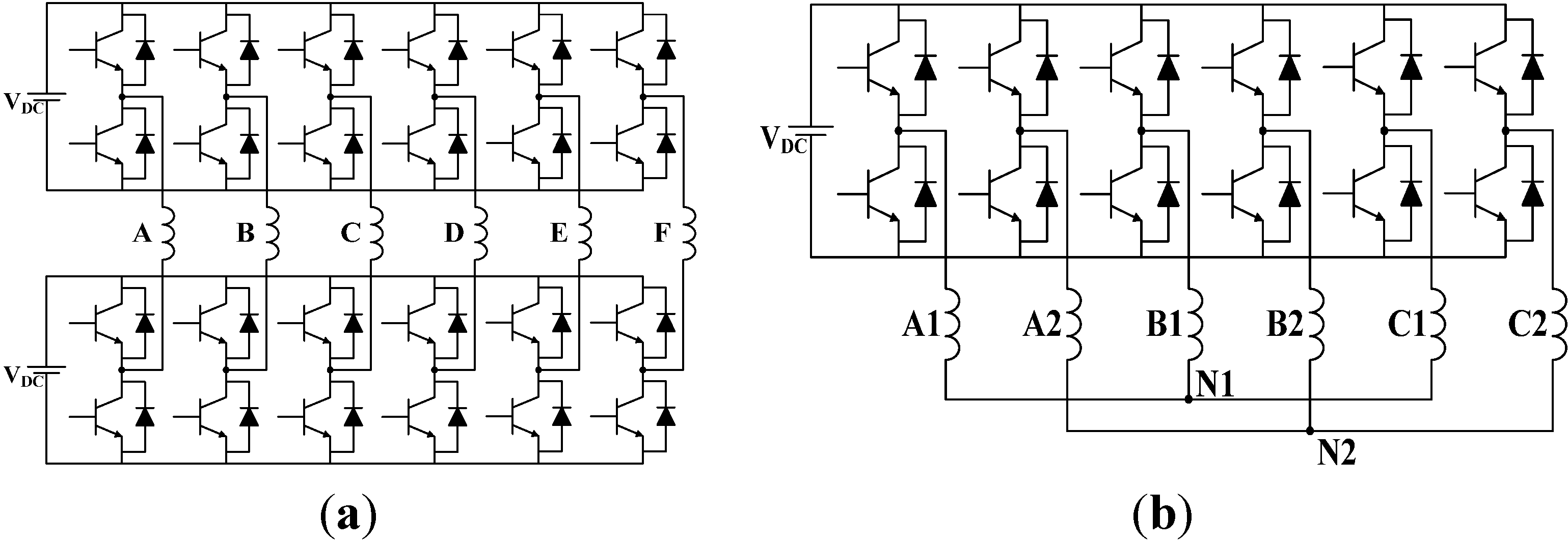
Recently, an increasing interest in open winding AC machines is noticed. The configuration of an inverter for an open winding machine compared with a conventional inverter for wye-connection winding is shown in Figure 1(a) and (b), respectively. The open winding machine benefits a lot from canceling the connection between phase windings and using full bridge converters [17,18]. The open winding machine and its control system make phase-deficiency operation possible. Besides, higher power rating, more active pulse width modulation (PWM) states and new flux weakening techniques are potential advantages. Research on open windings puts more efforts on the safe operation of electrical machines [19,20].
Figure 1. Configurations of inverter for open winding PMSMs and Y-connected winding: (a) Full-bridge-inverters-fed open winding; (b) Half-bridge-inverters-fed Y-connected winding.
Energies 05 03586 g001
Three configurations of fault-tolerant six-phase PMSMs are given and compared, as shown in Figure 2 and Table 1. The windings of a dual three-phase PMSM are made up of two Y-connected windings [21], as shown in Figure 1(b) and Figure 2(a). Despite the advantage of driving by two low-cost general three-phase inverters, the dual three-phase scheme has only two fault-tolerant units and fails to handle continuous and deep winding faults. The configurations in 
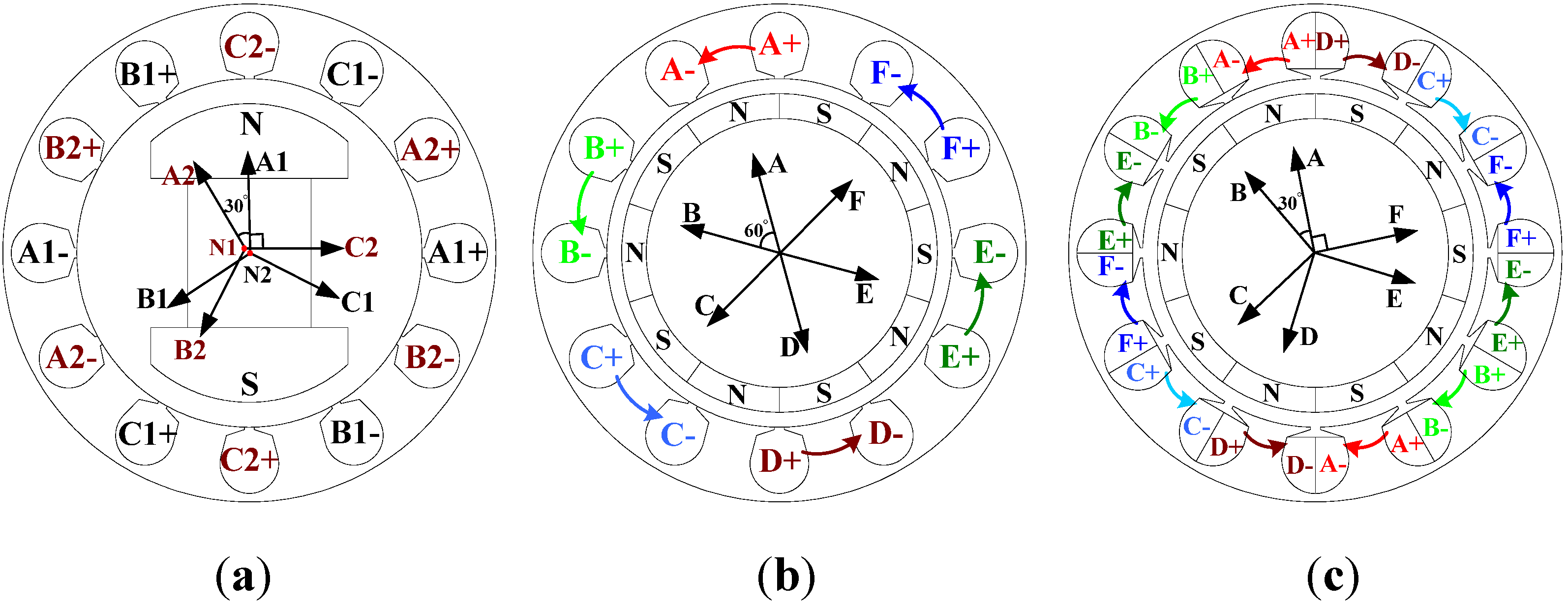
Figure 2(b) and (c) are both supplied with six full-bridge inverters and adopt the open winding concept, allowing to achieve high fault-tolerant capability. On phase-belt level, the former with a phase belt of 60° was called the symmetric six-phase PMSM and the latter with a phase belt of 30° was named asymmetric six-phase PMSM or semi-12-phase PMSM [
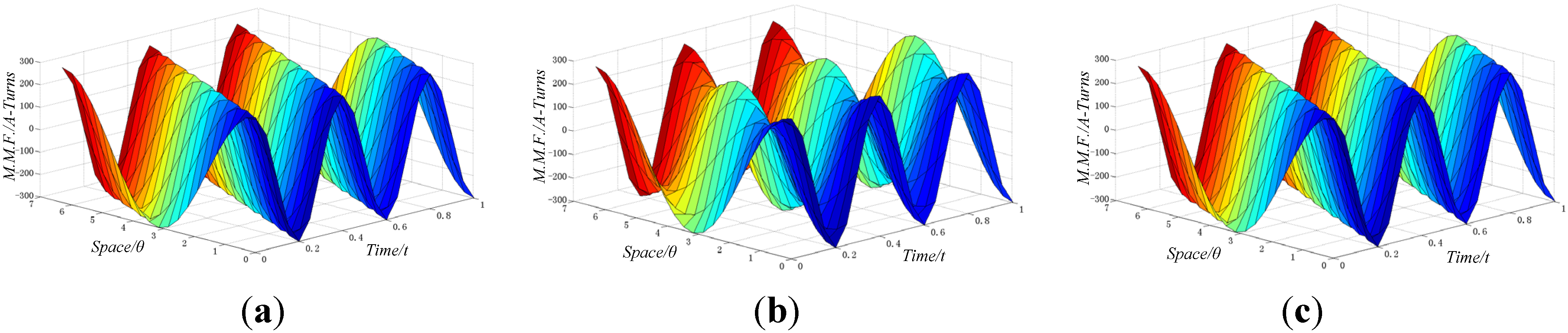
22]. The symmetric-six phase PMSM has a magnetic circuit that is similar to a 60°-phase-belt three-phase PMSM. The MMF harmonic components in the dual three-phase and semi-12-phase PMSM consist of (12k ± 1)th harmonics, while that of the symmetric six-phase scheme consists of (6k ± 1)th harmonics. The harmonic components of MMF and rotor-magnet field interact with each other to produce the torque ripple. The symmetric six-phase scheme has more harmonic components compared to the other two structures, which leads to a large torque ripple. Besides, the symmetric-six phase scheme can’t handle certain four-phase-open-circuited faults in which two opposite phases survive, which is unchallenged for the semi-12-phase scheme.
Figure 2. Configurations of six-phase PMSMs: (a) The dual three-phase PMSM; (b) The symmetric six-phase PMSM; (c) The semi-twelve-phase PMSM.
Energies 05 03586 g002
Table 1. Comparison of three six-phase PMSM configurations.
FeatureDual Three-phaseSymmetric Six-phaseSemi-12-phase
Torque rippleLowHighLow
Winding connectionClose windingOpen windingOpen winding
Fault-tolerant unitTwo 3-phase windingsIndependent phasesIndependent phases
InvertersHalf-bridgeFull-bridgeFull-bridge
PE CostLowSlightly highSlightly high
In this paper, a semi-12-phase outer rotor PMSM which has great advantages of low torque ripple and high fault-tolerant capability is proposed for high-comfort and high-reliability four-wheel-driving electric vehicle applications [23,24]. For four-wheel-driving EVs, the torque ripple of the PMSM is directly associated with the vibration and acoustic noise. The PMSM equipped with fractional slot concentrated winding has a lower torque ripple which implies a lower vibration and acoustic noise, especially at low speeds. This feature makes the machine discussed in this paper quite competitive in four-wheel-driving EV applications.
High iron loss and temperature rise of permanent magnets (PMs) due to excessive magnetomotive force (MMF) harmonic components are the main drawbacks for a PMSM equipped with FSCWs, especially in high-speed operation. In this paper, all-teeth-wound FSCW is employed, and the improved winding disposition changes the winding factor of each harmonic component to suppress air-gap MMF harmonic components.
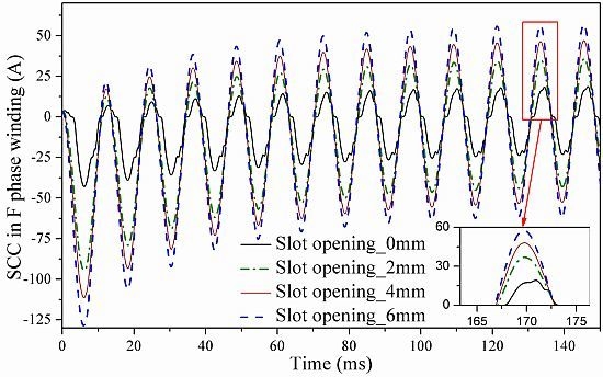
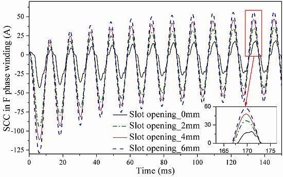
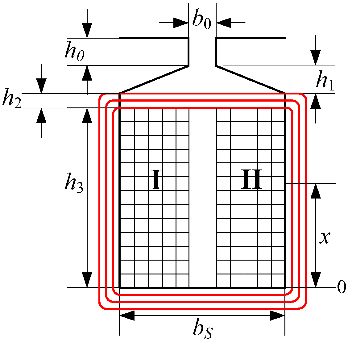
The current induced in the short-circuited coil of a distributed overlapped-winding induction machine can be limited to nearly zero by canceling the flux that passes through the short-circuited coil, which is impossible for a PMSM equipped with FSCWs. Therefore, the only way to limit short-circuit current (SCC) is to have a large leakage inductance. For this purpose, an analytical method that calculates the slot leakage inductance of stators with all-teeth-wound FSCWs is proposed.
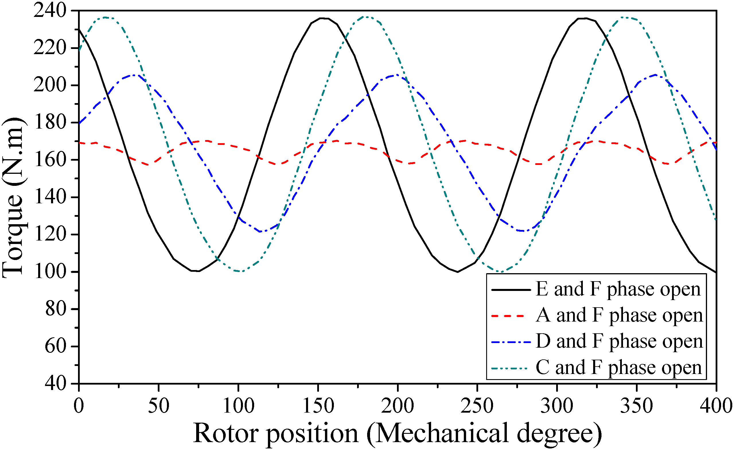
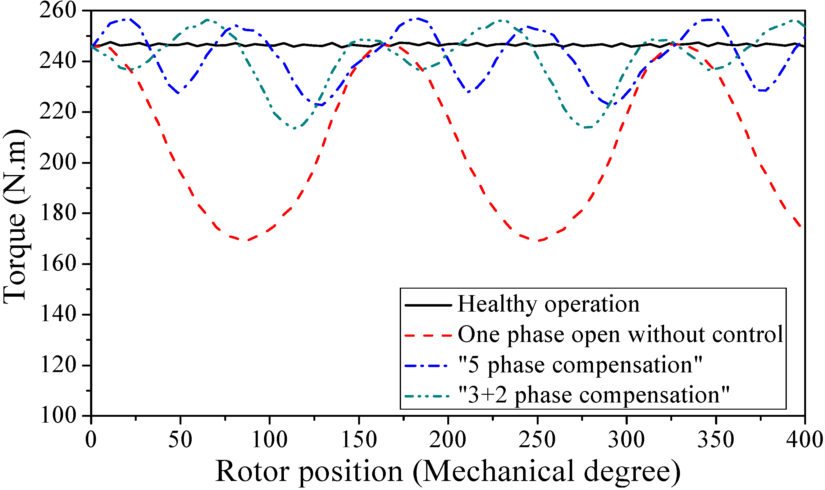
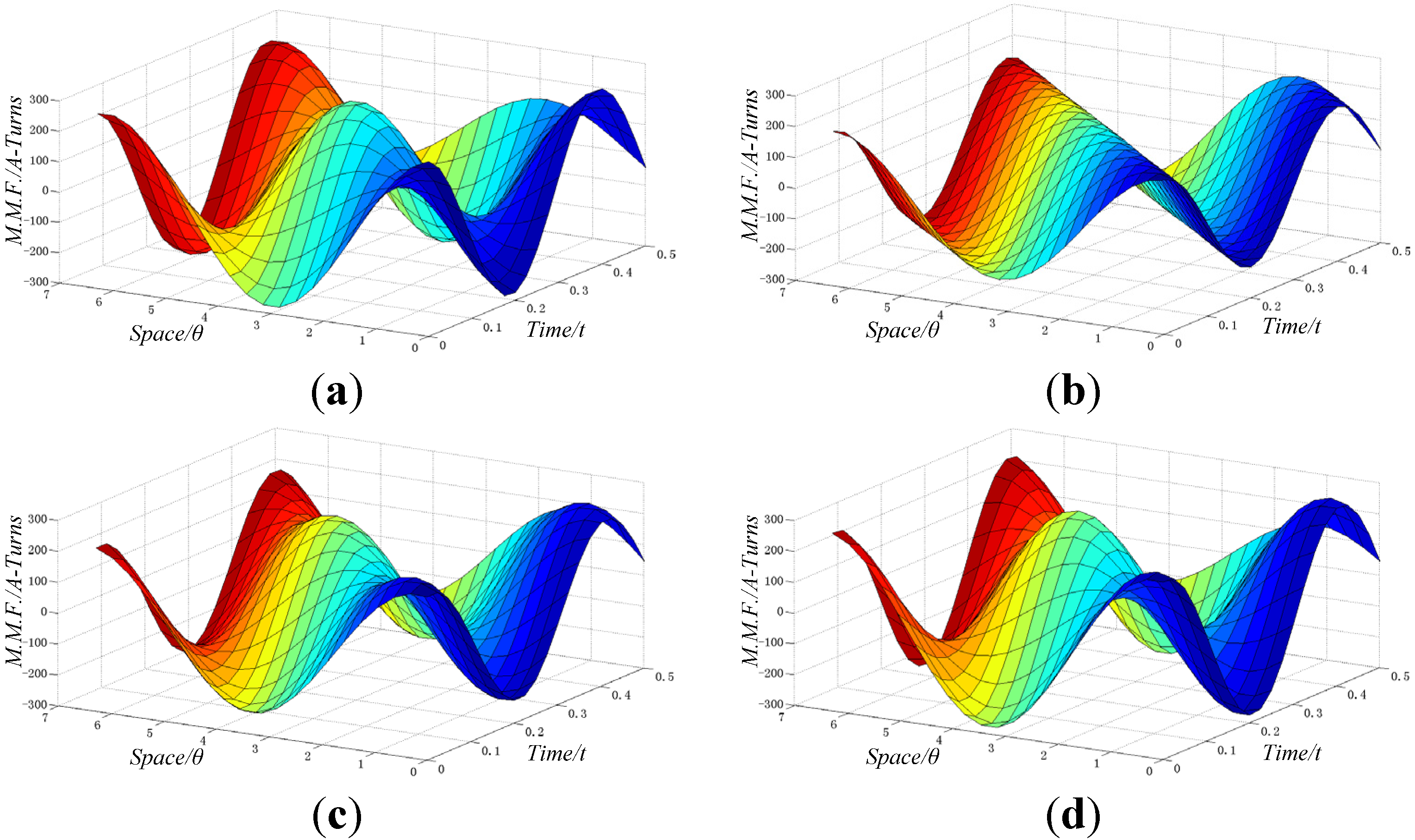
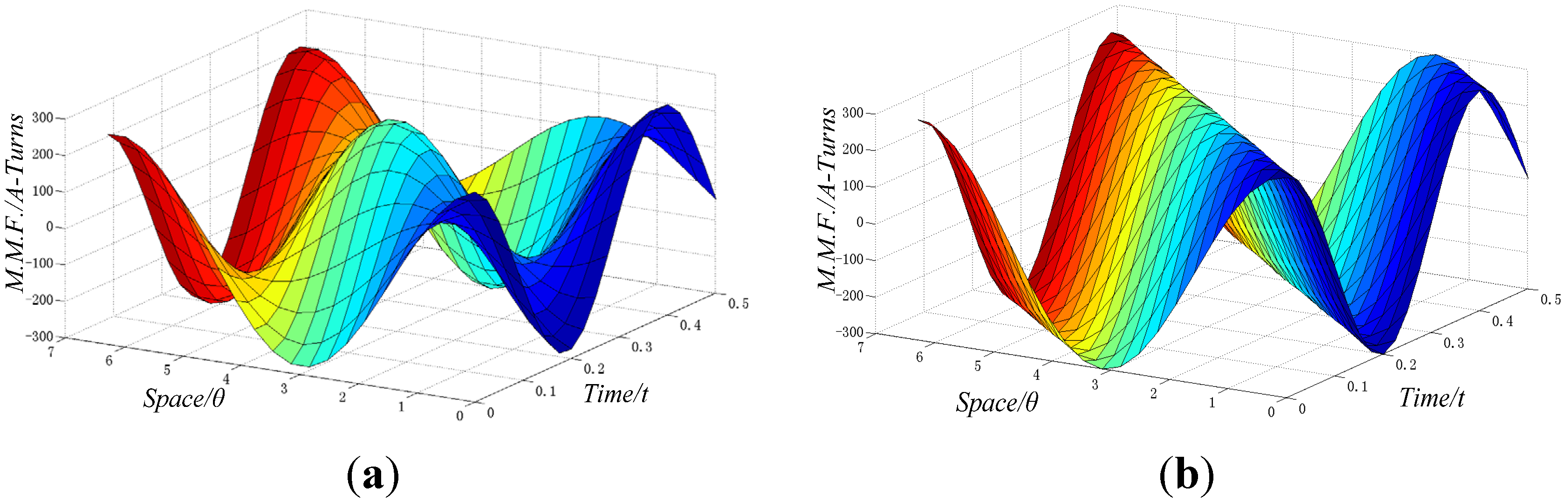
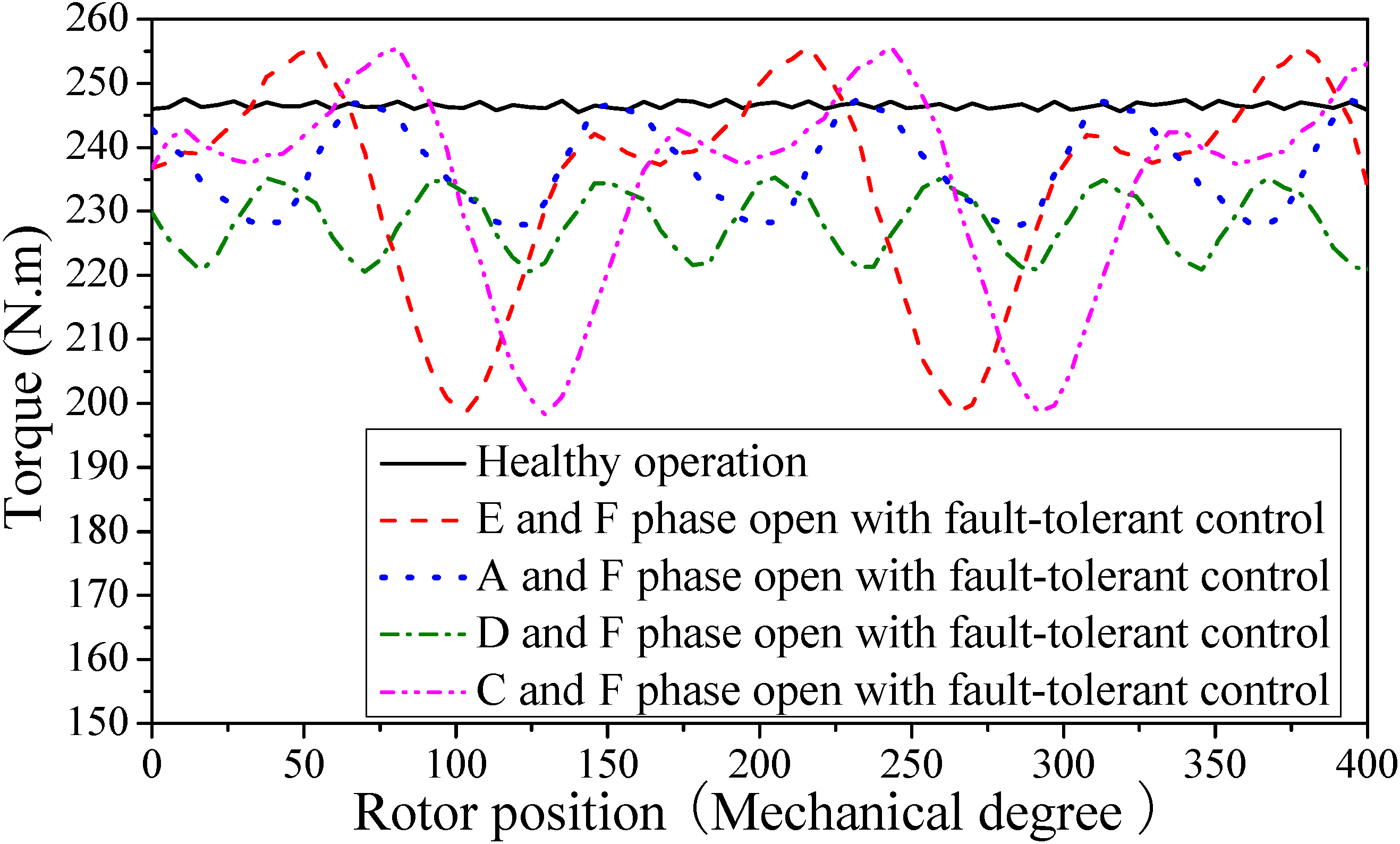
The semi-12-phase PMSM is potentially fault tolerant due to its additional degrees of freedom. The fault-tolerant control strategy that provides the same torque-producing MMF to ensure safe operation is investigated with one-phase and two-phase-open fault based on finite element analysis. The fault-tolerant control strategies in each faulty mode are investigated.

2. Analysis and Suppression of MMF Harmonics

FSCWs, in which slot (Q) and pole number (2p) satisfy 2p = Q ± 2, are employed in motor design in order to maximize the flux linkage and torque density. Besides, the cogging torque is quite low due to the relatively large common multiple of pole and slot number.
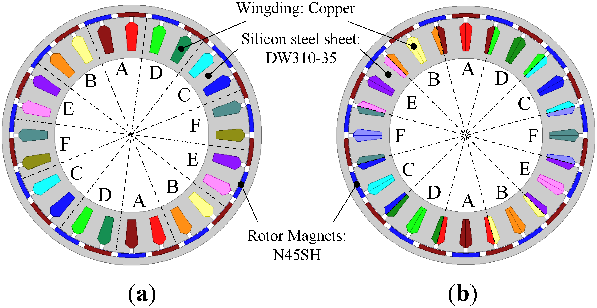
There are two winding patterns for FSCWs. One is all-teeth-wound windings, which means the windings are wound on every tooth, and the other is alternate-teeth-wound windings, which means the windings are wound on every other tooth. The two patterns of winding disposition for a 24-slot/22-pole semi-12-phase PMSM equipped with FSCWs are shown in Figure 3(a) and (b), respectively.
Figure 3. Cross-section diagram of two winding dispositions of a 24-slot/22-pole outer rotor semi-12-phase PMSM equipped with FSCWs: (a) Alternate teeth wound scheme; (b) All teeth wound scheme.
Energies 05 03586 g003
The harmonic analysis of MMF is performed, considering only symmetric systems. Harmonic distribution depends on the stator winding dispositions and the slot/pole combination. For a semi-12-phase PMSM equipped with FSCWs, the (12k ± 1)th (k = 0, 1, 2…) harmonics of MMF are produced in the air-gap when the windings are supplied with a sinusoidal current [22]. For the 24-slot/22-pole PMSM shown in Figure 3(a), the fundamental component of MMF is the 22-pole winding-produced MMF harmonic. Meanwhile, the 2-pole sub-harmonic component which travels at a reverse different speed is particularly high. Thus it induces eddy current both in iron and PMs, which is decided by the amplitude and speed difference. Such a large harmonic content can drastically reduce the motor performance. Specifically, it can reduce the power factor and efficiency, and cause temperature rises in the PMs. Harmonic suppression is urgently needed. As shown in Figure 3(b), all-teeth-wound windings are employed to solve this problem. Such a winding disposition changes the winding factor of each harmonic to achieve the goal of harmonic suppression.
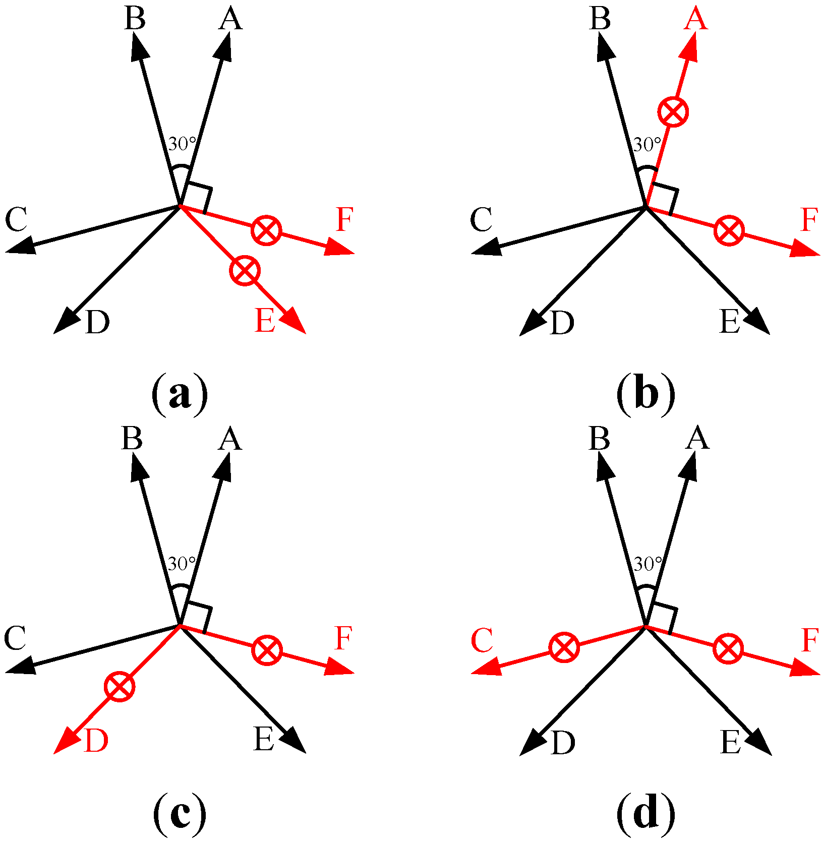
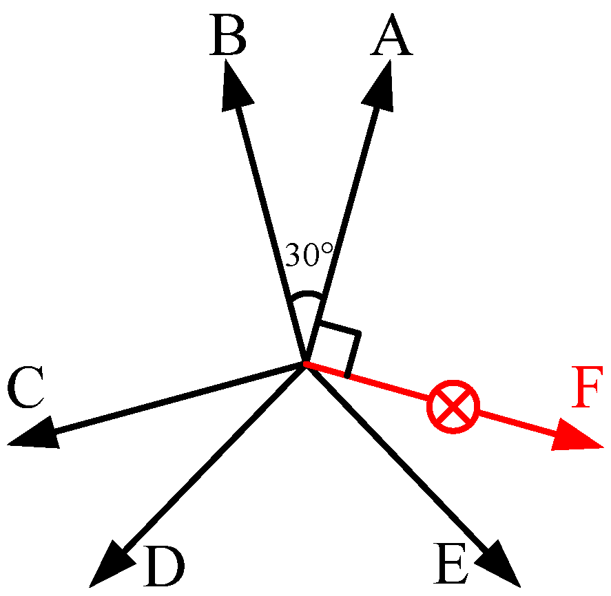
More details are shown in the following analysis. First, we consider the derivation of air-gap MMF. The angle between the two MMF vectors of arbitrary phase is 165 degree rather than zero or 180, as is shown in Figure 4(b). Such a winding disposition changes the winding factor of each harmonics to achieve the goal of harmonic suppression. The (24k ± 1)th (k = 0, 1, 2…) harmonic contents are suppressed, as shown in Table 2.
Figure 4. MMF vector composition of phase A winding: (a) Alternate teeth wound scheme; (b) All teeth wound scheme.
Energies 05 03586 g004
Table 2. Derivation of air-gap MMF for all-teeth-wound windings.
Harmonic OrderCalculation of MMF
1F1cosωt + F1cos(ωt + 165°) = 0.13·2F1cos(ωt + 82.5°)
11F11cos11ωt + F11cos11(ωt + 165°) = −0.99·2F11cos(11ωt + 187.5°)
13F13cos13ωt + F13cos13(ωt + 165°) = 0.99·2F13cos(13ωt − 7.5°)
23F23cos23ωt + F23cos23(ωt + 165°) = −0.13·2F23cos(23ωt + 97.5°)
25F25cos25ωt + F25cos25(ωt + 165°) = 0.13·2F25cos(25ωt − 97.5°)
24k ± 10.13·2F24k±1cos[(24k ± 1)ωt + 82.5·(24k ± 1)°]
12(2k + 1) ± 10.99·2F12(2k+1)±1cos[(12(2k + 1) ± 1)ωt + 82.5·(12(2k + 1) ± 1)°]
The effectiveness of harmonic suppression can be seen in Figure 5 and Figure 6 without considering the effect of rotor PMs. The amplitudes of 1st, 11th and 13th MMF harmonics are close to each other in a 24-slot/22-pole PMSM. However, the magnetic permeance of the 1st harmonic is lower than that of the 11th and 13th harmonics due to stator slotting. Thus, we could see the 1st air-gap flux density harmonic component which has lower amplitude than the 11th and 13th one in Figure 6(a). Besides, the 2-pole sub-harmonic component is prominently decreased by employing all-teeth-wound windings.
For the 24-slot/22-pole scheme, the 11th MMF harmonic is the fundamental component. The eddy-current loss of rotor magnets is determined by the relative velocity (versus the fundamental component) and amplitude of the harmonic. As can be seen in Figure 6, the 1st, 13th, 35th, 37th, etc. are serious harmonics. The rotating speeds of the harmonics are inversely proportional to the order they have. Thus, the 1st harmonic has highest relative velocity with respect to the fundamental component (twelvefold the machine speed), which makes it become the most serious and dangerous harmonic to the eddy-current loss of rotor magnets. While, the relative speed of 13th harmonic component to the fundamental one is less than double machine speed. Thus, the impact of the 13th harmonic component on eddy-current loss is much more alleviative than that of the 1st one. Besides, the 13th harmonic has the same distributed factor with the fundamental component (11th). Thus, it cannot be eliminated. Besides, all the harmonic components in the 24-slot/22-pole machine lead to a large harmonic leakage inductance. On one hand it increases the inductance of the machine which is essential for flux-weakening operation and short-circuit current suppression, and on the other hand it lowers the power factor of the machine.
Figure 5. Air-gap flux density of 24-slot/22-pole PMSM: (a) Alternate teeth wound scheme; (b) All teeth wound scheme.
Energies 05 03586 g005
Figure 6. Air-gap flux density harmonic analysis of 24-slot/22-pole PMSM: (a) Alternate teeth wound scheme; (b) All teeth wound scheme.
Energies 05 03586 g006
In the following a calculation method of harmonic leakage inductance is presented. The relationship between the hth harmonic and main inductance is given by [25]:
Energies 05 03586 i001
where Lh is hth harmonic leakage inductance; Kωh is the hth harmonic winding factor (h = 12k ± 1, k = 0, 1, 2, 3…); Lm is the main inductance. The hth harmonic leakage inductance can be reduced through changing its winding factor. The total harmonic leakage inductance equals to the sum of all harmonic leakage inductances minus the main inductance:
Energies 05 03586 i002
where Ll is total harmonic leakage inductance. ΣS is harmonic leakage coefficient. All-teeth-wound FSCW diminishes the harmonic leakage coefficient and reduce the harmonic leakage inductance. The winding factor is the determinants of harmonic leakage coefficient ΣS:
Kwh = KphKdhKskh
where Kph is the pitch factor; Kdh is the distribution factor; Kskh = 1 is the skewing factor:
Energies 05 03586 i003
where y = 1 is the pitch of FSCW. The slot number per pole per phase is:
Energies 05 03586 i004
Equation (5) can be expressed as:
Energies 05 03586 i005
The distribution factor of FSCW is:
Energies 05 03586 i006
where:
q' = qc = ac + b = 2
Energies 05 03586 i007
The meaning of is 11 poles occupying two slots per phase. The phase belt is 30°. For the PMSM equipped with all-teeth-wound FSCWs shown in Figure 3(b), the winding factor can be written as:
Energies 05 03586 i008
where the two coefficients in Equation (10) are added to take harmonic suppression into account. Finally, the harmonic leakage coefficient is given by:
Energies 05 03586 i009
while for alternate-teeth-windings:
Energies 05 03586 i010
It should be noted that the harmonic leakage coefficient is prominently decreased after applying all-teeth-wound winding. However, the harmonic leakage inductance should still be taken into account due to the comparable value with main inductance. The semi-12-phase machine has been simulated using finite-element method, as shown in Table 3.
Table 3. Results of finite element analysis.
Slot/pole CombinationTorque (N·m)Torque Ripple (%)Iron Loss (W)PM Loss (W)Power FactorEfficiency (%)
24S/22P/AT245.880.51292.5138.610.87094.3
24S/22P/AL245.790.61586.3135.860.91695.6
24S/26P/AT245.990.810112.648.910.93594.4
24S/26P/AL245.920.747109.146.030.94695.0
S—slots, P—poles, AT—alternate teeth wound, AL—all teeth wound, Motor speed—450 rpm.
All of the four configurations compared in Table 3 have a very smooth torque. For the 24-slot/22-pole combination, the iron loss and PM loss of all-teeth-wound machine are 6.7% and 7.1% less than for the alternate-teeth-wound one, respectively. For the 24-slot/26-pole combination, the iron loss and PM loss of all-teeth-wound machine are 3.1% and 5.9% less than the alternate-teeth-wound one, respectively. The efficiencies of the machines equipped with all-teeth-wound FSCWs are higher than that with alternate-teeth-wound FSCWs.
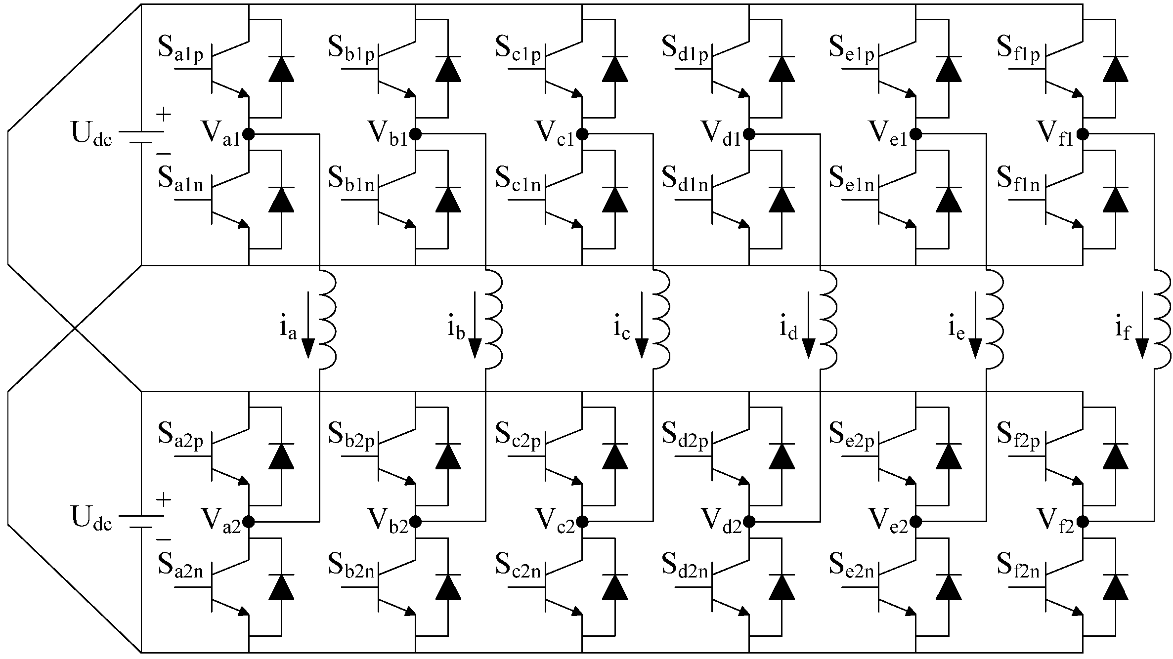
A 24-slot/22-pole all-teeth-wound scheme has been chosen for further study, since it has the highest efficiency among the four schemes. And, an outer-rotor type machine is employed to accommodate wheel-driving electric vehicles. The semi-twelve-phase open-winding PMSM is supplied with a cascaded voltage source convertor which consists of six four-switch full-bridge inverters, as shown in Figure 7. Additionally, the electromagnetic characteristics are shown in Table 4.
Figure 7. Cascaded VSC feeding the semi-twelve-phase open-winding PMSM.
Energies 05 03586 g007
Table 4. Key parameters and dimensions of the 24-slot/22-pole all-teeth-wound scheme.
Parameters/DimensionsUnitsValue
Number of slots/poles24/22
Slots per pole per phase2/11
Stator outer diametermm290
Rotor outer diametermm310
Stack lengthmm50
Material of rotor magnetsN45SH
Pole arc coefficient0.75
Magnet heightmm5
Air-gap thicknessmm0.8
Rated/Peak powerkW12/24
Rated per phase currentArms25
Rated/Maximum back-EMFVpk167/288

3. Winding Terminal Short-Circuit Fault

For winding terminal short-circuit faults, it is hard to cancel the flux that passes through the short-circuited winding for PMSM equipped with FSCWs. Thus, the only way to limit short-circuit current is to possess a large leakage inductance [22].

3.1. Calculation of Slot Leakage Inductance

A significant design parameter of such machines is the phase winding inductance, since it has a prominent impact on the performance, such as SCC, power factor and flux-weakening capability. Furthermore, the main component of the winding inductance is the relatively large slot leakage inductance and harmonic leakage inductance. Since the harmonic leakage flux may cause extra torque ripple and iron loss, it is more convenient to use the slot leakage inductance to limit the SCC. The slot leakage inductance can be easily adjusted by changing the slot shape.
Consider the simplified flat-bottom slot with semi-closed opening shown in Figure 8. The coils in one slot include coil-I as the left coil side and coil-II as the right coil side. For the semi-12-phase PMSM shown in Figure 3(b), there are four slots with different phase conductors and two slots with the same phase conductors in phase A. For the slot with two same phase conductors, the slot leakage inductance is made up of the self-inductance of one left and one right side and the mutual inductance between them.
Figure 8. Simplified stator slot with all-teeth-wound windings.
Energies 05 03586 g008
The specific slot permeance of the left coil side is given by [25]:
Energies 05 03586 i011
The specific slot permeance of the right side is exactly the same as the left side, since they are geometrically symmetrical. So the self-inductance is clearly:
Energies 05 03586 i012
where N1, N2 is the number of series-connected conductors in the left side and right side coil, respectively. leff is stator equivalent length. Assume that the number of turns are equal, then N1 = N2 = N:
LL = LR = L = N2leffps
For 0 < x < h3, the mutual inductance for this portion of the slot is:
Energies 05 03586 i013
where I is the winding rms current.
For the non-conductor portion h0, h1 and h2, the mutual inductance is:
Energies 05 03586 i014
The mutual inductance is:
Energies 05 03586 i015
The slot leakage inductance with two same phase conductors is:
Lslot(S) = 2L ± 2M
While the slot leakage inductance of the phase A coil that shares a slot with other phase coil is:
Lslot(D) = L ± M cosθ
where θ depends on the phase angle difference between winding exciting currents. The signature ± in (19) and (20) are added to differentiate coupling direction of two coils.
The total slot leakage inductance of phase A is:
Lslot(semi−12) = 4Lslot(D) + 2Lslot(S) = 2(L + M cos30°) + 2(LM cos150°) + 2(2L + 2M)
The above expression is simplified as:
Lslot(semi−12) = 8L + 7.464M

3.2. Impact of Slot Leakage Inductance on SCC

In the above derivation, it is necessary to mention that the determinants of slot leakage inductance are the thickness of pole shoe (h0 and h1), slot opening width (b0) and depth of slot (h2, h3). For an outer rotor machine, it is possible to design a deep slot to enlarge the slot leakage.
Assume that phase F is short-circuited. It is worth noticing that a high leakage inductance leads to high SCC controllability and flux-weakening capability while a poor power factor will be the main drawback, so it is natural to consider establishing a balance between the controllability of SCC and the power factor through optimization of the slot dimensions. The 2D finite-element method is employed to study the impact of slot leakage inductance on SCC when slot opening width is 0, 1, 2, 3, 4, 5 and 6 mm, respectively. The 2D simulation results are shown in Figure 9 and Table 5. The SCC decreases with the decrease of the slot opening width due to an increasing slot leakage inductance.
Although the SCC decreases with the increase of the slot leakage inductance, it is not worth limiting the SCC to 1 per unit while a quite low power factor is brought. On the other side, the stator copper loss and negative torque will increase with higher SCC. The scheme with slot opening of 4 mm is recommended, since it has a high power factor and the SCC is less than 2 per unit.
Figure 9. Waveforms of SCC in phase F winding.
Energies 05 03586 g009
Table 5. Performance comparison in short-circuit faulty mode with varying slot opening width.
Slot Opening Width (mm)Slot Leakage Inductance (mH)Torque (N·m)Peak Value of SCC (A)Copper Loss of the Shorted-Circuited Phase Winding (p.u.)Power Factor
00.057164.5720.40.670.747
10.049222.6632.91.730.841
20.033237.2339.32.470.899
30.027244.0445.03.240.932
40.023247.6749.63.920.945
50.021249.8053.54.580.956
60.018251.1158.75.510.966
The rated peak value of phase winding current for the designed semi-12-phase PMSM is 25 A (1 per unit); Motor speed is 450 rpm.

4. Phase-Deficient Operation and Fault-Tolerant Control

Winding open circuits are a common fault in AC machines. Several possible causes are winding breaking due to mechanical or electromagnetic force, sealing-off due to long-running overheat operation, utilization of corrosive flux, etc. Multiphase machines are potentially fault-tolerant due to their additional degrees of freedom. For the sake of providing the same torque-producing MMF to ensure safe operation, it is feasible to regulate the amplitude and phase angle of exciting current in the remaining phases. Additionally, in a multi-dimension system, the exciting currents are not unique. Thus, there are various fault-tolerant control strategies. In this section, the states of one phase open and two phases open are fully discussed.

4.1. “5 Phases Compensation” for One-Phase-Open Fault

For one-phase-open fault, there is only one case, as shown in Figure 10.
Figure 10. Schematic diagram of one-phase-open fault.
Energies 05 03586 g010
The MMF produced by the lost phase can be compensated by regulating the amplitude and phase angle of the exciting current in the remaining five phases, which is called “5 phases compensation”.
Under healthy conditions, the stator winding MMF F6 are given as follows, considering only the 22-pole fundamental component:
Energies 05 03586 i016
where N is the number of turns per phase, Im is the peak value of exciting current, ω is the angular frequency of current, θ is space angle. Equation (23) can be written as:
Energies 05 03586 i017
Assume that phase F is open. The rotating MMF with one-phase open can be calculated by:
Energies 05 03586 i018
where ia, ib, ic, id, ie are exciting currents of phases A, B, C, D, E, respectively. Equation (25) can be written as:
Energies 05 03586 i019
The following equations can be obtained based on Equation (24) and Equation (26):
Energies 05 03586 i020
In a multi-dimension system, the exciting currents are not unique. We have five unknown exciting current and two solution equations in Equation (27). Three more solution equations are required for solving the currents in the remaining phases:
(1)
Set the sum of the remaining phase currents to zero;
(2)
Assume that the amplitudes of all exciting currents in the remaining phases are the same;
(3)
Minimize the amplitudes of exciting currents.
Finally, the currents in the remaining phases can be calculated as follows:
Energies 05 03586 i021
To ensure the effectiveness of the above derivation, the waveforms of MMF distribution in time and space are drawn in Figure 11 by Matlab. It can be seen that the amplitude of MMF is decreased and waveform distorted in faulty mode. After applying the new set of currents, it is quite similar to the healthy condition.
Figure 11. MMF distribution in time and space; (a) Healthy operation; (b) F phase open; (c) Fault-tolerant control.
Energies 05 03586 g011

4.2. “3 + 2 Phases Compensation” for One-Phase-Open Fault

For one-phase-open fault, three symmetric phases can be found in the remaining five phases (phases A, C and E in Figure 10). The three symmetric phases produce half of the output torque. And, the exciting current of the asymmetric two phases (phases B and D in Figure 10) are regulated to compensate the lost phase. This fault-tolerant control strategy is named “3 + 2 compensation” in this paper.
In healthy condition, the MMF produced by phases B, D and F is:
Energies 05 03586 i022
The MMF produced by phases B and D in phase F open faulty mode is:
Energies 05 03586 i023
The following equations can be obtained based on (29) and (30):
Energies 05 03586 i024
The exciting currents in phases B and D can be calculated as follows:
Energies 05 03586 i025
meanwhile:
Energies 05 03586 i026
The performances of “5 phases compensation” and “3 + 2 phases compensation” are compared based on finite element analysis, as shown in Figure 12 and Table 6.
The “3 + 2 phases compensation” has more iron loss, but less PM loss and copper loss compared with “5 phases compensation”. Overall, the efficiency of the machine applying “3 + 2 phases compensation” strategy is higher. Therefore, “3 + 2 phases compensation” strategy is more suitable for high-efficiency electric vehicle applications. From the aspect of winding maximum current, the “3 + 2 phases compensation” is higher than “5 phases compensation”, but this will not increase the current rating of power switches, since this is within the range of more-phase-fault operating states.
Figure 12. Torque behavior for one-phase-open fault.
Energies 05 03586 g012
Table 6. Performance Comparison of Different Fault-Tolerant Control Strategies.
StrategyTorque (N.m)Torque Ripple (%)Iron Loss (W)PM Loss (W)Copper Loss (W)Efficiency (%)
Healthy operation245.790.6186.3135.86382.5095.6
F phase open operation203.0519.298.4234.05318.6095.4
5 phases compensation237.797.1097.6965.00660.9692.6
“3 + 2” phases compensation237.458.8998.2761.30573.7593.4

4.3. Two-Phase-Open Fault

For two-phase-open fault, there are four cases, as shown in Figure 13.
Figure 13. Four cases of two-phase-open fault; (a) Adjacent, apart by 30°; (b) Adjacent, apart by 90°; (c) Nonadjacent, apart by 120°; (d) Nonadjacent, apart by 150°.
Energies 05 03586 g013
The waveforms of MMF distribution in time and space are drawn to observe changes in faulty modes, as shown in Figure 14.
Figure 14. The MMF distributions in time and space; (a) Adjacent, apart by 30°; (b) Adjacent, apart by 90°; (c) Nonadjacent, apart by 120°; (d) Nonadjacent, apart by 150°.
Energies 05 03586 g014
The four faulty cases of two-phase-open fault are compared based on finite-element method. The average torque drops a lot due to the increased number of lost phases, as shown in Figure 15 and Table 7. The torque ripples in case (a), (c) and (d) are evidently high while that in case (b) is prominently low due to its slightly distorted MMF in time and space, as shown in Figure 14(b).
Figure 15. Torque behavior for two-phase-open fault.
Energies 05 03586 g015
Table 7. Motor Performance in Two-Phase-Open Fault.
CasesTorque (N·m)Torque Ripple (%)Iron Loss (W)PM Loss (W)Copper Loss (W)Efficiency (%)
(a)163.4942.75106.2031.82255.094.9
(b)163.065.1086.1129.24255.095.2
(c)163.4626.8495.8829.78255.095.0
(d)163.9743.70106.6731.79255.094.9
Case (a)—Adjacent, apart by 30°; Case (b)—Adjacent, apart by 90°; Case (c)—Nonadjacent, apart by 120°; Case (d)—Nonadjacent, apart by 150°.
In two-phase-open faulty mode, more MMF harmonic components are produced by the asymmetric phase windings compared with healthy operation, which induce eddy currents in iron core and PMs. The principles of fault-tolerant control in open-circuit fault are:
(1)
Try to keep three symmetric phases unchanged (“phases A, C and E” or “phases B, D and F”);
(2)
Take three symmetric phases as a fault-tolerant unit. When one phase is lost, the other two phases are used to compensate it if possible;
(3)
In some specific cases, the waveform of MMF is not distorted. Only increase the amplitude of the currents in the remaining phases.
For case (a) in Figure 13, two adjacent phases apart by 30° are lost. Assume that the adjacent phases E and F are lost. The MMF produced by phase E can be compensated by phases A and C. Similarly, the MMF produced by phase F can be compensated by phases B and D. The exciting current in the remaining phases can be obtained as follows:
Energies 05 03586 i027
To ensure the effectiveness of the above derivation, the waveforms of MMF distribution in time and space are drawn, as shown in Figure 16.
Figure 16. The MMF distribution in time and space; (a) Phase E and F open; (b) Fault-tolerant control.
Energies 05 03586 g016
For case (b) in Figure 13, two adjacent phases apart by 90° are open circuited. The fault-tolerant control strategy is simply increasing the amplitude of the currents in the remaining four phases:
Energies 05 03586 i028
For case (c) in Figure 13, two nonadjacent phases apart by 120° are lost. Assume that phases D and F are lost. We can still have the symmetric phases A, C and E while the phases B, D and F are cut off. The main drawback of this fault-control strategy is that the exciting currents in phases A, C and E are double:
Energies 05 03586 i029
For case (d) in Figure 13, two adjacent phases apart by 150° are lost. Assume that phases C and E are lost. The MMF produced by phase C can be compensated by phases A and F. Similarly, the MMF produced by phase E can be compensated by phases B and D. The exciting current in the remaining phases can be obtained as follows:
Energies 05 03586 i030
The above control strategies corresponding to the four two-phase-open fault cases are checked using finite element analysis. The results are shown in Figure 17 and Table 8. The per unit values of Table 8 are shown in Table 9.
Figure 17. Torque behaviors for healthy operation and two-phase-open fault-tolerant control.
Energies 05 03586 g017
Table 8. Motor performance in fault-tolerant control modes based on FEA.
CaseTorque (N·m)Torque Ripple (%)Iron Loss (W)PM Loss (W)Copper Loss (W)Efficiency(%)
Healthy operation245.790.6186.3135.86382.595.6
(a)235.0112.26100.4568.71765.091.6
(b)237.154.1599.7661.14573.7593.4
(c)228.413.2698.1667.13765.091.4
(d)232.9112.3499.6869.38765.091.5
Case (a)—Adjacent, apart by 30°; Case (b)—Adjacent, apart by 90°; Case (c)—Nonadjacent, apart by 120°; Case (d)—Nonadjacent, apart by 150°.
Table 9. performance comparison in fault-tolerant control modes using per unit value.
CaseTorque (p. u.)Torque Ripple (p. u.)Iron Loss (p. u.)PM Loss (p. u.)Copper Loss (p. u.)Efficiency (p. u.)
Healthy operation1.01.01.01.01.01.0
(a)0.9620.101.1641.9162.00.96
(b)0.976.801.1561.7051.50.98
(c)0.935.341.1371.8722.00.96
(d)0.9520.231.1551.9352.00.96
Case (a)—Adjacent, apart by 30°; Case (b)—Adjacent, apart by 90°; Case (c)—Nonadjacent, apart by 120°; Case (d)—Nonadjacent, apart by 150°.
It can be seen from Table 8 and Table 9 that with the usage of fault-tolerant control strategies, the average torques of the four cases range from 0.93 to 0.97 p.u., with case (b) being the highest; the torque ripple of cases (b) and (c) are much lower than cases (a) and (d); the iron losses are from 1.1 to 1.2 p.u.; the PM losses are from 1.7 to 2.0 p.u.; and the copper losses are from 1.5 to 2.0 p.u., which means the fault-tolerant operation at different faulty cases are quite acceptable, with some sacrifice of efficiency and torque ripple.

5. Conclusions

(1)
A semi-12-phase PMSM equipped with FSCWs and open windings is recommended for electric vehicle application, with the advantages of high fault-tolerant ability and high operating performance.
(2)
The all-teeth-wound FSCW can suppress (24k ± 1)th harmonic components, so it has less harmonic leakage inductance, iron loss and PM loss, compared with the alternate-teeth-wound FSCW.
(3)
The calculation method of the slot leakage inductance of FSCW is deduced, which is different from traditional double-layer windings. The SCC in winding terminal short circuit fault is limited by designing a suitable slot leakage inductance, considering the balance of SCC and power factor.
(4)
For one-phase-open fault, the “5 phases compensation” and “3 + 2 phases compensation” schemes are discussed and compared. The “3 + 2 phases compensation” is recommended for the advantage of higher efficiency.
(5)
The control strategies of the four cases of two-phase-open fault are discussed. For every case, the average torque can be adjusted to acceptable range, with some sacrifice of efficiency and torque ripple.

Acknowledgments

The authors would like to appreciate the help of Thomas A. Lipo from Wisconsin Electrical Machines and Power Electronics Consortium (WEMPEC), for his advice on the original investigation. This work was supported in part by National Natural Science Foundation of China under Project 51077026, in part by the 863 Plan of China under Project 2011AA11A261, and in part by the Fundamental Research Funds for the Central Universities (Grant No. HIT.BRET1.2010013).

References

  1. El-Refaie, A.M. Fault-tolerant permanent magnet machines: A review. IET Electr. Power Appl. 2011, 5, 59–74. [Google Scholar] [CrossRef]
  2. Bianchi, N.; Bolognani, S.; Dai Pre, M. Strategies for the fault-tolerant current control of a five-phase permanent-magnet motor. IEEE Trans. Ind. Appl. 2007, 43, 2528–2534. [Google Scholar]
  3. Sayed-Ahmed, A.; Mirafzal, B.; Demerdash, N.A.O. Fault-tolerant technique for δ-connected AC motor drives. IEEE Trans. Energy Convers. 2011, 26, 646–653. [Google Scholar] [CrossRef]
  4. Dwari, S.; Parsa, L. Fault-tolerant control of five-phase permanent-magnet motors with trapezoidal back EMF. IEEE Trans. Ind. Electron. 2011, 58, 476–485. [Google Scholar] [CrossRef]
  5. Zheng, P.; Sui, Y.; Zhao, J.; Tong, C.; Lipo, T.A.; Wang, A. Investigation of a novel five-phase modular permanent-magnet in-wheel motor. IEEE Trans. Magn. 2011, 47, 4084–4087. [Google Scholar] [CrossRef]
  6. Merow, B.C.; Jack, A.G.; Atkinson, D.J.; Green, S.R.; Atkinson, G.J.; King, A.; Green, B. Design and testing of a four-phase fault-tolerant permanent-magnet machine for an engine fuel pump. IEEE Trans. Energy Convers. 2004, 19, 671–677. [Google Scholar] [CrossRef]
  7. Atkinson, G.J.; Merow, B.C.; Jack, A.G.; Sangha, P.; Benarous, M. The design of fault tolerant machines for aerospace application. In Proceedings of the 2005 IEEE International Conference on Electric Machines and Drives, San Antonio, TX, USA, 15 May 2005; pp. 1863–1869.
  8. Barcaro, M.; Bianchi, N.; Magnussen, F. Six-phase supply feasibility using a pm fractional-slot dual winding machine. IEEE Trans. Ind. Appl. 2011, 47, 2042–2050. [Google Scholar] [CrossRef]
  9. Alberti, L.; Bianchi, N. Experimental tests of dual three-phase induction motor under faulty operating condition. IEEE Trans. Ind. Electron. 2012, 59, 2041–2048. [Google Scholar] [CrossRef]
  10. Ishak, D.; Zhu, Z.Q.; Howe, D. Permanent-magnet brushless machines with unequal tooth widths and similar slot and pole numbers. IEEE Trans. Ind. Appl. 2005, 41, 584–590. [Google Scholar] [CrossRef]
  11. Tangudu, J.K.; Jahns, T.M.; Bobn, T.P. Design, analysis and loss minimization of a fractional-slot concentrated winding IPM machine for traction applications. In Proceedings of the 2011 IEEE Energy Conversion Congress and Exposition (ECCE), Phoenix, AZ, USA, 17–22 September 2011; pp. 2236–2243.
  12. El-Refaie, A.M.; Jahns, T.M.; Novotny, D.W. Analysis of surface permanent magnet machines with fractional-slot concentrated windings. IEEE Trans. Energy Convers. 2006, 21, 34–43. [Google Scholar] [CrossRef]
  13. Shah, M.R.; El-Refaie, A.M. End effects in multiphase fractional slot concentrated-winding surface permanent magnet synchronous machines. IEEE Trans. Energy Convers. 2010, 25, 1001–1009. [Google Scholar] [CrossRef]
  14. Mecrow, B.C.; Jack, A.G.; Atkinson, D.J.; Green, S.R.; Atkinson, G.J.; King, A.; Green, B. Design and testing of a four-phase fault-tolerant permanent-magnet machine for an engine fuel pump. IEEE Trans. Energy Convers. 2004, 19, 671–678. [Google Scholar] [CrossRef]
  15. Liu, H.; Zhu, Z.Q.; Mohamed, E.; Fu, Y.; Qi, X. Flux-weakening control of nonsalient pole pmsm having large winding inductance, accounting for resistive voltage drop and inverter nonlinearities. IEEE Trans. Power Electron. 2012, 27, 942–952. [Google Scholar] [CrossRef]
  16. Seok-Hee, Han.; Soong, W.L.; Jahns, T.M.; Guven, M.K.; Illindala, M.S. Reducing harmonic eddy-current losses in the stator teeth of interior permanent magnet synchronous machines during flux weakening. IEEE Trans. Energy Convers. 2010, 25, 441–449. [Google Scholar] [CrossRef]
  17. Wang, Y.; Lipo, T.A.; Pan, D. Robust Operation of Double-Output AC Machine Drive. In Proceedings of the 2011 IEEE 8th International Conference on Power Electronics and ECCE Asia, Jeju, Korea, 30 May–3 June 2011; pp. 140–144.
  18. Wang, Y.; Lipo, T.A.; Pan, D. Half-Controlled-Converter-Fed Open-Winding Permanent Magnet Synchronous Generator for Wind Applications. In Proceedings of the 14th International Power Electronics and Motion Control Conference, Ohrid, Republic of Macedonia, 6–8 September 2010; pp. 123–126.
  19. Kawabata, Y.; Nasu, M.; Nomoto, T.; Ejiogu, E.C.; Kawabata, T. High-efficiency and low acoustic noise drive system using open-winding AC motor and two space-vector-modulated inverters. IEEE Trans. Ind. Electron. 2002, 49, 783–789. [Google Scholar] [CrossRef]
  20. Kwak, M.-S.; Sul, S.-K. Control of an open-winding machine in a grid-connected distributed generation system. IEEE Trans. Ind. Appl. 2008, 44, 1259–1267. [Google Scholar] [CrossRef]
  21. Barcaro, M.; Bianchi, N.; Magnussen, F. Analysis and Tests of a Dual Three-Phase 12-Slot 10-Pole Permanent Magnet Motor. In Proceedings of the 2009 IEEE Energy Conversion Congress and Exposition (ECCE), San Jose, CA, USA, 20–24 September 2009; pp. 3587–3594.
  22. Klingshim, E.A. High phase order induction motors—Parts I and II. IEEE Trans. Power Appar. Syst. 1983, 102, 47–59. [Google Scholar] [CrossRef]
  23. Chen, Q.; Liu, G.; Gong, W.; Zhao, W. A new fault-tolerant permanent-magnet machine for electric vehicle applications. IEEE Trans. Magn. 2011, 47, 4183–4186. [Google Scholar] [CrossRef]
  24. Liu, G.; Gong, W.; Chen, Q.; Jian, L.; Shen, Y.; Zhao, W. Design and analysis of new fault-tolerant permanent magnet motors for four-wheel-driving electric vehicles. J. Appl. Phys. 2012, 111, 07E713. [Google Scholar]
  25. Lipo, T.A. Introduction to AC Machine Design, 3rd ed.; Wisconsin Power Electronics Research Center, University of Wisconsin: Madison, WI, USA, 2007; pp. 157–174. [Google Scholar]

