1. Introduction
A battery is an energy storage device that can convert the chemical energy of its material into electrical energy. Lithium-ion (Li-ion) batteries were first introduced in 1976 [
1], and subsequently commercialized in cell phones and laptops by the Sony Corporation in 1991 [
2]. Li-ion batteries are usually composed of a carbon-made anode, a lithium ion conducting material electrolyte, and a cathode. There are a wide range of commercial cathode materials including LiCoO
2 and LiFePO
4, each of which has its own advantages and disadvantages. The chemical reactions occurring in a LiFePO
4 battery during charge and discharge are:
Li-ion batteries were first employed in consumer electronics; however, at the onset of 21st century, due to their advantages such as high energy density, low weight, low self-discharge and long life, they began to dominate energy storage in other fields as well. Other recent applications of Li-ion batteries include electric and hybrid electric vehicles, alternative energy systems such as wind and solar energy, and stationary energy storage. According to a recent study by [
3], Li-ion batteries have been the dominant battery technology in electric and hybrid electric vehicles for over thirty years. They are projected to continue this dominance in transportation and other sectors.
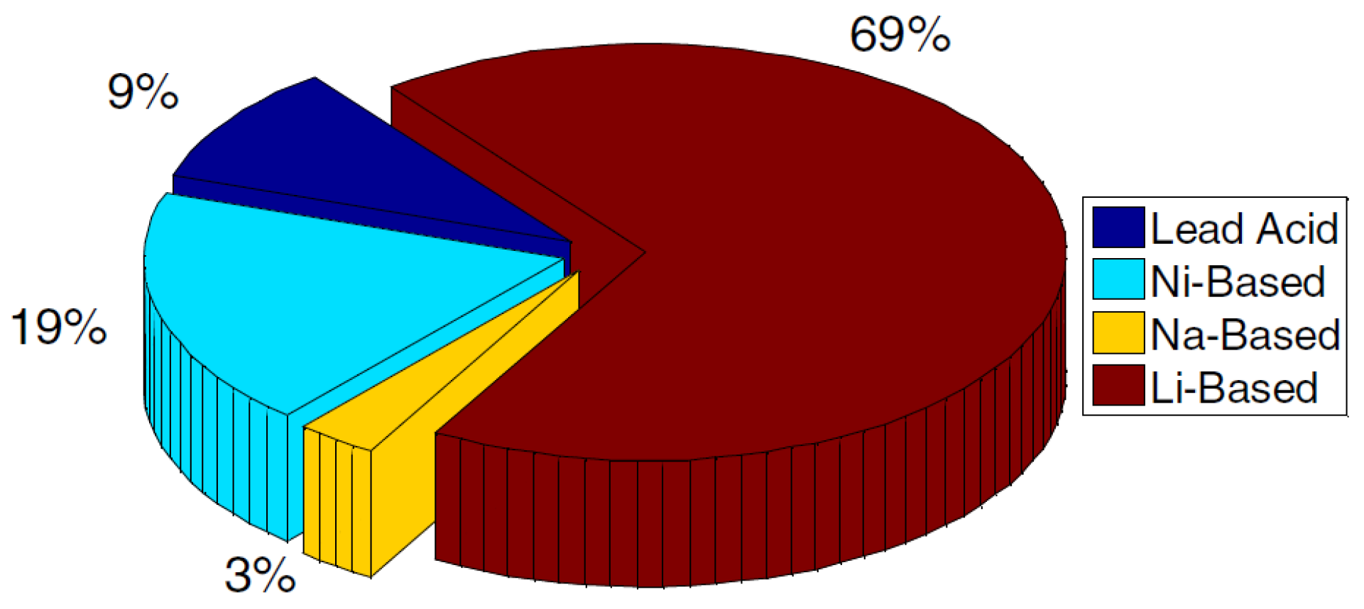
Figure 1 shows the distribution of different energy storage technologies in electric and hybrid electric vehicles.
In order to gain an insight about battery characteristics and investigate its performance, different tests need to be performed. These tests can be categorized as characterization, lifetime, reliability, and abuse tolerance tests [
4]. Galvanostatic intermittent titration technique (GITT) [
5], potentiostatic intermittent titration technique (PITT) [
5], cyclic voltammetry (CV) [
6], and impedance spectroscopy [
6] are some of the commonly used characterization tests. Although these tests provide very useful detailed information about batteries, they typically address individual battery cell characteristics and require advanced and expensive test apparatuses. In order to overcome these issues, a number of tests have been devised to characterize battery cells and packs for transportation applications. A summary of the main international battery test standards is given in [
4,
7]. Although these tests are mainly designed for transportation applications, a majority of them, such as capacity and hybrid pulse power characterization (HPPC) tests [
8], can be used for other Li-ion battery applications as well.
Figure 1.
Distribution of different battery technologies in the transportation sector during the last 30 years [
3].
Figure 1.
Distribution of different battery technologies in the transportation sector during the last 30 years [
3].
Mathematical modeling is used for battery performance analysis and prediction, design optimization, and management system design. There are numerous works in the literature on modeling Li-ion batteries. Doyle
et al. [
9] pioneered electrochemical battery modeling. These models predict the battery performance under different operating conditions and also provide insight into internal battery phenomena. Since Doyle
et al.’s seminal work [
9], different research groups have worked on model order reduction for these electrochemical models with the goal of easing the computational effort [
10,
11]. Although successful, the time-consuming parameter identification process is still a major drawback for these models. On the other hand, equivalent-circuit models, in spite of their limited prediction capability, have been employed extensively due to their efficient online implementation and low computational burden. One of the most commonly-used equivalent-circuit models is the improved Thevenin circuit model proposed by [
12]. Furthermore, Hu
et al. [
13] introduced and compared 12 common battery models for online implementation. In addition to capturing battery dynamics sufficiently for different operating conditions, it is also very easy to identify equivalent-circuit model parameters. There are different methods to identify model parameters. Some of the aforementioned characterization tests such as HPPC can be used for this purpose.
One of the crucial components of a Li-ion battery is its battery management system (BMS). The most trivial task of a BMS is gathering and monitoring information about the battery operating conditions, namely, voltage, current, and temperature. For high voltage and current applications, multiple battery cells need to be connected together, in series and/or parallel, in order to meet the application requirements. In multiple battery configurations, balancing the battery cells is another responsibility of the BMS. More importantly, the BMS should be able to maintain a safe and reliable operation for the battery by controlling its operating voltage, current, and temperature. Finally, based on the battery measureable signals, and typically a battery model, the BMS needs to be able to estimate unmeasurable battery states such as state of charge (SOC) and state of health (SOH). In summary, BMS functionalities include measurement and monitoring, cell balancing, thermal and electrical protection, and state estimation. These functionalities are discussed in more detail below.
Measurement is undoubtedly one of the most important responsibilities of a BMS. Accurate voltage, current and temperature measurements are needed from battery characterization tests to BMS design. There are strict requirements for the accuracy and resolution of voltage and current sensors for Li-ion BMSs. Lu
et al. [
14] reviewed some of voltage measurement methods currently implemented in BMSs.
Battery packs comprised of numerous cells require special attention from BMSs. Due to manufacturing variances, even matching battery cells have different internal characteristics. These differences cause the cells to charge and discharge at unequal rates. For that reason, the voltage across an entire series string of cells does not necessarily have a proportional voltage across each individual cell in that string. For example, a battery charger that only monitors the pack voltage will not fully charge certain cells and will subject other cells to overcharging. These issues can decrease the pack cycle life, cause a large loss in pack capacity over time, and result in safety hazards. To counteract these issues, a technique called cell balancing or charge equalization can be employed. This technique is implemented in a variety of ways; however, the concept for each method is similar. A balancing circuit maintains a uniform charge level among different cells by either dissipating excess energy from fully charged cells or by moving that excess energy to cells that are not fully charged.
Li-ion batteries have a typical operating temperature range of −20 °C to 55 °C for discharge and 0 °C to 45 °C for charging [
15]. Temperature distribution across a battery pack is affected by numerous factors such as environmental variations, the physical structure of the battery pack, and charge and discharge cycles. The physical structure of the battery pack can be optimized in the design stage to guarantee proper heat dissipation. At the design stage, high fidelity three-dimensional (3D) models [
16] are usually employed to develop an optimal structure. On the other hand, the environment and the battery current profile act as disturbances to the temperature distribution inside the pack. Despite these factors, the temperature inside the battery pack, as well as individual cell temperatures, should be maintained in prescribed ranges in order to ensure safe and efficient battery operation. It is graphically demonstrated in [
15] that temperatures that are to low and too high can result in safety hazards and/or battery performance degradation. Therefore, a proper thermal management system is of great importance. As mentioned earlier, the BMS is responsible for thermal management in Li-ion batteries to guarantee their safety, efficiency and prolonged life.
One of the most important BMS functionalities for Li-ion batteries is protection against operating beyond safe voltage and current limits. Battery manufacturers specify low and high voltage and current limits for each battery chemistry. As described in [
17], violating these limits can have a wide range of undesirable effects from minor damage to the complete destruction of a battery to fire and explosion. Therefore, in order to increase the battery lifetime and ensure a safe and reliable operation, individual voltage and current values should be monitored constantly during its operation. As soon as any battery limit is approached, the BMS should take a corrective action in order to protect the battery. The BMS reaction to any of these phenomena can be in the form of interrupting the current or limiting it to a safe value. Recently, researchers are trying to develop more advanced BMSs that are capable of determining less conservative current and voltage thresholds [
11]. These works focus on electrochemical battery models in order to develop algorithms to extract maximum energy while ensuring a safe operation.
State estimation mainly involves SOC and SOH estimation. The estimation is needed because these states are not usually measurable. The definition of SOC is the ratio of available battery capacity to its fully charged capacity. State of Charge is an indication of how much longer the battery will be able to power the device. State of Health, on the other hand, does not have an agreed upon definition. It can be defined based on change of battery capacity, internal resistance, alternating current (AC) impedance, self-discharge rate, or power density [
14]. However, SOH is mainly used to analyze battery status compared to a new battery. There is a vast body of literature on battery state estimation, especially SOC estimation. Lu
et al. [
14] provide a comprehensive overview of different SOC estimation algorithms including their advantages and disadvantages, application, and corresponding estimation error. It should, however, be noted that the majority of these methods are designed for a single battery cell rather than a pack, and issues regarding battery pack SOC and SOH estimation have not received much attention in the literature. The developed testbed will be employed to investigate different practical SOC and SOH estimation methods with a special focus on battery packs.
In this paper, the development of an experimental Li-ion research testbed is described. This testbed is intended to facilitate in-depth research on BMS design and implementation. Important considerations that need to be taken into account while designing an advanced BMS are introduced; furthermore, various BMS subsystems are described. The experimental testbed provides three separate research platforms to test and study BMS technologies. The first platform focuses on cell level characterization, modeling, and protection system design. The second platform is specifically intended to address cell balancing by comparing currently available algorithms and developing optimal cell balancing strategies. The last research platform will address battery pack challenges and issues such as thermal management, individual and pack SOC estimation, and finally, protection system design for the entire battery pack. The test results will enable the development and improvement of novel BMS technologies with the goal of achieving safe, reliable, and efficient Li-ion battery systems. Some of the capabilities of the research testbed are illustrated through experimental results. The main contribution of this work is its focus on studying the technologies and challenges of entire Li-ion battery systems. These challenges are introduced during the description of the experimental testbed development. This paper not only addresses technical problems regarding Li-ion batteries and BMSs, it also sheds light on practical considerations in battery system development. To the authors’ knowledge, this paper is the first work that addresses practical system development in parallel with theoretical and technological challenges in this field from cell to pack level.
2. Experimental Li-Ion Battery Research Testbed
In this section, some of the general design considerations during battery system development are discussed. These considerations include the requirements for protection circuitry, sensors, processing and data acquisition system, and BMS complexity. Furthermore, individual system components that are chosen based on these considerations are introduced and discussed.
Protection circuitry includes all the circuits and devices that are used to protect the battery from undesirable scenarios such as over/under voltage, current, and temperature. A typical response to such a scenario is current interruption. Current interruption is usually achieved by using fuses and relays or contactors. Fuses are used to autonomously interrupt the current once it maintains a certain level for a certain amount of time. The most important parameters in choosing a fuse for a specific battery application are the voltage rating, current rating and opening time. The relationship between the opening time and current is usually provided by the manufacturer in the form of a graph. Relays or contactors are other means of interrupting the current by an external command. Contact voltage and current ratings and coil voltage and current ratings are among the important parameters to consider when selecting a relay. The majority of high power relays and contactors require a drive or an amplifier in order to open/close using digital output signals. Another form of protection can be achieved by limiting the battery current to a set value. Current limiting is usually performed by commanding the battery load controller to facilitate drawing a lower current.
Accurate, reliable, and cost-effective sensing is undoubtedly one of the most important requirements of any battery system. In addition to being used in signal monitoring, voltage, current, and temperature measurements in batteries are used in battery protection, cell balancing, and state estimation. In addition to the sensor’s sensitivity and accuracy, its robustness to changes in the ambient conditions is also very important. Considering the great importance of voltage measurement in different BMS functionalities, a voltage measurement technique with a precision of approximately a few millivolts is desirable for most applications [
14]. Furthermore, in bigger battery packs, a large number of battery cells necessitate the use of numerous voltage sensors, which in turn induces noise susceptibility and common mode rejection issues. Li [
18] summarized different voltage measurement technologies. Current measurement, on the other hand, is mainly performed in three ways, namely, shunts with and without galvanic isolation, open-loop Hall effect sensors, and closed-loop Hall effect sensors. In addition to the aforementioned factors, there are many application-specific factors such as linearity, hysteresis, current range, output signal range, gain stability with respect to temperature variations,
etc., which affect the choice of current sensors [
19]. As the number of current sensors required in a typical battery system is considerably smaller than the number of voltage sensors, there are less strict cost limitations on selecting current sensors. There are not many studies on the choice of temperature sensors for Li-ion battery systems. Temperature measurements are typically used for monitoring and protection of individual cells and/or the entire pack. Therefore, sensor sensitivity and range are among the most important factors when selecting a temperature sensor for battery systems. It is worth mentioning that there is not a best choice in selecting the sensors for Li-ion battery systems. Sensor selection should be done based on BMS requirements, system scale, and cost considerations. In summary, sensitivity, output type and level, and robustness are the most important criteria when selecting sensors for Li-ion batteries.
In large scale Li-ion battery systems, electronic control units (ECUs) or microcontrollers may be used for data acquisition, processing, storage, and communication with sensors and also outside systems. Restrictions on data acquisition and processing include sampling rate and resolution, clock frequency and processing power. The data storage capacity depends primarily on the BMS architecture and system requirements. For example, advanced BMS technologies that use electrochemical models for battery management require an extensive amount of storage memory. As mentioned earlier, the BMS needs to communicate with lower-level sensors to acquire the measurements and also coordinate with higher-level outside systems. The main communication protocol used in Li-ion BMSs is controller area network (CAN). This protocol, which was originally introduced in 1986 by Bosch for the automotive industry [
20], has recently gained widespread acceptance in a large number of applications.
While the specific methods may be different for different battery chemistries [
21], some of the BMS functionalities such as protection, cell balancing, and state estimation are common to different Li-ion battery systems. However, as mentioned earlier, one of the main obstacles facing Li-ion batteries is their cost. Depending on the cost limitations and system requirements, some other tasks might be required from BMSs, or some of the aforementioned functionalities might be performed using more advanced techniques. Active cell balancing and thermal management
versus passive methods and advanced SOC and SOH estimation algorithms
versus traditional algorithms are some of the BMS responsibilities that are usually more costly. These methods require large processing power and storage capabilities. They might also need more expensive equipment during implementation.
The battery cells chosen for the experimental testbed presented in this paper are 20 A h, LiMnPO
4 prismatic cells manufactured by GBS (Zhejiang, China). These prismatic cells offer high energy density, safety, and improved cycle life. They are also easier to assemble in battery packs compared to pouch cells. Some of the important specifications of the LiMnPO
4 battery cells, provided by the manufacturer, are summarized in
Table 1.
Table 1.
LiMnPO
4 battery cell specification [
22].
Table 1.
LiMnPO4 battery cell specification [22].
| Specification | Value | Unit |
|---|
| Nominal capacity | 20 | A h |
| Single cell charging voltage limit | 3.8 | V |
| Single cell discharging voltage limit | 2.5 | V |
| Maximum continuous discharge current | 3C | A |
| Maximum impulse discharge current | 10C | A |
| Maximum charging current | 3C | A |
| Standard charging current | 0.3C–0.8C | A |
| Best charging current | 0.5C | A |
| Single cell cycle life at 80% depth of discharge (DOD) | ≥1500 | times |
| Charging temperature | >0 | °C |
| Discharging temperature | −20 to 65 | °C |
| Self-discharge rate | ≤3 | % |
| Energy density | 85–100 | W h/kg |
| Power density | >800 | W/kg |
Two types of controllers (processers) are implemented in the experimental system. The first unit is a PXI chassis from National Instruments (Austin, TX, USA). An NI-PXI-6229 multifunction card with 32 analog input channels with 16 bit resolution and a 250 kS/s sampling rate, four analog output channels with 16 bit resolution and a 833 kS/s update rate, and 48 digital I/O channels is utilized inside the PXI chassis. National Instrument’s LabVIEW is used as the computer interface. The reason for the inclusion of this controller is its reliability, high resolution for accurate measurements, high processing power for computationally challenging algorithms and data storage capacity for lengthy Li-ion characterization tests. In addition to the PXI chassis, an Arduino Mega microcontroller (SmartProjects, Strambiro, Italy), which is a board based on the ATmega1280, is also utilized. The Arduino has 16 analog inputs with 10 bit resolution that can be sampled at 10 kS/s and 54 digital I/O (14 of which can be used as PWM outputs). Despite the lower computational and storage capabilities of the Arduino Mega microcontroller, as compared to the NI system, it is very suitable for on-board and real-time applications due to its low cost. Considering BMS cost requirements, microcontrollers would be the ideal choice for most of the cases. Therefore, the Arduino microcontroller is included in the experimental system to facilitate research on the real world computational, storage, and communication issues facing BMS applications. It should be noted that PXI Chassis and Arduino microcontroller will be used individually, in order to handle BMS implementation from research and real-world points of view, respectively.
The voltage sensor used for individual cell and pack voltage measurements is a Phidgets precision voltage sensor (Phidgets Inc., Calgary, AB, Canada). It provides voltage measurements in the range of −30 V to 30 V with ±0.7% typical measurement error. The senor output is a voltage between 0 V and 5 V. Two types of current sensors are used in the experimental testbed. The first type, which is based on an ACS714 Hall effect-based linear current sensor from Allegro (Allegro MicroSystems, LLC, Worcester, MA, USA), is able to measure bidirectional DC currents up to 30 A with a sensitivity of 66 mV/A. It will be used to monitor current flows in cell balancing circuitry. The other current sensor which is used for the pack current measurements is based on Allegro’s ACS758 Hall effect-based current sensor IC. It is capable of measuring bidirectional currents up to 100 A with a sensitivity of 20 mV/A. Finally, temperature measurements across the battery cells and pack are acquired using LM35 precision centigrade temperature sensors from Texas Instruments (Dallas, TX, USA). They have a linear scale factor of 10 mV/°C and are rated for −55 °C to 150 °C.
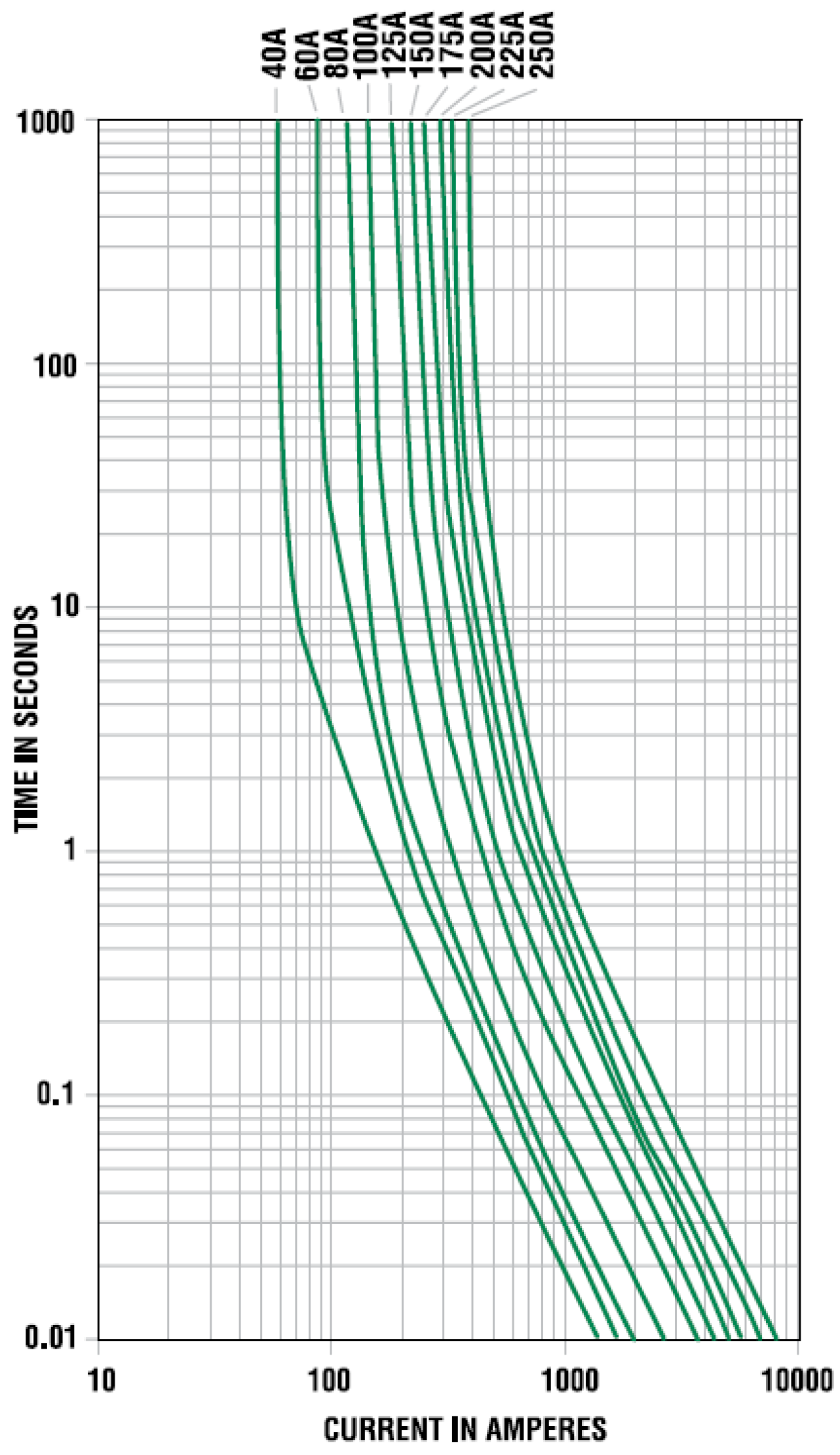
The desired maximum current for the overall system is 100 A. Therefore, the protection circuitry which comprises of a fuse and a contactor is chosen accordingly. The selected fuse is a 40 A bolt-down fuse from Littlefuse (Chicago, IL, USA) which is rated for 32 VDC and interrupting current of 2000 A at 32 VDC.
Figure 2 shows the opening time
versus current value for a family of this fuse. As can be seen from this figure, it takes about 5 s at a current value of 100 A for the fuse to open.
Figure 2.
Characteristic curve for a 32 V rated Mega fuses from Littlefuse.
Figure 2.
Characteristic curve for a 32 V rated Mega fuses from Littlefuse.
The protection unit has a 600 VDC, 100 A hermetically sealed DC contactor. Its coil is rated for 9–32 VDC and a maximum pickup current of 1–5 A at 20 °C. A MOSFET amplifier is designed in order to drive the contactor with the digital output from the controller.
Finally, a programmable power supply and electronic DC load pair from BK Precision (Yorba Linda, CA, USA) is used in order to charge and discharge the battery. The programmable power supply (model number XLN6024) is capable of delivering 1.44 kW power in constant current and voltage modes. The model 8514 programmable DC load can absorb a maximum power of 1.2 kW in constant current, voltage, resistor, and power modes. Communication with the DC load and power supply is established through serial ports using NI LabVIEW.
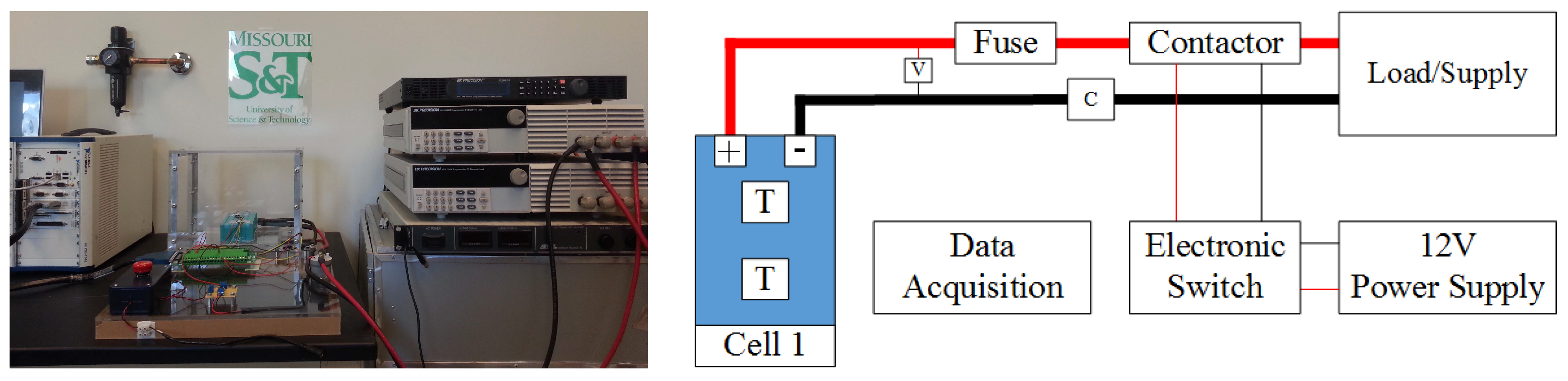
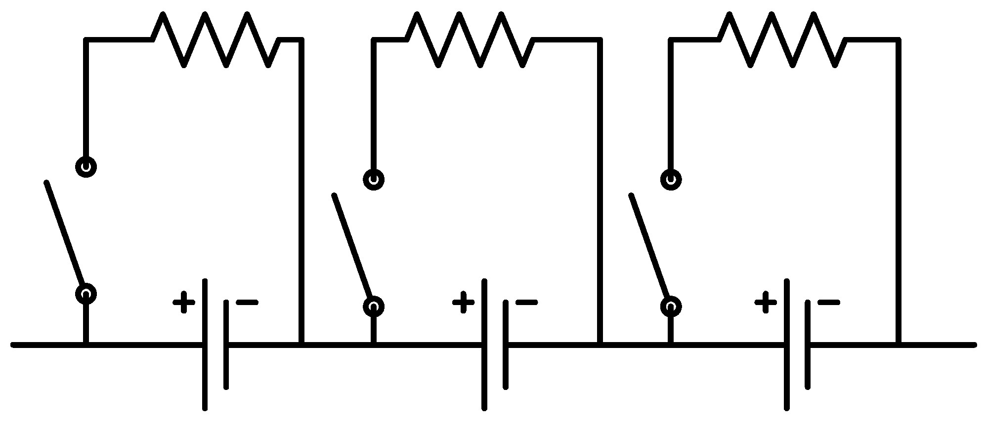
The experimental Li-ion research testbed is designed to operate in three configurations in order to cover a wide variety of research areas in Li-ion battery systems. The first configuration is a single cell research platform. The focus of this platform, which is shown in
Figure 3, is to perform different tests on individual battery cells. These tests target electrical and thermal characterization and modeling of the individual cells and the analysis of discrepancies between seemingly identical cells. Efficient thermal and electrical protection unit architectures can also be studied. Finally, high power performance and modeling analysis for battery cells can be addressed using this platform.
Figure 3.
Single cell research platform with its schematic diagram.
Figure 3.
Single cell research platform with its schematic diagram.
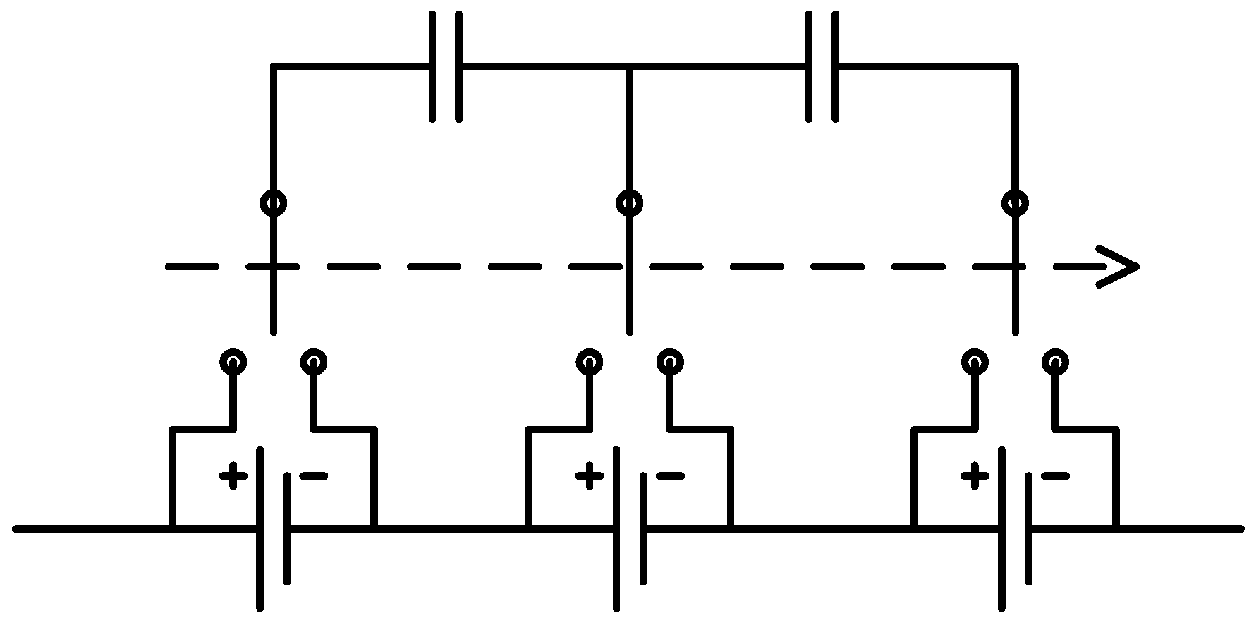
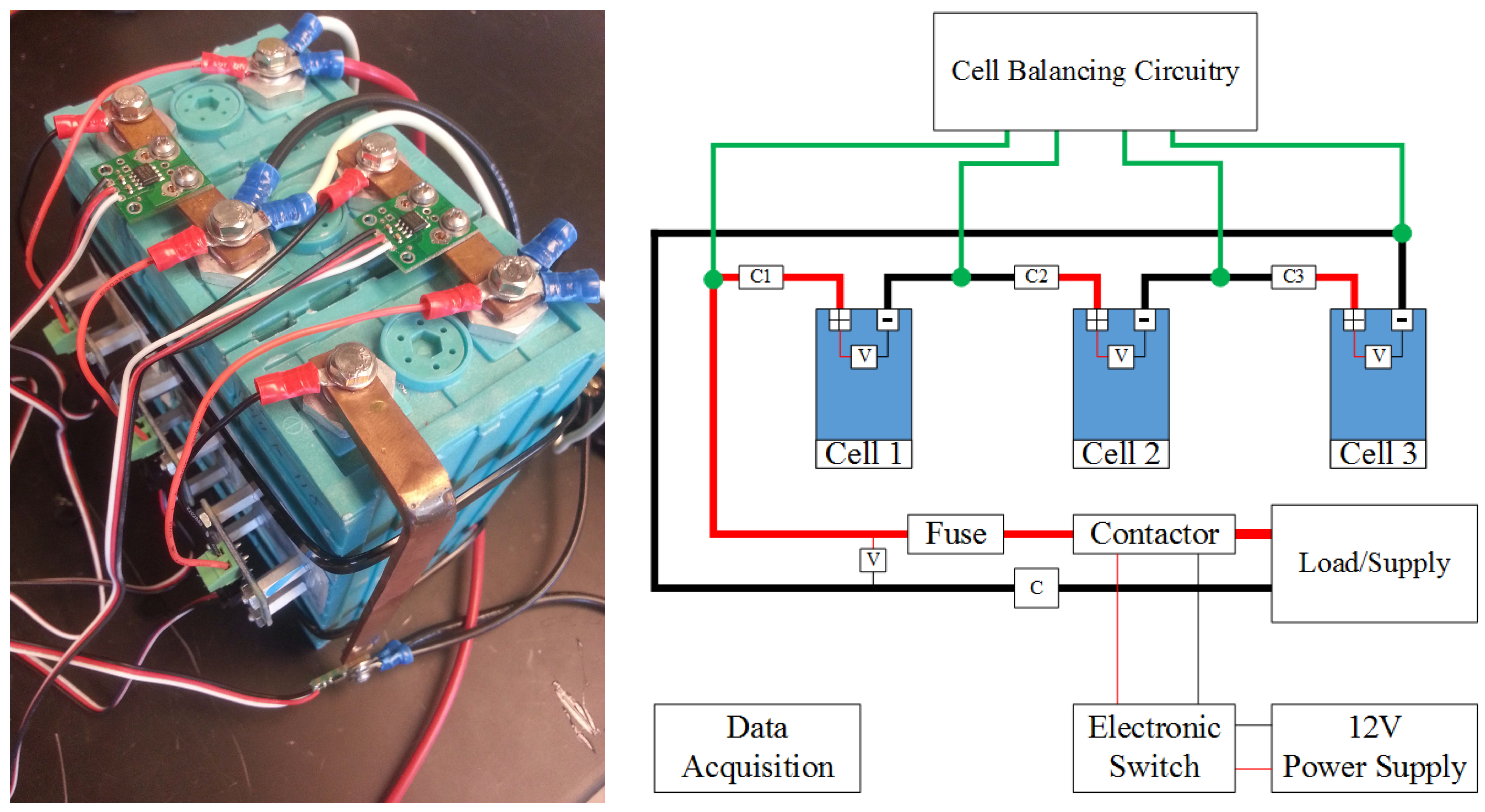
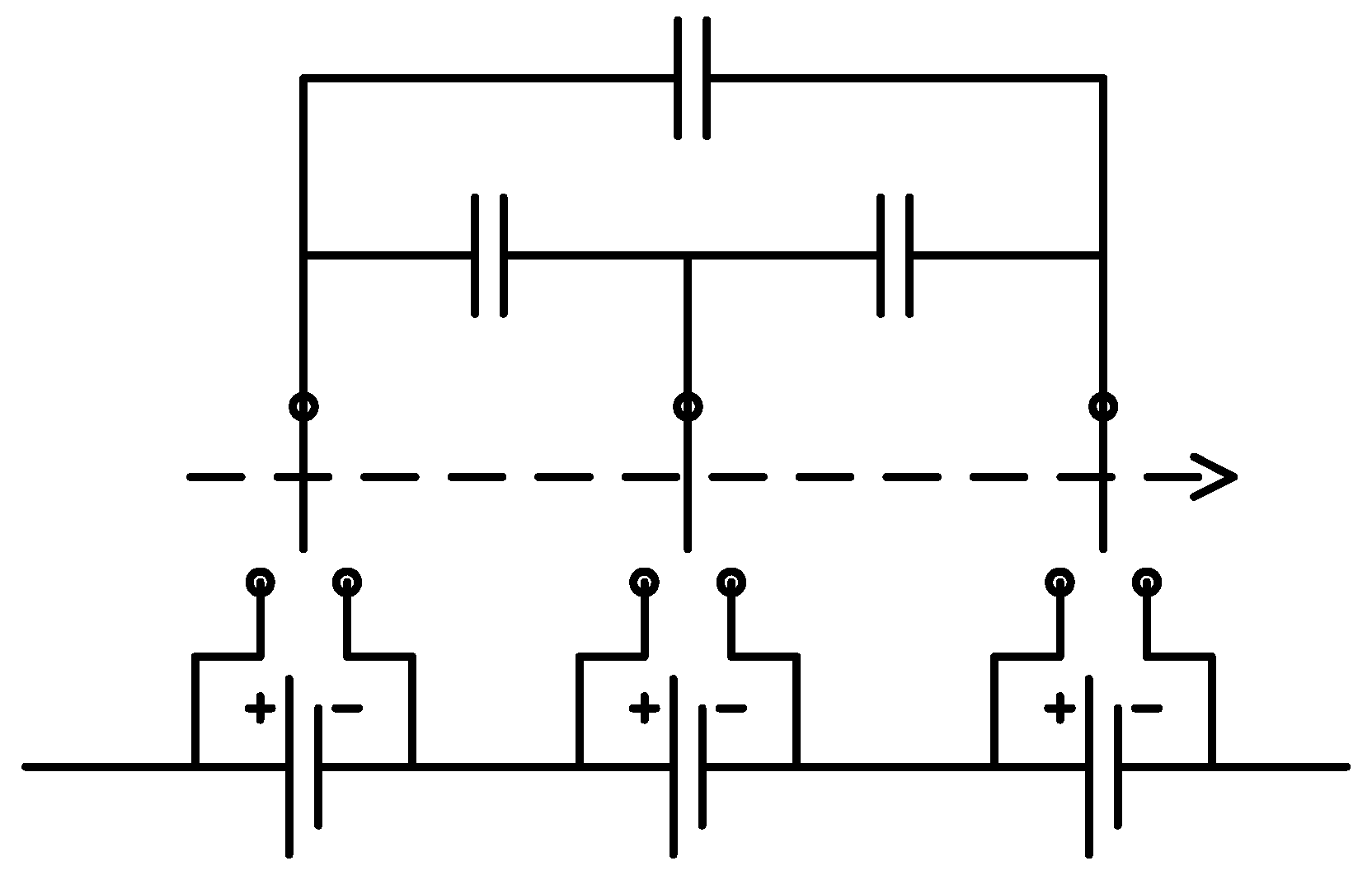
The second platform addresses cell balancing during battery operation. Cell balancing is undoubtedly the most significant during charging as any imbalance among cells can result in overvoltage and, therefore, safety hazards. In order to study this important functionality, the second platform consists of three battery cells in series with each other. In addition to individual voltage sensors for cells, they are also equipped with individual current sensors to facilitate examining their current and, therefore, capacity evolution during different cell balancing strategies. This configuration is depicted in
Figure 4.
Figure 4.
Cell balancing research platform with its schematic diagram.
Figure 4.
Cell balancing research platform with its schematic diagram.
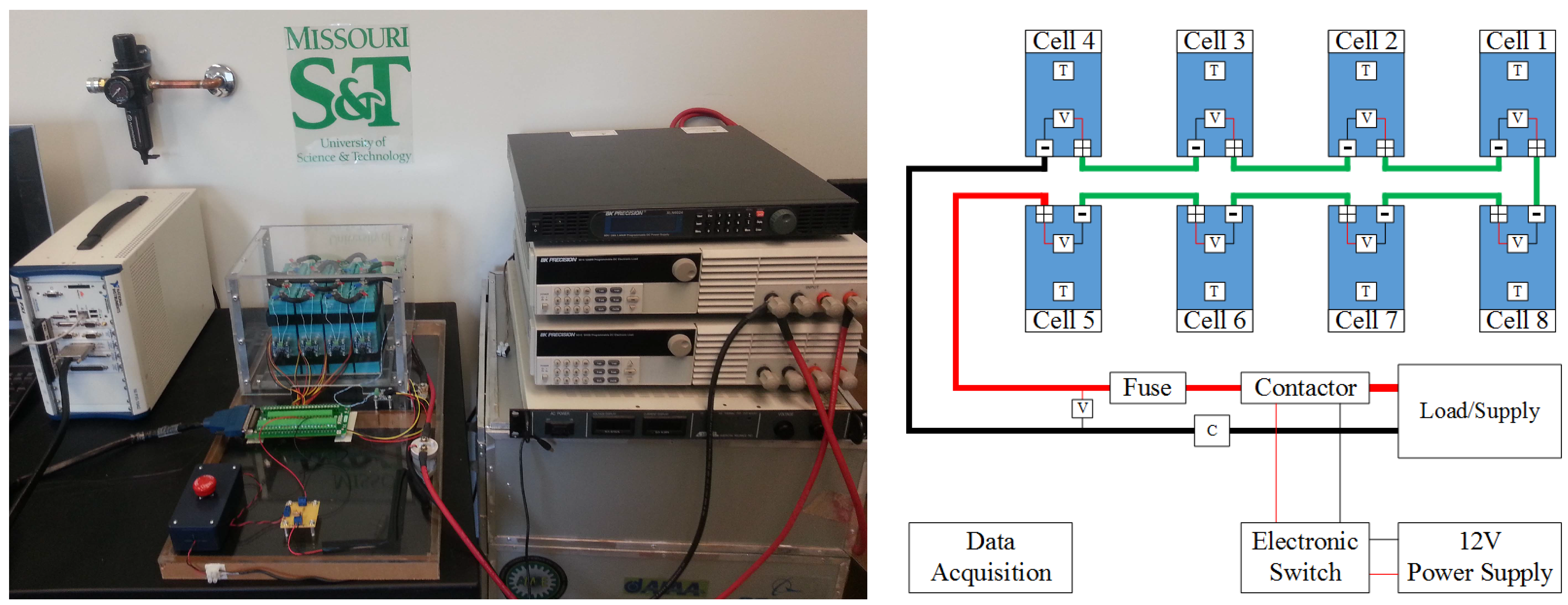
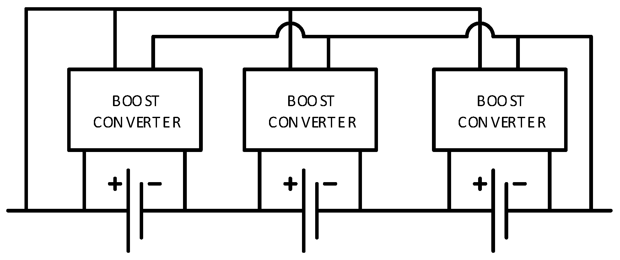
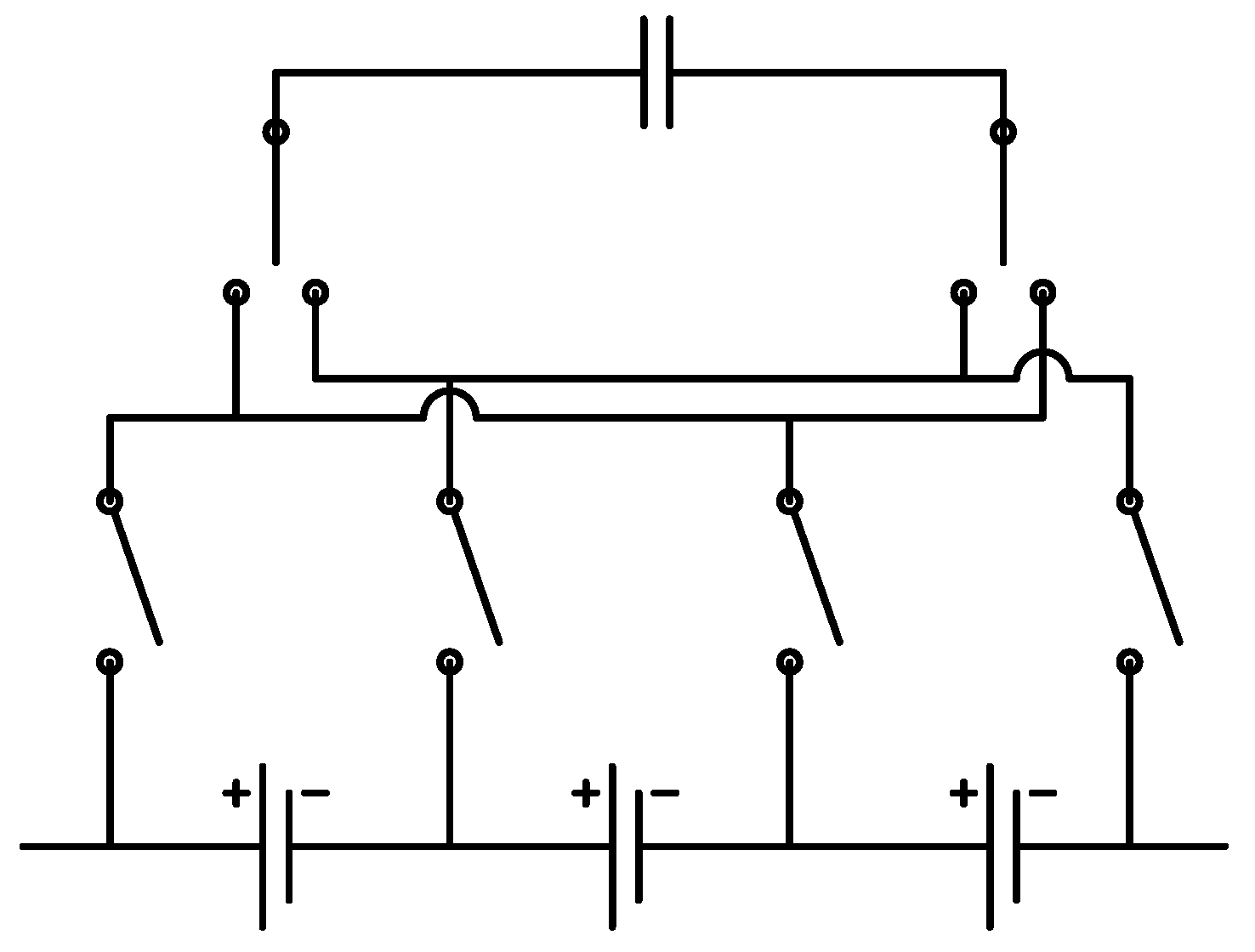
The last platform is a complete eight cell battery pack with voltage and temperature sensors for each cell and a pack current and voltage sensor. This platform is devised to address issues encountered in battery packs such as battery pack modeling and state estimation, temperature distribution and thermal management, a cell balancing strategy addressing both charging and discharging, and efficient electrical protection of the battery packs.
Figure 5 shows the battery pack setup with its corresponding schematic diagram.
Figure 5.
Battery pack research platform with its schematic diagram.
Figure 5.
Battery pack research platform with its schematic diagram.
In the following sections, different BMS functionalities are discussed in more detail. Considerations that should be taken into account in designing each subsystem and future improvements that can be integrated in BMS technologies are introduced. Some initial characterization test results are also reported.
5. Protection
The protection subsystem in the BMS is intended to guarantee the battery operates in its safe region. Battery voltage, current, and temperature are factors determining the safe operating region. Some of the harmful effects of running the battery outside of this region were briefly reviewed in the Introduction based on information from [
15]. Two important aspects should be taken into account when designing a battery protection subsystem: when to react to a detected range violation and how to handle such a condition. In this section, these aspects will be studied for voltage, current, and temperature protection. Furthermore, the protection subsystem architecture devised for the experimental battery testbed is discussed.
The operating voltage of Li-ion batteries is dictated by their chemistry. More specifically, the material used in the cathode structure determines the battery voltage limits. For the battery chemistry used in the experimental testbed, which is described in
Table 1, the operating voltage should be between 2.5 V and 3.8 V. Therefore, the BMS should ensure the individual cell voltages remain in this range at all times. It should be noted that it is more efficient to impose voltage limits on the battery open-circuit voltage rather than the battery terminal voltage. However, battery open-circuit voltage is not measurable during battery operation and an estimation algorithm should be implemented to obtain battery open-circuit voltage from its measurable signals,
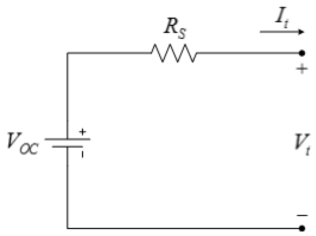
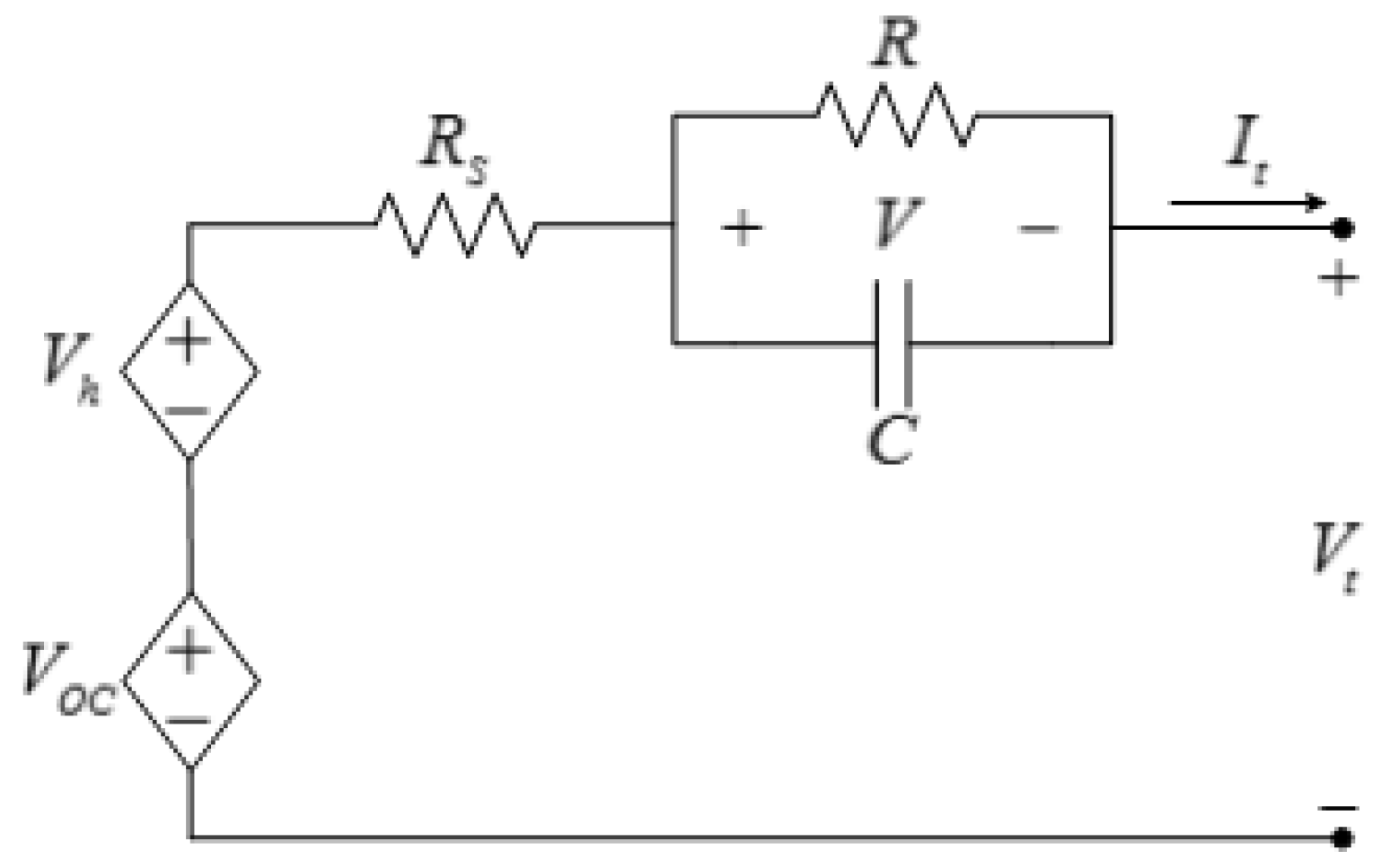
i.e., voltage, current, and temperature. The easiest method to estimate battery open-circuit voltage is to use the equivalent-circuit model shown in
Figure 22.
Figure 22.
Equivalent-circuit battery model.
Figure 22.
Equivalent-circuit battery model.
Applying Kirchhoff’s voltage law to the circuit in
Figure 22, the battery open-circuit voltage is:
where
RS is calculated from open-circuit voltage tests, as described in
Section 3.1.3. In order to estimate battery open-circuit voltage using Equation (8), the average value of
RS, which is 0.0189 Ω, is used.
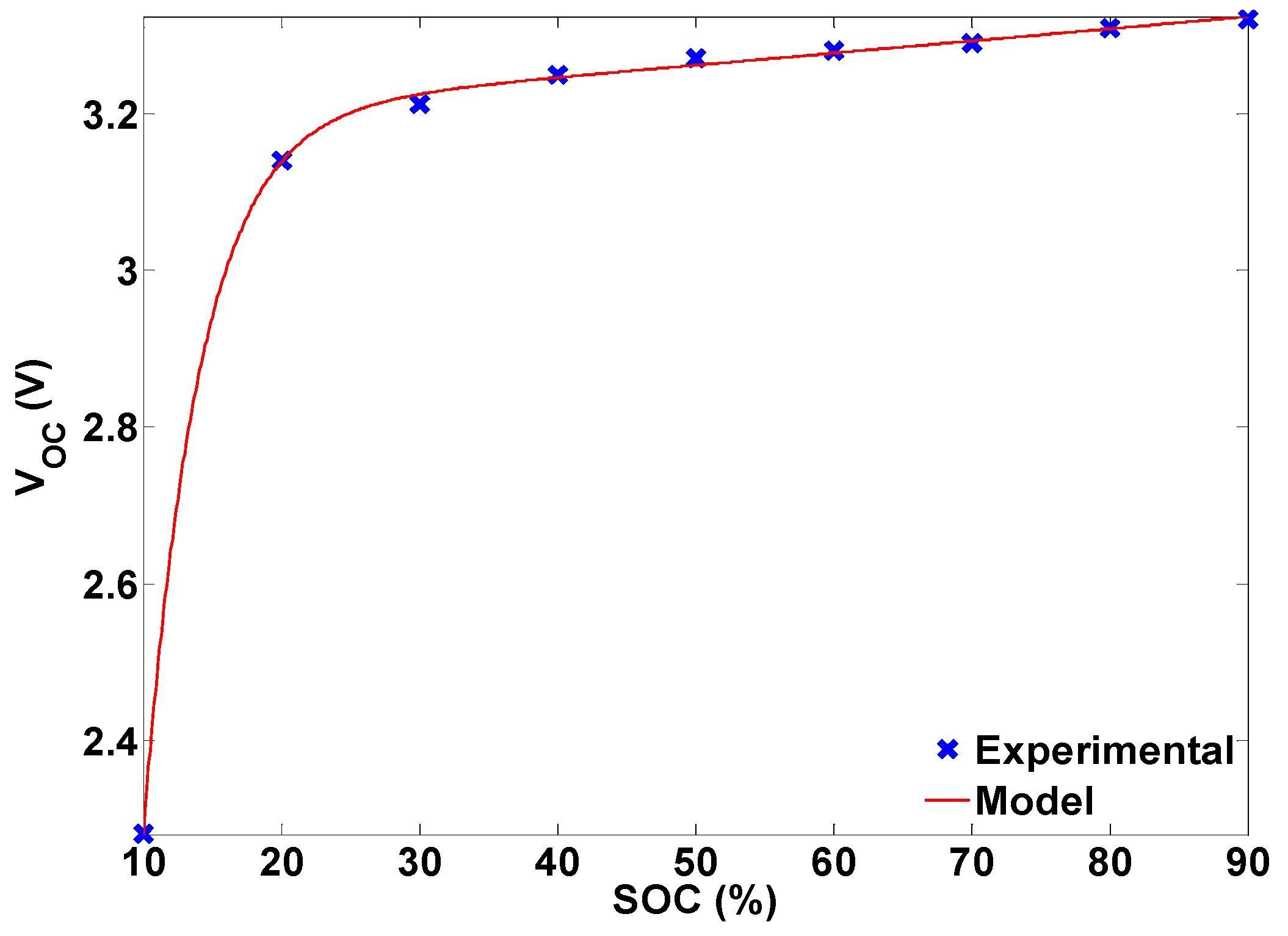
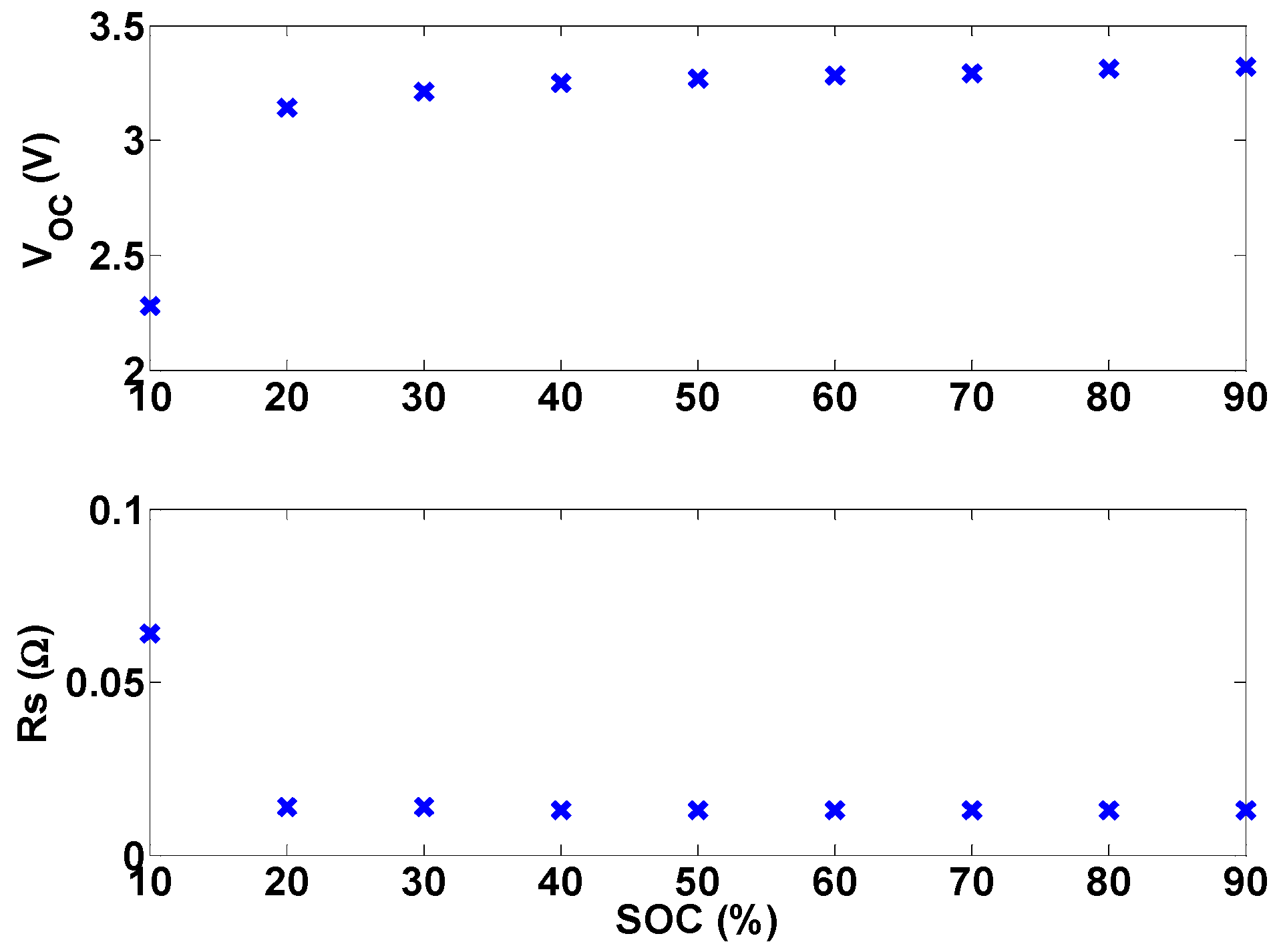
Another method to obtain battery open-circuit voltage, assuming an accurate SOC estimate is available, is to use the open-circuit voltage-SOC relationship. This relationship can be obtained from fitting the following model to the experimental data in
Section 3.1.3:
Figure 23 shows the fitted model Equation (9) and the experimental results. It is proposed in [
17] that the time average of the battery terminal voltage should be used as the protection criteria instead of the terminal voltage.
Figure 23.
Experimental and modeled battery open-circuit voltage.
Figure 23.
Experimental and modeled battery open-circuit voltage.
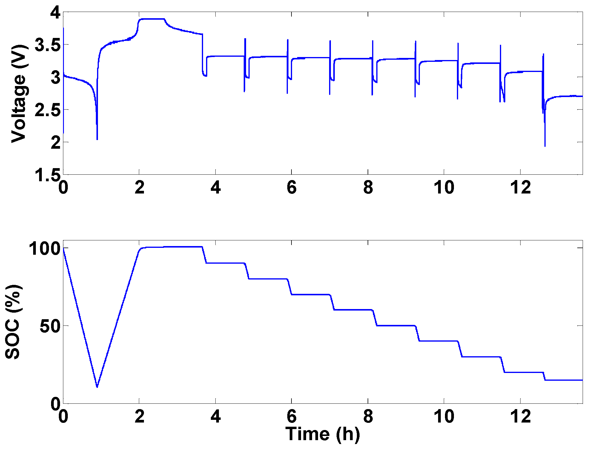
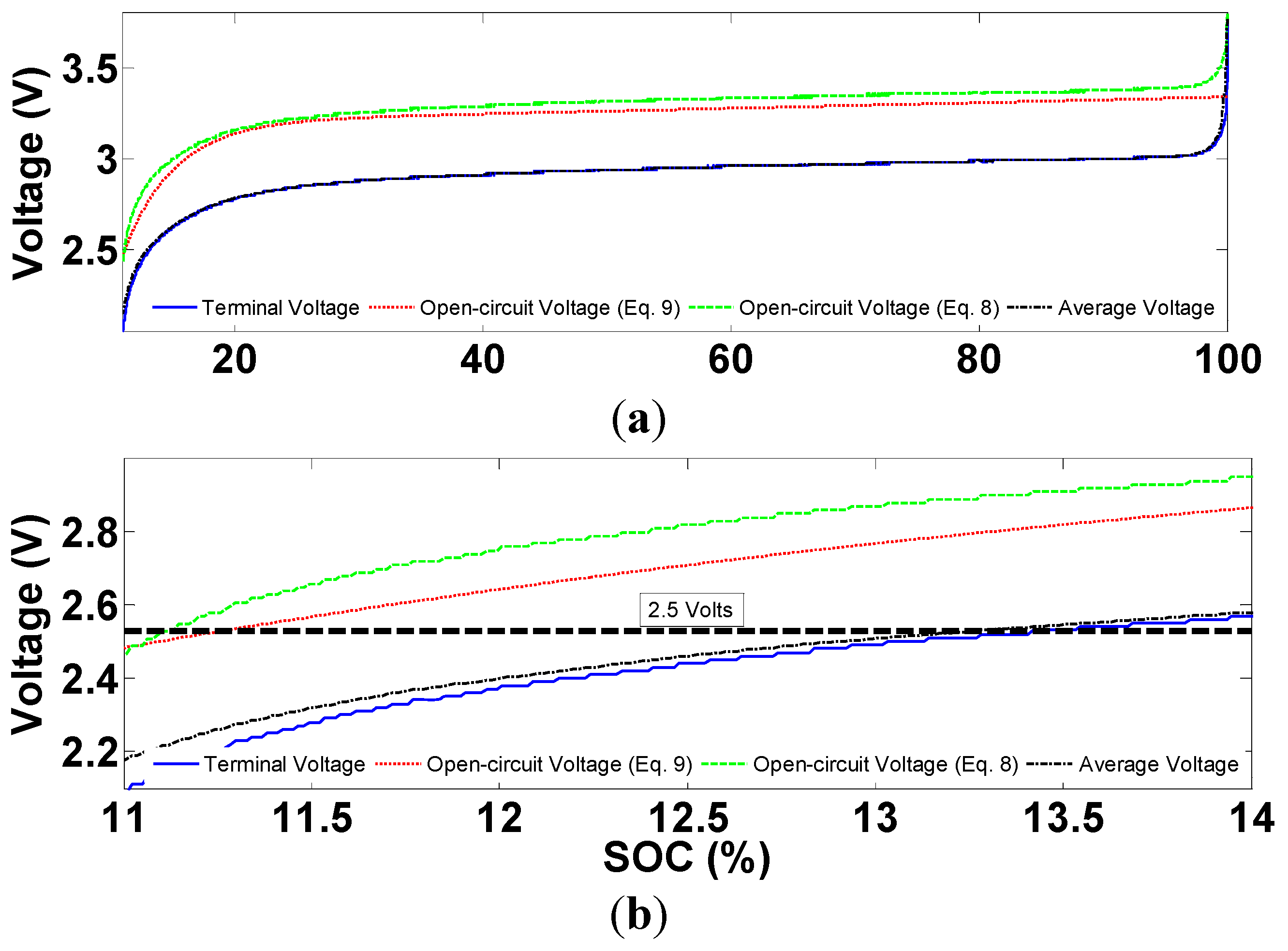
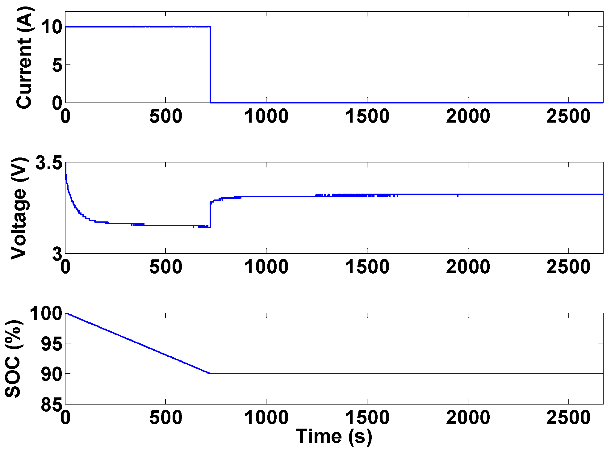
Figure 24 shows the evolution of terminal voltage, open-circuit voltage obtained using the above two methods, and the time average of terminal voltage during a complete battery discharge.
Figure 24.
Comparison of different voltage levels during a discharge profile: (a) the whole profile; and (b) end of discharge.
Figure 24.
Comparison of different voltage levels during a discharge profile: (a) the whole profile; and (b) end of discharge.
As can be seen from
Figure 24, more energy can be extracted from the battery, before the manufacturer’s low cut-off voltage is approached, if the open-circuit voltage obtained from Equation (8) is used in the protection system. It should however, be noted that Equation (8) is just an approximation of the open-circuit battery voltage. Substantial research is still needed in designing less conservative and more efficient Li-ion battery protection systems. The results presented in
Figure 24 are obtained from a constant-current discharge profile. Investigating the performance of protection system during dynamic current profiles is also an important research topic in BMS development.
Finally, there are some recent studies which focus on observing internal battery parameters such as lithium concentration in the negative electrode instead of battery voltage as the protection criteria [
11,
38]. The authors claim that by considering such protection criteria for batteries more energy can be extracted while maintaining safe battery operation. More research still needs to be conducted to facilitate on-line implementation of such algorithms.
Once a voltage limit is being approached, the battery’s protection system will react to it in one of the following three ways: interrupt the current, ask an external system component to interrupt the current, or communicate with the load and command it to limit the current it is drawing from the battery. The protection units, which will interrupt the current autonomously, are called protectors [
17] but are not studied here. The other two reactions of the protection unit, however, are implemented in the experimental testbed. The choice of which reaction to choose depends on the application. Specifically, current limiting is usually preferred in applications where continuous current supply is vital.
The safe operating range for the battery current is usually determined by its physical structure and manufacturing specifications. As can be seen in
Table 1, four current limits are specified for batteries in the datasheet: continuous charging, peak charging, continuous discharge, and peak discharge. As soon as the continuous battery charge/discharge current is exceeded, the protection unit needs to monitor the excess current duration and calculate the SOC variation in this period. It then only has to take action if the SOC reaches 0% or 100%. In this way, peak charge/discharge currents will also be tolerated for specific time periods. The protection unit reaction can be any of the scenarios described for voltage range violation. It should also be noted that in order to achieve the protection for both charge and discharge, the BMS needs to be able to differentiate between charge and discharge by assigning a current sign convention, e.g., positive for discharge and negative for charge.
The operating temperature range for Li-ion batteries which is usually between −20 °C and 55 °C is very likely to be violated in applications such as transportation. In order to circumvent the undesirable effects of temperature range violation, an efficient thermal management subsystem is required. The thermal management subsystem monitors cells and/or pack temperatures and maintains their temperatures within desired ranges. Depending on the BMS complexity and ambient battery temperature, the thermal management system might incorporate passive cooling, active air or liquid cooling, or refrigeration. Another important issue regarding the temperature of Li-ion batteries is a phenomenon called “thermal runaway.” Thermal runaway can occur due to ambient conditions, structural defects, or battery abuse. In any case, thermal runaway is usually not detectable by temperature sensor measurements as the internal temperature of li-ion battery cells is significantly higher than their casing temperature. This issue may be prevented by implementing an estimation algorithm capable of monitoring internal cell temperature. Thermal management system design and internal battery temperature estimation are among two future studies that will be conducted on the experimental testbed.
6. Indication of Battery States
Li-ion battery states include the battery’s operational conditions that affect the performance of the battery and also the systems connected to it. These states include SOC and SOH. SOC shows the amount of charge remaining in the battery compared to a full battery. In other words, it is an indication of the operation scope of the battery-powered device. From an electrochemical point of view, SOC is the ratio of the lithium ion concentration to the maximum lithium ion concentration in the negative electrode (limiting electrode). It is mathematically defined by:
where
Qnom is the nominal capacity (A∙h);
It(
t) is the battery terminal current;
t0 is the initial time (s); and
t is the elapsed time (s). Equation (10) cannot be used in practice to obtain SOC due to issues arising from measurement noise in
It and also the unavailability of
SOC(
t0) in different applications. Therefore, since SOC is not measurable, an estimation algorithm is usually required to estimate the SOC using the battery’s measurements,
i.e., current, voltage, and temperature. Although the majority of SOC estimation algorithms rely on a battery model to acquire SOC, some non-model based methods have also been proposed. Among these types of methods, a combination of battery current integration, using Equation (10), and the voltage translation method is the most common one. The voltage translation method is based on the battery voltage
versus SOC relationship and is typically used to calibrate the current integration method. Model-based methods, on the other hand, employ either an electrochemical model or an equivalent-circuit model. As mentioned earlier, [
10,
11,
28,
29,
30] are some of the works recently conducted on SOC estimation based on full-order or reduced-order electrochemical models. However, due to the aforementioned implementation simplicity of equivalent-circuit models, there is a large body of literature using equivalent-circuit models to estimate battery SOC. In these works, different battery models are used along with an estimation algorithm such as Extended Kalman Filter [
26,
39], sliding-mode observers [
24,
40], adaptive observers [
41], and linear parameter varying (LPV) observers [
42].
Battery SOH is an indication of battery status compared to a fresh battery. In other words, it captures battery cycle life and aging effects. There is not a universal definition for SOH and different battery parameters are considered as indications of SOH. Among these parameters, battery capacity and internal resistance are the most popular ones. Due to the arbitrary definition of SOH, different authors [
40,
41,
42,
43] have used different methods and criteria to obtain SOH. The majority of SOH estimation algorithms employ a parameter identification method such as Kalman filtering [
44] or adaptive estimators [
45] in order to obtain some battery parameters. In these studies, the changes in parameters such as internal resistance or battery capacity are considered to be the SOH.
At the initial stages of the experimental testbed development, battery state of charge is obtained using the combination of current integration and voltage translational methods, as explained earlier. Although this combination is one of the most-commonly used SOC indication algorithms, the sliding-mode observer introduced in [
24] will be used in the future due to this method’s intrinsic robustness against model uncertainties. As mentioned earlier, the main focus of this testbed in the future will be to design SOC and SOH algorithms for battery packs. This research area is of utmost importance in real world applications; however, it has not received much attention in the literature.

