1. Introduction
Recently, there has been growing interest in energy storage systems (ESSs) because of their use as a renewable energy supply and power increases at peak hours [
1]. The ESS allows the highly efficient usage and stable management of power. When the power demand is low, the ESS stores electricity. On the other hand, the ESS provides this stored electricity when the power demand is high [
2,
3,
4].
The grid-side power pulsates at twice the grid frequency because the voltage and the current on the grid are AC components. This causes a 120 Hz ripple on the battery-side voltage and current [
5,
6]. In single-phase systems, a second-order harmonic component occurs systematically. In ESS, the lifetime of the battery is an important issue for the power efficiency. The reactive power is generated by an internal impedance of the battery and current ripple. This reactive power causes an increase in the temperature of the battery, which reduces the battery lifetime. The lifetime of the battery is affected by temperature, current ripple, overcharge and so on [
7]. In order to reduce the harmonics component in the grid connected system, passive power filters (PPFs), active power filters (APFs), digital algorithms and proportional-resonant (PR) controller are proposed. PPFs have the advantage that the filter can be easily designed by using passive devices like inductors and capacitors, but PPFs have problems such as detuning, resonance, instability and limitation of the possible frequency adjustment [
8,
9]. APFs can reduce the harmonic component using the compensation current which has the opposite phase of the harmonic component. However, APFs have a high operation cost, due to their extra hardware and complex control [
10]. Unlike PPFs and APFs, digital algorithms which use a calculated ripple current compensation method do not cause an increase of the cost and volume. The calculated ripple current compensation method can reduce the harmonic current without complex calculations. However, this method cannot completely reduce harmonic current when the parameters are changing under various conditions [
11]. Because of these problems, the ripple rejection algorithm with a proportional-resonant (PR) controller is proposed in [
12,
13]. A proportional-resonant (PR) controller has a high gain and a narrow bandwidth at the resonant frequency. If the resonant frequency of the PR controller is designed to the second-order harmonic frequency, the harmonic compensator using the PR controller extracts and controls the second-order harmonic component. However, the harmonic compensator using the PR controller sufficiently does not reduce the second-order harmonic component during frequency variation [
14,
15,
16].
This paper proposes a second-order harmonic reduction algorithm using the PI controller. The conventional method for reducing the second-order harmonic does not sufficiently reduce the second-order harmonic component during the frequency variation. The proposed algorithm has an advantage of reducing the second-order harmonic during frequency variation situations. The current ripple reduction improves the lifetime of the battery. The proposed algorithm is verified by PSIM simulation and experiments for a 3 kW home ESS.
2. Energy Storage System Topology
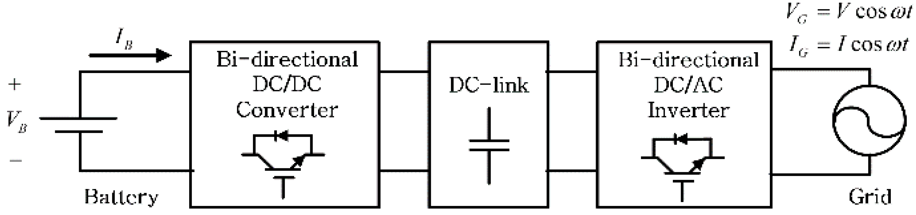
Figure 1 shows a general grid-connected ESS in single-phase system. The ESS consists of a battery, bi-directional DC/DC converter, bi-directional DC/AC inverter and filter. An interleaved topology composed of two converters connected in parallel is used to reduce the switching ripple in the battery-side current. Because the ESS needs the bi-directional power transfer, a bi-directional DC/DC converter and the bi-directional DC/AC inverter are required. The DC/AC inverter controls the DC-link voltage and power factor. On the other hand, the DC/DC converter regulates the output current.
Figure 1.
Block diagram of the ESS.
Figure 1.
Block diagram of the ESS.
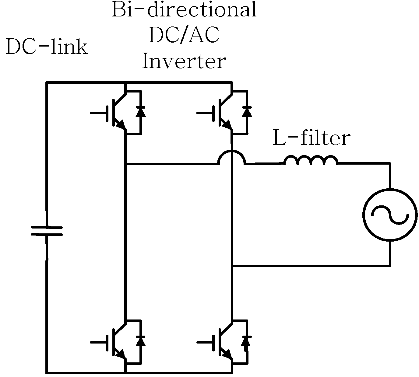
2.1. Grid Connected DC/AC Inverter
The full-bridge topology is adopted to set the DC/AC inverter for the proposed ESS as shown in
Figure 2. The single-phase full-bridge inverter converts from the AC to DC constant voltage.
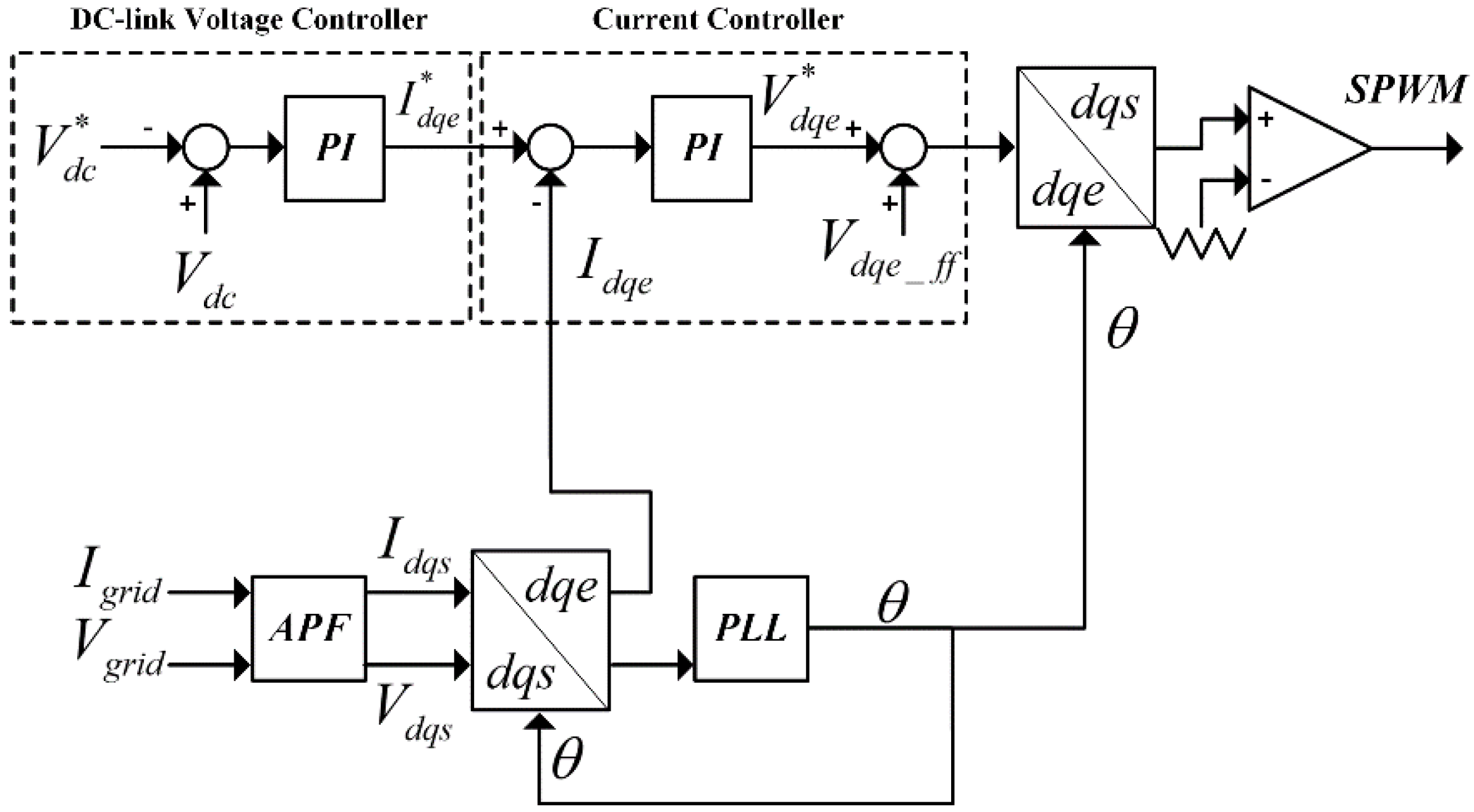
Figure 3 shows a block diagram of the control scheme for the grid connected inverter in the single-phase system. This inverter regulates the DC-link voltage using a typical PI controller. To use the PI controller, a synchronous reference frame is required. In the single system, there is a need to create an imaginary axis because only one axis exists. An all pass filter (APF) has characteristic which passes all frequencies equally and shifts the phase by 90 degrees. The APF is used to make an imaginary axis because of the characteristics mentioned above. The phase angle which is estimated by the phase locked loop (PLL) is used in the synchronous reference frame. The grid voltage and current are converted to active and reactive components by using the synchronous reference frame and APF. The output of the DC-link controller is the active component which is the reference grid current. The inverter controls the power factor at 1 because the current controller controls the reactive component at zero and the active component to the reference grid current.
Figure 2.
Construction of the grid connected inverter.
Figure 2.
Construction of the grid connected inverter.
The DC-link controller is the main-controller and the current controller is the sub-controller as shown in
Figure 3. In the charging mode, when the reference DC-link voltage is higher than the DC-link voltage, the DC-link voltage controller increases the reference grid current. The DC-link voltage controller decreases the reference grid current in the reverse case.
Figure 3.
Block diagram of the control scheme for the grid connected inverter.
Figure 3.
Block diagram of the control scheme for the grid connected inverter.
2.2. DC/DC Converter
Figure 4 shows the interleaved bi-directional converter used in the proposed ESS. The bi-directional converter is composed of a power semi-conductor switch, capacitor, and inductor. The bi-directional converter can operate in buck and boost mode according to the power flow of the ESS. The converter works with the buck mode in the charging mode and with the boost mode in the discharging mode.
Figure 4.
Construction of the bi-directional DC/DC converter.
Figure 4.
Construction of the bi-directional DC/DC converter.
To reduce the current ripple of the converter, an interleaved topology is used. The interleaved converter has many advantages over a single phase converter. In the interleaved topology, the total current ripple is reduced due to the current of each phase being overlapped and there is an effect where the switching frequency is two times higher than that of the single phase topology. Also, the stress of the switch is smaller because the total current is divided into two phases.
Figure 4 shows the bi-directional DC/DC converter. When the system operates in the charging mode, the converter operates in buck mode. The buck mode converter produces a lower average output voltage than the input voltage. The output average voltage is linearly varied by the duty ratio
Dbuck which is the ratio of the on time of the switch P and the period of switching [
17]. The switch N works as a freewheeling diode and is complementarily switching P. Under this condition, the DC-link provides energy to the battery as well as to the inductor because the current flows from the DC-link to the battery. In a steady state, the voltage transfer ratio
Gv is:
Because Dbuck is between 0 and 1, VB is always lower than that of the DC-link.
When the system operates the discharging mode, the converter operates in boost mode. Unlike the buck mode, the output voltage is always greater than the input voltage in the boost mode. By varying the duty ratio Dboost which is the ratio of the on time of the switch N, the output average voltage is controlled. P is complementarily switching N. In boost mode, the input voltage is the voltage of battery and the output voltage is the voltage of the DC-link.
The battery provides energy to the DC-link because the current flows from the battery to the DC-link. In a steady state, the voltage transfer ratio
Gv is:
Because Dboost is between 0 and 1, VDC is always higher than VB.
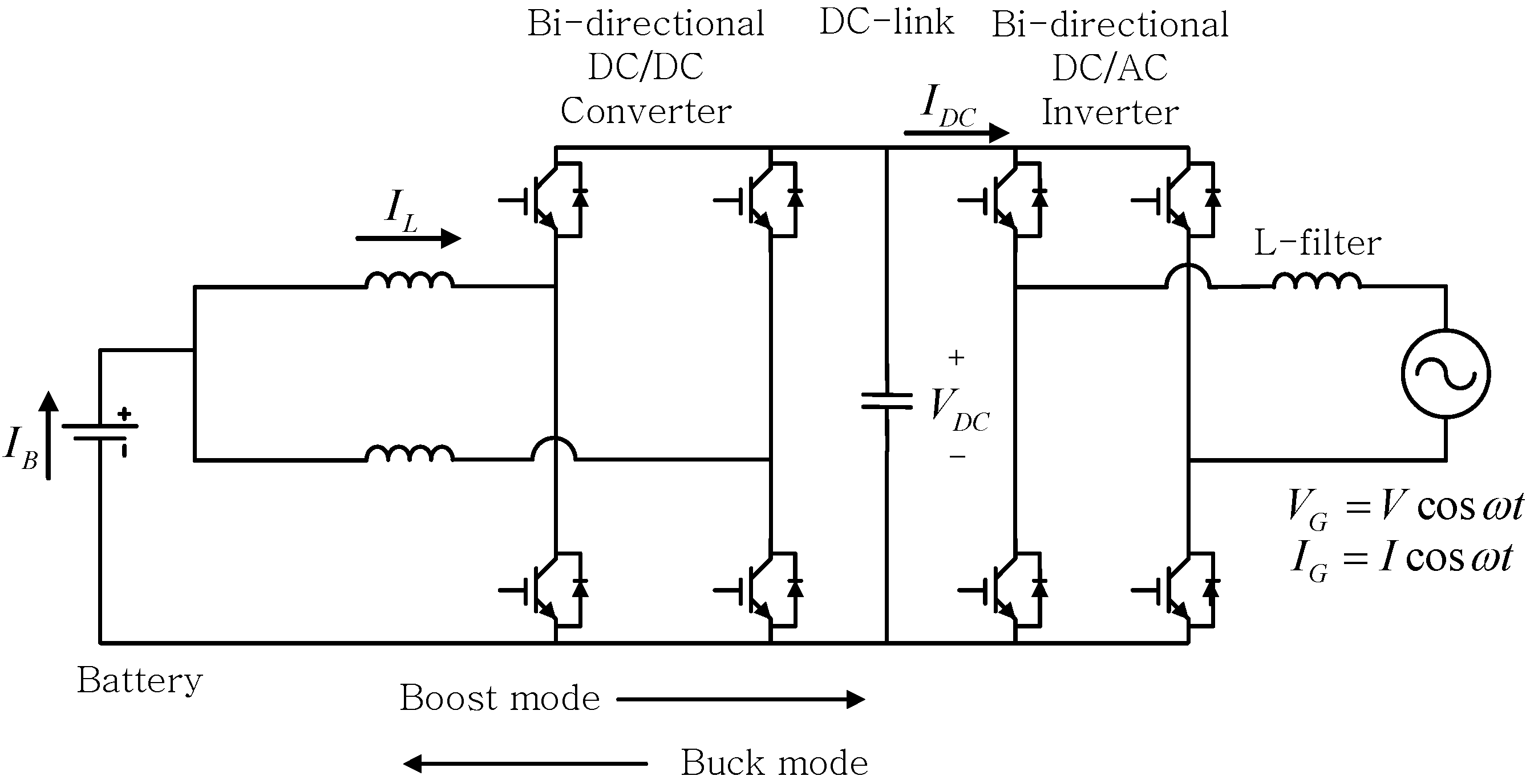
2.3. Mechanism of 120 Hz Ripple Occurrence
Figure 5 shows the ESS grid connected system in the single-phase system. The power equations for the grid-side and DC-link-side are:
where ω (= 2πf) is the frequency of the grid.
Figure 5.
Construction of the grid connected ESS system.
Figure 5.
Construction of the grid connected ESS system.
The DC-link-side power is the same as the grid-side power. From Equations (3) and (4), the DC-link-side current can be calculated as:
where
Idc is DC component and
Idc(ac) is AC component.
The DC-link voltage ripple
Vdc(ac) can be derived by the ripple of the DC-link current
Idc(ac). The DC-link voltage ripple
Vdc(ac) is:
From Equation (6), the DC-link voltage has an AC component Vdc(ac). Thus VDC and IDC consist of a DC and an AC component. The AC component of IDC and VDC has a second-order harmonic at twice the grid frequency.
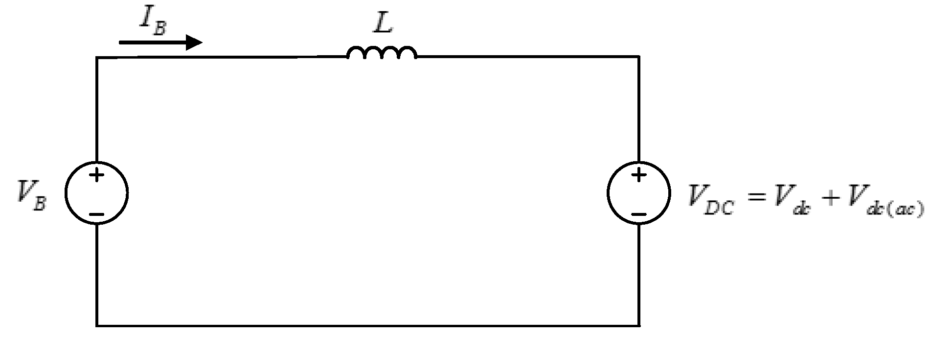
Figure 6 shows the equivalent circuit of converter. The battery voltage can be seen as only DC voltage. If there is the power flow between the battery and the DC-link, the battery current
IB has an AC component because of
Vdc(ac). In the same manner,
IB has the second-order harmonic at twice the grid frequency.
Figure 6.
Equivalent circuit of DC/DC converter.
Figure 6.
Equivalent circuit of DC/DC converter.
2.4. Harmonic Reduction Algorithms Using PR Controller
In a grid connected system, the harmonics adversely affect the efficiency of the power transfer and the power quality. To solve these problems, many harmonic reduction methods which are PPFs, APFs, digital algorithm and others are proposed. However, these harmonic reduction methods have some disadvantages in the stability of a system, limitation of parameters, cost and so on. The PR controller is used in the harmonic compensator to solve the problems mentioned above. In an ideal situation, the PR controller has the characteristics which are the infinity gain, a zero phase shift and narrow bandwidth. The PR controller eliminates the steady-state error when regulating sinusoidal signals.
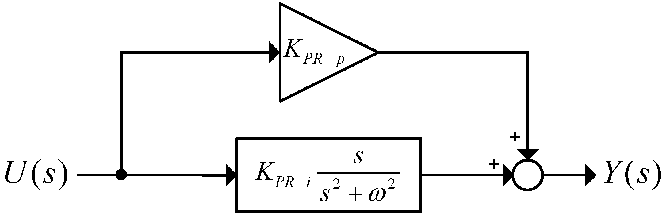
Figure 7 shows the block diagram of the PR controller and the transfer function can be expressed by:
where
KPR_p and
KPR_i are gain constants and
ω is the resonant frequency.
Figure 7.
Block diagram of the PR controller.
Figure 7.
Block diagram of the PR controller.
In the ideal condition, the PR controller has an infinite gain at the resonant frequency. However, the nonideal PR controller using a high gain low pass filter (LPF) is used because the infinite gain makes the system unstable. The transfer function of the nonideal PR controller is expressed by:
where
ωc is the cut-off frequency.
From the equation above, the nonideal PR controller has a sufficiently high finite gain and the bandwidth is adjusted by the cut-off frequency. If the resonant frequency is designed to be the harmonic frequency, the nonideal PR controller can extract and control the harmonic component because of these characteristics mentioned above. The transfer function of the harmonic compensator is expressed by:
where
h is the harmonic order. To use the second-order harmonic compensator, the resonant frequency is designed to be the frequency of second-order harmonic.
Figure 8 shows the block diagram of the current controller with the second-order harmonic compensator. If the grid frequency is changed, the compensator does not completely extract the second-order harmonic because the PR controller has an arrow bandwidth in the middle of the resonant frequency. Therefore, the compensator using the PR controller does not reduce sufficiently the second-order harmonic under variable conditions.
Figure 8.
Block diagram of the current controller with the second-order harmonic compensator using the PR controller.
Figure 8.
Block diagram of the current controller with the second-order harmonic compensator using the PR controller.
2.5. Proposed Second-Order Harmonic Reduction Algorithm
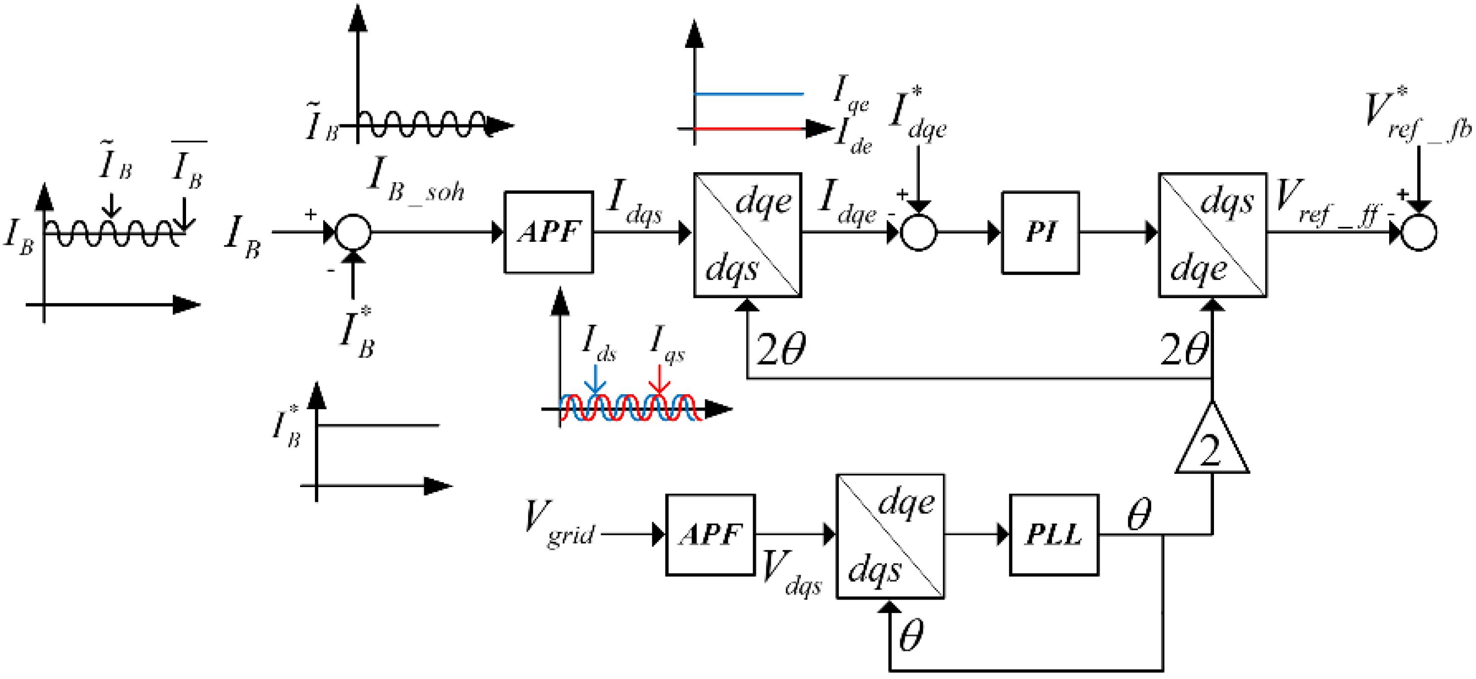
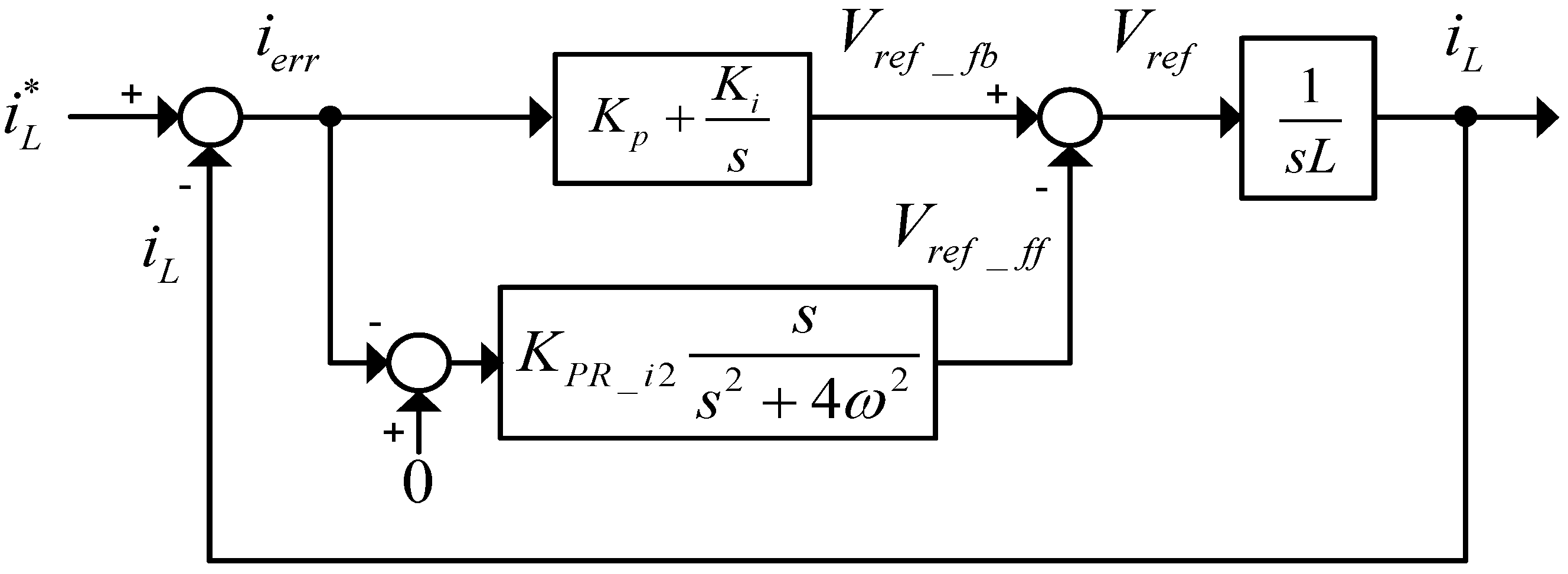
Figure 9 shows a block diagram of the proposed harmonic compensator. To reduce and control the second-order harmonic, the harmonic compensator is required to extract the harmonic components. The current of the battery is composed of AC currents due to the pulsation of the DC-link voltage and DC currents. The current of the battery
IB can be expressed by:
where “~” means the AC component and “–” means the DC component.
Figure 9.
Block diagram of the PI controller with the harmonic compensator.
Figure 9.
Block diagram of the PI controller with the harmonic compensator.
If the battery current tracks the reference current,
is the same as the reference value and
becomes the ripple component of the current. By subtracting
from
IB, the second-order harmonic
can be obtained as:
The ripple frequency becomes twice the grid frequency. The synchronous reference frame is required to use the PI controller in the proposed harmonic compensator. There is a need for the synchronous reference frame to change the control variable of AC to DC because the PI controller is not suitable to control the signal which has the periodic change such as the AC signal.
Ids can be seen as
converting
Ids to the synchronous reference frame. There is a need to create an imaginary axis in single-phase systems. An all pass filter (APF) can be designed to pass all frequencies equally and shift the phase by 90 degrees. The APF is used to make an imaginary axis because of the characteristic mentioned above. An imaginary axis
Iqs can be made after
Ids passes the APF. The frequency of
Iqs is the same as
Ids and the phase of
Iqs lags behind
Ids. If
Ids and
Iqs are transferred to the d-q synchronous frame using the exact phase angle of the grid voltage, the second-order harmonic components of the battery current become the DC values as:
where
Iqe becomes the magnitude of
and
Ide becomes zero.
Ide and
Iqe are expressed as:
To control the second-order harmonic component to zero, the reference currents of the dq axis should be zero. Therefore, the inputs of the PI controller are determined as follows:
The output of the PI controller is added to the output of the current controller for the compensation of the second-order harmonic. From Equations (12) and (13), the currents of the dq axis which are used in the input of the PI controller are affected by the phase angle of the grid. If a grid voltage fault occurs, due to frequency variation and phase jump and so on, the current of the battery has ripple at twice the changed frequency. As shown in
Figure 9, the phase angle, which is used in the synchronous reference frame, is the estimated phase angle, which is obtained by the PLL. Even if the frequency of the grid is changed, the phase angle is estimated by the PLL. In the frequency variation, the harmonic compensator using the PI controller sufficiently reduces the second-order harmonic.
3. Simulations
To confirm the validity of the proposed algorithm, the simulation has been performed using the PSIM software. The simulation is operated under the conditions given in
Table 1.
Table 1.
Simulation conditions.
Table 1.
Simulation conditions.
| Condition | Value | Unit |
|---|
| Rated power | 3 | KW |
| Grid side voltage | 220 | Vrms |
| DC-link voltage | 350 | V |
| Battery voltage | 250 | V |
| Battery-side current | 12 | A |
| Grid frequency | 60 | Hz |
| Grid-side inductor | 3 | mH |
| Grid-side resister | 0.02 | Ω |
| Grid-side switch frequency | 17 | kHz |
| DC-link capacitor | 4080 | μH |
| Battery-side inductor | 1 | mH |
| Battery-side switch frequency | 17 | kHz |
| Switch device | Ideal IGBT | - |
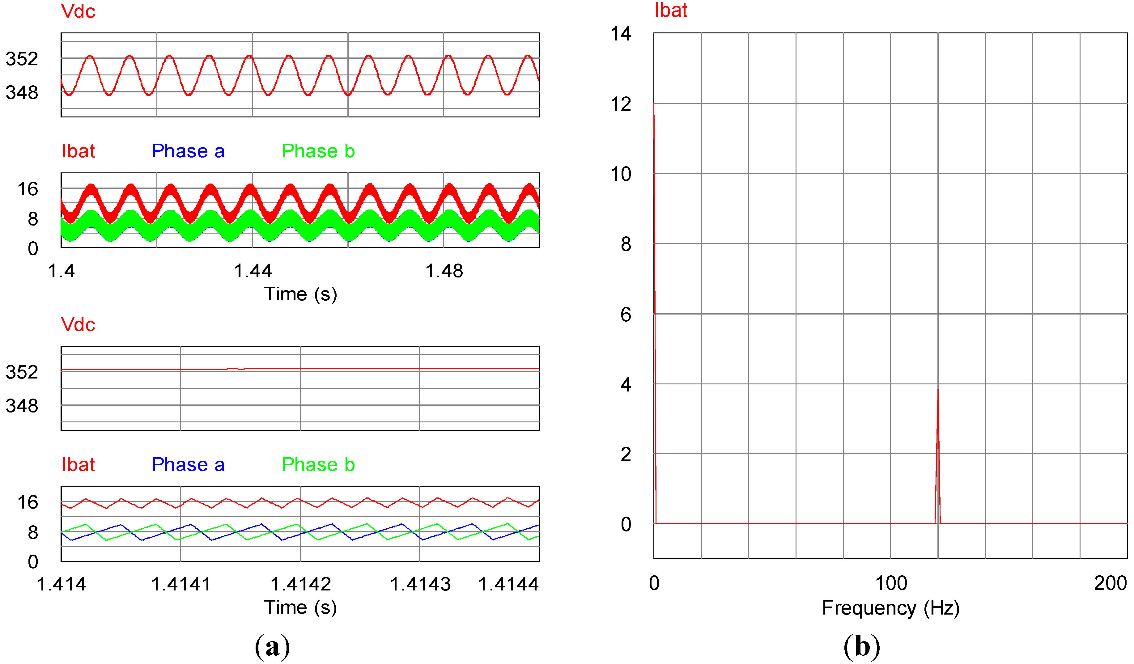
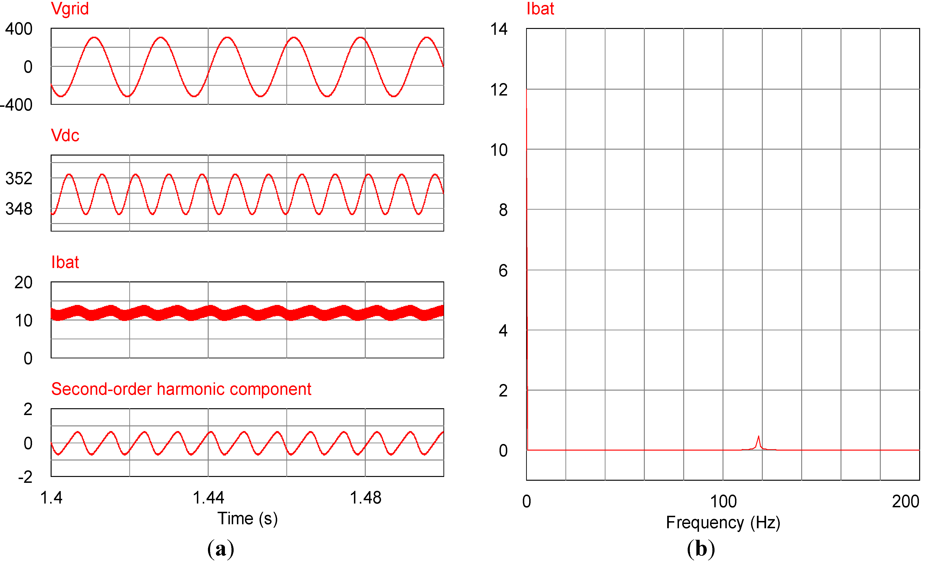
Figure 10a shows the characteristic operation before the addition of the compensation algorithm in the ESS. When the system operates to the charging mode, the DC/AC inverter controls the DC-link voltage to 350 V and transfers the power to the DC/DC converter. At this time, the DC-link voltage has ripples at 120 Hz caused by the pulsating power. The magnitude of the DC-link voltage ripple is approximately 2.3 A, therefore, the current of the battery oscillates around peak-to-peak 8 A as shown in
Figure 10a.
Figure10a shows the characteristics of the interleaved topology. The battery current is distributed to the interleaved current. The reference of the interleaved current is half of the reference of the battery current. The average value becomes the reference value because the interleaved current has a triangle shape due to the inductor. The average of the battery current is two times larger than that of the interleaved current as shown in
Figure 10a. The interleaved current has the same shape but a different phase by 180 degrees. The current is independently controlled in each phase.
Figure 10b shows the second-order harmonic component of the battery current at the frequency domain. The battery current has a second-order harmonic component because of the grid power oscillation at twice the grid frequency. The magnitude of second-order harmonic is approximately 4 A, as shown in
Figure 10b.
Figure 10.
Simulation waveform before the harmonic compensation. (a) DC-link voltage and battery current in time domain; (b) Battery current in frequency domain.
Figure 10.
Simulation waveform before the harmonic compensation. (a) DC-link voltage and battery current in time domain; (b) Battery current in frequency domain.
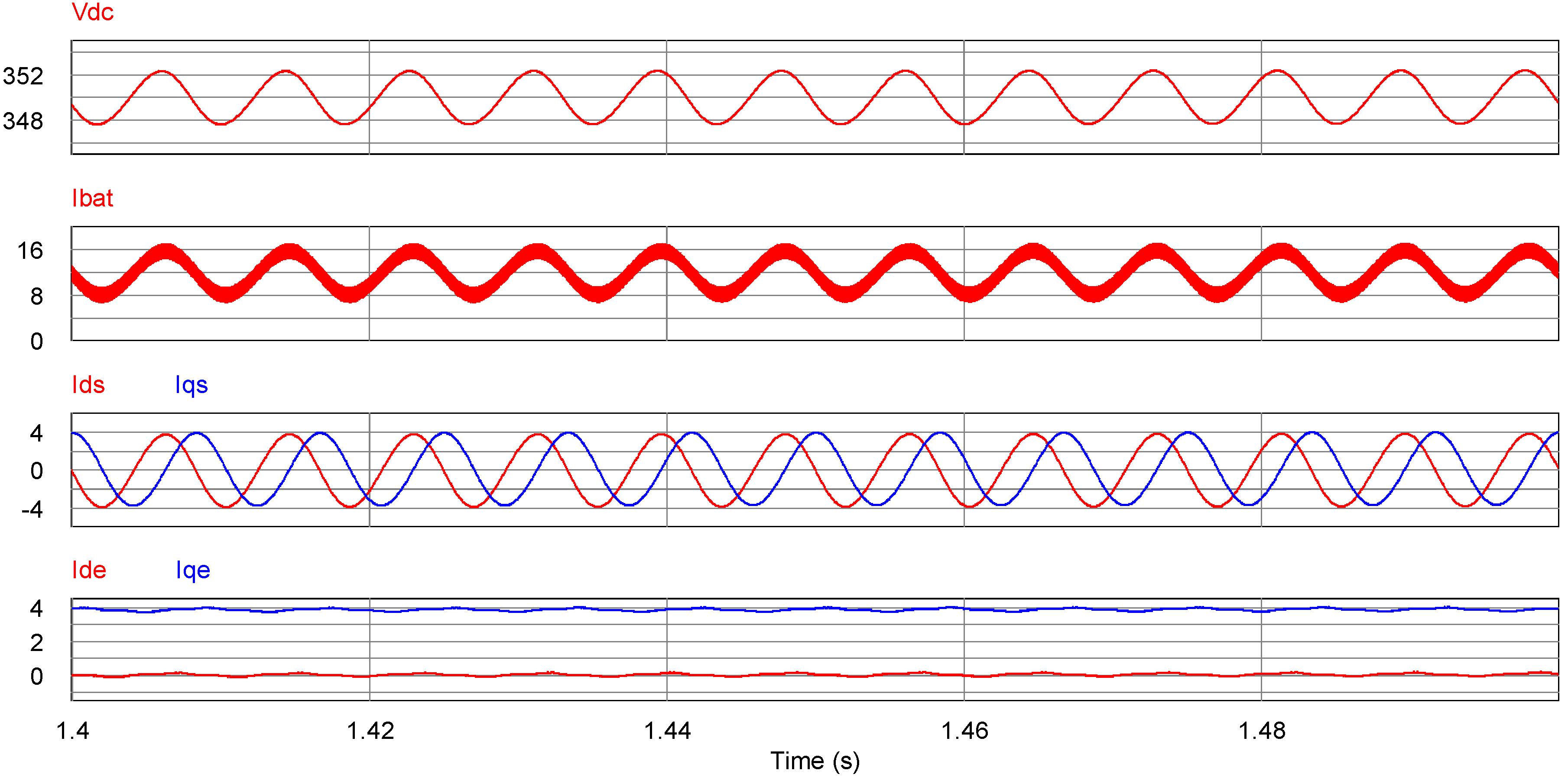
Figure 11 shows the method which extracts the second-order harmonic of the proposed algorithm under the same conditions as
Figure 10.
Ids becomes the second-order harmonic from the difference between the battery current and the reference current. The peak value of
Ids is approximately 4 A.
Iqs is created by using the APF. The
Iqs has the same magnitude and frequency of
Ids but the phase is shifted by 90 degrees. In order to use the PI controller, the second-order harmonic component is transferred to the synchronous reference frame. Under this condition, the phase angle of the grid voltage is used in the synchronous reference frame.
Iqe which has the magnitude of the second-order harmonic is 4 A and
Iqe is near zero.
Figure 11.
Extraction harmonics of the proposed algorithms.
Figure 11.
Extraction harmonics of the proposed algorithms.
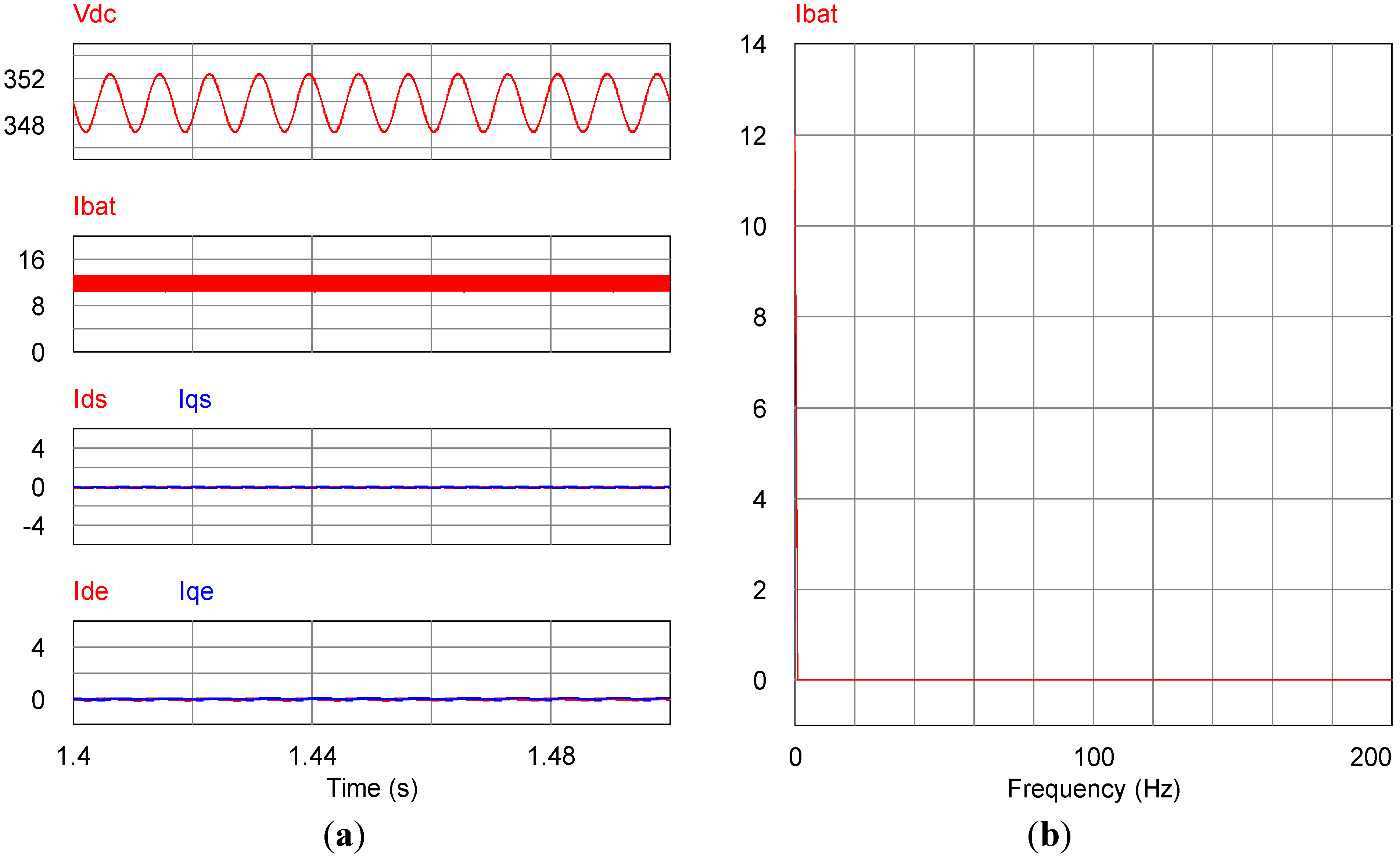
Figure 12a shows the performance of the proposed harmonic reduction algorithm. The DC-link voltage is controlled to an average of 350 V. However, the DC-link voltage has a 120 Hz ripple. The magnitude of the DC-link voltage ripple is approximately 2.5 A. The battery current is modulated by the DC-link voltage. If the second-order harmonic of the battery current is reduced, the power which is made by the battery current ripple is decrease.
Figure 12.
Simulation waveform with the PI compensation. (a) DC-link voltage and battery current in time domain; (b) Battery current in frequency domain.
Figure 12.
Simulation waveform with the PI compensation. (a) DC-link voltage and battery current in time domain; (b) Battery current in frequency domain.
The ripple of the DC-link is increase because the ripple power is reduced. When
Figure 12a is compared with
Figure 11a, the DC-link ripple is increase 0.2 A. The DC-link voltage variation is small because the capacitor of the DC-link is relatively large. The second-order harmonic of the battery current is reduced by applying the proposed algorithms. The battery current is controlled to an average of 12 A. However, the switching ripple still remains to the peak-to-peak of 2 A.
Ids is reduced to zero because the proposed algorithms compensate the second-order harmonic. Therefore, the magnitude of the second-order harmonic,
Iqe, is controlled to zero. The result of the proposed algorithm shows that the second-order harmonic component is sufficiently reduced as shown in
Figure 12b.
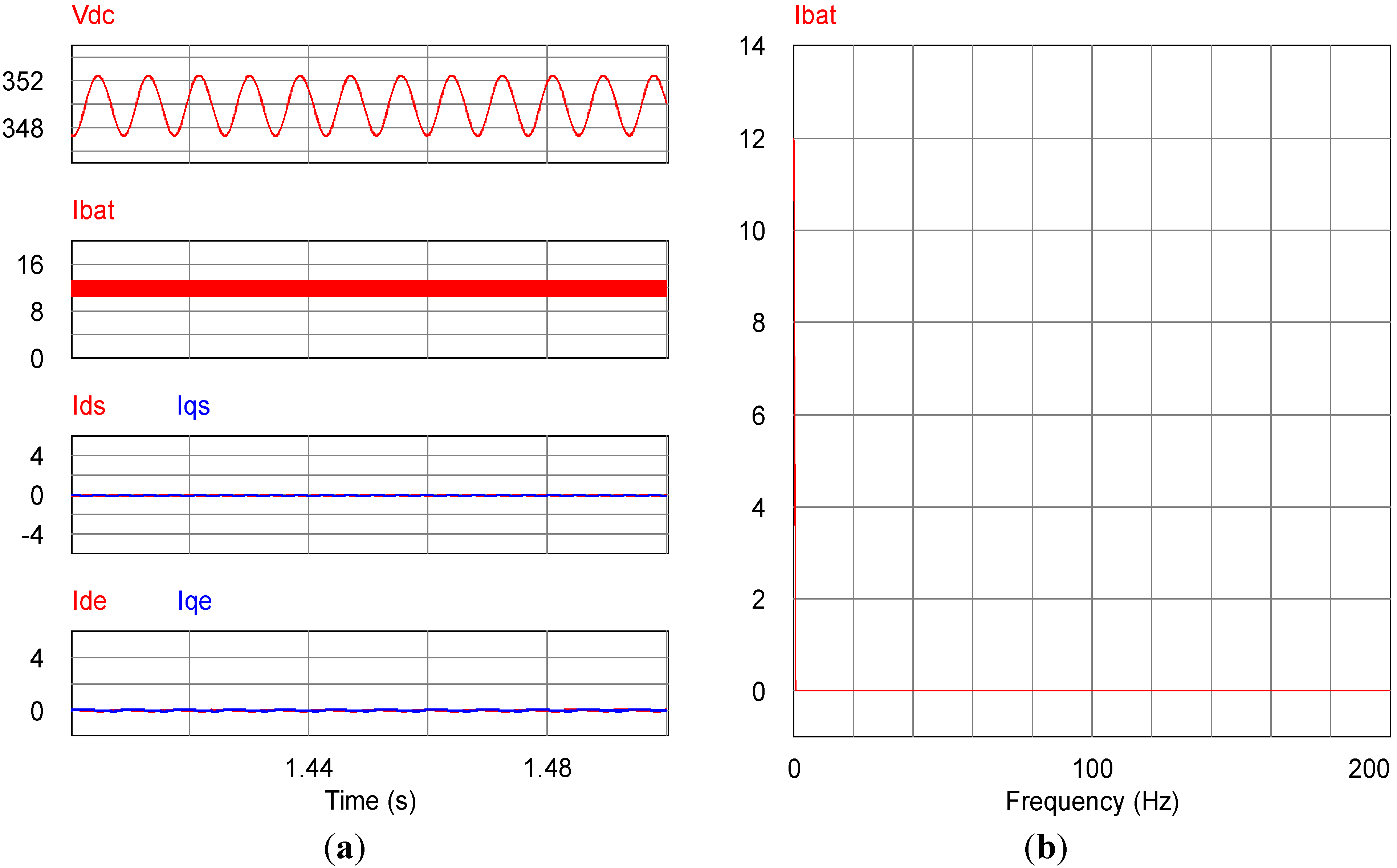
Figure 13 shows the current of the battery with the frequency variation from 60 Hz to 59 Hz when the compensation algorithm using the PR controller is added. The PR controller is suitable for the constant frequency operation because the PR controller has the narrow bandwidth in the middle of the resonant frequency. The resonant frequency of the PR controller is designed to be 120 Hz which is at twice the frequency of the grid. However, the frequency of the second-order harmonic is changed to 118 Hz under the conditions above. The PR controller cannot sufficiently extract and reduce the changed harmonic component due to the characteristic of the narrow bandwidth. Under this condition, the current ripple remains at a peak-to-peak value of 1.2 A as shown in
Figure 13a. The result of the compensation using the PR controller shows that the second-order harmonic component remains at 0.6 A as shown in
Figure 13b.
Figure 13.
Simulation waveform with the PR compensation. (a) DC-link voltage and battery current in time domain; (b) Battery current in frequency domain.
Figure 13.
Simulation waveform with the PR compensation. (a) DC-link voltage and battery current in time domain; (b) Battery current in frequency domain.
Figure 14 shows the performance of the proposed compensation technique under the same conditions as
Figure 13. The ripple component of the battery current is extracted by the same method shown in
Figure 11. The dq axis battery current is affected by the phase angle because the phase angle is used in the synchronous reference frame. Although the frequency is changed, the phase angle is estimated instantaneously by the PLL. Therefore,
Ide becomes zero and
Iqe becomes the magnitude of the ripple component. From the dq axis battery current, the PI controller reduces the ripple component to zero, as shown in
Figure 14a. The proposed harmonic compensation algorithm sufficiently reduces the second-order harmonic as shown in
Figure 14b.
Figure 14.
Simulation waveform with the PI compensation. (a) DC-link voltage and battery current in time domain; (b) Battery current in frequency domain.
Figure 14.
Simulation waveform with the PI compensation. (a) DC-link voltage and battery current in time domain; (b) Battery current in frequency domain.
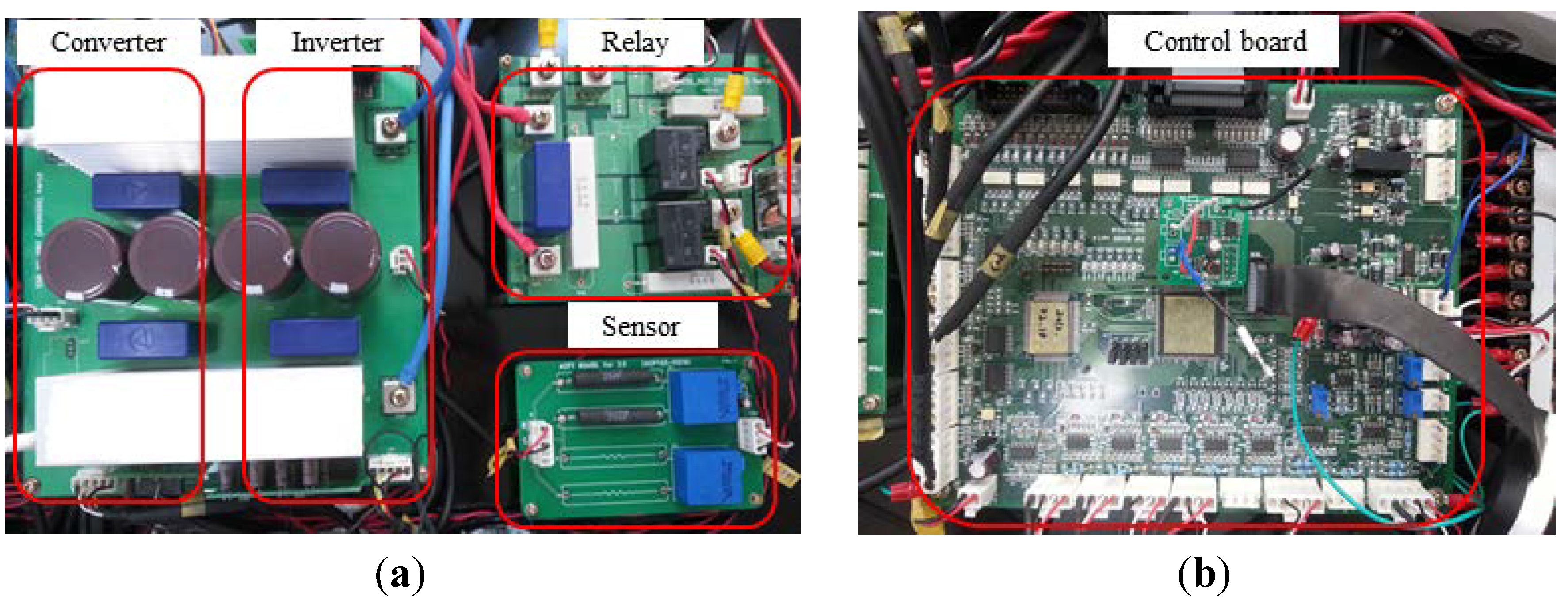
4. Experimental Section
Figure 15 shows the experimental set. The DC/AC inverter is the single-phase system as shown in
Figure 15a. The DC/DC converter consists of two inductors due to the interleaved topology.
Figure 15.
Experimental set: (a) Inverter and Converter; (b) Control board.
Figure 15.
Experimental set: (a) Inverter and Converter; (b) Control board.
Each control board is separated, because the inverter and converter are operated independently from each other. The proposed algorithm is programmed on a TMS320F28335 digital signal processor (DSP). The experiment is operated under the conditions given in
Table 2.
Table 2.
Experimental conditions.
Table 2.
Experimental conditions.
| Condition | Value | Unit |
|---|
| Rated power | 3 | kW |
| Grid side voltage | 220 | Vrms |
| DC-link voltage | 350 | V |
| Battery voltage | 250 | V |
| Battery-side current | 12 | A |
| Grid frequency | 60 | Hz |
| Grid-side inductor | 3 | mH |
| Grid-side switch frequency | 17 | kHz |
| DC-link capacitor | 4080 | μH |
| Battery-side inductor | 1 | mH |
| Battery-side switch frequency | 17 | kHz |
| Switch device | F4-50R06W1E3 by Infineon | - |
| Battery | Li-ion | - |
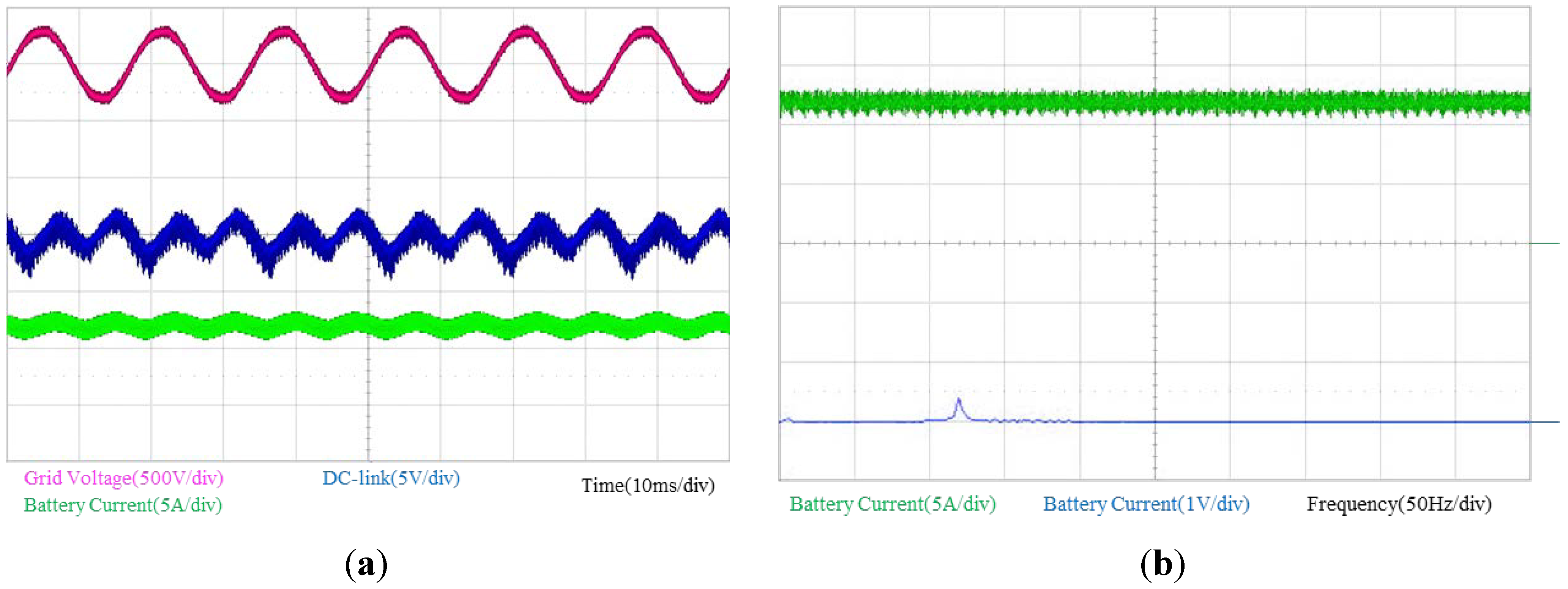
Figure 16 shows the experimental waveform without the second-order harmonic compensation under the rated conditions. Under these conditions, the system is connected to the grid which has a peak value of 311 V, and the ESS operates in the charging mode. The DC/DC converter regulates the output current to 12 A and the DC/AC inverter controls the DC-link to 350 V under this condition.
Figure 16.
Experimental waveform without the second-order compensation. (a) Time domain; (b) Frequency domain.
Figure 16.
Experimental waveform without the second-order compensation. (a) Time domain; (b) Frequency domain.
The DC-link voltage includes a 2 V ripple component as shown in
Figure 16a. In
Figure 16a, the current of the battery is pulsating at twice the grid frequency due to the DC-link voltage oscillation. The battery current is 12 A with a current ripple of ±0.8 A (7%).
In
Figure 16a, the ripple component in the synchronous reference frame (
iqe) has the DC offset and 120 Hz oscillation. The DC offset means the ripple reference and actual value of the battery current. This error does not affect the performance of the proposed compensator because the PI controller of the proposed compensator has a narrow bandwidth.
Figure 16b shows the battery current in the time and frequency domains.
The waveform represents the current of the battery pulsating at 120 Hz in the time domain and the magnitude of the 120 Hz component is approximately 0.8 A, which is included in the frequency domain.
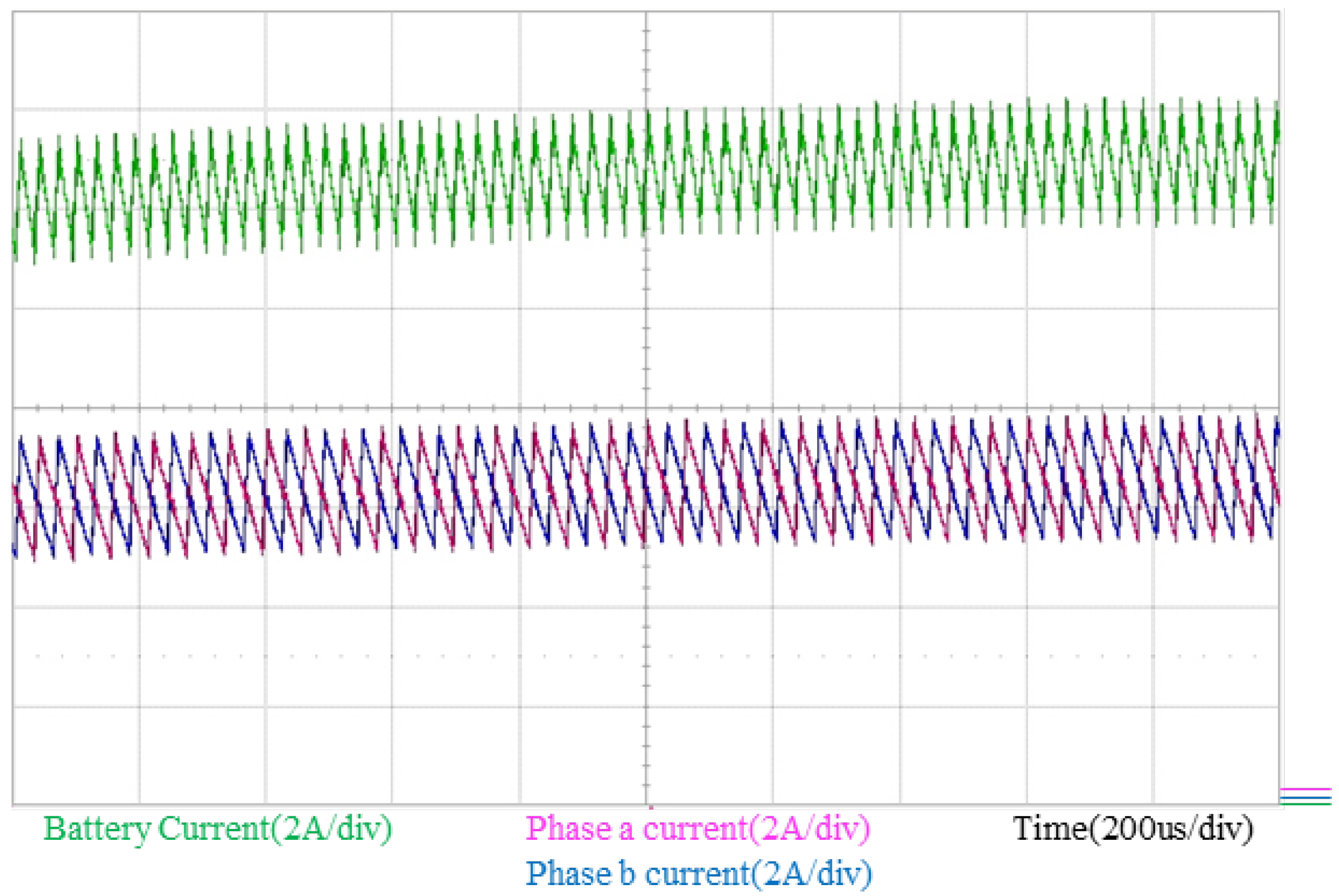
Figure 17 shows the battery current and interleaved current in the interleaved topology. The sum of the interleaved current is the same as the battery current in the interleaved converter. The interleaved current has the DC offset and ripple component. The DC offset is the average value and the ripple component is generated by the inductors of the converter. When the interleaved current is independently controlled, the average value is the same as the reference current which half the magnitude of the reference battery current.
Figure 17.
Battery current and interleaved current in time domain.
Figure 17.
Battery current and interleaved current in time domain.
Figure 18 shows the experimental waveform with the second-order harmonic compensation using the PR controller under the variable frequency condition. The grid frequency is changed from 60 Hz to 59 Hz. When compared to the waveform without the compensation, the ripple of the battery current is small. However, the waveform shows that the current of the battery is still pulsating at twice the grid frequency. After the grid frequency is changed, the PR controller cannot sufficiently extract exactly 118 Hz because the resonant frequency is designed to be 120 Hz. For this reason, the harmonic compensator using the PR controller clearly cannot reduce the second-order harmonic. The magnitude of the second-order harmonic component remains to be peak-to-peak 0.8 A.
Figure 18b shows the battery current in the time and frequency domains. The waveform shows that the second-order harmonic component is approximately 0.4 A.
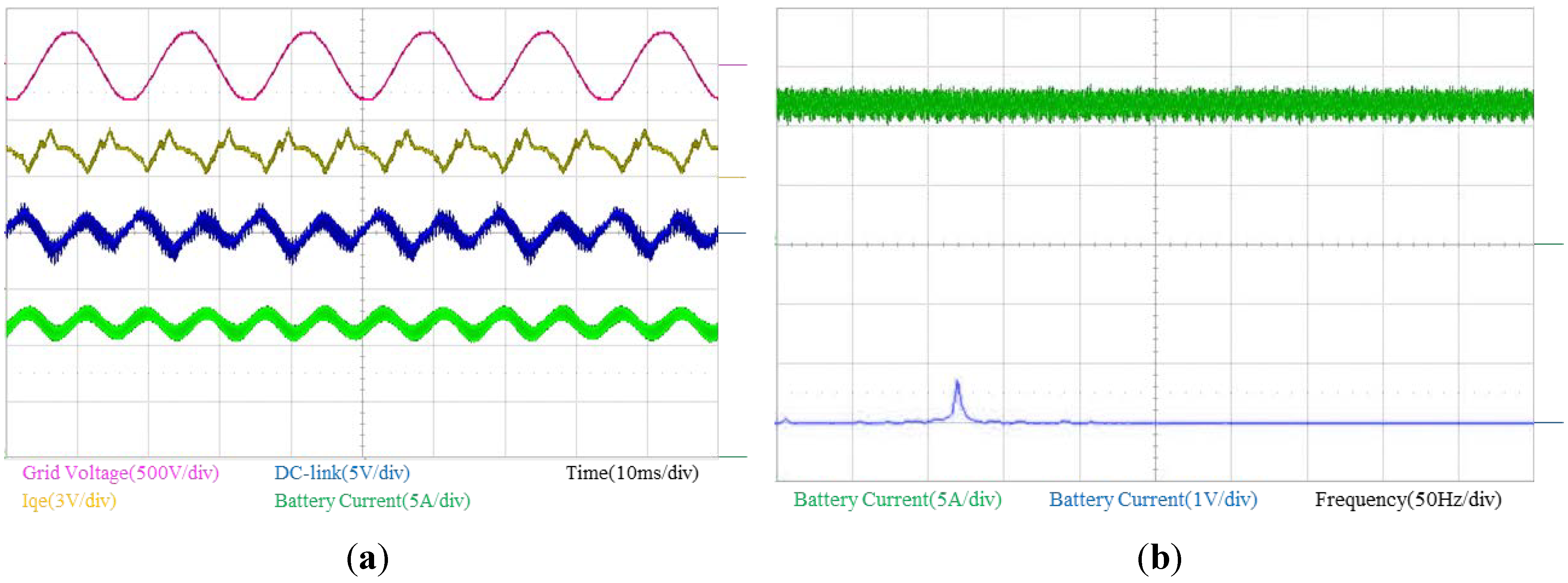
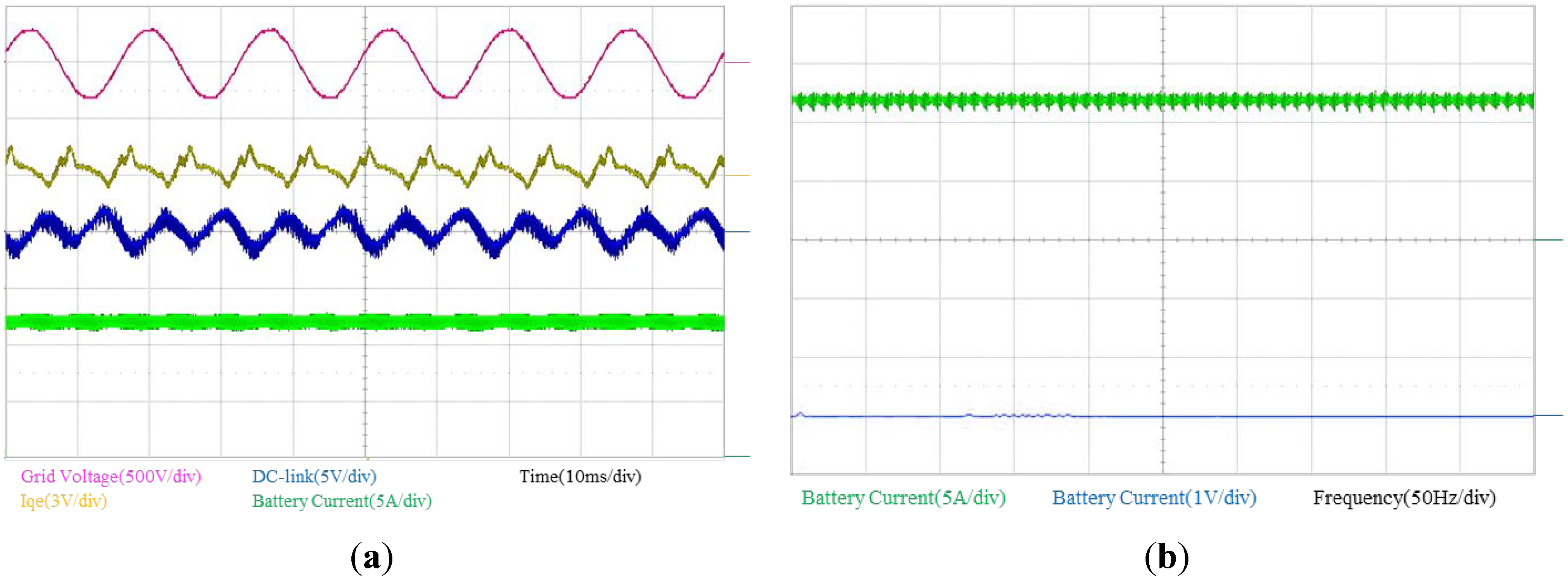
The performance of the proposed second-order harmonic reduction algorithms using the PI controller applied under the same conditions as in
Figure 18 is shown in
Figure 19. The proposed compensator has not affected the grid voltage and the DC-link voltage as shown in
Figure 19a. The DC-link voltage is controlled to 350 V but is still pulsating at the twice the grid frequency by the oscillation of the grid power. When compared to the waveform without the compensation in
Figure 16a, the DC component of
Iqe becomes smaller because the harmonic compensator has controlled
Iqe to a value of zero.
The
Iqe is still pulsating due to other harmonics but the average value of
Iqe is close to zero. The DC component of
Iqe is affected by the phase angle. The DC component of
Iqe becomes the magnitude of the ripple component because the phase angle is instantaneously estimated by the PLL under the frequency variable condition.
Figure 19b shows that the second order harmonic has been almost eliminated by the proposed compensator. The battery current seems to be composed only of the DC component. The ripple component of the battery is completely reduced to zero.
Figure 18.
Experimental waveform with PR compensation. (a) Time domain; (b) Frequency domain.
Figure 18.
Experimental waveform with PR compensation. (a) Time domain; (b) Frequency domain.
Figure 19.
Experimental waveform with PI compensation: (a) Time domain; (b) Frequency domain.
Figure 19.
Experimental waveform with PI compensation: (a) Time domain; (b) Frequency domain.


