1. Introduction
Hybrid electric vehicles (HEVs) have received much attention in view of their low emissions and high fuel economy. The first commercially available HEV, the Toyota Prius, was marketed in 1997, and utilizes a planetary gear and two electrical machines to fulfill the power-split function. The planetary-gear power-split system has proven to be a successful configuration, but the planetary gear, as a mechanical device, inevitably causes problems of transmission loss, gear noise, and it needs regular lubrication. Therefore, compound-structure machines have been explored to replace the planetary-gear power-split system [
1,
2].
Among them, the compound-structure permanent-magnet synchronous machine (CS-PMSM) has been widely investigated, demonstrating the ability to be an alternative to the planetary gear [
3]. The CS-PMSM employs two electrical machines to take full control of the output torque and speed of the internal combustion engine (ICE). By adopting a suitable control strategy, the CS-PMSM can make the ICE operate at optimum efficiency almost independent of road conditions, thus maximizing the system efficiency [
4]. However, the CS-PMSM has brushes and slips, leading to the disadvantages of friction losses, high maintenance, need for cooling and so on. As a consequence, new brushless compound-structure machines are being developed to avoid the shortcomings of the CS-PMSM.
In this paper, a brushless compound-structure transverse-flux permanent-magnet synchronous machine (CS-TFPMSM) is proposed. The key component of the CS-TFPMSM is a brushless transverse-flux dual rotor machine (TFDRM) which originates from the principle of transverse-flux machines. The transverse-flux machine refers to the electrical machine that has a magnetic circuit which is perpendicular to the direction of current flow and rotor motion [
5].
Different from traditional machines, because the space occupied by the electrical and magnetic paths have no competition to each other, the transverse-flux machine can offer high power density and thus make the system smaller [
6], which is suitable for electric vehicle applications [
7]. The transverse-flux machine has some disadvantages though, such as a complicated structure with 3D magnetic circuit, high flux leakage, low power factor, difficult manufacture, and so on [
8]. To get rid of these problems, many transverse-flux machines topologies have been investigated. According to the different arrangements of phases, windings, and permanent magnets (PMs), the transverse-flux machine can be divided into several types: in-plane phases, axial-arranged phases; single-sided windings, double-sided windings; surface-mounted PMs, flux-concentration PMs; and so on [
9]. The flux-concentration mode has the particular distinguishing characteristic that the flux density from the PMs can be concentrated and strengthened, which is favorable for the torque density [
10,
11]. Therefore, the TFDRM design is based on the flux-concentration transverse-flux machine.
2. Brief Introduction of the CS-TFPMSM
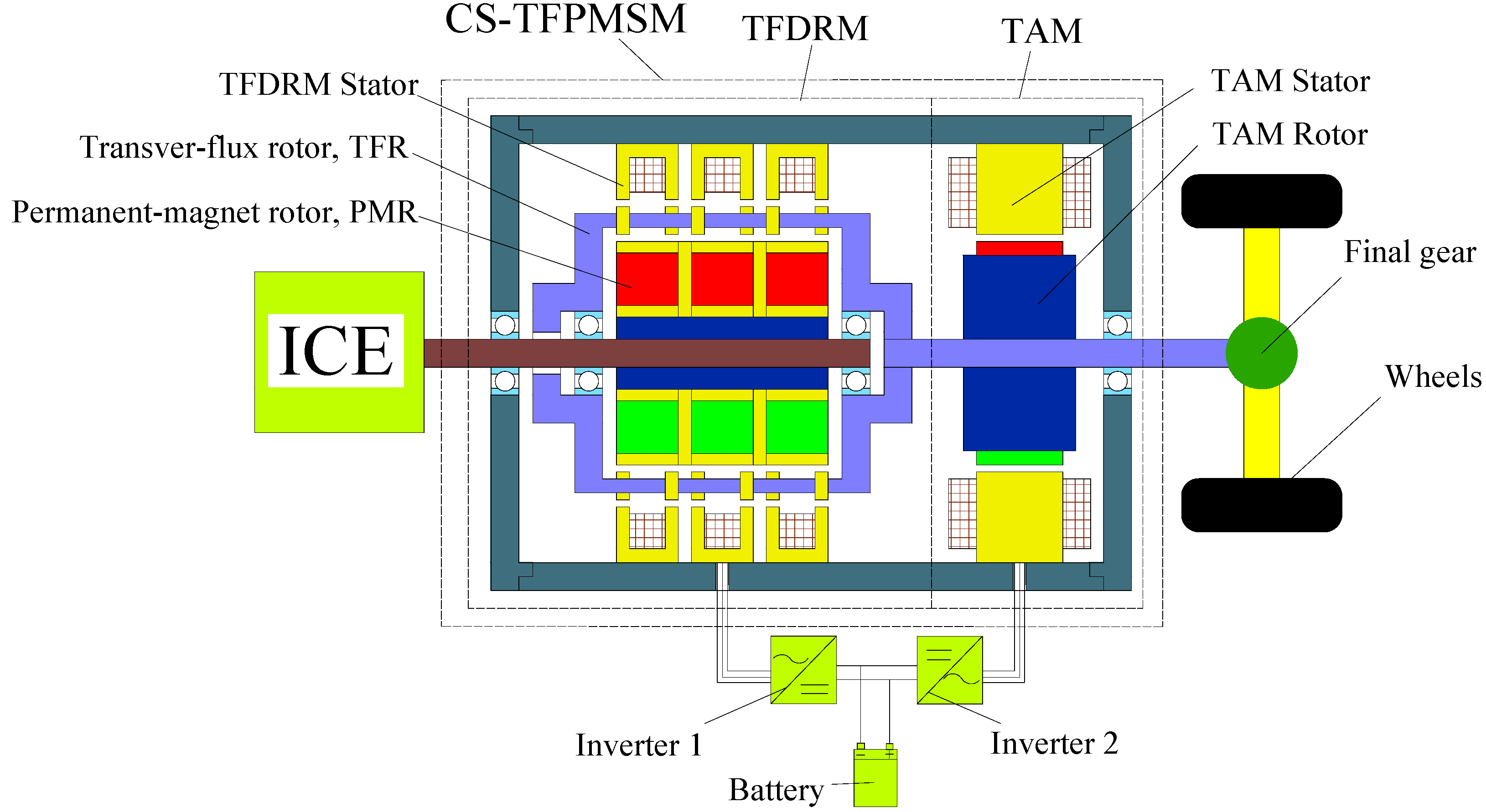
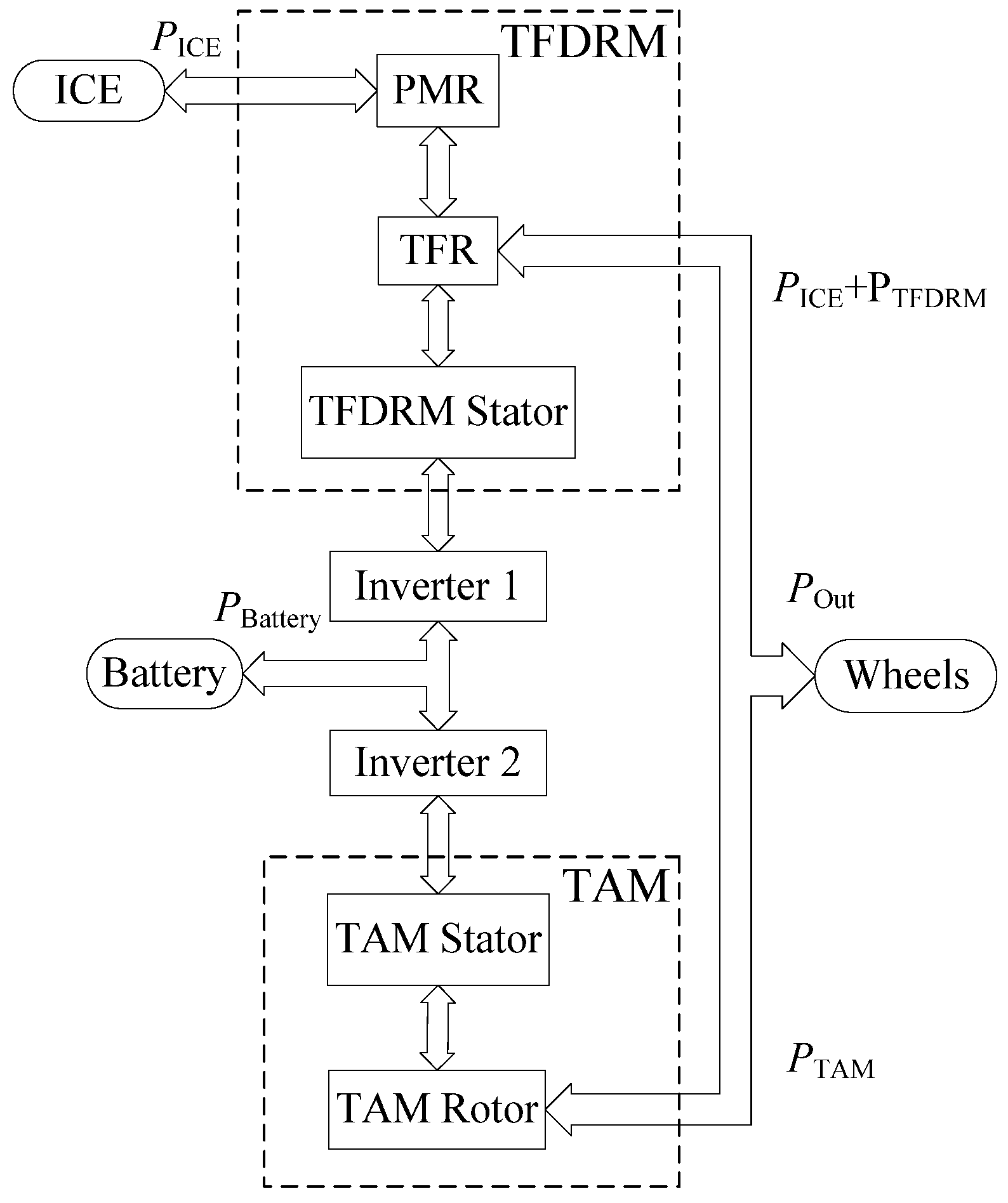
First of all, we introduce the schematic diagram of the CS-TFPMSM system. As shown in
Figure 1, this system is mainly formed by the CS-TFPMSM, two inverters, and the battery. It is placed between the ICE and wheels to realize the power-split function. The CS-TFPMSM has two axially arranged machines: a brushless transverse-flux dual rotor machine (TFDRM) and a torque-adjusting machine (TAM). The inner rotor (permanent-magnet rotor, PMR) of the TFDRM is directly connected to the ICE; and the outer rotor (transverse-flux rotor, TFR) of the TFDRM is connected to the rotor of the TAM and the wheels. The TFDRM is the part that possesses a transverse-flux structure, and the TAM is just a traditional PMSM. Like the transverse-flux machines, the TFDRM adopts the flux-concentration (FC) mode to arrange the PMs [
12].
Figure 1.
The CS-TFPMSM system.
Figure 1.
The CS-TFPMSM system.
During operation, the TFDRM changes the speed of the output shaft of the TFR relative to the ICE, and transfers the torque from the ICE to the TAM. The TAM supplies the difference of the torques between the ICE and the wheels. In this way, the CS-TFPMSM fulfills the control on both the speed and torque, and allows the ICE to operate at optimum efficiency points almost independent of road conditions, hereby decreasing emissions and improving fuel economy. The energy flow in the brushless CS-TFPMSM system is illustrated in
Figure 2.
Figure 2.
Energy flow in the CS-TFPMSM system.
Figure 2.
Energy flow in the CS-TFPMSM system.
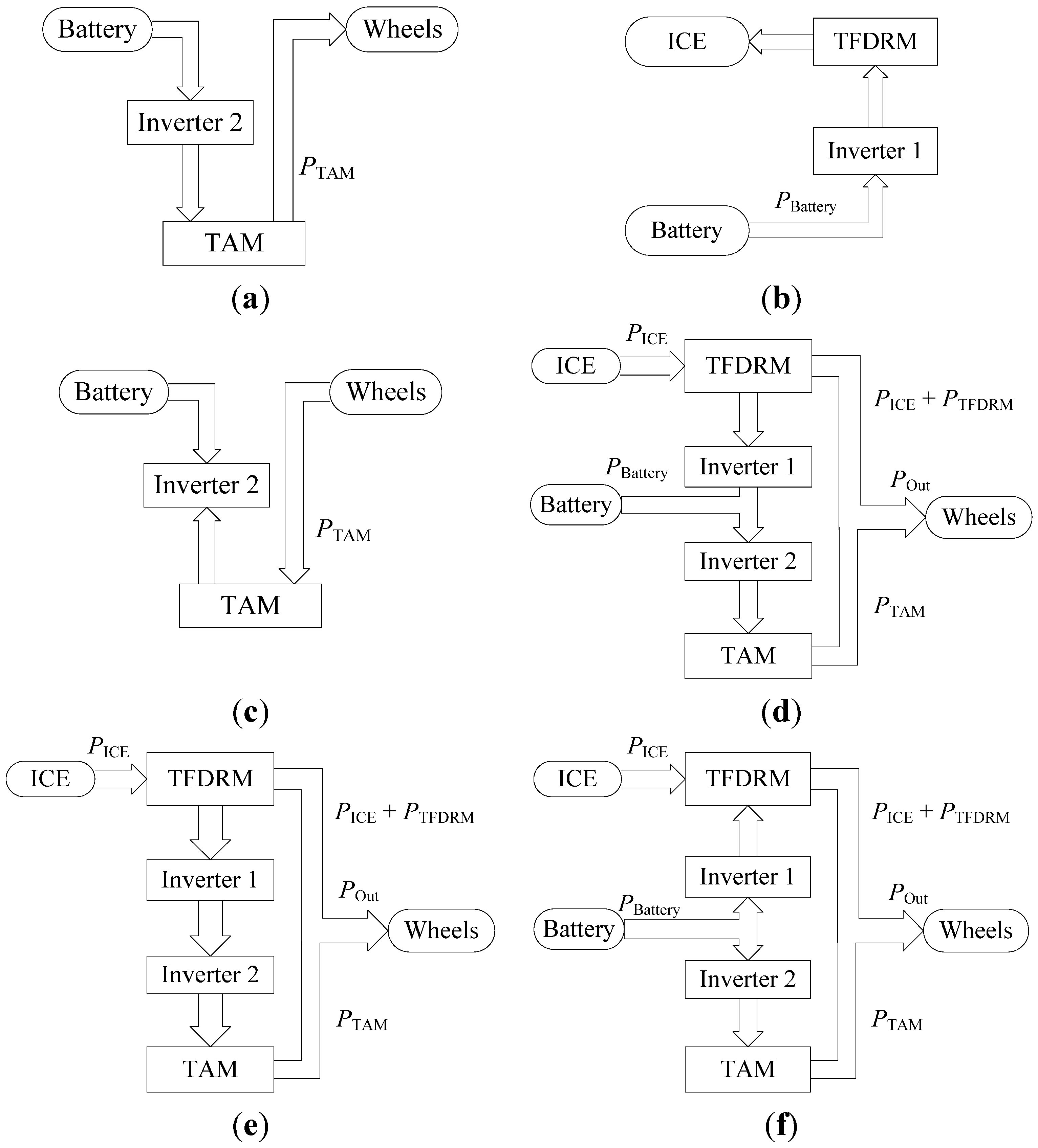
There are six typical operation states of this system, as shown in
Figure 3.
Figure 3a illustrates the pure electric mode, in which the vehicle wheels are simply driven by the TAM.
Figure 3b shows the ICE starter mode, in which only the TFDRM works.
Figure 3c shows the braking mode, in which the TAM operates as a generator to recover the brake energy.
Figure 3d shows a complex mode, hill-climbing mode. Because the requirement of wheels for torque is higher than the torque input from the ICE, the rest of the torque is provided by the TAM.
Figure 3e shows another complex mode, the continuously variable transmission (CVT) mode, in which the TFDRM generates electric power to supply the TAM, and the speed and torque of the ICE are adjusted by both TFDRM and TAM to meet the requirement of the wheels.
Figure 3f also shows a complex mode, acceleration mode, in which the battery provides the power through the CS-TFPMSM to satisfy the requirement of wheels for power.
Figure 3.
Typical operation states of the power-split hybrid drive system: (a) Pure electric mode; (b) ICE starter mode; (c) braking mode; (d) hill climbing mode; (e) CVT mode; (f) acceleration mode.
Figure 3.
Typical operation states of the power-split hybrid drive system: (a) Pure electric mode; (b) ICE starter mode; (c) braking mode; (d) hill climbing mode; (e) CVT mode; (f) acceleration mode.
To verify the power conversion, the relationship is derived as follows. In the TFDRM, the magnetic field generated by stator windings is modulated by the TFR and imposed on the PMR. Following the principle of the transverse-flux machines, there is a relative motion between the TFR and the PMR. The relationship between the speed of the TFR and the PMR is shown in Equation (1):
where Ω
TFR is the mechanical speed of the TFR (rad/s); Ω
PMR is the mechanical speed of the PMR (rad/s); ω
TFDRM is the angular frequency of the winding current in the TFDRM (rad/s);
pTFDRM is the pole-pair number of the TFDRM; ω
TAM is the angular frequency of the winding current in TAM (rad/s) and
pTAM is the pole-pair number of the TAM.
On the other hand, as for the output torque of the shaft, it comprises the torque of the TFDRM and the torque of the TAM:
where
TTFDRM is the torque of the TFDRM and
TTAM is the torque of the TAM which can be positive or negative depending on the difference between the demanded output torque and the torque generated by the ICE.
The output mechanical power is shown in Equation (3):
where
PTFDRM is the electromagnetic power of the TFDRM;
PTAM is the electromagnetic power of the TAM;
PBattery is the input power from the battery; and
PICE is the input mechanical power from the ICE.
In all, the TFDRM and the TAM of the brushless CS-TFPMSM are employed to adjust the differences of speed and torque between the ICE and the wheels. Without any brushes or planetary gears, both maintenance cost and mechanical cogging noise of the HEV system are greatly reduced. This advantage makes the CS-TFPMSM favorable for HEV applications.
3. Structure and Principle of the TFDRM
3.1. The Structure of the TFDRM
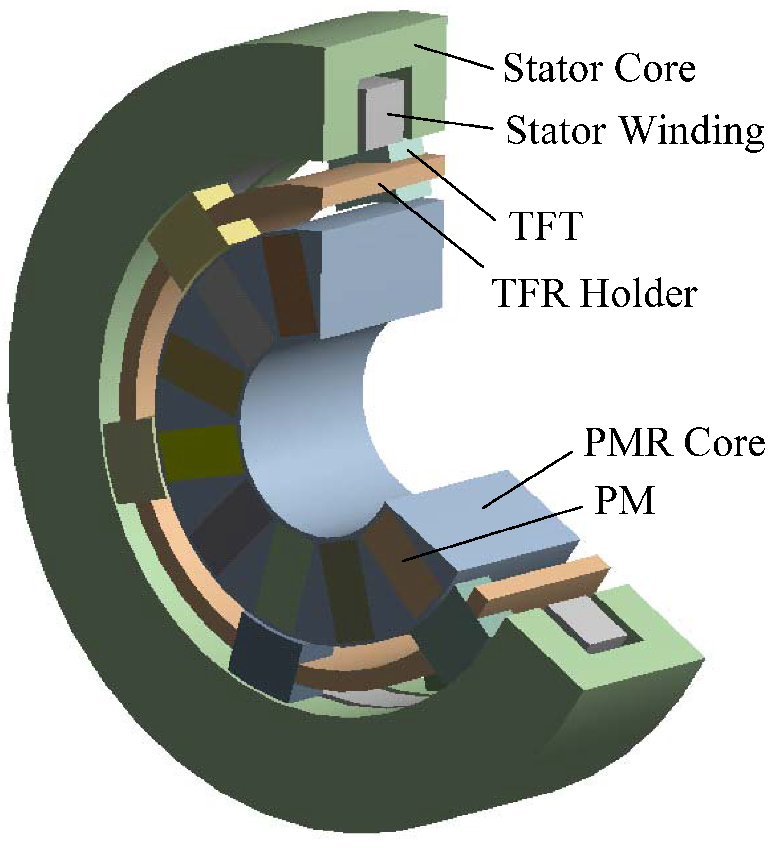
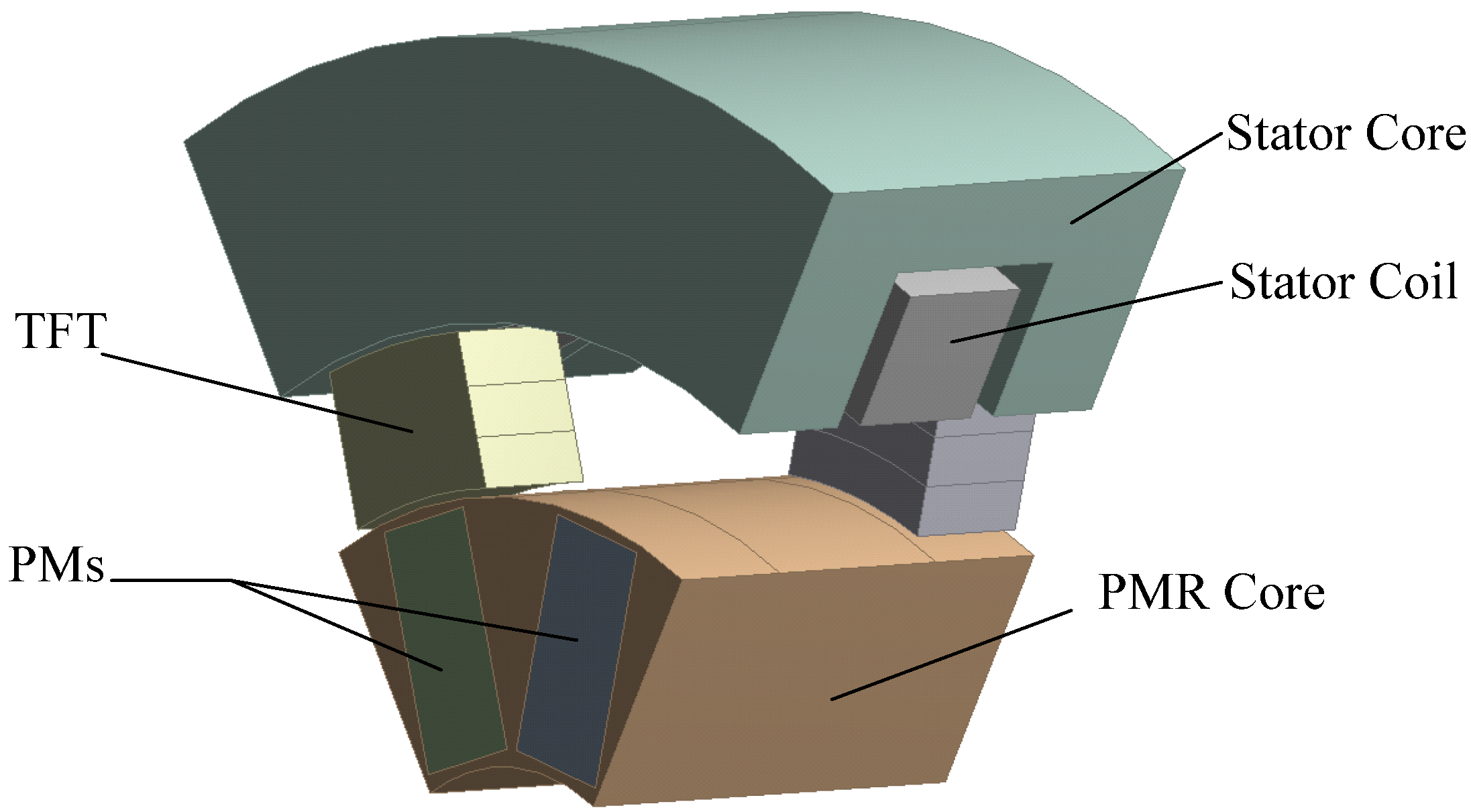
The TFDRM is the key component of the CS-TFPMSM, and originates from the transverse-flux machines. Like the axial three-phase transverse-flux machines, the TFDRM is actually made of three separate single phases. The three single phases of the TFDRM are axially stacked with a small gap between one another to decouple them magnetically and avoid flux leakage between phases. The electrical angle between two phases is 120°.
Figure 4 shows one phase of the 6-pole-pair TFDRM. Every phase consists of three parts radically arranged (from outside to inside): the stator, the TFR, and the PMR. There is an outer air gap between the stator and the TFR, and an inner air gap between the TFR and the PMR, too. Both the TFR and the PMR rotate peripherally. The stator core has a U-shaped cross section which contains a yoke and two endings. In the stator of every phase, there is a simple concentric toroidal armature winding, which is surrounded by the stator core.
Figure 4.
One phase of the TFDRM.
Figure 4.
One phase of the TFDRM.
Every phase has respectively corresponding transverse-flux teeth (TFT). The TFT of these three single phases are stacked in the axial direction, and are circumferentially shifted in space by 120/pTFDRM mechanical degrees (120 electrical degrees) to form a balanced three-phase topology. In one phase, the number of the TFT equals to the pole number. The TFT of one phase are equally distributed into two rows and fixed in a holder. To fit the arrangement of the permanent magnets in the FC mode, one row of the TFT should be circumferentially shifted by one pole pitch.
For every phase, there are also corresponding PMs in the PMR. The PMR of every phase is the same and located at an aligned position. In one phase, the number of the PMs also equals the pole number. Employing the FC mode, the magnets are circumferentially magnetized in an alternating way. In this setup, the steel parts between the successive opposite magnets of different polarity in the circumferential direction become the rotor poles. The FC mode utilizes all the magnets at any one time and this allows the flux density in the working air gap to increase significantly.
3.2. The Magnetic Circuit of the TFDRM
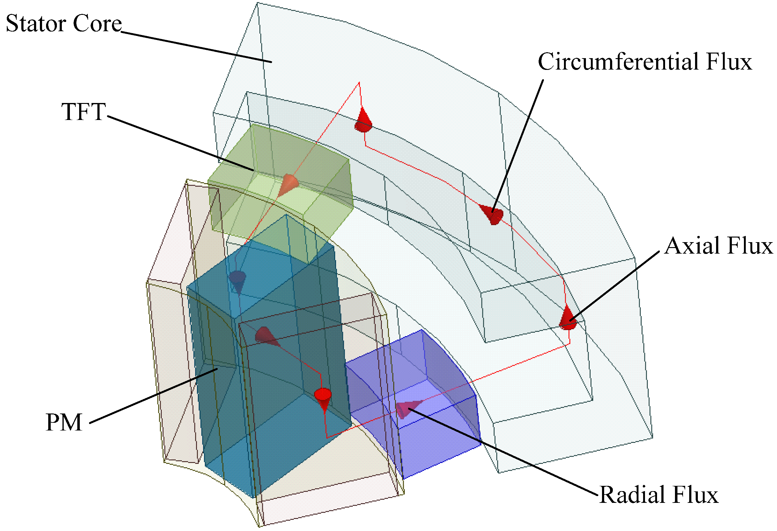
In every phase, the TFDRM has multiple flux loops magnetically coupled with the winding. Every flux loop is an integral element, going through the stator core, the TFT, the PMs and the PMR core. The magnetic circuit turns out to be quite a complex 3D path.
Figure 5 illustrates the magnetic flux path for a two-pole section of the TFDRM in detail. The arrows represent the flux directions. For clarity, the other loops, which go through other magnets and couple with the winding, are not illustrated in the figure.
From the analysis of the flux path, we can find that the total number of flux loops is proportional to the pole number. This number can be determined without competing with the axial length of the stator slot, because the space occupied by the flux-carrying core irons and the armature windings are independent of other. With the relative motion between the TFR and the PMR, the flux-change rate is proportional to the product of the pole number and the relative speed between rotors.
Figure 5.
Magnetic flux path for a two-pole section.
Figure 5.
Magnetic flux path for a two-pole section.
Under load, every phase of the stator windings of TFDRM actually excites an independent one-pole-pair MMF, which is just an alternating wave rather than a common rotating field. Through the outer air gap, the one-pole-pair MMF is transferred into the corresponding TFT and transformed into a multi-pole-pair magnetic field. The interaction between the multi-pole-pair field in the inner air gap and the poles on the PMR will generate a torque. The torque of three phases is combined into a continuous effective torque leading to the difference between speeds of the TFR and the PMR.
From the former analysis on the magnetic circuit, we can see that the TFDRM actually possesses a magnetic circuit similar to the transverse-flux machines; and the brushes are eliminated through the shift of the structure of the transverse-flux machines.
Considered from another aspect, the TFDRM is developed from the transverse-flux machine in this way: the teeth of a transverse-flux machine are cut down and fixed in a holder to form the TFR; based on the remainder, a new stator is formed; and the PMR remains unchanged. Separation of the teeth from the stator of a transverse-flux machine produces a brushless dual rotor motor, with the principle of the transverse-flux machine unchanged.
In the aspect of manufacturing, the TFDRM also possesses some advantages: (1) the stator windings have a simple shape to manufacture and (2) a high slot fill factor can be achieved, so the space in the TFDRM can be used effectively.
4. Characteristics of the TFDRM
4.1. Torque Equations of the TFDRM
To dimension the size of the TFDRM, the electric and magnetic loads are first determined in an analytical way. Although the concept of electric load remains available for the circular armature windings of the TFDRM, the general definition of electric load cannot properly reflect the real status that the windings are embedded in the inner surface of the stator of the TFDRM. So the electric load of the TFDRMs is redefined as the total ampere-turns per axial armature length:
where
lef is the effective axial length of a single phase of the TFDRM;
N is the number of the stator-winding turns;
I is its current value.
The equation of the magnetic flux should be written as:
where
p is the pole-pair number;
D1 is the inner diameter of the TFR; σ
1 is the leakage factor of the flux from the outer air gap into the stator core; σ
2 is the leakage factor of the flux from the inner air gap into the PMR; Φ
1 is the magnetic flux in the inner air gap, α’
p is the effective pole arc coefficient; and
Bδ2 is the maximum flux density in the inner air gap.
As a result, the power equation of the TFDRM is derived as follows:
and the new torque density equation of the TFDRM is as follows:
where
m is the phase number;
n is the synchronous speed;
D0 is the outer diameter of the stator; ψ is the leading phase angle of the armature current
I relative to
E and
KΦ is the waveform factor of the magnetic flux.
From the equations above, we can find that the torque density of the TFDRM is proportional to the product of flux density
B, which is the same as in the traditional PMSMs. As a result, the structure which can enhance the flux density
B is favorable, for example, the FC mode [
13].
The torque density of the TFDRM is also proportional to the pole-pair number, which is different from the traditional PMSMs. The reason is that the increase of the pole-pair number of the TFDRM results in a corresponding increase in the electrical frequency. On the other hand, the magnetic flux remains unchanged when the number of pole pairs is simply increased. The electric load also remains unchanged, because the increase of the pole-pair number has no impact on the available area of the stator slot. Consequently, there is an increase in the torque density.
As a result, in the design process, increasing the pole-pair number is a direct way to obtain a high power density, but there is a limitation in that the increase of pole-pair number can also probably increase the magnetic flux leakage among the TFT.
As a dual rotor machine, the TFDRM processes one more leakage factor σ2. The existence of the parameter σ2 increases the magnetic resistance of the main magnetic circuit, resulting in more flux leakage and a lower power factor. As a result, adopting a short air gap is favorable, but the length of the air gap is still limited by the level of processing technique.
4.2. Power Factor Analysis of the TFDRM
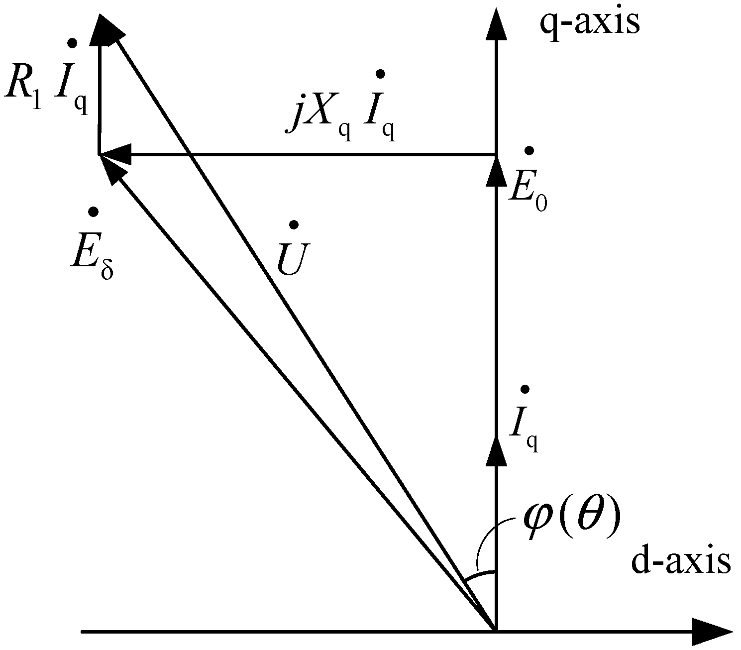
Like transverse-flux machines, the TFDRM tends to have a low power factor at high load. The characteristics of the TFDRM can be described and analyzed using a phasor diagram, the same as the traditional synchronous machines [
14]. When the TFDRM is only fed with a current in the q-axis, and the d-axis armature current
Id = 0, the relationship of electromagnetic parameters is shown in
Figure 6.
Iq is the q-axis armature current.
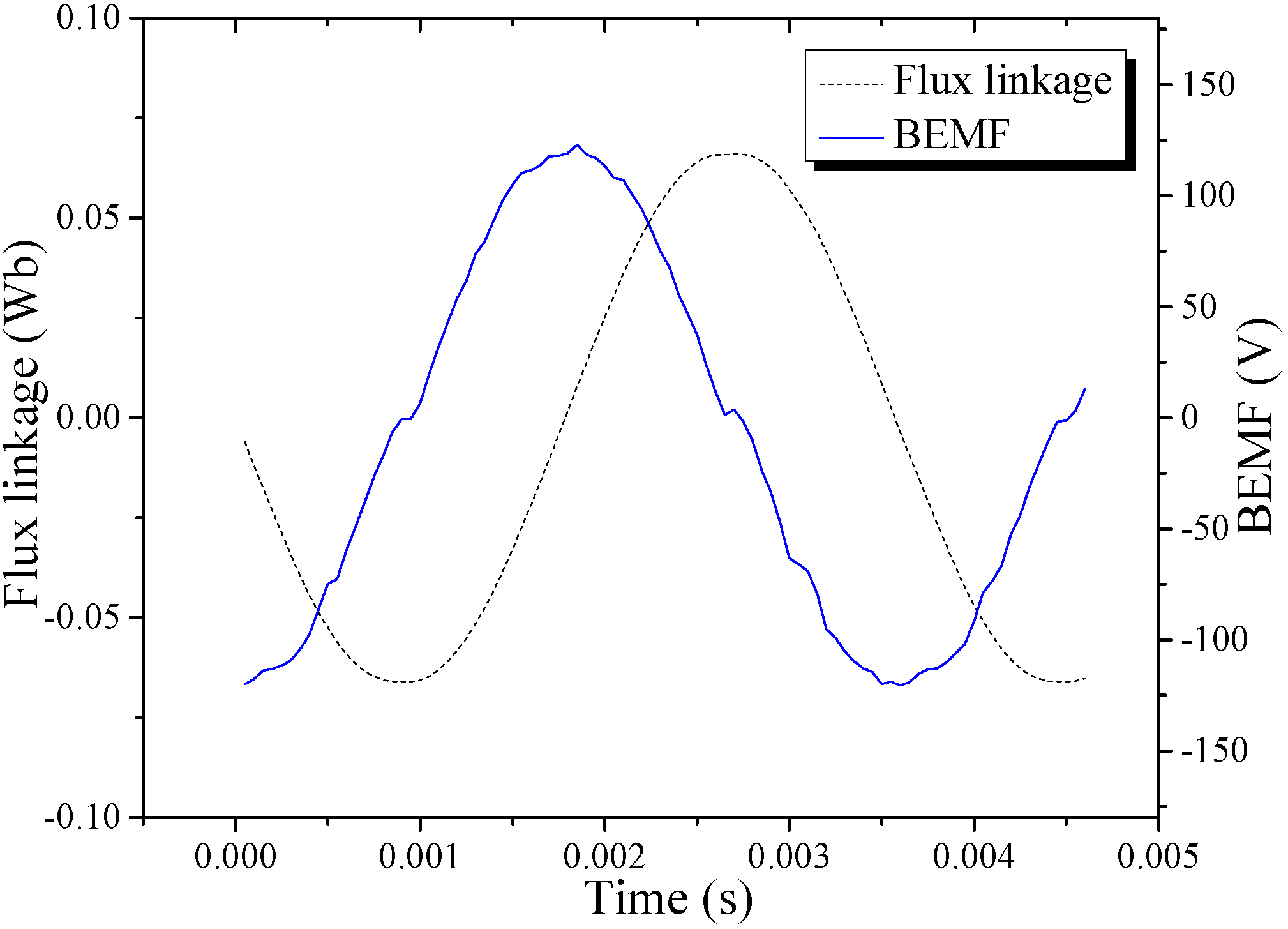
E0 and
Eδ are respectively the back electromotive forces (BEMFs) at the conditions of no-load and load, and
U is the voltage fed by the external circuit.
R1 is the armature resistance, and
Xq is the q-axis reactance. φ is the power factor angle, and θ is the torque angle.
Figure 6.
Phasor diagram when Id = 0.
Figure 6.
Phasor diagram when Id = 0.
With the small voltage drop across the phase resistance neglected, the power factor is expressed as:
and if unsaturated:
where Φ
m is the effective PM flux that links the stator winding and Φ
i is only the magnetic flux induced by the armature current.
From Equation (10), we know that increase the permanent magnetic flux Φm is favorable to improve the power factor. In the design stage, adopting some certain structures, for example, the FC mode, the magnetic flux density generated by permanent magnets that can be enhanced significantly. The FC mode is also beneficial to enhance the torque density, but the permanent magnets increase will lead to a high cost of materials, which makes this unattractive in practice.
Different from traditional machines and common transverse-flux machines, the TFDRM possesses two layers of air gaps. The two layers of air gaps could dramatically increase the reluctance of main magnetic circuit, and decrease magnetic flux Φm. Reduction of magnetic flux Φm will decrease the power factor. On the other hand, in the magnetic circuit of TFDRM, there is inherently a serious leakage flux due to the special transverse-flux configuration. The high leakage flux of the TFDRM also influences the power factor heavily. The enhancement of the reluctance of main magnetic circuit will increase the possibility of leakage flux. As a result, the two layers of air gaps make the problem of power factor much worse than common transverse-flux machines. Obviously, short length of outer/inner air gap is very important for increasing magnetic flux Φm and improving the power factor. But decreasing the length of outer/inner air gap is limited by the difficulty of manufacture. Finally, a compromise has to be done.
The equation can be further transformed into the following form:
where
Xd and
Xq are the d- and q-axis synchronous reactance. And
Id =
I·sinψ,
Iq =
I·cosψ.
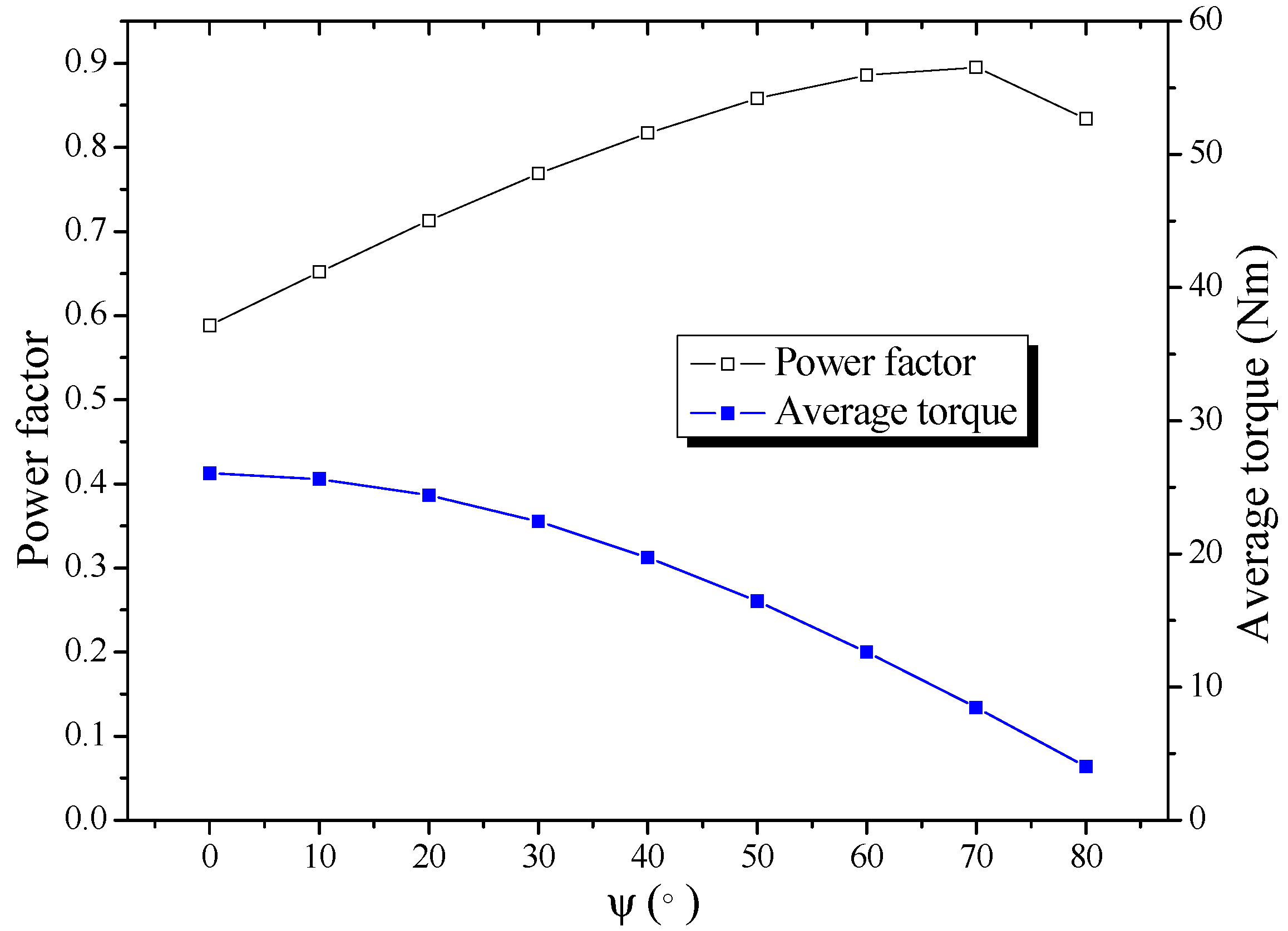
In the control of the TFDRM, there is also an effective way to improve the power factor by altering ψ, which is the leading phase angle of the armature current
I relative to
E0. As shown in
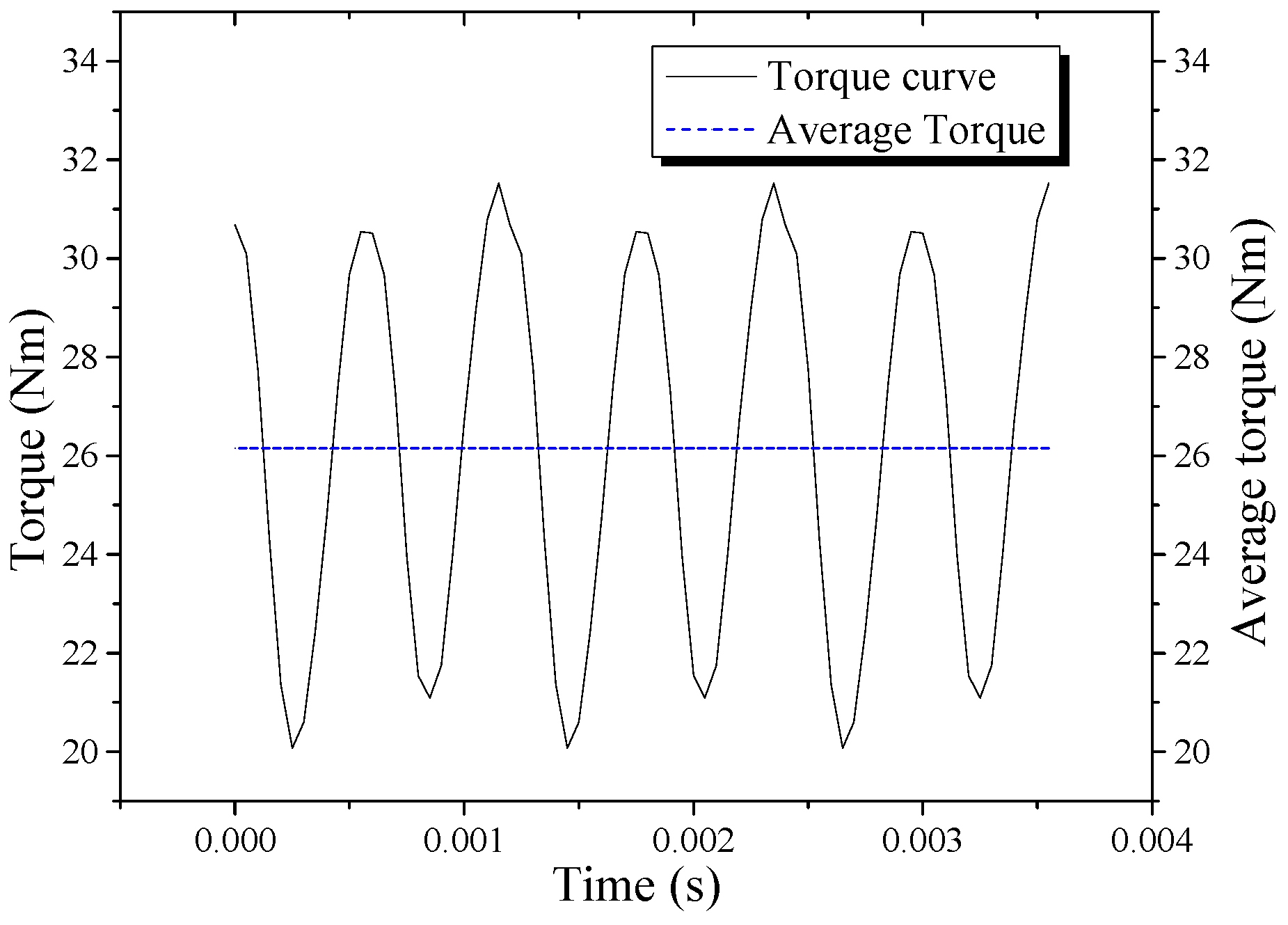
Figure 7, this adjustment can improve the power factor of the TFDRM, but it inevitably causes some sacrifice of the torque density. As for this method, we have to make a compromise between the power density and the torque density.
Figure 7.
Power factor and average torque versus ψ.
Figure 7.
Power factor and average torque versus ψ.
6. Optimization of the TFDRM
In the design of the TFDRM, high torque density is a major target to fulfill. Meanwhile, the power factor should be kept in a suitable range to avoid excessive control system capability. Considering these two aspects, the BEMF, average torque, and power factor versus main parameters are analyzed. The outline sizes are kept unchanged in the simulation.
In this section, FEM simulations are used to compare the influence of different parameters on machine performance. When the influence of one parameter is analyzed, the other parameters are kept unchanged. The optimization sequence of parameters is based on their degree of influence on the performance.
The pole-pair number and the length of outer/inner air gap are optimized first. The pole-pair number influences the frequency and further the torque density of TFDRM, which is different from traditional machines. Besides, it will influence the sizes of TFT and PMs in the following design. The two layers of air gaps even make the TFDRM different from general transverse-flux machines. The length of outer/inner air gap has a significant impact on the reluctance of main magnetic circuit.
The axial length of stator-core ending is next to those two parameters. Increasing the axial length of stator-core ending will enhance the axial length of TFT and offer more area for the main magnetic circuit. However, when the axial length of one phase is unchanged, increasing the axial length of stator-core ending will decrease the axial length of stator slot and lead to smaller cross-sectional area of stator slot.
After that, the width of TFT and the thickness of PMs are determined. Increasing the width of TFT can offer more area for main magnetic flux; but the possibility of leakage flux among the TFT also increases. Larger thickness of PMs is favorable for the magnetic flux, but it will cut down the size of iron poles. As a result, these two parameters should be chosen in a suitable range according to the simulation results. Finally the width of PMs, which has a simple impact and can be determined more freely than other parameters, is optimized.
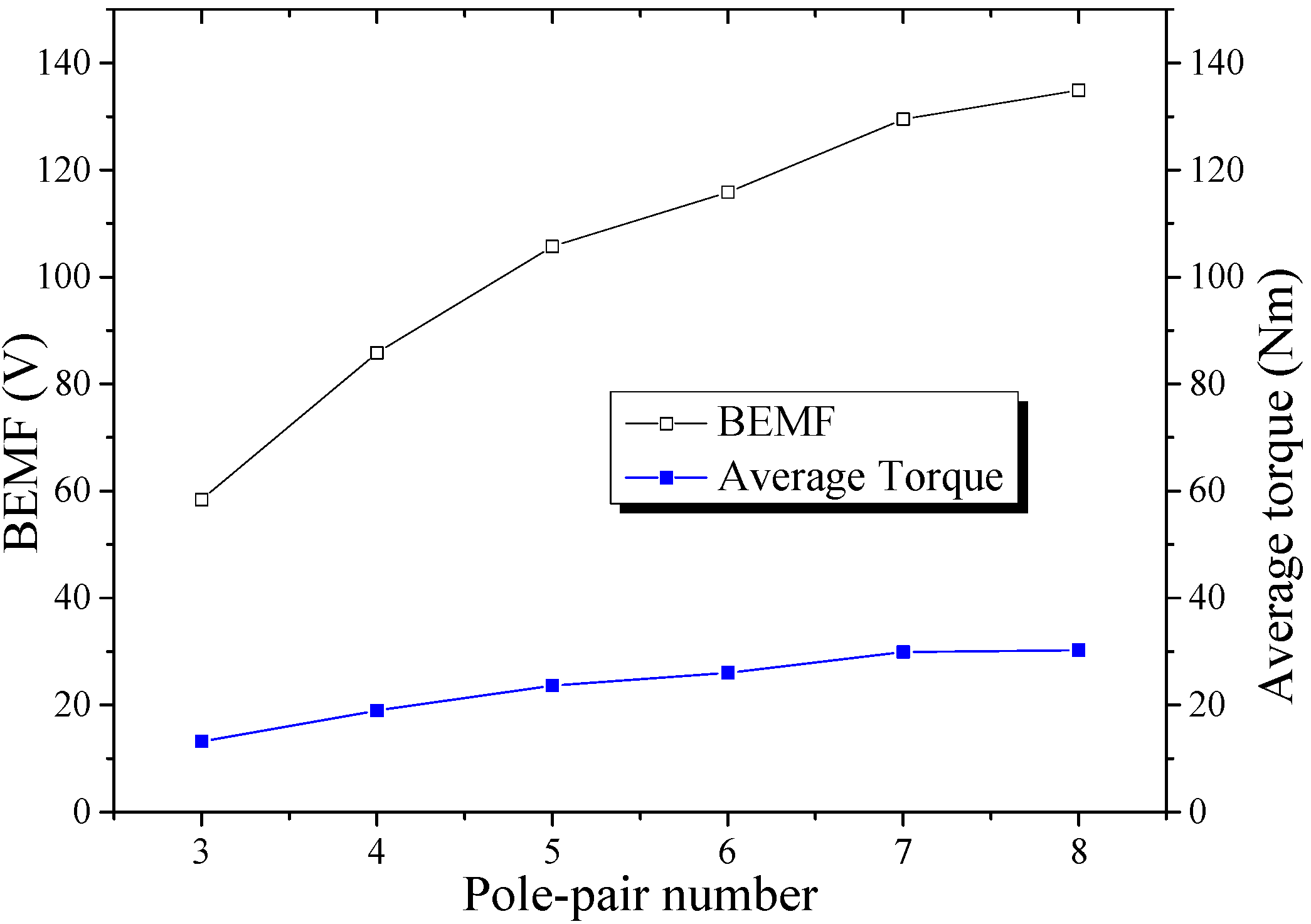
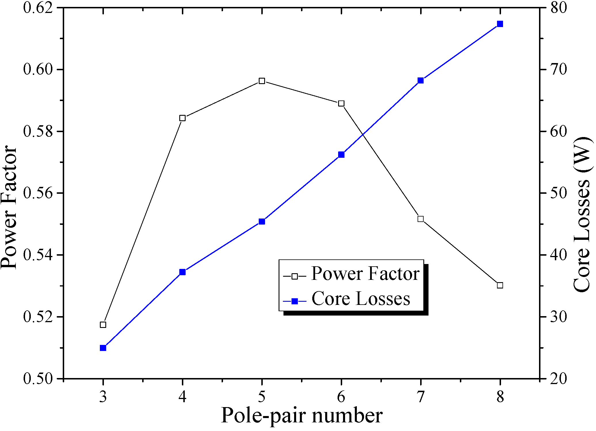
6.1. Pole-Pair Number
The pole-pair number is an important element in the optimization of the TFDRM. Generally speaking, the BEMF of the TFDRM increases with the pole-pair number, which is quite different from the traditional PMSMs. The simulation results are the same as the previous analysis, as shown in
Figure 11.
To enhance the output power, we intend to increase the pole-pair number. However, this will probably lead to an increase of the leakage flux and a poor power factor. As shown in
Figure 11 and
Figure 12, when the pole-pair number is larger than 6, the torque increase no longer becomes significant, but the power factor drops quickly. The power factor reaches the highest value when the pole-pair number is 5. To obtain high torque density and maintain a suitable power factor, the pole-pair number should be in the 4~6 range. The core losses increase with the increase of pole-pair number.
In addition, high pole-pair number also increases the difficulty and cost of manufacture. In the TFDRM, the TFT are some small units. For the adopted structure with stator outside and rotor inside, the rotor surface space is limited. The size of the TFT will become even smaller because of a larger pole-pair number, which will make the manufacture and assembly difficult, so considering all these aspects, the pole-pair number is chosen to be 6.
Figure 11.
Variation of BEMF and average torque versus pole-pair number.
Figure 11.
Variation of BEMF and average torque versus pole-pair number.
Figure 12.
Variation of power factor and core losses versus pole-pair number.
Figure 12.
Variation of power factor and core losses versus pole-pair number.
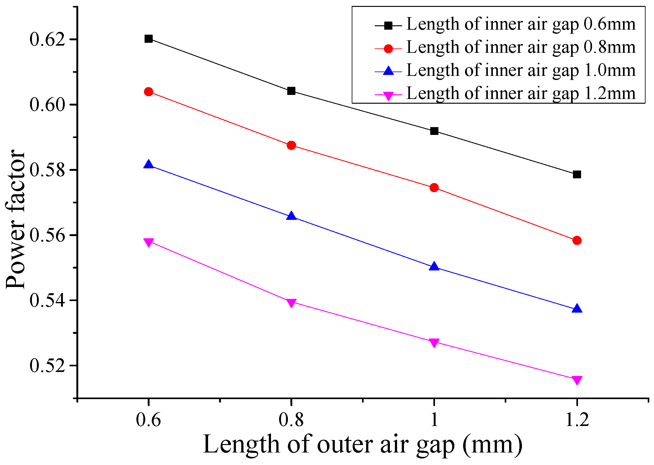
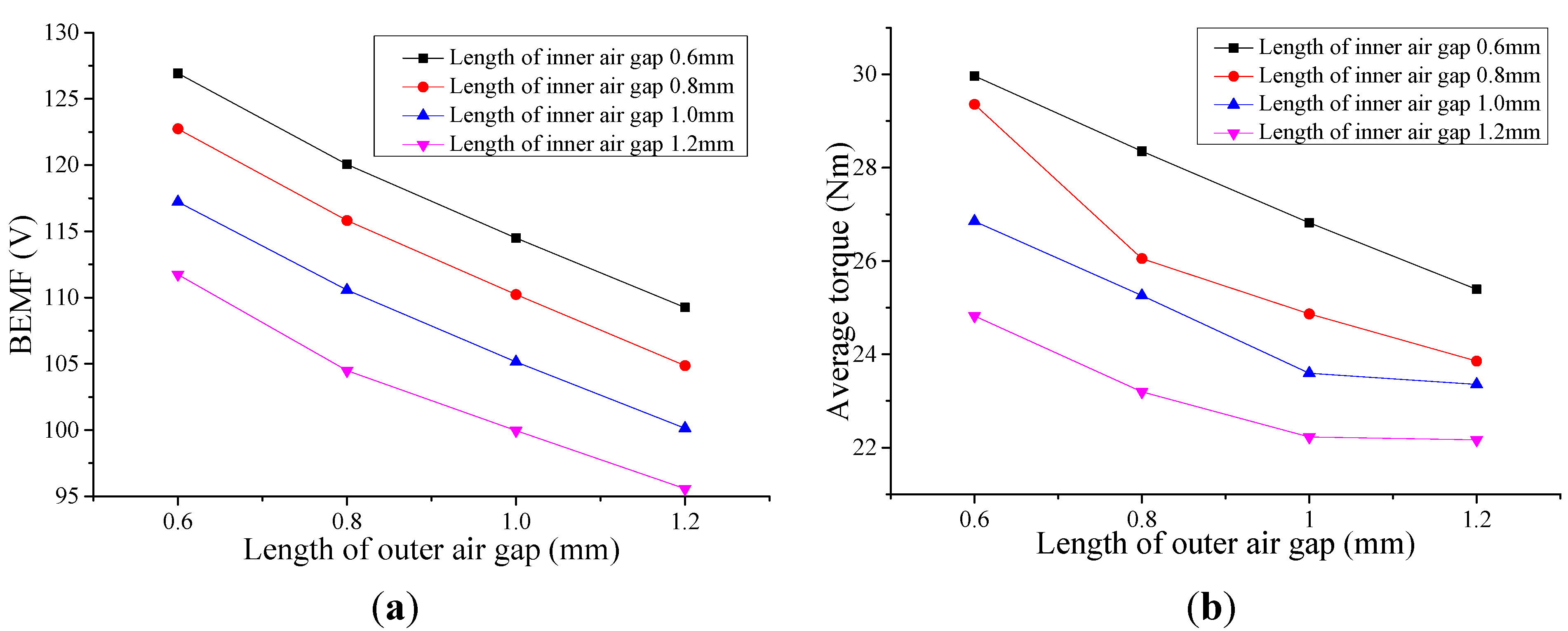
6.2. Length of Outer/Inner Air Gap
During the optimization, the length of outer/inner air gap is one of the most important factors. In the TFDRM, two layers of air gaps make the reluctance of main magnetic circuit much larger. The influence of the length of outer/inner air gap on the BEMF, average torque and power factor is shown in
Figure 13 and
Figure 14.
Figure 13.
Variation of BEMF and average torque versus length of outer/inner air gap: (a) BEMF; (b) Average torque.
Figure 13.
Variation of BEMF and average torque versus length of outer/inner air gap: (a) BEMF; (b) Average torque.
Figure 14.
Variation of power factor versus length of outer/inner air gap.
Figure 14.
Variation of power factor versus length of outer/inner air gap.
The simulation results show that decreasing the length of outer/inner air gap is favorable for improving the performance of the TFDRM. Different from most other methods, using a shorter outer/inner air gap length can also increase torque density when the power factor is improved. The cost of materials does not increase either due to the saving of PMs. However decreasing the outer/inner air gap length will increase the difficulty and cost of manufacture and assembly, so as a result, the length of the outer/inner air gap is chosen to be 0.8 mm.
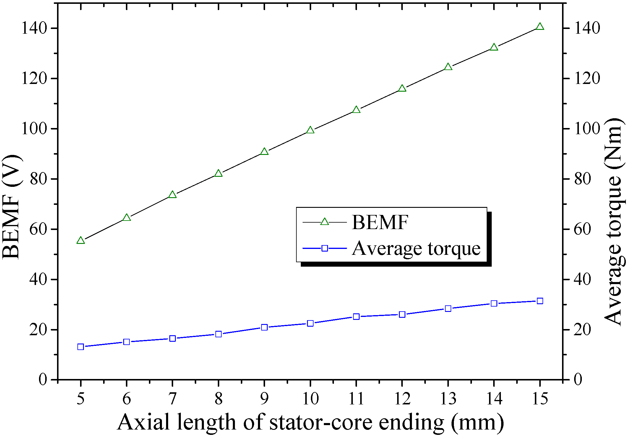
6.3. Axial Length of Stator-Core Ending
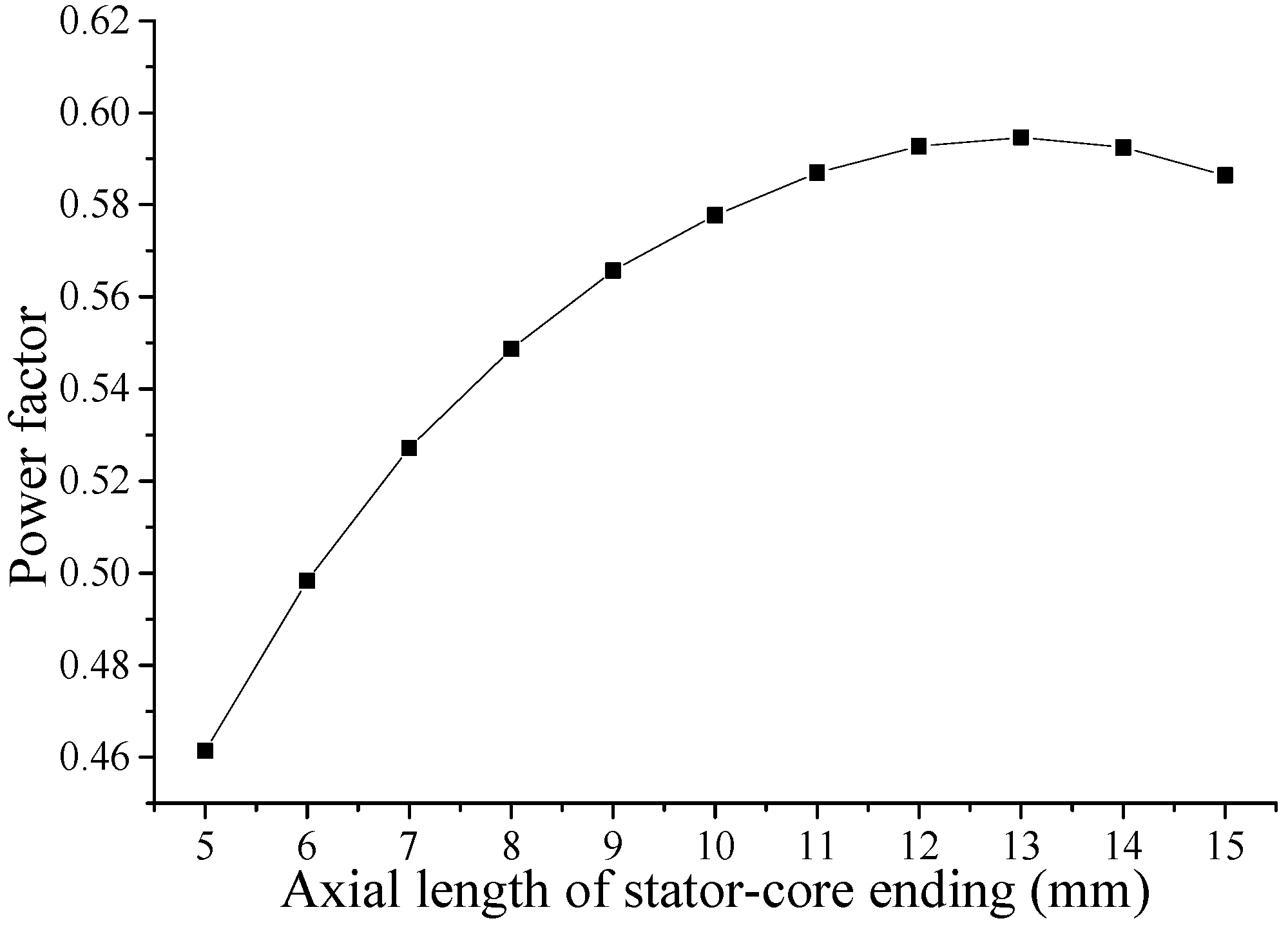
The stator core, which has a U-shaped cross section, is formed by two endings and a yoke. The increase of the axial length of the stator-core ending leads to a higher average torque.
Figure 15 shows the effect of axial length of the stator-core ending on the BEMF and average torque. Increasing the axial length of stator-core ending is favorable for the power factor, because more area can be offered for the magnetic flux Φ
m, but increasing the axial length of stator-core endings leads to a corresponding decrease of the axial length of the stator slot, which increases flux leakage among stator endings and influences the power factor. As a consequence, these two aspects have to be balanced by adjusting the axial length of the stator-core ending. As shown in
Figure 16, the 11~14 mm range is suitable for the axial length of stator-core ending. The length is chosen to be 13 mm.
Figure 15.
Variation of BEMF and average torque versus axial length of stator-core ending.
Figure 15.
Variation of BEMF and average torque versus axial length of stator-core ending.
Figure 16.
Variation of power factor versus axial length of stator-core ending.
Figure 16.
Variation of power factor versus axial length of stator-core ending.
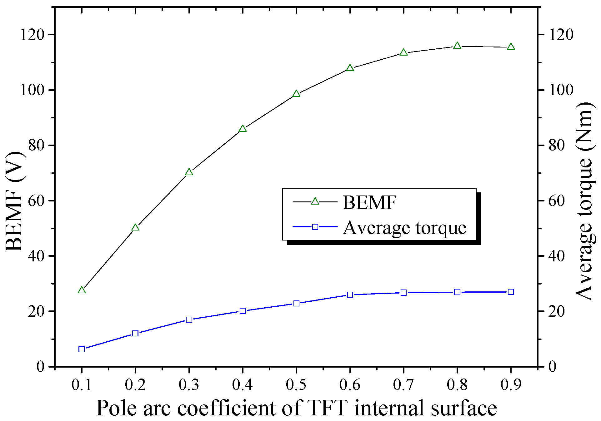
6.4. Width of TFT
The size of the TFT has a critical impact on the characteristics of the TFDRM. The geometrical optimizations of the TFT are mainly aimed at enhancing the average torque and reducing the leakage flux between two adjacent teeth. The pole arc coefficient of the TFT internal surface, which is in contact with the inner air gap, has an effect on the BEMF and average torque as shown in
Figure 17.
Figure 17 shows that the average torque reaches higher levels when the width of TFT is within the 0.7–0.9 range.
Figure 17.
Variation of BEMF and average torque versus pole arc coefficient of the TFT internal surface.
Figure 17.
Variation of BEMF and average torque versus pole arc coefficient of the TFT internal surface.
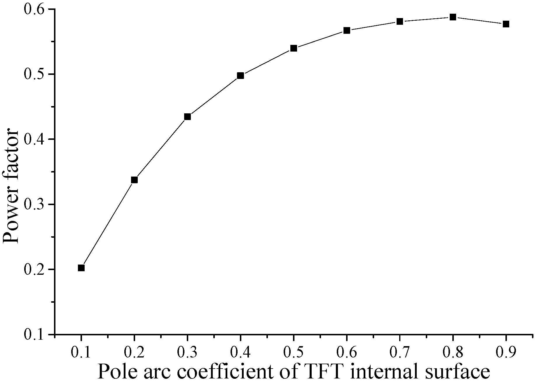
With the pole arc coefficient increasing, the torque increases, but this increases the probability of flux leakage among the TFT. As a result, the torque increases slightly when the pole arc coefficient is beyond a certain value. Meanwhile, the leakage leads to a poor power factor. According to
Figure 18, the width of TFT is chosen to be 0.8, which makes the power factor the highest.
Figure 18.
Variation of power factor versus pole arc coefficient of the TFT internal surface.
Figure 18.
Variation of power factor versus pole arc coefficient of the TFT internal surface.
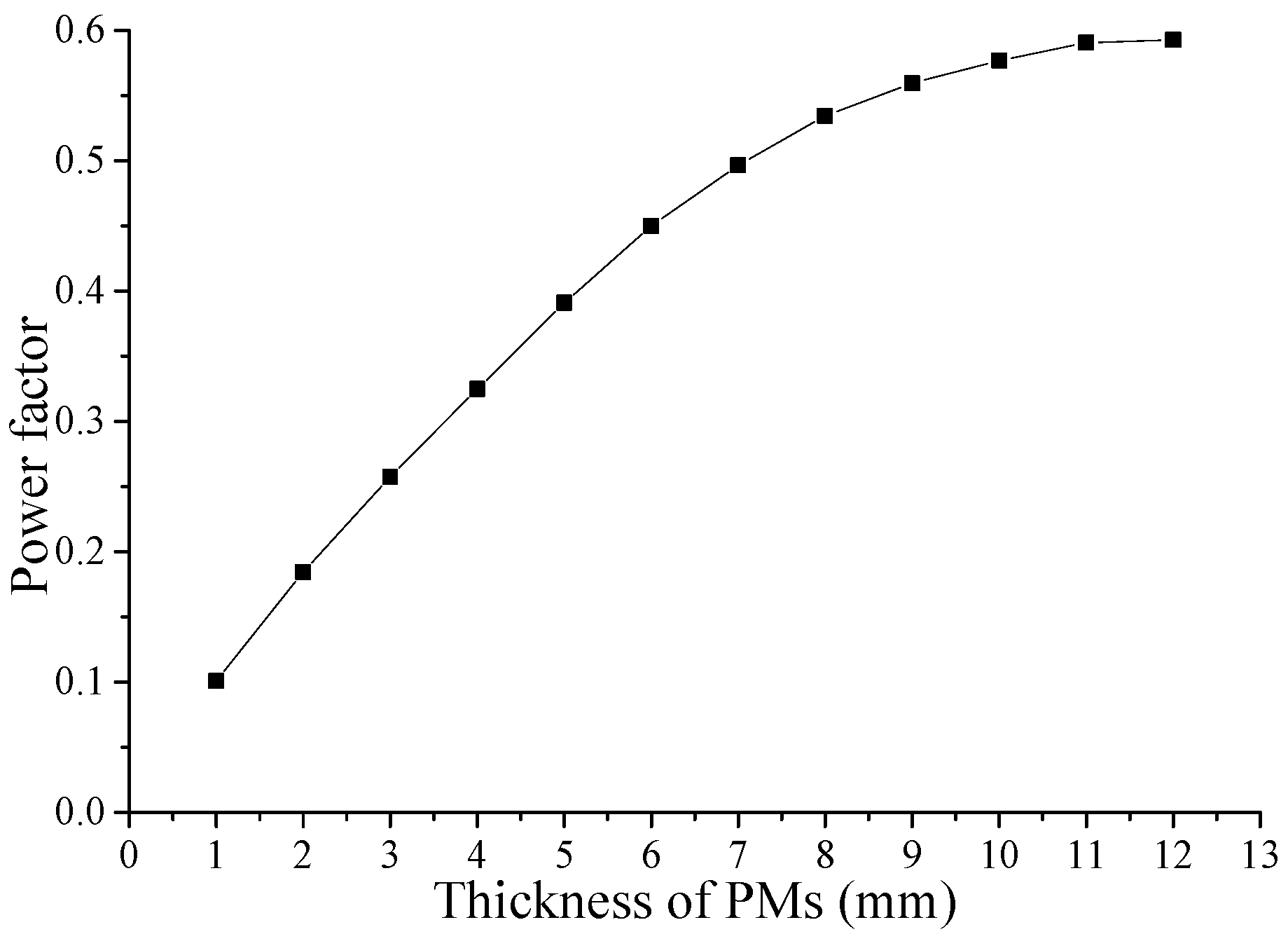
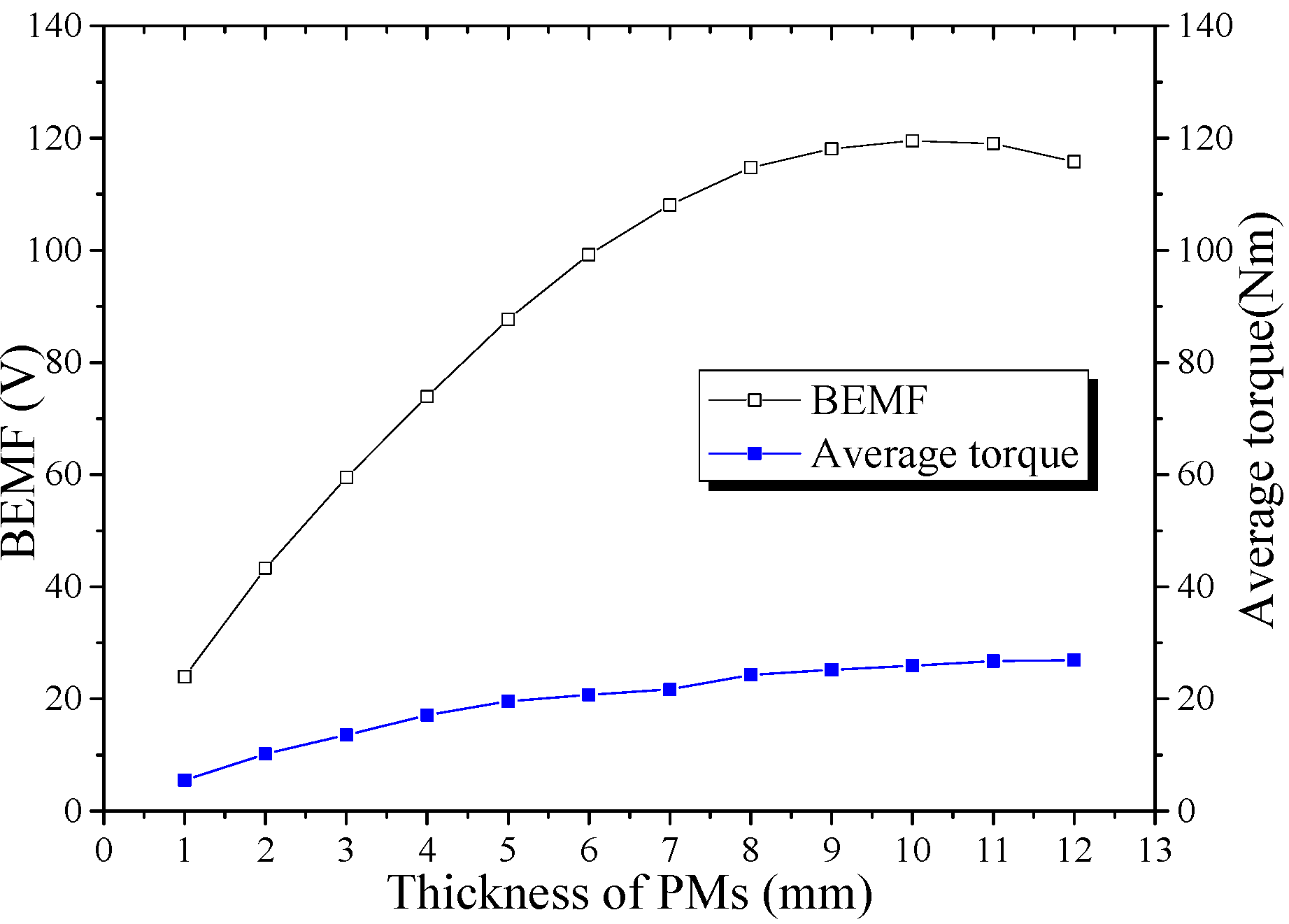
6.5. Thickness of PMs
In the TFDRM, the FC mode, which has distinguished characteristics, can also be adopted to concentrate and strengthen the flux density. Increasing the thickness of PMs can obtain higher BEMF, average torque and power factor, but the enhancement is slight when the thickness is bigger than 10 mm. The reason is that increasing the thickness will decrease the size of the iron pole. Consequently, when the thickness of PMs is too large, the magnetic flux concentration becomes worse; and the iron may face the problem of saturation. As shown in
Figure 19 and
Figure 20, the suitable value for the thickness of PMs is 10 mm.
Figure 19.
Variation of BEMF and average torque versus thickness of PMs.
Figure 19.
Variation of BEMF and average torque versus thickness of PMs.
Figure 20.
Variation of power factor versus thickness of PMs.
Figure 20.
Variation of power factor versus thickness of PMs.
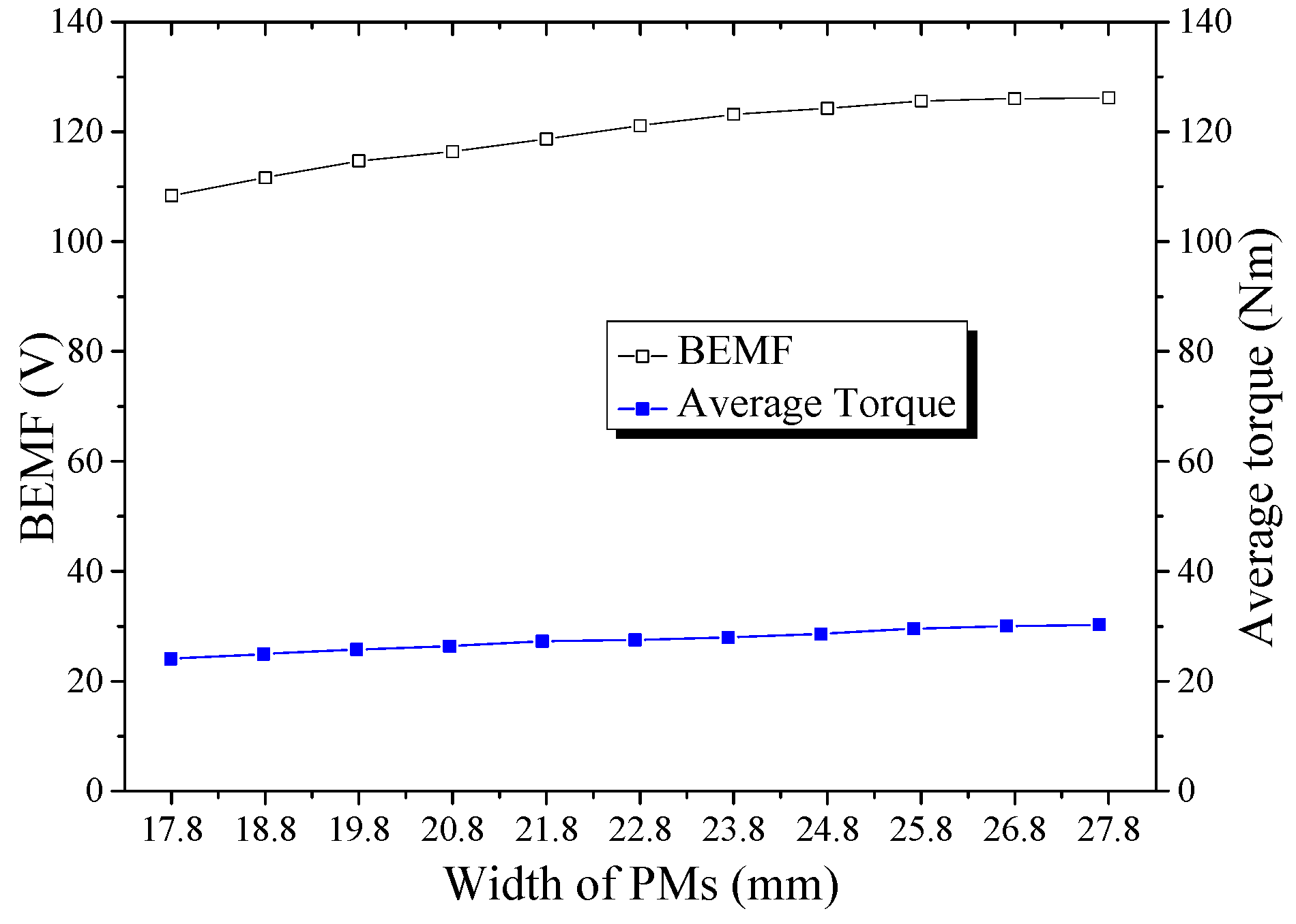
6.6. Width of PMs
Under the FC mode, to increase the width of PMs can increase the magnetic flux in the outer/inner air gap leading to a high torque.
Figure 21 shows the variation of the BEMF and torque with the width of PMs. Increasing the width of PMs can also improve the power factor, as shown in
Figure 22. The width of PMs has a simpler impact on the characteristics than other parameters. According to the simulation results, the width of PMs is chosen to be 27.8 mm.
Figure 21.
Variation of the BEMF and average torque versus width of PMs.
Figure 21.
Variation of the BEMF and average torque versus width of PMs.
Figure 22.
Variation of power factor versus width of PMs.
Figure 22.
Variation of power factor versus width of PMs.
Increasing the thickness and width of PMs can enhance torque density and power factor, but the cost of the TFDRM also increases, so the selection of the scheme is based on the balance of performance and cost.
6.7. Comparison between Initial and Optimized Design
The parameters and performances of the initial and optimized schemes are compared in
Table 1 and
Table 2, respectively. As can be seen from
Table 2, the BEMF, average torque, and torque density are all increased by using the optimized parameters. Especially, the power factor is enhanced significantly. Meanwhile, the THD of BEMF is also cut down.
Table 1.
Initial and Optimized Parameters of the TFDRM.
Table 1.
Initial and Optimized Parameters of the TFDRM.
| Parameters | Initial value | Optimized value |
|---|
| Pole-pair number | 6 | 6 |
| Stator outer diameter (mm) | 203 | 189 |
| Shaft diameter (mm) | 48 | 38 |
| Axial length of one phase (mm) | 44 | 44 |
| Outer air gap length (mm) | 1.0 | 0.8 |
| Inner air gap length (mm) | 0.8 | 0.8 |
| Axial length of stator-core ending (mm) | 9 | 13 |
| Axial length of stator slot (mm) | 26 | 18 |
| Pole arc coefficient of TFT internal surface | 0.7 | 0.8 |
| Axial length of TFT (mm) | 9 | 13 |
| Thickness of PMs (mm) | 7 | 10 |
| Width of PMs (mm) | 20.8 | 27.8 |
| Axial length of PMs (mm) | 44 | 44 |
Table 2.
Initial and Optimized Performances of the TFDRM.
Table 2.
Initial and Optimized Performances of the TFDRM.
| Performances | Initial value | Optimized value |
|---|
| Rated power (kW) | 10 | 10 |
| Number of phase | 3 | 3 |
| Rated speed (rpm) | 2800 | 2800 |
| Rated current (A) | 53.3 | 29.6 |
| Rated power factor | 0.28 | 0.61 |
| Winding turns in series per phase | 76 | 43 |
| Amplitude of fundamental no-load BEMF (V) | 70.2 | 126.2 |
| THD of BEMF (%) | 9.7 | 5.1 |
| Average torque (Nm) | 24.07 | 30.28 |
| Torque density (Nm/m3) | 5641.1 | 8192.2 |
6.8. Optimized Prototype of the TFDRM
A prototype of the TFDRM is designed and the parameters are shown in
Table 3. The prototype will be manufactured, and the results of simulation will be verified by experimental measurements.
Table 3.
Parameters of the TFDRM.
Table 3.
Parameters of the TFDRM.
| Parameters | Unit | Value |
|---|
| Rated power | kW | 10 |
| Number of phase | - | 3 |
| Rated speed | rpm | 2800 |
| Rated current | A | 29.6 |
| Number of poles | - | 12 |
| Rated efficiency | % | 89.5 |
| Rated power factor | - | 0.61 |
| Stator outer diameter | mm | 189 |
| Shaft diameter | mm | 38 |
| Axial length of TFDRM | mm | 132 |
| Outer air gap length | mm | 0.8 |
| Inner air gap length | mm | 0.8 |
| Winding turns in series per phase | - | 43 |
| Amplitude of fundamental no-load BEMF | V | 126.2 |
| THD of BEMF | % | 5.1 |


