1. Introduction
Conventional horizontal axis wind turbines (HAWTs) have a number of limitations for offshore operations, particularly in deep water (
i.e., over 50 m). For example; scalability restrictions, the necessity for high lift installations offshore requiring specialist vessels, high gravitational and aerodynamic moments on the support structure and a need to maintain rotary equipment at heights typically over 60–80 m. Consequently there has been a resurgence of interest in the development of vertical axis wind turbines (VAWTs) [
1,
2,
3,
4,
5,
6,
7,
8,
9,
10], which have several inherent attributes that offer some advantages for offshore operations, particularly their scalability and low over-turning moments with better accessibility to drivetrain components.
In 2009 the Energy Technologies Institute (ETI) commissioned “NOVA”, a £2.8M feasibility project to develop the design of a novel 10 MW offshore VAWT concept originally proposed by David Sharpe. Through detailed technological, economic and environmental assessments, a consortium that included industrial partners: Wind Power Ltd, OTM, QinetiQ, James Ingram Associates, CEFAS and DNV-GEC as well as Cranfield, Strathclyde and Sheffield Universities, developed a preliminary design over a period of 18 months.
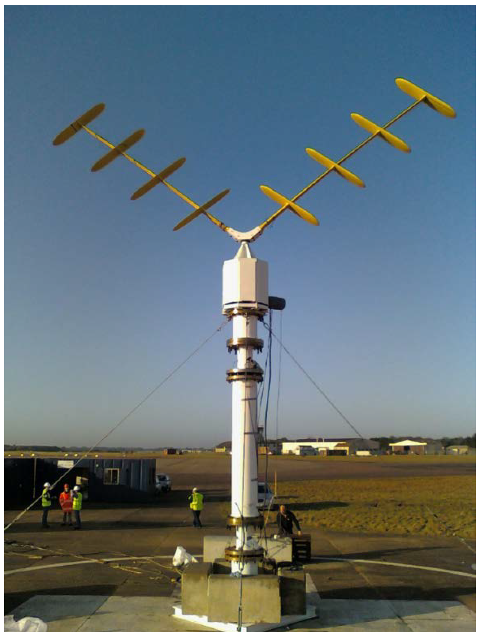
Figure 1 shows a photograph of a 5 kW prototype device developed by David Sharpe and Wind Power Ltd prior to the NOVA project, undergoing tests at Cranfield University. Its novel shape combines a V-rotor with several blades positioned along the span that are angled to minimise the aerodynamic over-turning moments (see Wind Power Ltd European Patent Application [
11]). The NOVA design was not primarily aimed at maximising aerodynamic efficiency but to deliver a low-stress design to minimise manufacturing and maintenance costs of the whole turbine assembly including the supporting structure and foundations.
Figure 1.
Prototype of original NOVA V-VAWT concept.
Figure 1.
Prototype of original NOVA V-VAWT concept.
In order to derive aerodynamic loads for the design of the external rotor shape, and for the structural design of the composite blades, steel hub and support structure, the structural dynamics, the mechanical design of the drivetrain, and the control system, a new aerodynamic performance model was developed by Cranfield University and QinetiQ. This was necessary since no commercial tools were available and existing research tools had been developed for VAWT rotors with quite different shapes
i.e., curved troposkien (
i.e., Φ-shaped) blades or straight H-shaped rotor blades. This paper describes the development and evaluation of this aerodynamic performance model which was based on Paraschivoiu’s Double-Multiple Streamtube (DMST) model [
12].
For the NOVA concept there are aerodynamic losses associated with the multiple aerodynamic surfaces that can be significantly greater than for conventional VAWTs. For example, the parasitic drag due to junction regions and induced drag and lift losses from multiple finite aspect ratio blades must be included. It was also necessary to modify the standard multiple-streamtube approach in order to evaluate the momentum losses created by more complex rotor geometries.
Since the performance of VAWT rotors is significantly influenced by the dynamic stall (DS) phenomena, a complex and unsteady lag effect that blades can experience during rapid pitch oscillations, the Gormont semi-empirical DS model [
13] has been included, with corrections proposed by Masse [
14] and Berg [
15]. However, previous researchers have identified a need to tune the DS model parameters for different VAWT configurations. This research proposes a further modification to the Gormont DS model that is more accurate for H-rotor configurations, and a means of pre-determining a suitable value of Masse coefficient based on the blade chord length.
The turbine model was developed with the flexibility to model Φ-, H-, and V-shaped VAWT configurations and the paper presents comparisons of predicted power with published measured data for five “conventional” medium to large VAWTs with rated powers in the range 100–500 kW. Whilst these cases give confidence in the accuracy of the method compared with other momentum tools, results for the 5kW NOVA prototype device are also described.
Section 2 of this paper describes the main developments of the aerodynamic model and predicted results are presented in
Section 3. A discussion of the relative accuracy of the method is given in
Section 4 and concluding remarks in
Section 5.
2. Aerodynamic Performance Model
The aerodynamic performance of a VAWT rotor is a critical factor in assessing the overall economic justification of a wind turbine project. A reliable validated prediction methodology is therefore essential for assessing potential NOVA rotor designs. However, predicting the aerodynamic loads of VAWT rotors is non-trivial with blades operating with both attached and separated flow regimes and blade elements passing through multiple wakes, giving a range of complex flow physics. Computational fluid dynamics methods are capable of predicting these flows but require a high level of computational resources. In contrast, solutions of the momentum flow equations,
i.e., Streamtube models, use minimal computational resources and can give good accuracy for most operating conditions when combined with semi-empirical corrections for three-dimensional and unsteady flow effects. Momentum theory assumes that the streamwise aerodynamic force on the rotor blades is equal to the rate of change of momentum of air within a streamtube. Computations are performed for a series of streamtubes which pass through the rotor giving rise to a non-uniform velocity distribution. Such methods were originally developed in the 1970’s by Templin [
16] and Strickland [
17] to support the development and testing of several Φ-rotor VAWT turbines by the National Research Council (NRC) in Canada and Sandia National Laboratories (SNL) in the USA, respectively. More recently, Paraschivoiu [
12] made some significant improvements by performing separate calculations of induced velocity over upwind and downwind half-cycles of the rotor. The model developed for this project is based on Paraschivoiu’s DMST model which evaluates momentum losses for several vertical and lateral streamtubes passing through the rotor. In so doing a 3-D induced velocity field can be derived. In the present model momentum losses created by several aerodynamic surfaces are averaged over lateral streamtubes over each half-cycle (
i.e., upstream and downstream cycles). This modification was necessary for complex rotor shapes. The model also includes a modified DS model and allowances for wind shear, blade-tip, junction and tower losses.
2.1. Blade Element Loads
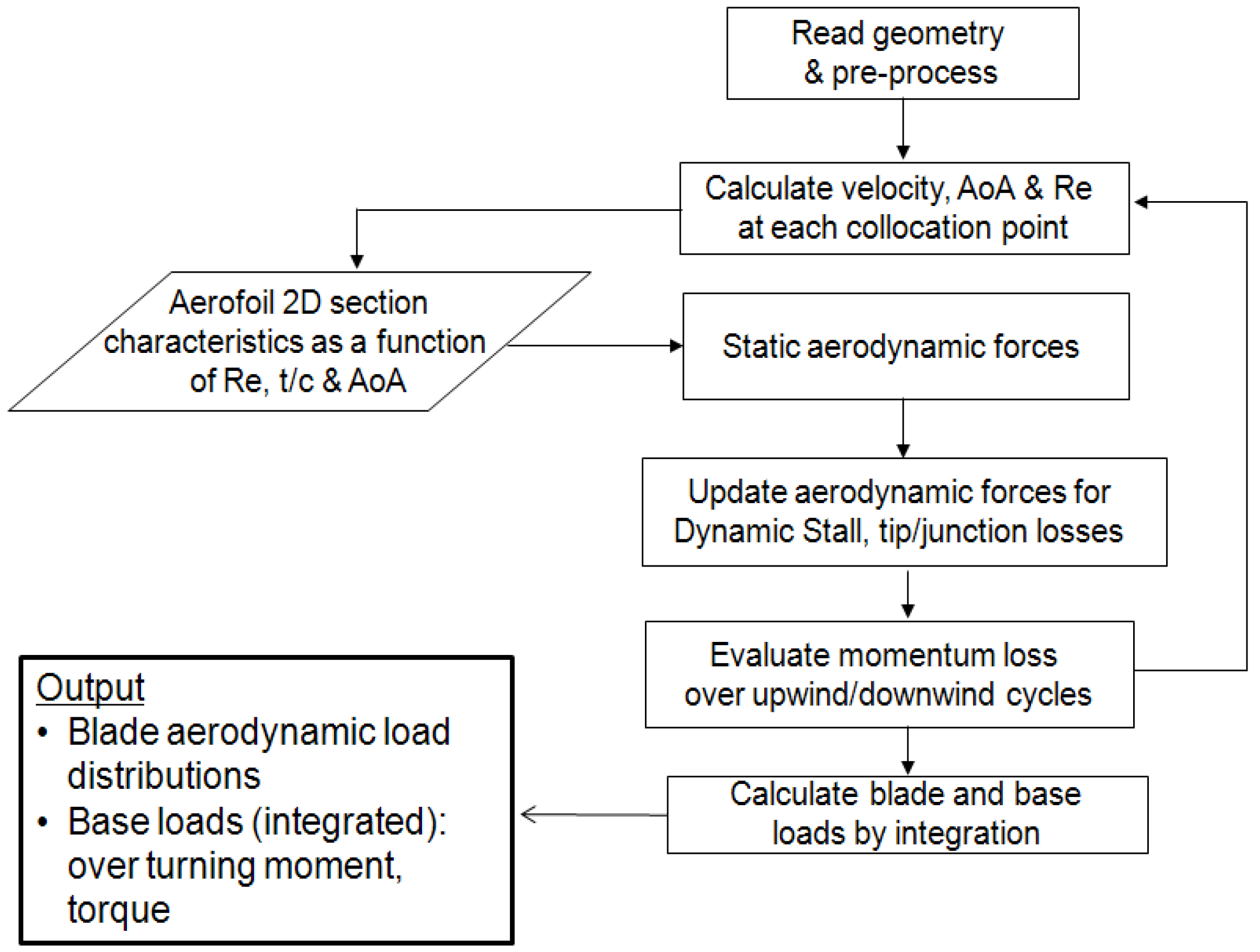
A schematic of the turbine model operation is shown in
Figure 2. The rotor geometry is pre-processed by distributing nodes (
i.e., blade elements) on all aerodynamic surfaces including any support struts. For a defined freestream wind profile,
, and rotational speed (
), the local induced wind velocity (
U), relative velocity (
W), geometric angle of attack (
) and chord Reynolds number (
Rc) at each corresponding node is calculated for each blade azimuth position (
θ) using Equations (1–3) (as described in [
18]):
where
c and
r are the local blade chord and radius respectively;
is the blade inclination angle;
is the local blade twist angle; and
is the ambient air density.
Figure 2.
Schematic of the turbine model operation.
Figure 2.
Schematic of the turbine model operation.
As with other blade element momentum (BEM) models, this model uses a database of static aerofoil lift (
) and profile drag (
) coefficients that is generally obtained from wind tunnel experiments. The database is interpolated to obtain the static 2-D aerodynamic forces at the corresponding Reynolds number and angle of attack that are subsequently modified to include 3-D and DS effects as described in
Section 2.3 and
Section 2.4, respectively.
The turbine model also allows the inclusion of static lift and drag data for a family of aerofoils so that the effect of shape variables, such as maximum thickness, can be represented in the design process. Measured characteristics from wind tunnel tests of the NACA 00** series of aerofoils, ranging in thickness from 12% chord to 25% chord [
19], were used for model evaluation and in the design of the NOVA rotor. Post-stall characteristics were represented by an analytical expression for a flat plate lift and profile drag, given by:
Coefficients used in these analytical expressions were chosen to give good agreement with measured static data at moderate angles of attack. For struts that have an elliptical profile, an empirical drag coefficient is assumed given by Hoerner [
20]:
and the turbulent skin friction coefficient,
Cf turb, is approximated by assuming the turbulent boundary-layer growth over an equivalent flat plate. Equation (1) is used to approximate the strut lift coefficient.
Momentum loss contributions from nodes at each height interval are evaluated to derive induced velocities for the upwind and downwind half-cycles (approximately 200 height intervals are considered). For the upwind half-cycle, an induction factor
is determined from Equations (6–8), similar to that described in [
18]:
where
N is the number of blades and
denotes the upwind induction factor calculated for the previous iteration. Contributions are summed for all of the nodes
i.e.,
n1 to
nj, that pass through each lateral streamtube at the current height interval. The function
is evaluated from the nodal normal force coefficient (
) and tangential force coefficient (
) at blade azimuth positions in the range
θ = −90° to +90° in increments
∆θ = 5° (
i.e., for 37 lateral streamtubes). Consequently, the upwind induced velocity can be updated using Equation (9) (
= 1 is assumed for the initial iteration) and an iterative procedure used to update the induced velocity until convergence is achieved:
Once the upwind induced velocity is determined, the downwind induction factor
is derived from Equations (10), (7) and (8) and used to update the downwind induced velocity using Equation (11):
Thus an induced velocity field is derived for each operating condition comprising a vertical variation of velocity for both the upwind and downwind half-cycles. Whilst the model of Masson
et al. [
18] also develops a lateral variation of induced velocity at each height interval, the present model averages momentum losses laterally to include the losses from multiple blade elements when modeling more complex rotor shapes. However, results presented in
Section 3 indicate that this simplification does not adversely influence the performance of the model relative to results presented by Paraschivoiu and Masson
et al. [
12,
18].
2.2. Wind Profiles
The turbine model has been coupled with the TURBSIM model [
21], allowing stochastic onset wind profiles to be considered. However, all results presented in this paper have assumed a relatively simple power-law variation of freestream wind speed (
U∞) with height (
h), relative to a reference wind velocity (
Uo) measured at a height (
ho) given by:
Using anemometry heights (ho) specified for each experimental wind turbine, the local freestream wind speed is evaluated assuming a wind shear exponent, α = 0.16, being representative of open level terrain with no trees, typical of these experimental facilities.
2.3. Three-Dimensional Aspects
One of the major limitations of the original BEM theory is that there are no finite aspect ratio (i.e., 3D) considerations. An unbounded blade tip will shed vortices due to the pressure differential producing a local reduction in lift and an additional induced drag component. Although Φ-rotor configurations are not significantly influenced by tip losses, they are significant for H- and V-rotor configurations and tip losses should be included in a similar manner to that of HAWT BEM models.
Thus, a boundary condition is specified for the tip (
i.e., spanwise extent) of each surface to identify bounded or unbounded tips and for the latter case the spanwise lift distribution is modified to include tip losses. A Prandtl lift loss is imposed by applying a factor to the 2D lift coefficient based on the nodal non-dimensional spanwise position (
), local angle of attack and the number of blades, similar to that used for the AeroDyn HAWT BEM model [
22]:
Furthermore an induced drag contribution is added to the profile drag at each node given by:
where
AR is the blade or strut aspect ratio; and
k is a loading efficiency factor generally assumed,
k = 0.9.
A further correction for 3D flows not generally included in BEM models is to account for junction losses. A horseshoe vortex is established at the intersection of a streamlined section with an end plate that results in a momentum loss. A suitable study to determine the drag associated with these secondary vortices is described by Roach and Turner [
23]. A principal observation was that for streamlined struts, the associated drag coefficient increase can be given by:
where
h is the strut length;
t/c is the strut thickness/chord ratio; and
δ* is the end-wall boundary layer thickness which can be approximated by assuming the turbulent boundary-layer growth over an equivalent flat plate. The tip boundary condition is used to identify junction regions where a junction drag increment,
CD(J), is added to the profile and induced drag, though this increment is comparatively small.
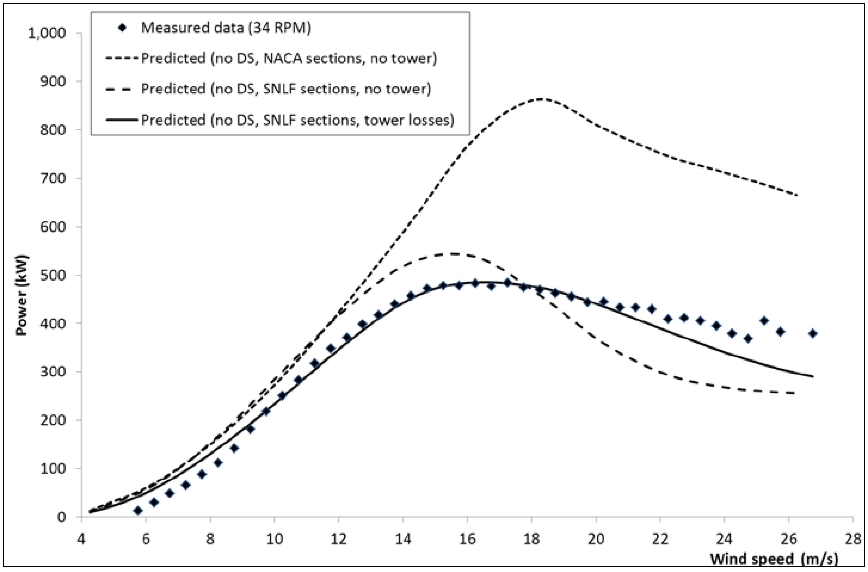
Following the 1974 oil crises, Sandia National Laboratories (SNL) together with the U.S. Department of Energy, jointly developed and field-tested several Darrieus wind turbines.
Figure 3 compares the variation of measured and predicted power with wind speed for the SNL 34 m diameter test machine that began operating in May 1988. Turbine geometry and measured power data is published by Ashwill [
24]. This 2-bladed turbine has a troposkien Φ-shaped rotor with 18% thick sections over the equatorial region of the blade and 21% thick sections near the blade roots. Modelling initially assumed aerodynamic data for the NACA 0018 profile for equatorial stations, giving a significant over-prediction of power shown in
Figure 3, particularly at higher wind speeds. However, equatorial sections featured a bespoke natural laminar flow (NLF) aerofoil section, SNL 0018/50. With wind tunnel data for this aerofoil provided by SNL, further calculations were performed and
Figure 3 shows a much improved calculation of power relative to the measured data. The comparison also indicates that the turbulent NACA section profile is more efficient at higher wind speeds than the NLF section. The NLF section is expected to be more efficient at low wind speeds where laminar flow can be maintained more reliably due to the smaller range of operating angles of attack giving a lower profile drag relative to the turbulent section, though any improvement shown in
Figure 3 is marginal.
Figure 3.
Sandia 34m Φ-rotor power vs. wind speed at 34 rpm.
Figure 3.
Sandia 34m Φ-rotor power vs. wind speed at 34 rpm.
Figure 3 shows predicted power is still generally higher than was measured using the correct section data. Due to the relatively large 3m diameter tower, a further correction was included to account for tower wake losses. This is only applied for the downwind rotor cycle by modifying the induced velocity by a factor:
where
DT is the tower diameter and
DR is the maximum rotor diameter at the given height. Using this simple tower wake correction,
Figure 3 shows that the predicted power is in very good agreement with measured data over most wind speeds at 34 rpm. All calculations presented in this paper include the 3D considerations for tip lift losses, induced and junction drag and tower losses as appropriate.
2.4. Dynamic Flow Considerations
The DS phenomena results from unsteady lag effects as an aerofoil experiences a rapidly changing pitch angle. Initially, as the pitch angle increases beyond the static stall onset angle the dynamic lift increases beyond the maximum lift for quasi-steady conditions due to the unsteady boundary layer response and the effect of induced camber. Consequently, the effective pitch angle is lower than the instantaneous angle resulting in a delay in the onset of separation. More significantly, when separation occurs a strong vortex may be shed from the leading edge of the aerofoil which travels downstream thereby augmenting the lift of the section whilst the vortex remains above the aerofoil. When the vortex is shed from the trailing edge the lift decreases abruptly due to a state of full flow separation, often resulting in a lower lift than that corresponding to quasi-steady conditions. Flow reattachment can also occur at pitch angles lower than that corresponding to static stall onset due to the lag effects associated with the unsteady boundary layer response. The qualitative features of the DS process often remain similar for varying Reynolds numbers and forcing conditions, though the quantitative behavior of the aerodynamic forces and moments show variations for different airfoil shapes, thereby proving to be a challenge for the rotor analyst.
The degree of lift augmentation, the timing of vortex shedding, and the onset of vortex formation is dependent on factors such as the aerofoil shape, mean angle, amplitude and rate of oscillation, and compressibility effects. In general, three main categories of DS models that have been published in literature exist [
25]:
The actual kinematics of the DS process such as the time delay effects on leading edge pressure response, vortex formation, and vortex shedding are modelled (e.g., Beddoes-Leishman model [
26]);
The mechanics of the DS process are neglected, and the characteristics of the lift curve are modelled (e.g., ONERA model [
27]);
A reference pitch angle is introduced that mimics the effective pitch angle under dynamic conditions (e.g., Gormont model [
13]).
The Gormont DS model, initially developed for helicopter rotor applications, was selected since it lends itself readily for implementation in VAWT BEM models and has been shown to provide good accuracy [
12,
18]. The Gormont model empirically mimics the hysteresis response of an aerofoil by defining a reference angle of attack to which the static two-dimensional coefficient data can be extrapolated. This reference angle of attack,
, is given by:
where
is a function of the aerofoil pitch rate as given by Gormont [
13]. The dynamic lift and drag coefficients are calculated using Equations (18) and (19):
where
and
are the angles of attack corresponding to zero-lift and static stall respectively.
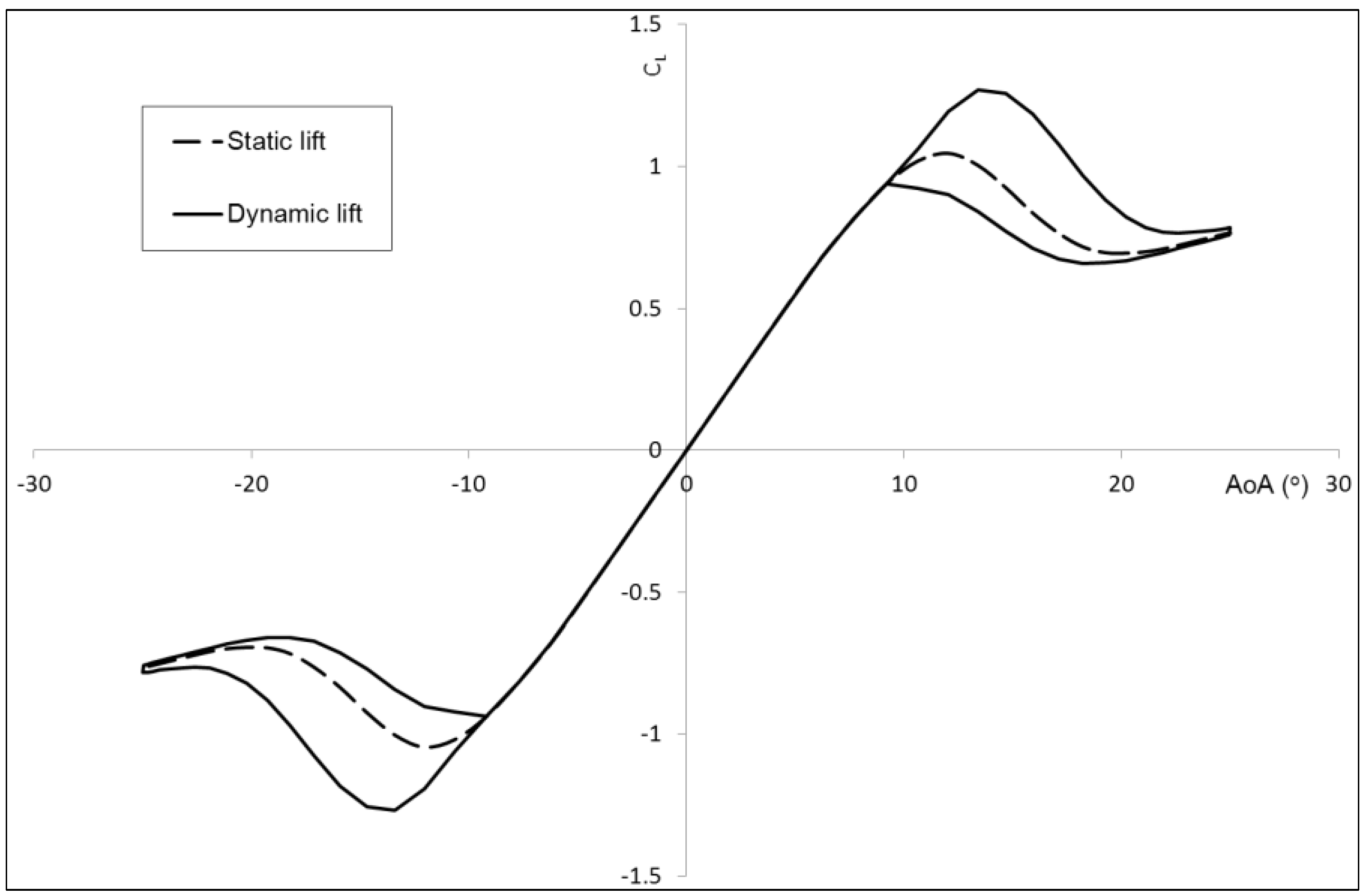
A typical hysteresis response of dynamic lift predicted using this model is presented in
Figure 4 compared with static lift coefficients. The static stall angle is defined as the condition corresponding to the onset of trailing edge separation of the static aerofoil giving rise to a change in lift curve slope, and occurs at approximately 7° in
Figure 4. Beyond the static stall angle, dynamic lift continues to increase almost linearly until a breakdown occurs. This breakdown is associated with the point when the leading edge vortex has travelled past the aerofoil trailing edge corresponding to large flow separation and lift loss.
Figure 4.
Typical hysteresis response of dynamic lift.
Figure 4.
Typical hysteresis response of dynamic lift.
Since the Gormont model has been developed for helicopter applications, it has been speculated that it over-predicts the effects of DS on VAWT performance since the maximum angle of attack reached is generally higher than is typical for helicopter blades. Masse [
14] proposed to modify the dynamic coefficients based on a linear interpolation between the static coefficients and the dynamic coefficients predicted by the Gormont model, defining an empirical damping coefficient
AM = 1.8. These modified lift and drag coefficients are calculated using Equations (20) and (21) respectively:
Similarly, Berg [
15] proposed a modified Masse coefficient,
AM = 6, which gave good agreement between the predicted and experimental performance of the SNL 17m diameter Darrieus turbine. A further adaptation proposed by Brochier
et al. [
28] neglects the effects of dynamic stall within a range of azimuth angles due to increased turbulence levels that can delay the occurrence of dynamic stall.
The effects of these different adaptations of Gormont’s model were studied by Masson
et al. [
18] which suggested that the most accurate DS implementation, based on performance comparisons of 3 Φ-shaped turbines, was to use the Masse damping coefficient. Furthermore, it suggested that the optimal value of Masse coefficient (
AM) is a function of section thickness, with
AM = 6 for blades with 15% thick sections and
AM = ∞ for 18% thick sections.
This study proposes that the optimal value of
AM is also a function of blade chord and suggests alternative values based on calculations for three Φ-shaped turbines (also included in the study by Masson
et al. [
18]) and two H-shaped turbines with rated powers in the range 100–500 kW. In addition, this study has identified a further modification to the Gormont model that is more appropriate for H-shaped rotors in particular, and neglects dynamic lift and drag for negative pitch rates by adopting:
3. Performance Model Results
Table 1 summarises the VAWT rotors considered for this study with geometry data and optimal values of Masse coefficient that are suggested for each turbine and rotational speed considered.
Table 1.
Dynamic stall parameters recommended for different turbines.
Table 1.
Dynamic stall parameters recommended for different turbines.
| Turbine | RPM | Rotor diameter (m) | Section t/c | Mean chord (m) | Solidity | Suggested AM | DS |
|---|
| VAWT-260 | 33 | 19.5 | 0.18 | 1.02 | 0.105 | 6 | On |
| VAWT-850 | 13.6 | 35 | 0.18 | 1.84 | 0.105 | 11 | On |
| NRC 24m | 29.4 | 24 | 0.18 | 0.61 | 0.1 | 3.6 | On |
| NRC 24m | 36.6 | 24 | 0.18 | 0.61 | 0.1 | 3.6 | On |
| SNL 17m | 42.2 | 16.6 | 0.15 | 0.61 | 0.14 | 6 | On |
| SNL 17m | 50.6 | 16.6 | 0.15 | 0.61 | 0.14 | 6 | On |
| SNL 34m | 28 | 34 | 0.18/0.21 | 1.03 | 0.13 | - | Off |
| SNL 34m | 34 | 34 | 0.18/0.21 | 1.03 | 0.13 | - | Off |
| SNL 34m | 38 | 34 | 0.18/0.21 | 1.03 | 0.13 | - | Off |
For all turbines predicted power curves are compared with measured field data for three conditions;
The predicted power presented in
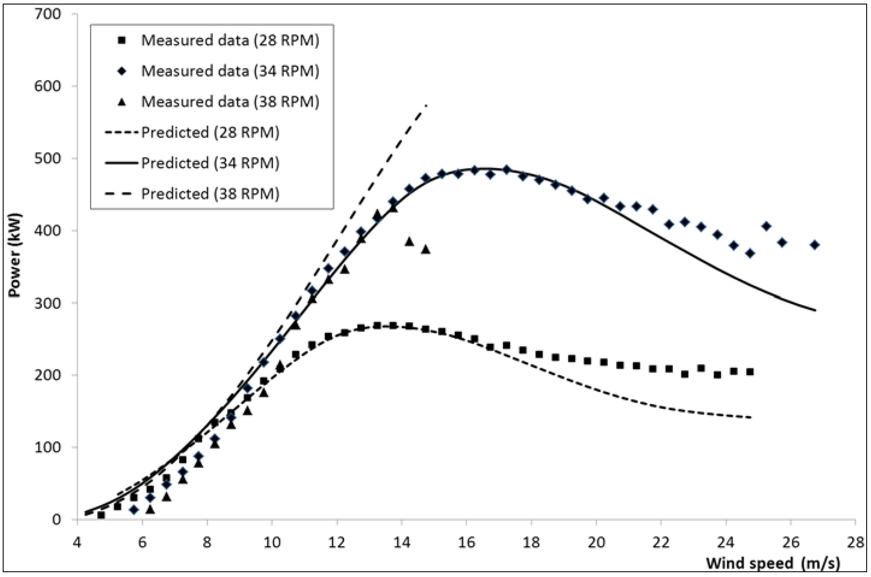
Figure 3 for the SNL 34 m diameter turbine neglected to include any unsteady effects due to the DS phenomena since the present study found that DS has little influence on power for this turbine. Predicted and measured power for this turbine is presented in
Figure 5 for the additional rotational speeds of 28 and 38 rpm, also with the DS option switched off. For the two lower rotational speeds of 28 and 34 rpm the predicted power is mostly in good agreement up to wind speeds of ~16 m/s and ~20 m/s respectively. However, at low wind speeds the power is over-predicted for all rotational speeds. This result was also observed by Berg [
15] at SNL using their DMST model and was attributed to non-faired step changes in chord and aerofoil section and to the inherent inaccuracies at low speeds of DMST codes. At the higher rotational speed of 38 rpm, the reduction in power due to blade stall for wind speeds above 14 m/s is not captured adequately by the model.
Figure 5.
Sandia 34m Φ-rotor power vs. wind speed.
Figure 5.
Sandia 34m Φ-rotor power vs. wind speed.
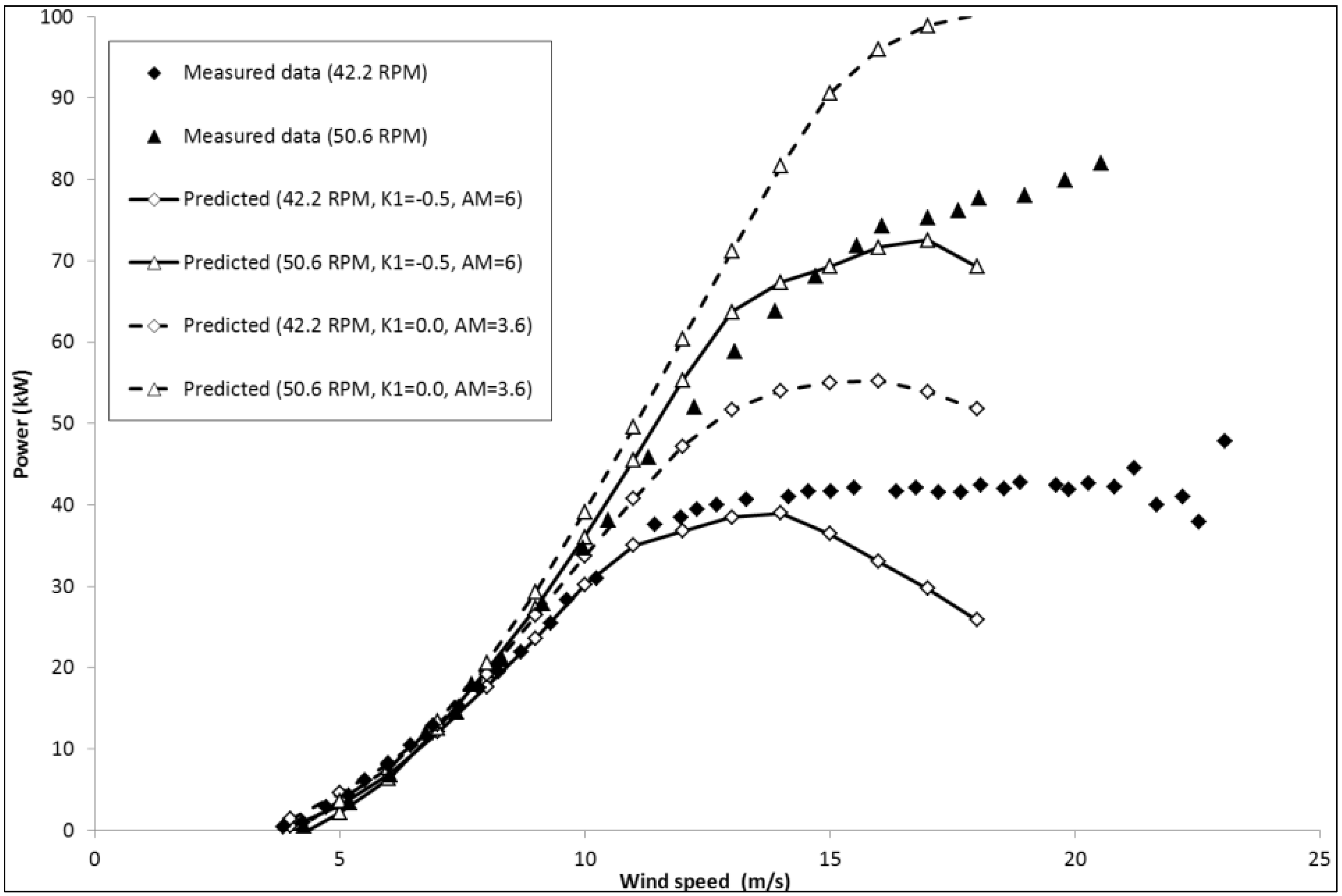
The SNL also developed the troposkien Φ-shaped 17 m diameter research machine which proved to be very successful and was later commercialised by FloWind Corp. which built and operated over 500 similar turbines. Turbine geometry is based on a later configuration using the NACA 0015 blade profile and horizontal support struts. Using the SNL momentum method, Berg [
15] suggested that a Masse coefficient,
AM = 6, gave good agreement between the predicted and experimental data for this turbine. This was also observed using the present model and power results are compared for this turbine in
Figure 6 using the original Gormont implementation for negative pitch rates (
i.e.,
K1 = −0.5 in Equation (17) and
AM = 6) and using the modified implementation (
i.e.,
K1 = 0.0 in Equation (22) and
AM = 3.6). The figure shows good agreement between measured and predicted power using the original Gormont implementation except for wind speeds over approximately 14 and 18 m/s for rotational speeds of 42.2 and 50.6 rpm respectively, where the model begins to under-predict the power when the blades encounter deep stall. For this turbine the proposed DS modification over-predicts the power.
Figure 6.
Sandia 17m Φ-rotor power vs. wind speed at 42.2 and 50.6 rpm.
Figure 6.
Sandia 17m Φ-rotor power vs. wind speed at 42.2 and 50.6 rpm.
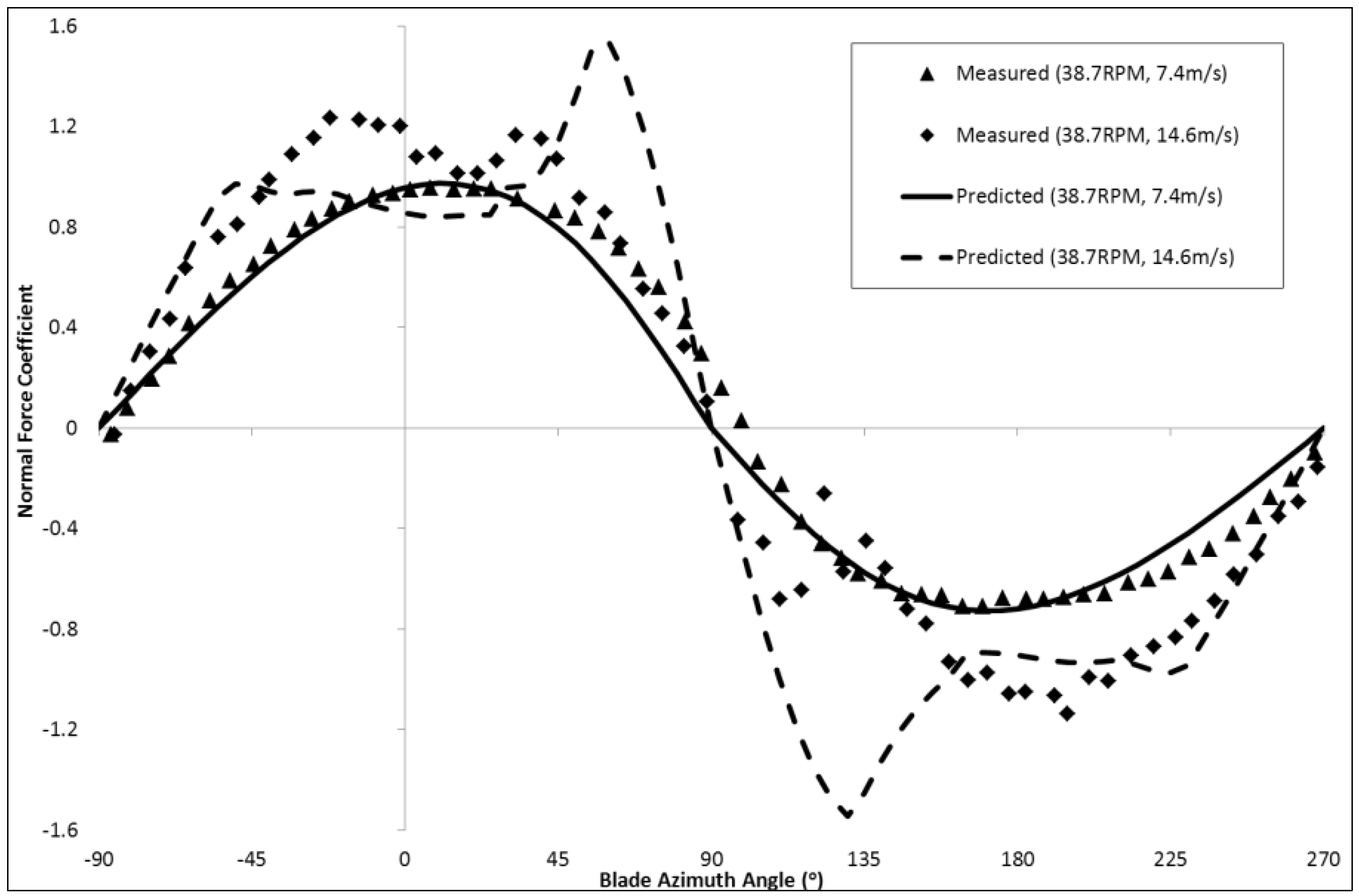
Equatorial loads were also evaluated by SNL based on blade surface pressure measurements [
29] and the variation of measured normal force coefficient with blade position is shown in
Figure 7 for wind speeds of 7.4 m/s and 14.6 m/s (38.7 rpm). At the lower wind speed the flow is attached and the performance model mostly shows good agreement. For negative pitch rates the normal force coefficient,
CN, is under-predicted. Momentum theory suggests that
CN = 0 when the blade is parallel with the wind direction (
i.e., for blade azimuth positions −90°, +90°, and +270°) for an untwisted symmetric blade section, but experimental data indicates that this is not the case indicating a lag effect that is not modeled using the present model.
Figure 7.
Sandia 17 m Φ-rotor variation of equatorial normal force coefficient with blade position (38.7 rpm).
Figure 7.
Sandia 17 m Φ-rotor variation of equatorial normal force coefficient with blade position (38.7 rpm).
At the higher wind speed the blade encounters flow separation and DS and although the features are captured by the model, the C
N magnitude is not well matched, corresponding to an under-prediction of power at this wind speed and the slightly higher rotational speed of 42.2 rpm (see
Figure 6).
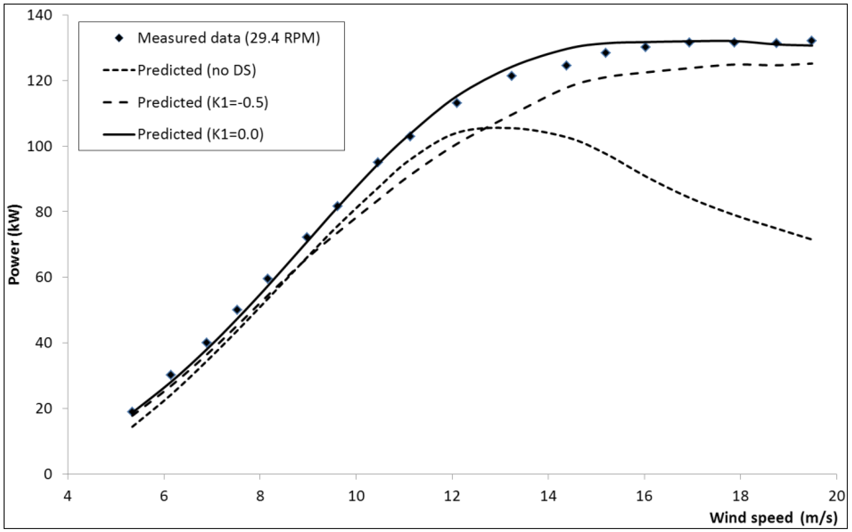
The performance model has also been evaluated for another troposkien Φ-shaped VAWT with the thicker NACA0018 section. Between 1976 and 1986, the Institute de Recherche de l’Hydro Quebec in cooperation with the NRC installed and operated an experimental 230kW Φ-rotor on the Magdalen Islands in the Gulf of St. Lawrence, Quebec. Turbine geometry and measured power data is published by Templin and Rangi [
30]. Predicted and measured power is presented in
Figure 8 and
Figure 9 for rotational speeds of 29 and 37 rpm respectively. At the lower rotational speed the effects of DS are significant with the proposed modification to the Gormont model and a Masse coefficient,
AM = 3.6, giving good agreement with measured power. The original Gormont model results in an under prediction of power.
Figure 8.
NRC 24m Φ-rotor power vs. wind speed at 29.4 rpm.
Figure 8.
NRC 24m Φ-rotor power vs. wind speed at 29.4 rpm.
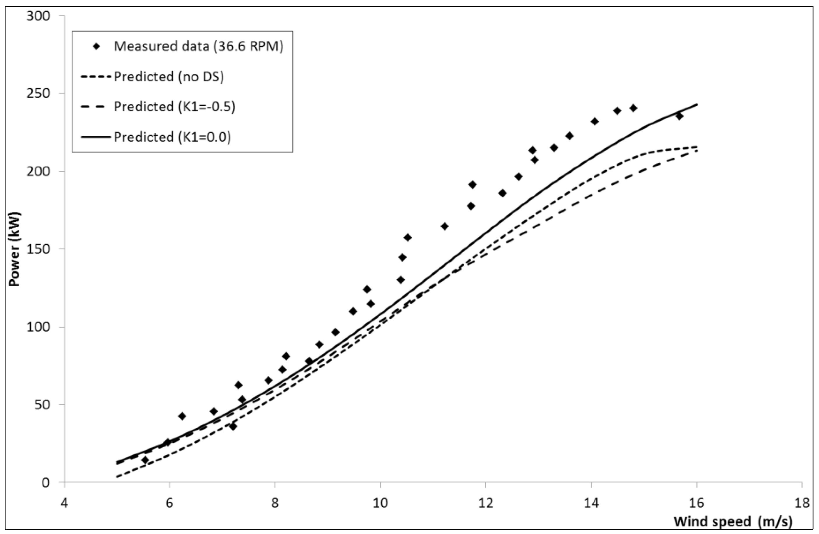
Figure 9.
NRC 24m Φ-rotor power vs. wind speed at 36.6 rpm.
Figure 9.
NRC 24m Φ-rotor power vs. wind speed at 36.6 rpm.
At the higher rotational speed, the predicted power is still in reasonable agreement with measured data but is under-predicted compared with that for the lower rotational speed. Also, DS has a much lesser effect on power at this condition.
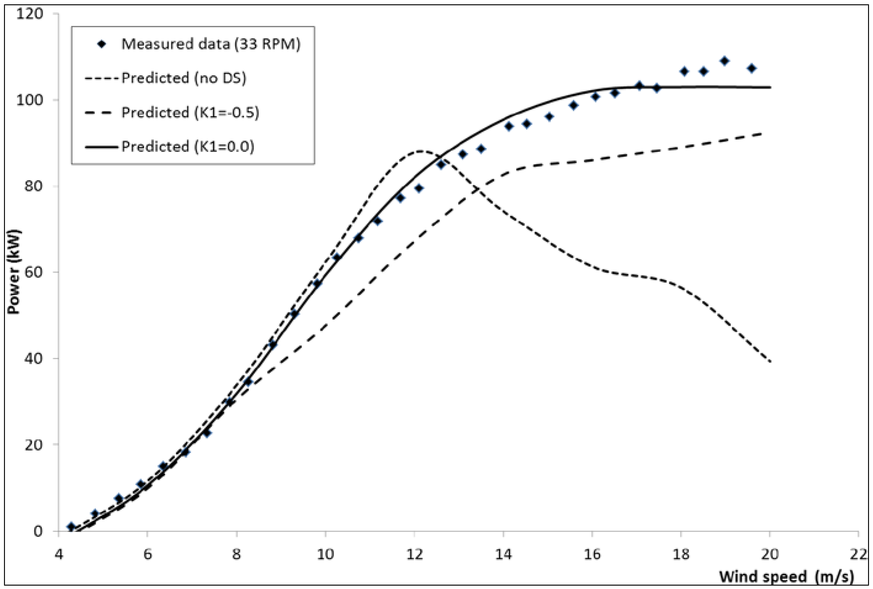
In the UK VAWT Ltd constructed a series of 2-bladed H-rotors including the VAWT-450, a 25 m diameter research rotor installed at Carmarthen Bay in Wales in 1986. Turbine model results significantly under-predict power for this turbine, a trend also reported by Anderson
et al. [
31] using their own model that was attributed to manufacturing defects of the blade profiles. Consequently, results for this turbine are not included in this paper. VAWT Ltd. subsequently installed a commercial 20 m diameter VAWT-260 turbine that operated on the Scilly Isles from 1988 to 1992 with a rated power of 105 kW. Turbine geometry and measured power data is published by Morgan
et al. [
32].
Figure 10 shows the predicted and measured power for the VAWT-260 turbine, with a Masse coefficient,
AM = 6. Clearly dynamic stall has a significant effect on power for wind speeds above ~8 m/s. Furthermore, the suggested modification of
K1 = 0 for negative pitch rates gives an improved comparison of power over most wind speeds, with the value suggested by Gormont (
K1 = −0.5) under-predicting power.
Figure 10.
VAWT-260 H-rotor power vs. wind speed at 33 rpm.
Figure 10.
VAWT-260 H-rotor power vs. wind speed at 33 rpm.
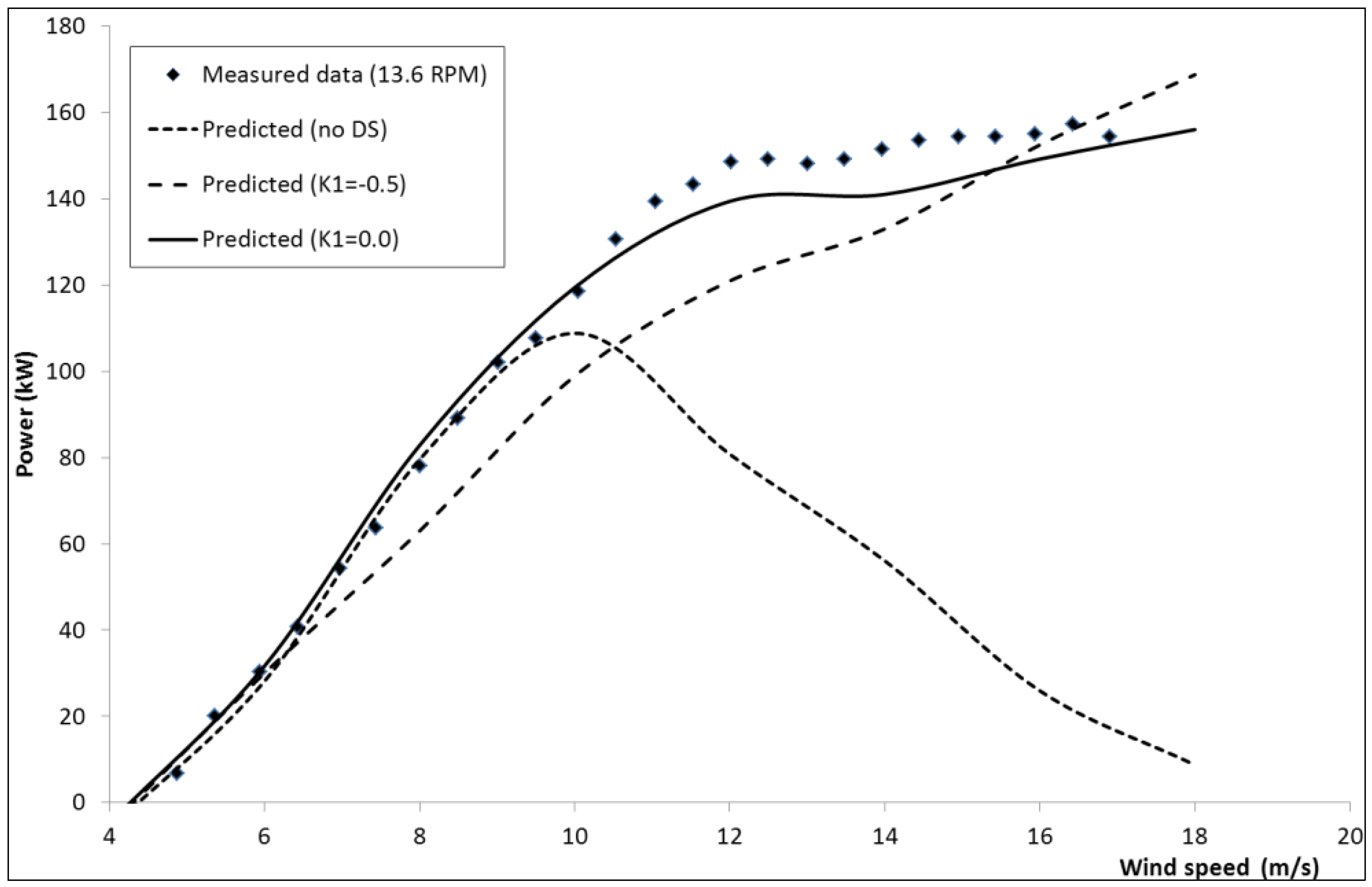
VAWT Ltd also constructed a larger 35m diameter VAWT-850 H-rotor at the Carmarthen test site with a rated power of 500 kW which operated between 1990 and 1991. Turbine geometry and measured power data is published by Mays
et al. [
33]. Measured data is only available for the lower operating rotational speed of 13.6 rpm and is compared with predicted results in
Figure 11. The figure again shows that DS is significant for wind speeds above ~9 m/s and that with a higher Masse coefficient,
AM = 11, a good representation of the power curve shape is achieved and reasonable agreement of peak power. As for the smaller VAWT-260 H-rotor the proposed modification to the Gormont model improves the prediction of power relative to the original implementation at all wind speeds above 6 m/s.
Figure 11.
VAWT-850 H-rotor power vs. wind speed at 13.6 rpm.
Figure 11.
VAWT-850 H-rotor power vs. wind speed at 13.6 rpm.
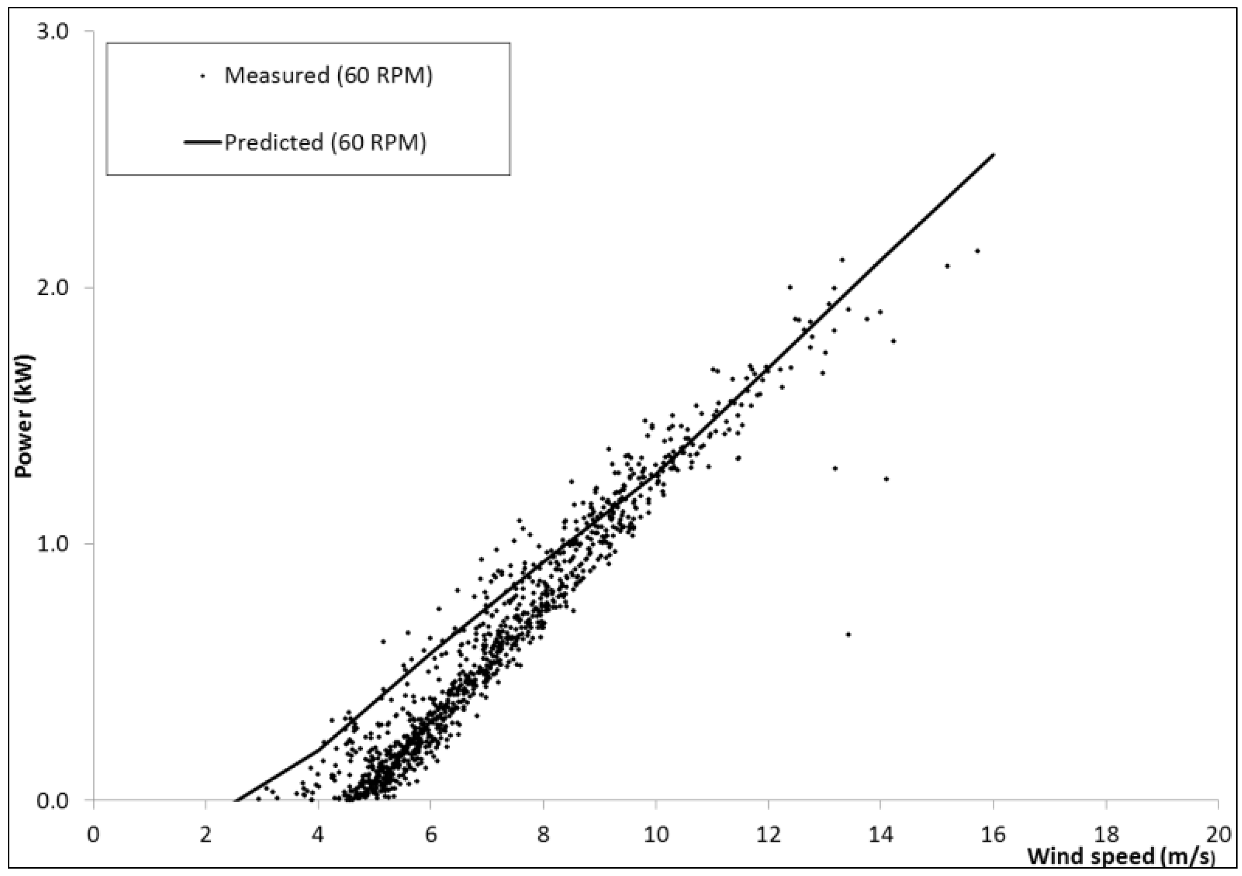
In addition to evaluating the aerodynamic performance model against measured data for “conventional” VAWTs, the model has also been used to predict power generated by the novel turbine pictured in
Figure 1 with NACA 0015 blade sections. These results are shown in
Figure 12 for a rotational speed of 60 rpm using
AM = 6. Although there is some scatter in the measured data there is a clear trend that is reasonably well predicted except at low wind speeds. This 5 kW prototype is not efficient due to the large losses from multiple junctions and the induced drag and lift losses from the low aspect ratio blades. Using the present performance model within a multi-disciplinary optimisation procedure the concept was developed for a 10 MW offshore VAWT. These designs proposed a novel “sycamore” shaped rotor with fewer high aspect ratio blades, and the potential to lower the cost of energy compared with conventional offshore turbines and was described in detail in [
34].
Figure 12.
NOVA prototype rotor power vs. wind speed at 60 rpm.
Figure 12.
NOVA prototype rotor power vs. wind speed at 60 rpm.
4. Discussion and Recommendations
The complex nature of dynamic stall presents a significant challenge for modeling VAWT performance using low order momentum models. However, the Gormont DS model with modifications has provided reasonable agreement with measured power by mimicking the effective pitch angle under dynamic conditions and therefore the hysteresis response in lift produced. Whilst a number of other VAWT BEM research codes exist, their evaluation has generally been limited to a consideration of either Φ- or H-rotor machines. This paper describes a more extensive evaluation campaign using data from five medium to large VAWTs with both Φ- and H-rotor shapes and a total of 9 operating conditions. In the majority of these cases the model gives good agreement with the measured mechanical power over the range of wind speeds considered, using the recommended settings for the DS model.
The different DS characteristics observed for the SNL 34 m diameter turbine are likely to be attributable to the NLF sections that are used for most of the blade length, as suggested by Masson
et al. [
18]. In contrast the other VAWTs considered in this study have adopted turbulent section designs and the positive influence of DS on the power produced at moderate to high wind speeds can be significant. Designs of NLF sections adopt a very different philosophy to that of turbulent sections. Adverse pressure gradients transition the boundary layer. Hence to maintain laminar flow the leading edge suction peak is further aft leading to reduced favorable pressure gradients and significantly lower suction levels at the leading-edge. The elimination of a suction peak at the leading edge may be significant in avoiding the vortex shed at higher angles of attack and pitch rates that provides the lift augmentation associated with DS. For VAWT rotors with NLF section designs it is therefore recommended that DS corrections are not included.
For the performance of the SNL 17 m diameter rotor with NACA 0015 sections the present model adopts the DS model settings recommended by Berg [
15] and Masson
et al. [
18] with a Masse coefficient,
AM = 6, giving good agreement with measured power except at higher wind speeds. Masson
et al. [
18] suggested that the Masse damping coefficient is a function of the blade aerofoil geometry and in particular the thickness/chord ratio, recommending
AM = ∞ for the NRC/Hydro-Quebec 24 m diameter Φ-shaped turbine with the thicker NACA 0018 section. The present study would suggest that for this section, an appropriate Masse coefficient is also a function of the blade chord (
c). Results also indicate that DS is more significant for the H-shaped rotors than for the Φ-shaped rotors, and particularly for the VAWT-850 machine, though the configuration shape does not influence the damping coefficient. For the three turbines considered with the NACA 0018 section, the optimum Masse damping coefficient can be approximated using:
Since only one turbine with the thinner NACA 0015 section was evaluated, the variance of Masse coefficient with chord cannot be determined. Recommended damping coefficients are summarised in
Table 1 for all of the turbines considered.
A further recommendation of this study is that the dynamic lift and drag increments associated with DS should be limited when the blade section is travelling towards the zero angle of attack position,
i.e., for negative pitch rates. This modification to the original Gormont model is implemented using Equation (22) for the calculation of the effective angle of attack rather than Equation (7) recommended by Gormont. The effect of this modification on power curves is significant, particularly for power curves shown in
Figure 8,
Figure 10 and
Figure 11. The increase in gradient of the power curves between wind speeds of approximately 6m/s and 8m/s observed in measured data is predicted using this modification and not with the original Gormont model and is particularly evident for the H-shaped rotors. This observation might be explained by higher turbulence levels that are experienced by the blade section for negative pitch rates relative to positive pitch rates which are known to influence DS. Based on water tunnel experiments, Brochier
et al. showed that a Φ-shaped rotor creates significant turbulence between the blade azimuth positions of +15° and +135° and consequently suggests that neglecting DS over this segment improves predictions of rotor power [
28]. Over this segment the blade is retreating and the pitch rate is mostly negative. However in the present model DS is also neglected for the advancing blade experiencing negative pitch rates, which was found to give a better prediction of rotor power than using the Brochier method.
Results presented in
Figure 6 for the SNL 17m diameter rotor however, indicate that a thinner blade section has different DS characteristics, with the original Gormont implementation and
giving better performance prediction. Due to the apparent dependence on both blade t/c and chord further analysis is required if alternative turbulent sections to those considered in this study are to be used for VAWT designs. Cranfield University is currently installing a 19 m diameter H-rotor with NACA 0015 blade sections and a rated power of 50kW. Measured torque and surface pressures will be used to further validate the turbine model and understand DS mechanics.


