Energy-Regenerative Braking Control of Electric Vehicles Using Three-Phase Brushless Direct-Current Motors

Abstract
: Regenerative braking provides an effective way of extending the driving range of battery powered electric vehicles (EVs). This paper analyzes the equivalent power circuit and operation principles of an EV using regenerative braking control technology. During the braking period, the switching sequence of the power converter is controlled to inverse the output torque of the three-phase brushless direct-current (DC) motor, so that the braking energy can be returned to the battery. Compared with the presented methods, this technology can achieve several goals: energy recovery, electric braking, ultra-quiet braking and extending the driving range. Merits and drawbacks of different braking control strategy are further elaborated. State-space model of the EVs under energy-regenerative braking operation is established, considering that parameter variations are unavoidable due to temperature change, measured error, un-modeled dynamics, external disturbance and time-varying system parameters, a sliding mode robust controller (SMRC) is designed and implemented. Phase current and DC-link voltage are selected as the state variables, respectively. The corresponding control law is also provided. The proposed control scheme is compared with a conventional proportional-integral (PI) controller. A laboratory EV for experiment is setup to verify the proposed scheme. Experimental results show that the drive range of EVs can be improved about 17% using the proposed controller with energy-regeneration control.1. Introduction
With the emergence of energy crisis, ways of reducing air-pollution have become the great challenge. Nowadays, fossil-fueled automobiles have become the major transportation tools. Automakers have made a great effort to find green, energy saving and zero pollution transportation tools. Thus, electric vehicles (EVs) have grown at an accelerated pace lately [1–3]. However, some of the main difficulties for commercialization of EVs such as driving range still remain. Long time for charging battery pack and short distance of driving range are the major problems for EVs. Effective battery utilization and advanced motor control have become an important issue for EVs [4–6].
A pure electric vehicle (PEV) contains three major parts: the power battery pack (usually in series as an energy-storage unit), the driving motor [can be induction motor (IM), brushless direct-current motor (BLDCM) and switched reluctance machine (SRM) [7], etc.], and the power converter controller. Among all the driving motors, the brushless direct-current (DC) motor has many advantages over other brush DC motors, IMs and switch reluctance machines. It has the merits of simple structure, high efficiency, electronic commutating device, high starting torque, noiseless operation and high speed range, etc. Hence, the brushless DC motor has been widely used in EVs [8,9]. Conventional EVs use mechanical brakes to increase the friction of the wheel for deceleration purposes. Thus, the braking kinetic energy is wasted. With this problem in mind, this paper will discuss how to convert the kinetic energy into electrical energy that can be recharged to the battery pack. As a result, regenerative braking can realize both electric braking and energy savings.
So far, many articles have illustrated the regenerative braking technique of EVs [2,3,10,11]. Khastgir [12] presented a novel method for implementing a regenerative brake strategy without changing the existing mechanical brake system of a low cost conventional vehicle which is converted to a low-cost hybrid electric vehicle (HEV) for front axle applications, i.e., without adding complex electronic systems like anti-locked braking system (ABS). The results show a potential of 30% of brake energy recovery with the proposed strategy. Sankavaram [13] proposed a systematic data-driven process for detecting and diagnosing faults in the regenerative braking system of HEVs. Their results demonstrate that highly accurate fault diagnosis is possible with the pattern recognition-based techniques. A robust H2/H∞ controller is put forward for a battery EV [14,15], the experimental results demonstrate that the driving range can be improved 4% when using H∞ controller instead of traditional proportional-integral (PI) controller, which demonstrate that H∞ controller can recovery more energy than PI controller under the same operations. However, the implementation of H∞ controller needs complex mathematic computations. Considering the uncertain parameters while modeling the system, a robust state feedback H∞ controller is also provided [16].
From the aforementioned state-of-art on regenerative braking, these technologies can be categorized as: (1) regenerative braking is realized by using the additional energy storing components (ultra-capacitor pack) to absorb the instantaneous braking energy. Thus, the battery pack and ultra-capacitor form a hybrid power supply system (HPSS), and the descriptions of HPSS can be found in [17–19]; (2) in order to improve the DC-link voltage of the power converter, a bidirectional DC-DC power converter is used for boosting control [20,21]; (3) braking energy is recovered by using the driving power converter itself for charging control, the energy-regeneration control is achieved by using different control strategy, this can be found in [22,23]. For Category (1), the additional energy-storing components need to be charged and discharged via a DC-DC power converter, status of the ultra-capacitor (such as full charged or under-voltage) needs to be acquired, thus, voltage and current sensors must be installed in the controller, in this way, the braking energy is temporarily stored in the ultra-capacitor pack, this scheme makes the whole system more complicated, moreover, due to the high price of ultra-capacitor pack, the cost of the controller would be more expensive than a conventional controller. For Category (2), since the back electromotive force (BEMF) is much lower than the battery's terminal voltage, even at high speed, thus, the BEMF also needs to be boosted for charging the battery pack. Some of the controllers achieve this goal by adding an additional buck-boost controller. The best way, in our opinion, to realize this goal, is by using the controller itself.
To summarize the aforementioned methods, this paper will concentrate on the ways of realizing regenerative braking technology by employing a robust sliding mode controller. Compared with conventional control methods, parameter variations and disturbance are considered in the design of the proposed robust controller. Comparisons on the driving range of EVs using different controllers have been implemented. The output of the controller determines the switching state of the power transistors in the converter. This paper is arranged as follows: in Section 2, we explain the system configuration and dynamic model of EVs. The mechanical structure of the whole vehicle is also illustrated, and based on that, operation principle and equivalent power circuit under regenerative braking control are elaborated in detail. In Section 3, a mathematical model of the power circuit based on Kirchhoff's laws is set up, considering that un-modeled parameters and disturbance might occur in utility application, a robust terminal sliding mode (TSM) controller has been designed to overcome drawbacks in the state-space equation of the system, stability and reliability of the system are analyzed and demonstrated. In Section 4, simulation work has been performed to verify the feasibility and validity of the proposed scheme. In Section 5, in order to verify the utility of the proposed scheme, a laboratory hardware platform of EVs has been set up to validate the performance of the proposed controller. Finally, conclusions and suggested future works are also presented.
2. Regenerative Braking System for Battery Powered EV
In this section, we first give the system configuration of the EV, then, a dynamic model of EVs with the given parameters and used for simulation is established. Based on this, analysis of the schematic diagram and operation principle of the power circuit in regenerative braking mode are given. Finally, a robust sliding mode current controller for phase current and DC-link voltage is provided.
2.1. System Configuration
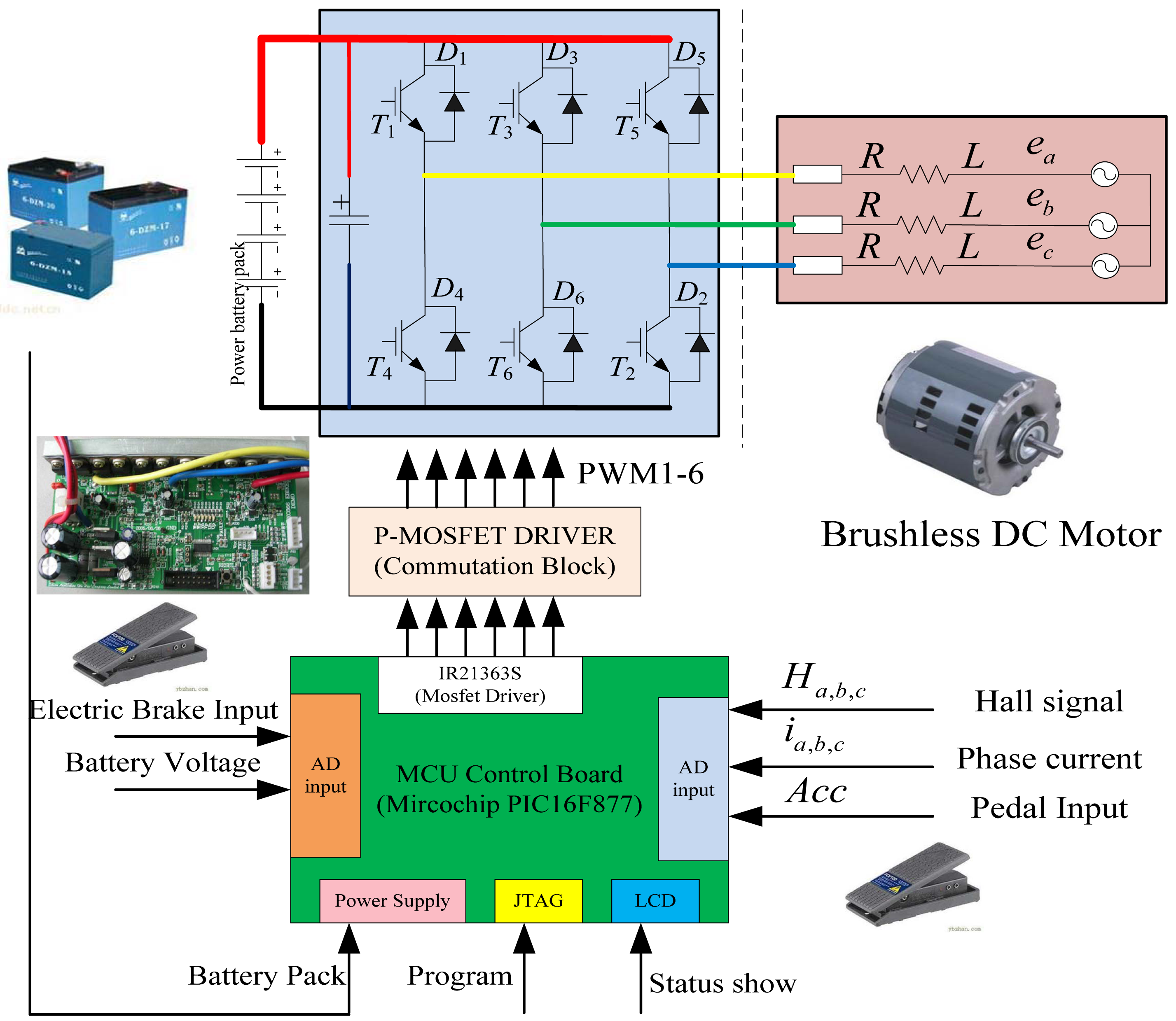
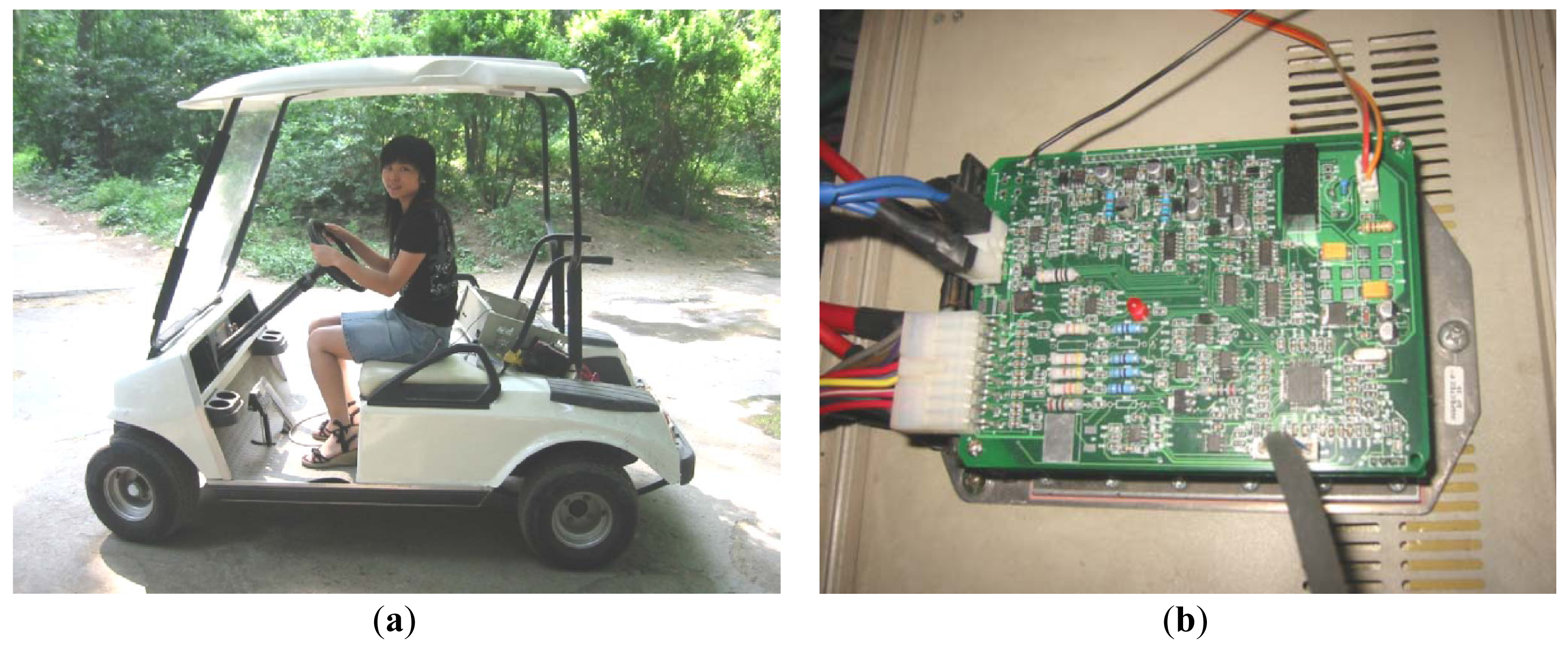
Figure 1 illustrates the system configuration of the electric golf cart. It can be clearly seen that it contains a power accumulator battery pack, a half-bridge three-phase voltage source converter (VoSC), a hub permanent magnetic brushless DC motor. For the additional parts, there are two pedals, one is responsible for acceleration, the other is in charge of electric brake control, both of them would input an adjustable voltage ranging from 0 V to 5 V. Hall signals are given to provide the position information of the rotor. Two sensors are adopted to acquire the phase current of the inverter. Status show panel liquid crystal display (LCD) block, programming interface, a MOSFET driver integrated circuit (IC) (typed as: IR21363S, IR Company, Orlando, FL, USA), and signal regulation circuit are also equipped in the controller design. A microcontroller (typed as PIC16F877 from Microchip Company, Chandler, AZ, USA) is chosen as the core control IC for function realization and complicated control algorithm implementation.
It is obvious that the electrical regenerative braking system of the EVs cannot handle such a large amount of braking power, Hence, a mechanical friction braking system must be adopted to guarantee safe braking. Moreover, to prevent from a failure operation of the electric energy regeneration, or, in case of an emergency, the mechanical friction braking system is an indispensable part of the system.
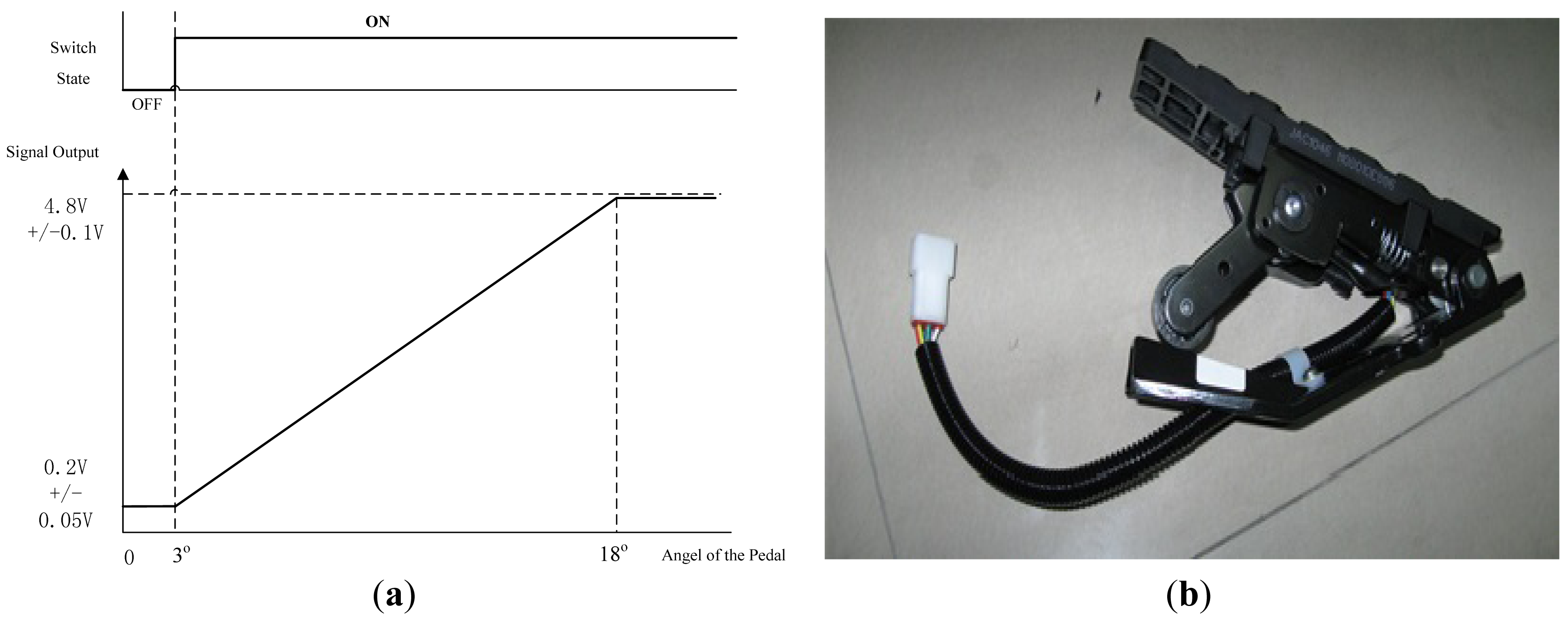
Due to the above reasons, some EV enterprises integrate the electric braking and friction braking functions in one brake pedal. Operation principle and mechanical structure of the braking pedal are shown in Figure 2. From the signal output shown in Figure 2a, we know that when the pedal's angle ranges from 0 ° to 3°, its output voltage is closed to 0.2 V, when the brake pedal's angle varies from 5° to 18°, its corresponding output voltage increase from 0.2 to 4.8 V, the output voltage is almost in proportional to the braking angel. When the braking angel is over 18°, which means that the driver wants an emergent braking, mechanical braking system will function at this moment. Figure 2b shows the diagram of the mechanical structure and installation guide of the brake pedal.
2.2. Dynamic Model of the EVs
Assuming that the resistance of EVs in motoring operation can be summarized as: air resistance Fω, rolling resistance Ff, climbing resistance Fi and acceleration force Fm. Expressions of the air resistance, rolling resistance and climbing resistance are:
In Equation (1), Cd is the coefficient of air resistance, A is windward area, ρ denotes the air density, vr is the relative speed between the vehicle and the air, f is the coefficient of rolling resistance, m is the total weight of the vehicle, α is the maximum climbing angle, δ denotes the rotation weight coefficient of the vehicle, m is the total weight of EVs, and a is the acceleration speed of the vehicle. Hence, the load torque on the tire during motoring operation would be:
In Equation (2)Rw stands for the radius of the tire, assuming that the transmission ratio between the tire and motor is Kg, the total load torque TL would be:
Output electromagnetic torque of motor is Te, the motion equation would be:
Expression about the equivalent moment of inertia in Equation (4) is:
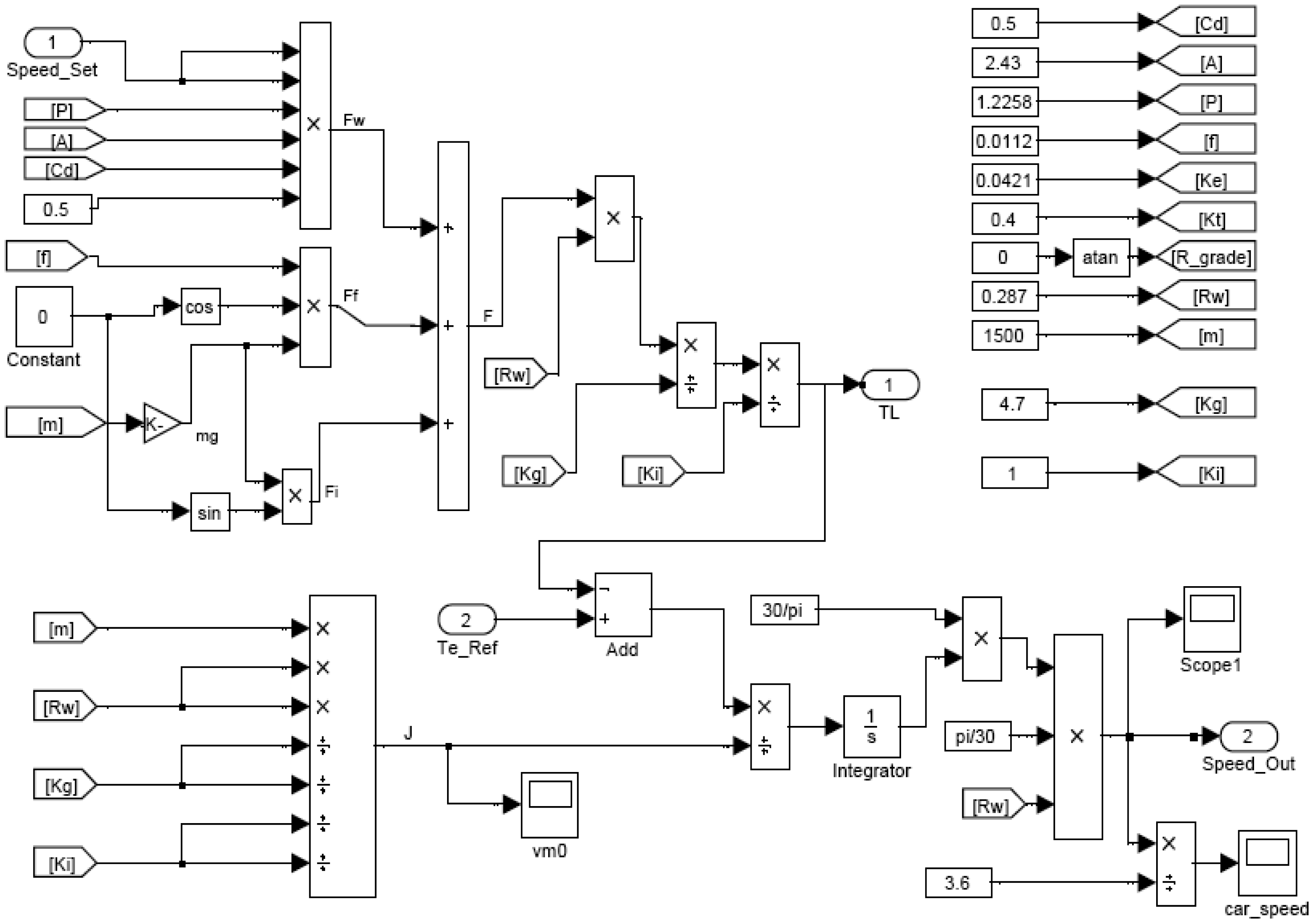
Figure 3 illustrates the block diagram of the control system for EVs using the SimPowerSystem toolbox in Matlab, and parameters used in the simulation are chosen as: Cd = 0.5, windward area A = 2.43 m2, coefficient of rolling resistance f = 0.0112, BEMF coefficient Ke = 0.0421, torque constant Kt = 0.4, air density ρ = 1.225 kg/m3 N·s2·m4, m = 1500 kg, the transmission ratio Kg = 4.7, Ki = 1, the tire radius Rw = 0.287 m, climbing angle α = 0, the initial relative speed between the air and vehicle vr = 0.
2.2. Schematic and Operation Principle of Regenerative Braking
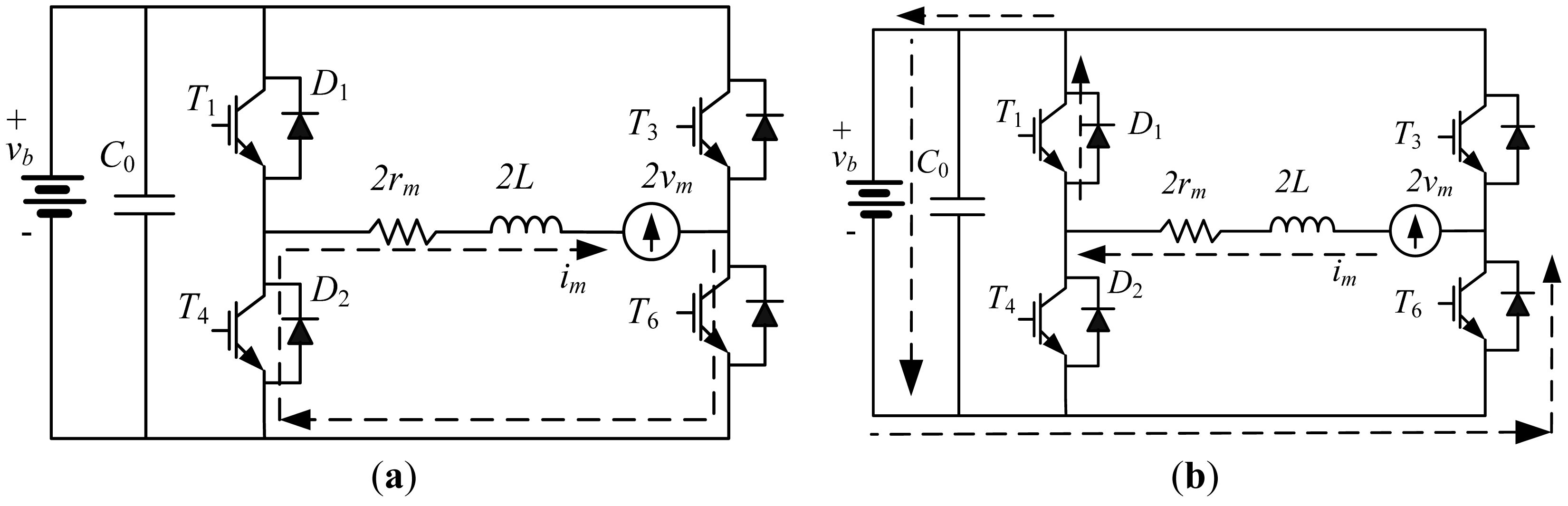
Figure 4 gives the equivalent circuit and control block diagram of the EV using BLDCM. Considering that the motor operates in regenerative braking mode, the BEMF of the motor is lower than the battery pack's terminal voltage, even when EVs runs at high speed, in order to charge the battery pack, DC-link voltage of the power converter must be higher than the batter pack's terminal voltage, thus, BEMF voltage of the motor must be boosted, a bidirectional buck-boost power circuit is needed in this circumstance. The three-phase VoSC can be used as a driver in motor operation and a generator in braking control. Thus, compared with conventional method, no additional power converter is needed. The switching table of the power transistors for boosting is provided. The switch state of the upper power transistors is decided by the Hall signal sequence of the motor. Table 1 shows the detailed information of the switching table in regenerative braking mode control. From Table 1, we can see that the three power transistors are conducted simultaneously; each power transistor conducts 180° in one cycle, compared with traditional two power transistors conduction mode shown in Table 2, the synthesized output torque can be improved about 88.235%. The phase-to-phase change point varies every 60°, the output state of the hall signal changes every 60°. Theoretically speaking, there are totally six sectors in one loop.
In order to acquire the state-space equation of the system, assuming that the resistance, inductance and BEMF of three-phase BLDCM are symmetrical, from Figure 4a, we can see that when T4 is ON, bypass diode D6, T4 and the motor form a closed circuit, the braking energy is temporarily stored in the inductance. When T4 is OFF, bypass diode D1, T6 and the battery form another closed circuit. The battery is charged by the boosted voltage. Charging current can be controlled by the regulation of duty cycle in pulse-width modulation (PWM) control.
Assuming that the state variable x includes the inductance current iL and terminal voltage vc on the DC-link capacitors, which means x = [iL vc], Internal resistance of the battery is rb, From Figure 4a, Kiandhoff voltage law (KVL) equation of the closed circuit can be concluded as:
In Equation (6), C is the DC-link capacitance, vb is the battery voltage, and L is phase inductance of the windings in BLDCM. thus, the dynamic state-space equation when T6 is ON would be:
From Figure 4b, when T4 is OFF (dT ≤ t ≤ T), using the same way, the KVL equation of the closed circuit would be:
Hence, the dynamic state-space equation when T4 is OFF would be:
As is known, expressions of the small signal model equation considering disturbance are:
In Equation (10), A′ = DA1+D′A2, B′ = DB1 + D′B2, C′ = DC1 + D′C2, x = X + x̂, u = U + û, d = D + d̂ and D′ = 1 − D.
After the perturbation process and instantaneous variable separation, the averaged small signal model of the system [20,24] would be:
3. Sliding Mode Controller Design for the Regenerative Braking System
From the state-space equation illustrated in Equation (11) in the former section, there are uncertain parameters in the dynamic system, such as the internal resistance rm and inductance L of the windings in BLDCM. The parameter uncertainties include the tolerance of the elements which constitutes the converter. These variations often occur due to temperature change and unavoidable measurement errors. Sliding mode control, which is well known for its robustness and invariance, has been widely applied in aircraft control, motor control and power converter devices. Hence, in this section, we will first give a brief introduction on sliding mode control (SMC), then, the sliding mode torque and flux controller will be designed and implemented.
3.1. Introduction on Sliding Mode Control
Sliding mode control, also named variable structure control (VaSC), was evolved from the pioneering work of Emel'yanov and Barbashin in Russia in the early 1960s; a survey paper by Utkin was published in English [25], and thus, SMC became known outside Russia. VaSC concepts have subsequently been utilized in the design of robust regulators. It has advantages of high efficiency in improving the disturbance rejection and robustness properties over other control methods. Yet, the conventional sliding mode controller employs a linear sliding surface; therefore, convergence rates of such methods can be exponential with infinite settling time. In order to overcome the reachability deficiency in conventional sliding mode controller, a non-linear sliding mode surface which is called TSM is proposed. The TSM can ensure the finite-time convergence of states during the sliding mode stage. Thus, TSM control can guarantee that all the stave variables are convergent to the origin at finite-time. The merits of TSM have been demonstrated to have better performance on robustness and disturbance rejection properties.
3.2. Sliding Mode Flux and Torque Controller Design
Since we have obtained the state-space model of the boost converter in Equation (11), the next stage is the derivation and design of the controller. For the above system, the control law using a switching function can be expressed as:
In Equation (12), s represents the sliding surface and the instantaneous state variable's trajectory, the s-function can be described as:
Substituting A′, E, B′ and C from Equation (11) into Equation (14), the small-signal equivalent input voltage would be:
Since the power converter operates in continuous current mode (CCM), the duty ratio control D can be calculated as D = ueq/vm.
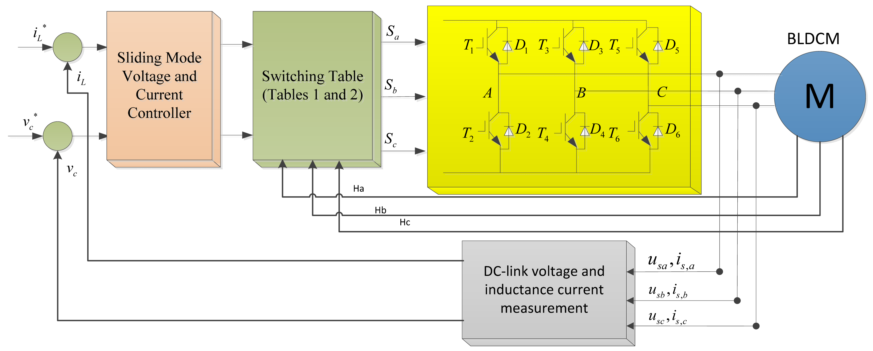
For BLDCM, in every 60° area, the output torque is in proportional to the phase current, thus, the inductance current iL and DC-link voltage vc are chosen as the outer loop. The control block diagram of the system in regenerative braking mode is shown in Figure 5.
4. Experimental Results
4.1. Hardware Platform Description
In order to confirm the utility of the proposed system, a laboratory experimental prototype for an electric golf cart is developed. The power circuit of the three-phase half bridge converter consists of six N-channel Power MOSFETs (P75NF75), and an integrated bootstrap MOSFET driver from International Rectifier (IR-21363S), Mechanical and electrical specifications of the whole system used in experiment are shown in Table A1 in the appendix. System configuration of the electric golf cart is illustrated in Figure 6. Two current sensors (LT108-S7) are used in the controller for over-current and torque output control. A total of six PWM signals are used, the PWM modulation frequency is set to be 16 kHz, and dead-time for upper and lower power transistor is set to be 4 μs to prevent a direct-through current.
4.2. Experimental Results and Analysis
In this section, we will provide the experimental comparison results by using conventional PI controller and the proposed sliding mode controller, respectively. Time response of the output torque and torque ripple under different speed are provided. A constant braking torque for energy-regeneration is emulated by adding a magnetic powder brake in the system.
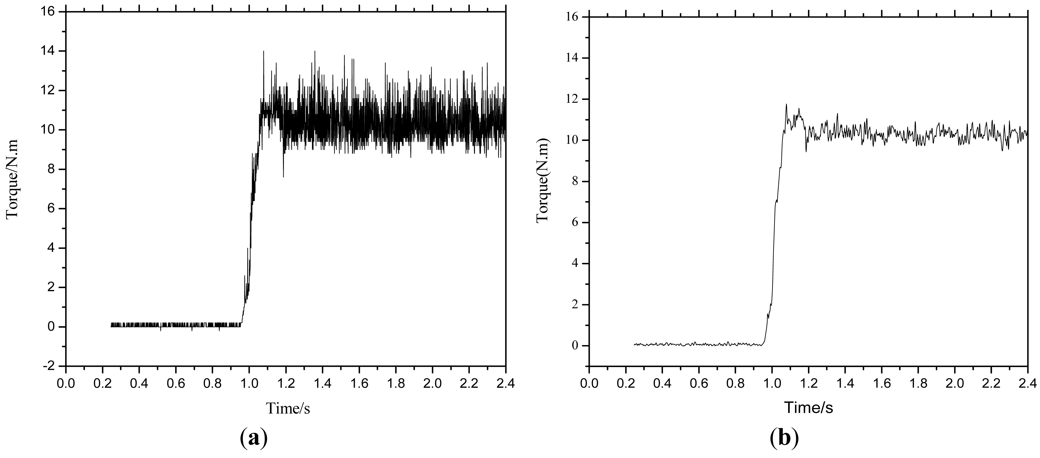
From Figure 7, when the braking torque is given at low speed n = 200 rpm, load torque TL = 10 N. m, we can see that both method could obtain good dynamic braking torque response. The rising time is about 100 ms.
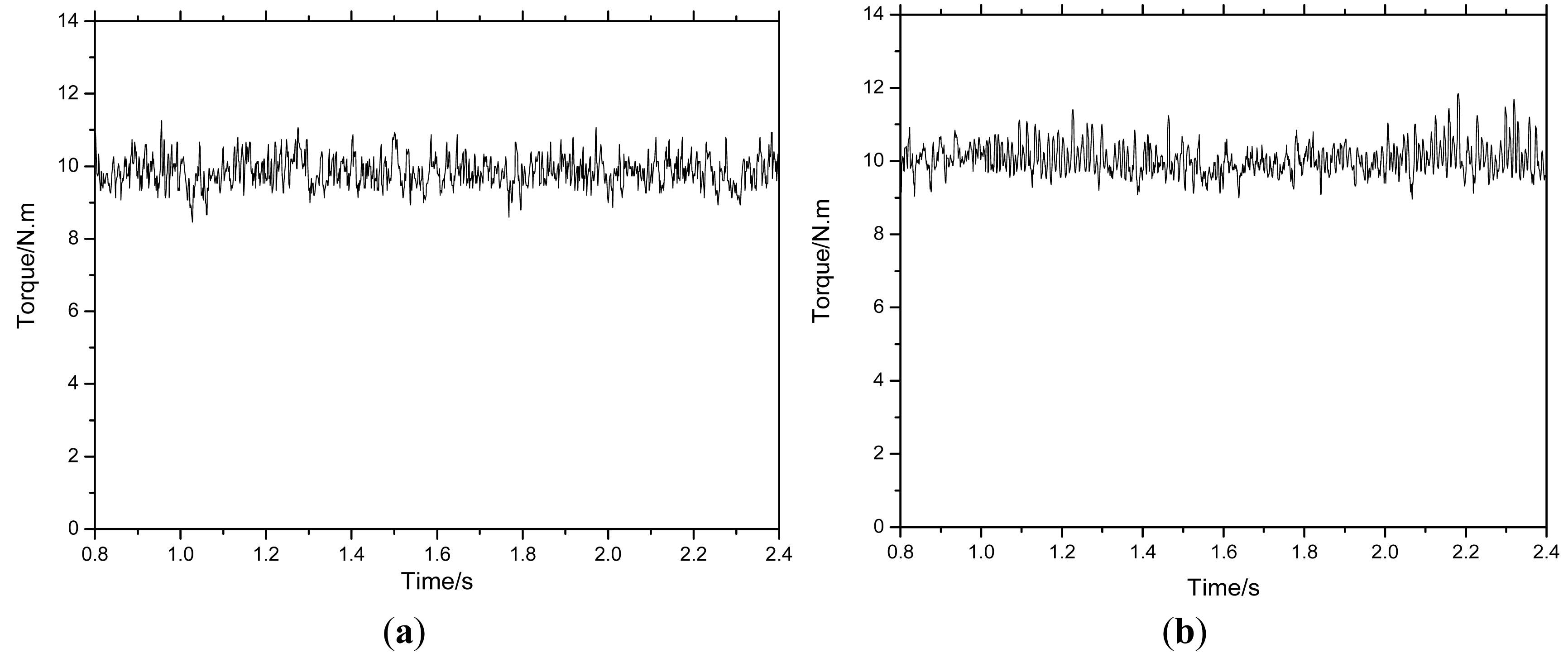
From Figure 8, we can acquire that the torque variations range from 9.0 N. m to 11.0 N. m for PI controller and from 10.0 N. m to 10.5 N. m for sliding mode controller, which demonstrate that the proposed controller has much smaller torque ripple than conventional PI controller. From the mathematical model aforementioned in the previous parts, we can conclude that this is due to the voltage drop of the motor's internal resistance which cannot be ignored at low speed.
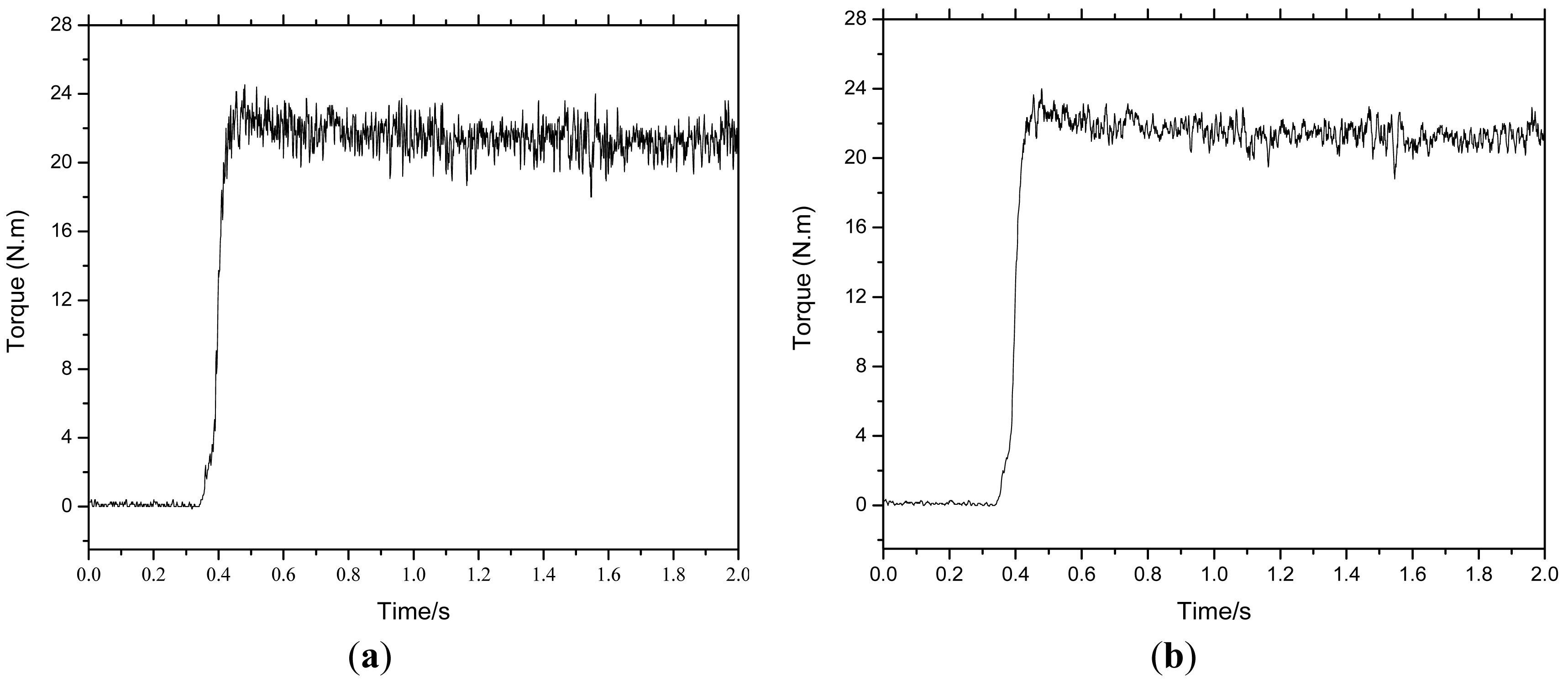
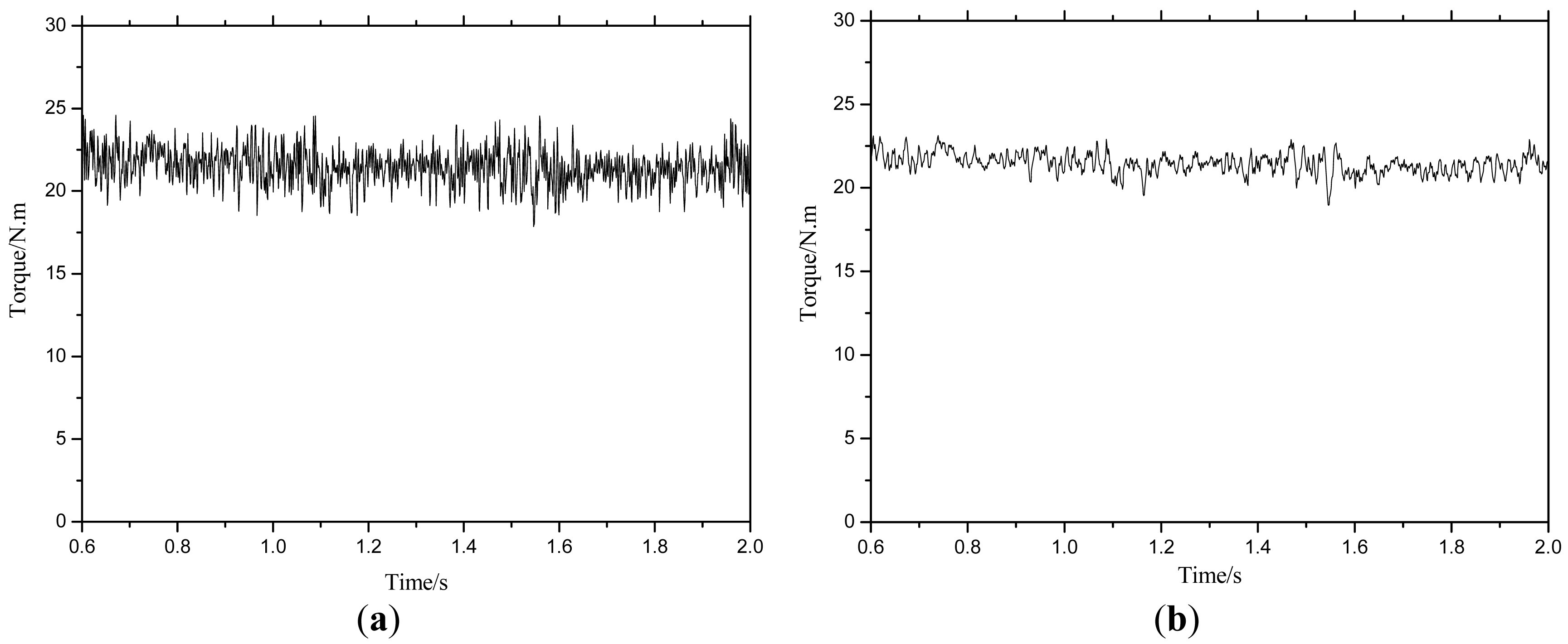
From Figure 9, when the braking torque is given at high speed n = 1000 rpm, and the load torque TL = 20 N. m, both PI and SMC controller can obtain good dynamic torque response.
From the steady state of the output torque error which is shown in Figure 10, the torque ripples for both methods are nearly the same, which is due to the omission of the voltage drop's effect on the motor's internal resistance which can be ignored at low speed.
Performance comparisons are made between the PI and sliding mode control. The driving range of battery powered EV is presented in Figure 11b with two approaches. Results show that the driving range was 56 km under the PI control when the battery pack's terminal voltage decreased from 54 V to 44 V. When using the proposed SMC controller, the driving range increased to 60 km, which is 7% higher than that of the PI controller. It is needed to note that the driving range is only 50 km without regenerative braking control. Therefore, the driving range can be improved at least 12% with regenerative control. This demonstrates the validity and superiority of the proposed scheme.
5. Conclusions
Regeneration braking can minimize the wear of the brake pads, extend the driving range of EVs and reduce the maintenance cost significantly. Operation principle and equivalent power circuit of EVs under regenerative braking control are described in this paper. To overcome the influence due to the uneven system parameters, temperature change and disturbance, a robust sliding mode current controller is designed. Reachability, sliding mode plane and stability of the system using the proposed controller are put forward and demonstrated. Performance of the suggested controller is validated by experiments. Experimental results demonstrate that the proposed scheme could achieve good dynamic performance and robust stability, and the driving range could be improved by the proposed controller, which validates the correctness and feasibility of regenerative braking for battery powered EVs.
Acknowledgments
This work was simultaneously supported by the Fundamental Research Funds for the Central Universities of China (No. ZYGX2012J095), China Postdoctoral Science Foundation Funded Project (2013M542266), and also supported by the National Research Foundation of Korea (NRF) grant funded by the Korea government (MEST) (No. 2013-06-8127). The authors would like to thank all the reviewers for their advices and suggestions on improving this paper.
Conflicts of Interest
The authors declare no conflict of interest.
Appendix

| EV type | Electric bicycle | |
|---|---|---|
| Driving type | Rear wheel drive | |
| Motor parameters | Motor type | Hub BLDCM |
| Motor Power | 800 W | |
| Battery parameters | Battery type | Lead-acid |
| Battery capacity | 12 V/20 A h | |
| Number of battery in series | 4 | |
| Life cycle | - | |
| Weight | 6.7 kg × 4 | |
| Braking system | Without energy-regeneration | Mechanical brake |
| With energy-regeneration | Electric brake | |
References
- Chan, C.C. The state of the art of electric, hybrid, and fuel cell vehicles. IEEE Proc. 2007, 95, 704–718. [Google Scholar]
- Ehsani, M.; Falahi, M.; Lotfifard, S. Vehicle to grid services: Potential and applications. Energies 2012, 5, 4076–4090. [Google Scholar]
- Falahi, M.; Chou, H.M.; Ehsani, M.; Xie, L.; Butler-Purry, K.L. Potential power quality benefits of electric vehicles. IEEE Trans. Sustain. Energy 2013, 4, 1016–1023. [Google Scholar]
- Wang, X.; He, H.; Sun, F.; Sun, X.; Tang, H. Comparative study on different energy management strategies for plug-in hybrid electric vehicles. Energies 2013, 6, 5656–5675. [Google Scholar]
- Zheng, P.; Wu, F.; Lei, Y.; Sui, Y.; Yu, B. Investigation of a novel 24-slot/14-pole six-phase fault-tolerant modular permanent-magnet in-wheel motor for electric vehicles. Energies 2013, 6, 4980–5002. [Google Scholar]
- Khaligh, A.; Li, Z. Battery, ultracapacitor, fuel cell, and hybrid energy storage systems for electric, hybrid electric, fuel cell, and plug-in hybrid electric vehicles: State of the art. IEEE Trans. Veh. Technol. 2010, 59, 2806–2814. [Google Scholar]
- Omekanda, A.M. Switched Reluctance Machines for EV and HEV Propulsion: State-of-the-Art. Proceeidngs of the IEEE Workshop on Electrical Machines Design Control and Diagnosis (WEMDCD), Paris, France, 11–12 March 2013; pp. 70–74.
- Wu, H.; Cheng, S.-K.; Cui, S.-M. A controller of brushless DC motor for electric vehicle. IEEE Trans. Magnet. 2005, 41, 509–513. [Google Scholar]
- Wang, H.-P.; Liu, Y.-T. Integrated design of speed-sensorless and adaptive speed controller for a brushless DC motor. IEEE Trans. Power Electron. 2006, 21, 518–523. [Google Scholar]
- Shen, X.J.; Chen, S.; Li, G.; Zhang, Y.; Jiang, X.; Lie, T.T. Configure methodology of onboard supercapacitor array for recycling regenerative braking energy of URT vehicles. IEEE Trans. Ind. Appl. 2013, 49, 1678–1686. [Google Scholar]
- Yang, M.-J.; Jhou, H.-L.; Ma, B.-Y.; Shyu, K.-K. A cost-effective method of electric brake with energy regeneration for electric vehicles. IEEE Trans. Ind. Electron. 2009, 56, 2203–2212. [Google Scholar]
- Khastgir, S. The Simulation of a Novel Regenerative Braking Strategy on Front Axle for an Unaltered Mechanical Braking System of a Conventional Vehicle Converted into a Hybrid Vehicle. Proceedings of the 8th International Conference and Exhibition on Ecological Vehicles and Renewable Energies (EVER), Monte Carlo, Monaco, 27–30 March 2013; pp. 1–6.
- Sankavaram, C.; Pattipati, B.; Pattipati, K.; Zhang, Y.; Howell, M.; Salman, M. Data-Driven Fault Diagnosis in a Hybrid Electric Vehicle Regenerative Braking System. Proceedings of the IEEE Aerospace Conference, Big Sky, MT, USA, 3–10 March 2012; pp. 1–11.
- Ye, M.; Bai, Z.; Cao, B. Robust control for regenerative braking of battery electric vehicle. Control Theory Appl. IET 2008, 2, 1105–1114. [Google Scholar]
- Long, B.; Cheng, Y.Q. H∞ Robust Controller Design for Regenerative Braking Control of Electric Vehicles. Proceedings of the 6th IEEE Conference on Industrial Electronics and Applications (ICIEA), Beijing, China, 21–23 June 2011; pp. 214–219.
- Bai, Z.F. H∞ Robust Control for Driving and Regenerative Braking of Electric Vehicle. Ph.D. Thesis, Xi'an Jiaotong University, Xi'an, China, 2005. [Google Scholar]
- Lahyani, A.; Venet, P.; Guermazi, A.; Troudi, A. Battery/supercapacitors combination in uninterruptible power supply (UPS). IEEE Trans. Power Electron. 2013, 28, 1509–1522. [Google Scholar]
- Kuperman, A.; Aharon, I.; Malki, S.; Kara, A. Design of a semiactive battery-ultracapacitor hybrid energy source. IEEE Trans. Power Electron. 2013, 28, 806–815. [Google Scholar]
- Grbovic, P.J.; Delarue, P.; le Moigne, P.; Bartholomeus, P. The ultracapacitor-based regenerative controlled electric drives with power-smoothing capability. IEEE Trans. Ind. Electron. 2012, 59, 4511–4522. [Google Scholar]
- Priewasser, R.; Agostinelli, M.; Unterrieder, C.; Marsili, S.; Huemer, M. Modeling, control, and implementation of DC-DC converters for variable frequency operation. IEEE Trans. Power Electron. 2014, 29, 287–301. [Google Scholar]
- Camara, M.; Dakyo, B.; Gualous, H. Polynomial control method of DC/DC converters for DC-bus voltage and currents management—Battery and supercapacitors. IEEE Trans. Power Electron. 2012, 27, 1455–1467. [Google Scholar]
- Hredzak, B.; Agelidis, V.G.; Jang, M. A model predictive control system for a hybrid battery-ultracapacitor power source. IEEE Trans. Power Electron. 2014, 29, 1469–1479. [Google Scholar]
- Jung, H.; Conficoni, C.; Tilli, A.; Hu, T. Modeling and Control Design for Power Systems Driven by Battery/Supercapacitor Hybrid Energy Storage Devices. Proceedings of the American Control Conference (ACC), Washington, DC, USA, 17–19 June 2013; pp. 4283–4288.
- Veda Prakash, G.N.; Kazimierczuk, M.K. Small-signal modeling of open-loop PWM Z-source converter by circuit-averaging technique. IEEE Trans. Power Electron. 2013, 28, 1286–1296. [Google Scholar]
- Utkin, V.I. Sliding mode control design principles and applications to electric drives. IEEE Trans. Ind. Electron. 1993, 40, 23–36. [Google Scholar]


| Hall signal input | Switch state of the power transistors | Output vector | |||||||
|---|---|---|---|---|---|---|---|---|---|
| Ha | Hb | Hc | T1 | T3 | T5 | T2 | T6 | T4 | V |
| 0 | 0 | 1 | 1 | 0 | 0 | 1 | 0 | 0 | V1 |
| 0 | 1 | 0 | 0 | 1 | 0 | 1 | 0 | 0 | V2 |
| 0 | 1 | 1 | 0 | 1 | 0 | 0 | 0 | 1 | V3 |
| 1 | 0 | 0 | 0 | 0 | 1 | 0 | 0 | 1 | V4 |
| 1 | 0 | 1 | 0 | 0 | 1 | 0 | 1 | 0 | V5 |
| 1 | 1 | 0 | 1 | 0 | 0 | 0 | 1 | 0 | V6 |
Note: “1” means ON, and “0” means OFF.
| Hall signal input | Switch state of the power transistors | Output vector | |||||||
|---|---|---|---|---|---|---|---|---|---|
| Ha | Hb | Hc | T1 | T3 | T5 | T2 | T6 | T4 | V |
| 0 | 0 | 1 | 1 | 1 | 0 | 0 | 0 | 1 | V1 |
| 0 | 1 | 0 | 0 | 1 | 0 | 1 | 0 | 1 | V2 |
| 0 | 1 | 1 | 0 | 1 | 1 | 1 | 0 | 0 | V3 |
| 1 | 0 | 0 | 0 | 0 | 1 | 1 | 1 | 0 | V4 |
| 1 | 0 | 1 | 1 | 0 | 1 | 0 | 1 | 0 | V5 |
| 1 | 1 | 0 | 1 | 0 | 0 | 0 | 1 | 1 | V6 |
Note: “1” means ON, and “0” means OFF.
© 2014 by the authors; licensee MDPI, Basel, Switzerland This article is an open access article distributed under the terms and conditions of the Creative Commons Attribution license ( http://creativecommons.org/licenses/by/3.0/).
Share and Cite
Long, B.; Lim, S.T.; Ryu, J.H.; Chong, K.T. Energy-Regenerative Braking Control of Electric Vehicles Using Three-Phase Brushless Direct-Current Motors. Energies 2014, 7, 99-114. https://doi.org/10.3390/en7010099
Long B, Lim ST, Ryu JH, Chong KT. Energy-Regenerative Braking Control of Electric Vehicles Using Three-Phase Brushless Direct-Current Motors. Energies. 2014; 7(1):99-114. https://doi.org/10.3390/en7010099
Chicago/Turabian StyleLong, Bo, Shin Teak Lim, Ji Hyoung Ryu, and Kil To Chong. 2014. "Energy-Regenerative Braking Control of Electric Vehicles Using Three-Phase Brushless Direct-Current Motors" Energies 7, no. 1: 99-114. https://doi.org/10.3390/en7010099