1. Introduction
Due to the issue of the carbon credits and environmental pollution, research into renewable power generation systems and the commercialization of this technology are actively underway worldwide. In particular, wind power has shown a rapid growth among the various renewable energy resources.
In some European countries such as Denmark, UK, and Germany, wind power generation systems account for a large portion of the total amount of generated power. To smooth the effects of high wind power penetration on power system stability and power quality, the transmission system operators (TSOs) in many countries have established special grid codes for wind power integration into the grid. The grid codes for wind power systems include technical requirements for the integration of wind power systems to power grids such as active and reactive power control, voltage and frequency limits and behavior during grid faults [
1,
2,
3].
Among the grid code items, this paper focuses on the low-voltage ride-through (LVRT) capability for wind power systems employing a permanent magnet synchronous generator (PMSG) with full-scale back-to-back converters [
4,
5]. According to the LVRT requirements, wind power systems should be able to stay connected to the grid for the prescribed time during faults and also need to supply reactive currents to the grid to support the recovery from voltage faults. During faults, because of voltage drop, it is difficult for wind power systems to generate the command signals for grid-side converters and also to precisely control the power injection into the grids. In addition, power unbalance between the power input from the wind turbine and the output to the grid can cause a rapid increase in the DC-link voltage [
2,
3]. If the abnormal condition persists, internal protective circuits would stop the wind power systems and disconnect them from the grids. To maintain normal operation of wind power systems for LVRT requirements, it is important to rapidly detect grid fault conditions and to change the control mode of said wind power systems.
This paper proposes a novel grid voltage phasor measurement algorithm to distinguish grid fault conditions. The proposed voltage measurement algorithm is compared to the conventional method introduced by IEC 61400-21, which is the power measurement requirements of wind power system [
6,
7]. The conventional method is widely used to detect sudden voltage drops in wind power systems but it takes at least one cycle of grid voltage to measure an accurate RMS value. On top of it, since the conventional method uses numerical operations based on fixed grid frequency, it is vulnerable to grid frequency variation.
The proposed method can extract the fundamental component from distorted voltage signals using an on-line parameter estimation algorithm. Because the proposed method can estimate the RMS value of the voltage phasor at each sample time without using an averaging function, the fault detection performance can be improved compared to the conventional one. Moreover, the fundamental frequency and phase angle of the grid voltage can also be estimated. Thus, the proposed algorithm is robust to frequency variation and disturbance. In this paper, the proposed algorithm is applied to the PMSG wind turbine situation to meet the LVRT requirements and is tested via switching-level simulation studies.
There are other methods to estimate the fundamental component of the measured voltage that use advanced signal processing techniques such as Prony’s method and the Kalman filter. Prony’s method is a technique for modeling sampled data as a linear combination of exponential components. The advantage of Prony’s method is that it can estimate the damping factor as well as the magnitude, frequency and phase angle of the signal [
8]. However, the damping factor is not critical for real-time fault detection and Prony’s method needs more sample data to measure the parameters than the method proposed in this paper and is complicated for real-time applications. Kalman filters have been also widely used in applications to estimate the fundamental component of a signal that contains harmonics because this method is robust to noises [
9]. Compared to the results of reference [
9] that uses Kalman filters, the measured fundamental component of the proposed method has less transients during grid faults. In addition, the proposed method can track the system frequency as well as the voltage magnitude.
This paper is organized as follows: the implemented wind power system models are explained in
Section 2. The proposed voltage measurement algorithm is discussed in
Section 3. In
Section 4, the proposed algorithm is verified via simulation studies.
2. Wind Power System Modeling
2.1. Wind Power System
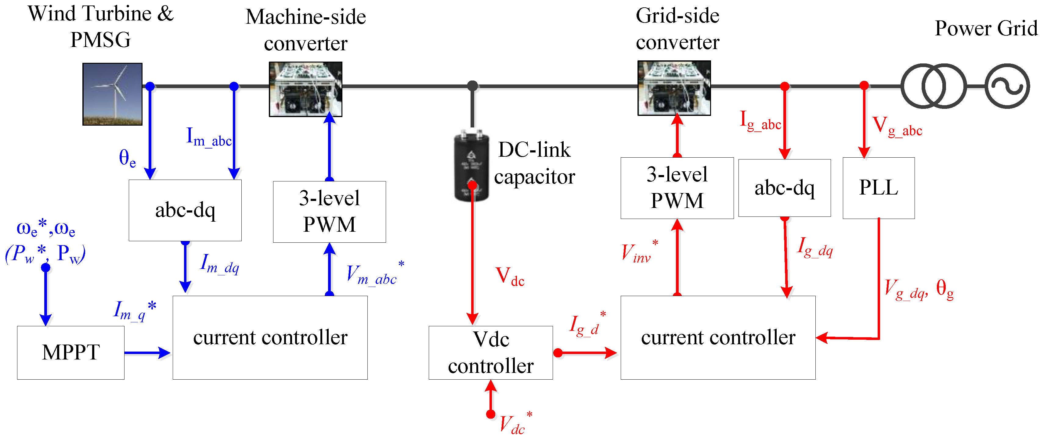
In this paper, a PMSG based wind power system with a full-scale back-to-back converter is modeled as shown in
Figure 1. Generally, the maximum power from the wind can be derived as:
where ρ is the air density;
r is the radius of the wind turbine blade;
vw is the velocity of wind;
Cp.max is the maximum value of the wind turbine power coefficient; λ
opt is the optimum tip speed ratio; ω
t is the rotational speed of the wind turbine rotor [
3].
As shown in Equations (1)–(3), the maximum wind turbine generation power can be extracted at the maximum point of the wind turbine power coefficient. To extract the maximum generation power, the rotational speed of the wind turbine should be controlled to equal the optimum rotational speed of the wind turbine set by the machine-side converter (MSC). In this paper, the maximum value of the power coefficient
Cp,max is set to 0.4412 at the optimum value of the tip speed ratio λ
opt is 7.206 [
3].
As illustrated in
Figure 1, the wind turbine is integrated to the grid through a full-scale back-to-back converter that consists of the MSC and the grid-side converter (GSC). Usually, the converter controllers are based on the synchronous dq reference frame. To deal with unbalanced faults, the GSC need to utilize the decoupled double synchronous reference frame (DDSRF) phase-locked loop (PLL) and current controller that can separate and detect the positive-, negative-sequence component [
2,
5].
Figure 1.
Configuration of a wind power system and control block diagram.
Figure 1.
Configuration of a wind power system and control block diagram.
2.2. Dynamic Braking Resistor
A dynamic braking resistor (DBR) is applied to protect the over-voltage of the DC-link capacitor in the full-scale converters. During grid faults, the GSC of the wind power system suffers difficulties to exactly control power injection to the grid because the grid voltage is easily distorted. If the MSC cannot figure out the fault condition, it may deliver the maximum power from the turbines to the GSC. The instant power mismatch between the MSC and the GSC leads to overvoltage in the DC-link that can have detrimental effects on the system. Therefore, the DBR circuit operates to consume excessive accumulated energy in the DC-link capacitor.
Figure 2 shows the DBR circuit and its controller. When the voltage at the PCC drops under 0.8 p.u, the DBR circuit will operate [
10].
Figure 2.
Configuration of a dynamic braking resistor.
Figure 2.
Configuration of a dynamic braking resistor.
3. Voltage Measurement Method
3.1. Conventional Method
The fundamental component method is presented in IEC 61400-21, which offers the power measurement requirements of a wind power system [
6,
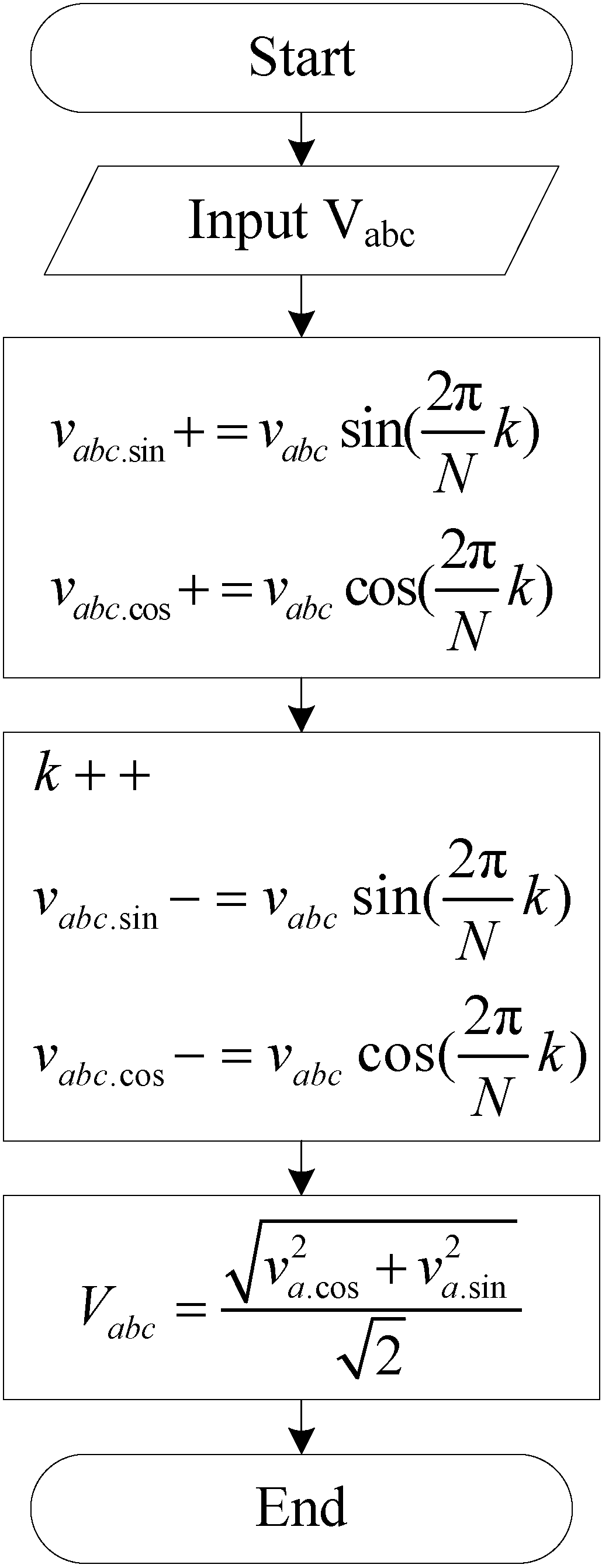
7]. This paper selects this method as a conventional method to compare the performance of the proposed one. This method can measure the fundamental frequency component of the grid voltage phasor using the Fourier transform as
where
T is the period of the grid voltage; ω
1 is the angular speed of the fundamental frequency of the grid voltage;
Va1.cos and
Va1.sin are the fundamental components of the grid voltage. Equation (4) can be represented by the discrete Fourier transform as:
Assume that the phase voltage
va is sampled
N times per cycle of the voltage waveform. Then, the RMS of grid voltage (
Va1) can obtained as:
Figure 3 shows the flowchart of the conventional algorithm implemented in the DLL block of PSIM software using C-code programming. To reduce the computational burden to calculate the fundamental components using Equation (5), a successive window that updates the oldest one with the latest one using a ring-type buffer has been used [
11].
Figure 3.
Flowchart of the conventional algorithm.
Figure 3.
Flowchart of the conventional algorithm.
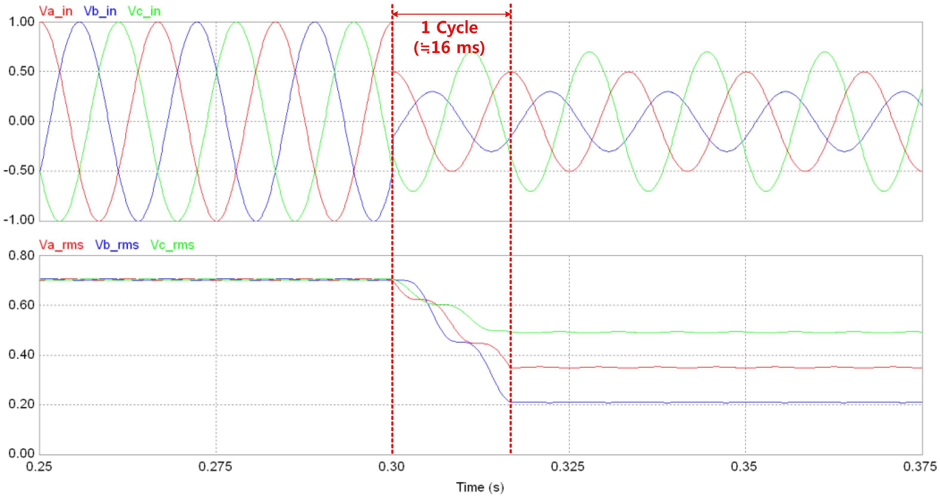
Figure 4 shows the simulation results using the PSIM simulation tool. The first graph in
Figure 4 shows the three-phase grid voltage and the second graph shows the RMS value of the fundamental component of the voltage. At 0.3 s, an unbalanced grid fault occurs with voltage reduction of phase a, b, and c of 50%, 70% and 30%, respectively. According to the conventional method, the RMS value can be calculated accurately, but there is time delay of about 16 ms in the transient period.
Figure 4.
Simulation results of the conventional method: the grid voltage (top) and the measured RMS value of the fundamental component (bottom).
Figure 4.
Simulation results of the conventional method: the grid voltage (top) and the measured RMS value of the fundamental component (bottom).
3.2. Proposed Voltage Measurement Algorithm
The proposed algorithm is based on on-line parameter estimation [
11].
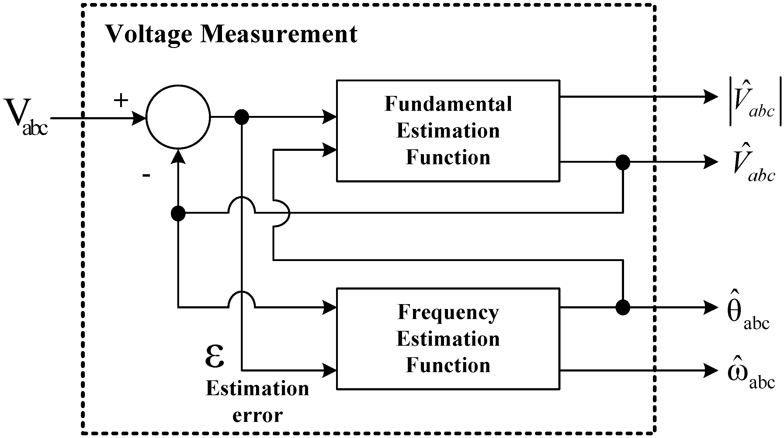
Figure 5 illustrates the simplified block diagram of the proposed voltage measurement algorithm. As shown in
Figure 5, the proposed algorithm is composed of two sub-modules: the first one is to estimate the fundamental component of the grid voltage and the second one is to measure the system frequency and the phase angle.
Figure 5.
Block diagram of the proposed voltage measurement algorithm.
Figure 5.
Block diagram of the proposed voltage measurement algorithm.
3.2.1. Fundamental Component Estimation
For the measurement of the voltage magnitude, this paper proposes to use an adaptive parameter estimation algorithm that can effectively detect variations in the fundamental voltages from the measured phase voltages [
12,
13]. This method can be mathematically derived by a strictly positive real (SPR) Lyapunov method as follows [
14]:
Consider the following plant:
where
y(
t) is the output,
u(
t) is the input, and θ
* is the parameter to be estimated. Then, if we assume θ(
t) as the estimate of θ
*, the estimated output
can be obtained as:
Then, the estimation error, which represents the estimation accuracy of algorithm, can be defined as
For minimizing the cost criteria of
ε with respect to θ, we can define the objective function
J(θ) as:
The optimal point of the objective function can be obtained using the gradient method with respect to θ as:
where
k is the adaptive gain which is positive (
k > 0).
In this paper, the plant of Equation (7) would be the grid voltage. The actual grid voltage,
v(
t), can be decomposed into DC component, fundamental component and harmonics as:
where
Vk, ω
k and φ
k represent the magnitude, angular frequency, and phase angle of the
kth harmonic component;
Vk1 = cos
φk and
Vk2 = sin
φk. Equation (11) can be represented in the form of Equation (7) as:
where
,
.
Assume that the fundamental frequency ω
1 is already known, ϕ in Equation (13) is also a known parameter. Then, θ in Equation (13) is the parameter to be estimated. According to above equations, the objective function of the proposed algorithm can be defined as follows:
To find the update law with respect to θ, the gradient method is applied to the objective function. Then, the update law can be derived as:
The adaptive update law for estimation of each individual component in
is obtained as:
Finally, we can calculate the magnitude of the fundamental component of the phase voltage as:
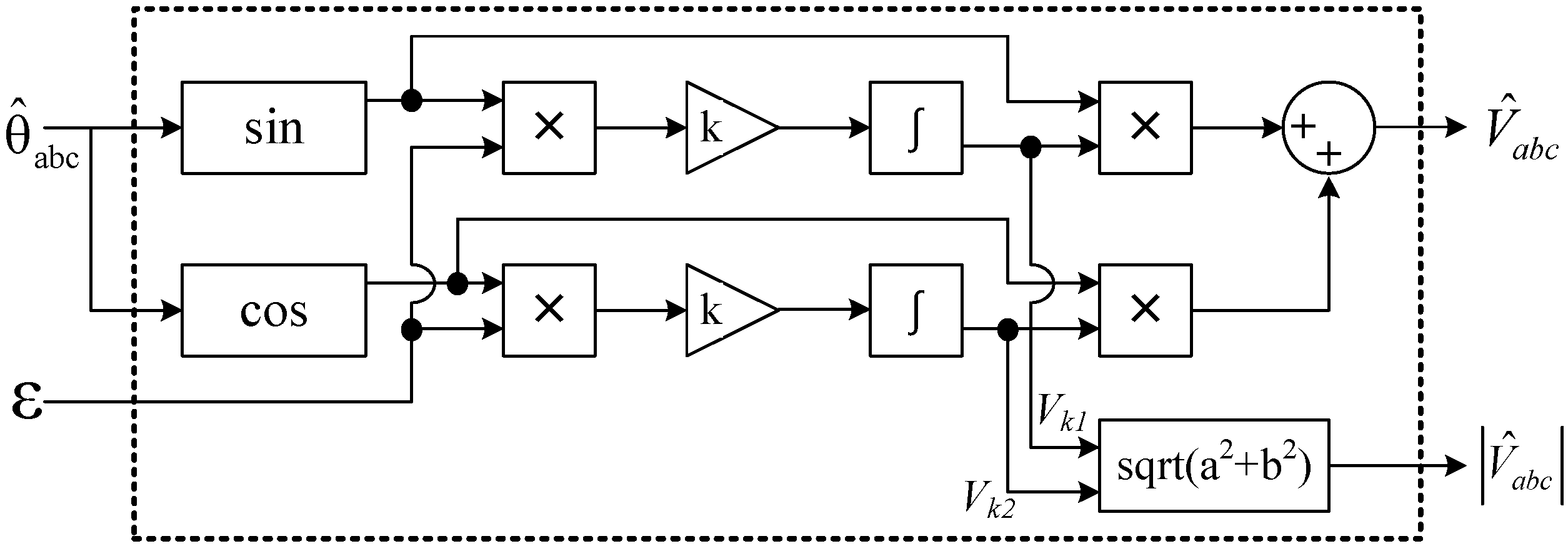
From Equation (16), the block diagram of the fundamental estimation function can be illustrated as
Figure 6. The adaptive gain k is set to 500.
Figure 6.
Block diagram of the fundamental estimation function.
Figure 6.
Block diagram of the fundamental estimation function.
3.2.2. System Frequency Estimation
The system frequency, ω
1, should be updated for accurate estimation of the fundamental voltage component. Adaptive parameter estimation method can be applied to the frequency estimation function and the update law of the fundamental frequency can also be developed by gradient method as:
where α is an adaptive gain of frequency estimation function, which is a positive number. The frequency estimation is represented in
Figure 7.
Figure 7.
Block diagram of the frequency estimation function.
Figure 7.
Block diagram of the frequency estimation function.
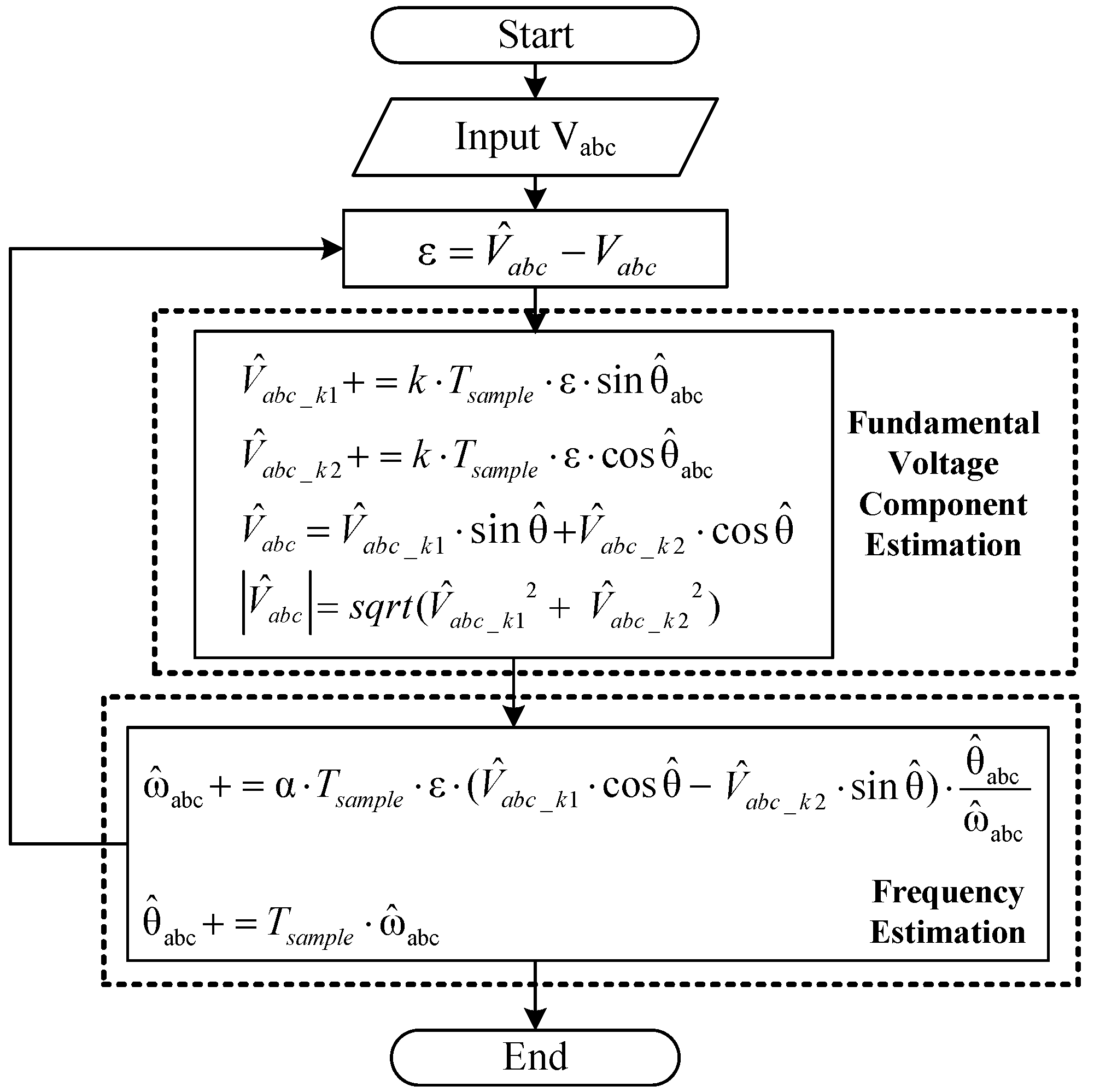
The performance of the proposed voltage measurement method is examined by PSIM simulation.
Figure 8 shows the flowchart of the estimation algorithm.
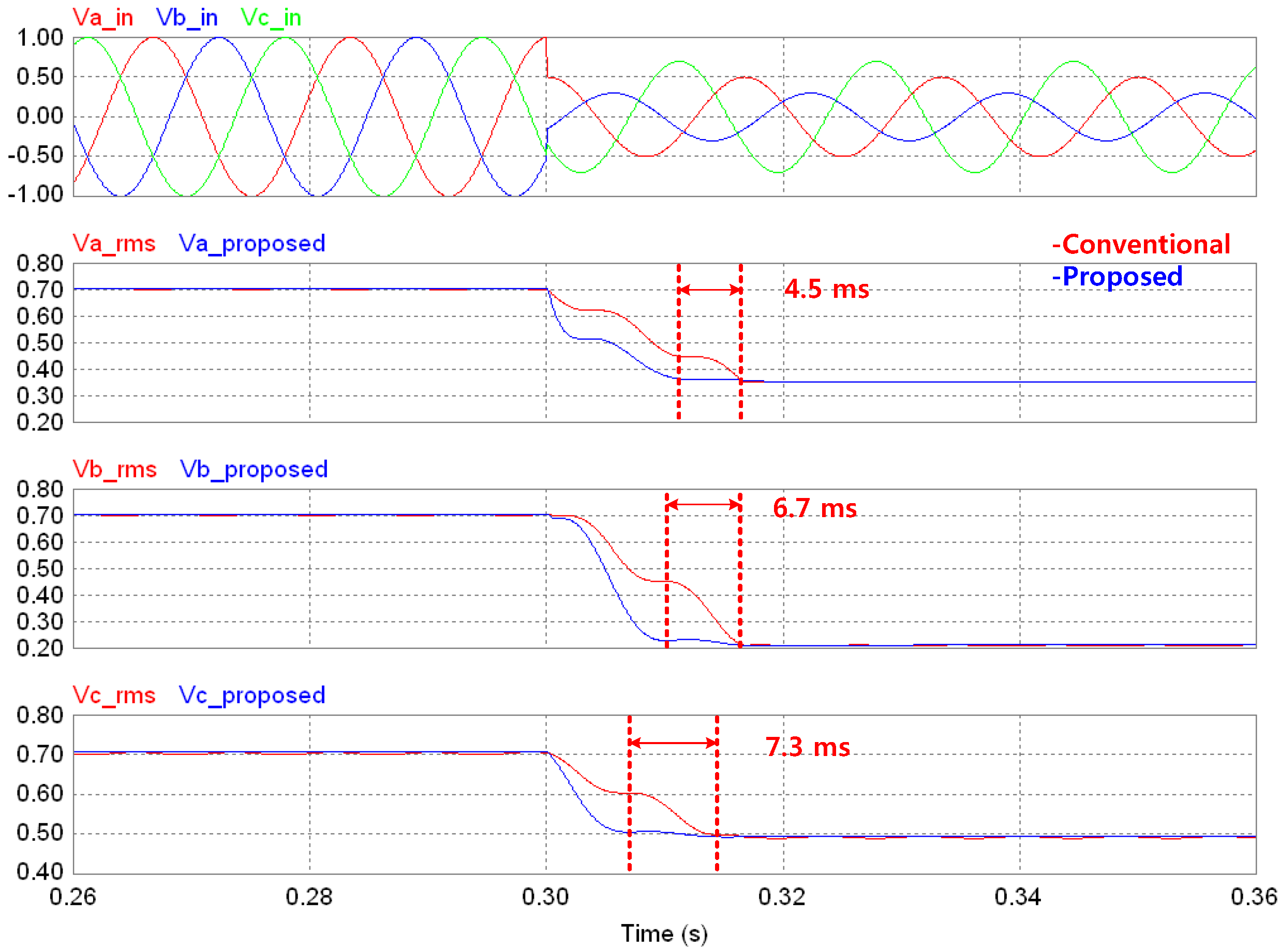
Figure 9 shows the simulation results comparing the performance proposed method to the conventional one. The first graph in
Figure 9 shows the three-phase grid voltage and the remaining graphs represent the measured RMS values of each phase voltage using the conventional and proposed methods. When an unbalanced fault occurs at 0.3 s, the proposed method reaches the solution in less than one cycle. It should be noted that the proposed method can detect the fault condition at least 4.5 ms faster than the conventional one.
Figure 8.
Flowchart of proposed algorithm.
Figure 8.
Flowchart of proposed algorithm.
Figure 9.
Simulation results of proposed method.
Figure 9.
Simulation results of proposed method.
4. Simulation Studies
The voltage measurement methods are applied to a PMSG-type wind power system. The wind power system and voltage measurement algorithms have been implemented using MATLAB/Simulink. The wind power system consists of a wind turbine, a machine-side converter (MSC), a dynamic braking resistor (DBR), and a grid-side converter. The converters are implemented using power electronics switches. The specifications of the wind power systems are listed in
Table 1.
In the normal condition, the wind power system operates in the maximum power point tracking (MPPT) mode. The rotational speed of the PMSG is controlled by the MSC to extract the maximum power while the GSC controls the DC-Link voltage and the reactive power output. When the RMS value of the grid voltage drops below 0.8 p.u or the DC-link voltage exceeds 6.5 kV, the DBR will be enabled to exhaust the accumulated energy of the link capacitor.
Table 1.
Simulation parameters.
Table 1.
Simulation parameters.
| Wind Turbine |
| Blade radius | r | 83.5 m |
| Air density | ρ | 1.225 kg/m3 |
| Rated wind speed | Vw_rated | 10 m/s |
| PMSG |
| Rated power | Pm | 7.35 MW |
| Stator phase resistance | Rs | 8.67 mΩ |
| d-axis inductance | Ld | 2.86 mH |
| q-axis inductance | Lq | 3.44 mH |
| Number of pole pairs | Npp | 18 |
| Power Converter Spec. |
| Line-to-line voltage(at PCC) | VPCC | 3.3 kV |
| Line freq. | fgrid | 60 Hz |
| Switching freq. | fsw | 14 kHz |
| Rated DC-link voltage | Vdc_link | 5400 V |
| Link capacitance | C | 16 mF |
| Resistance of DBR | RDB | 10 Ω |
To validate the proposed voltage measurement algorithm, two case studies are conducted in this section. The first case shows the voltage measurement performance during the balanced grid fault. In the second case, the unbalanced grid fault condition is simulated.
4.1. Case 1: Balanced Fault
Case 1 simulates wind power system operation during a balanced fault.
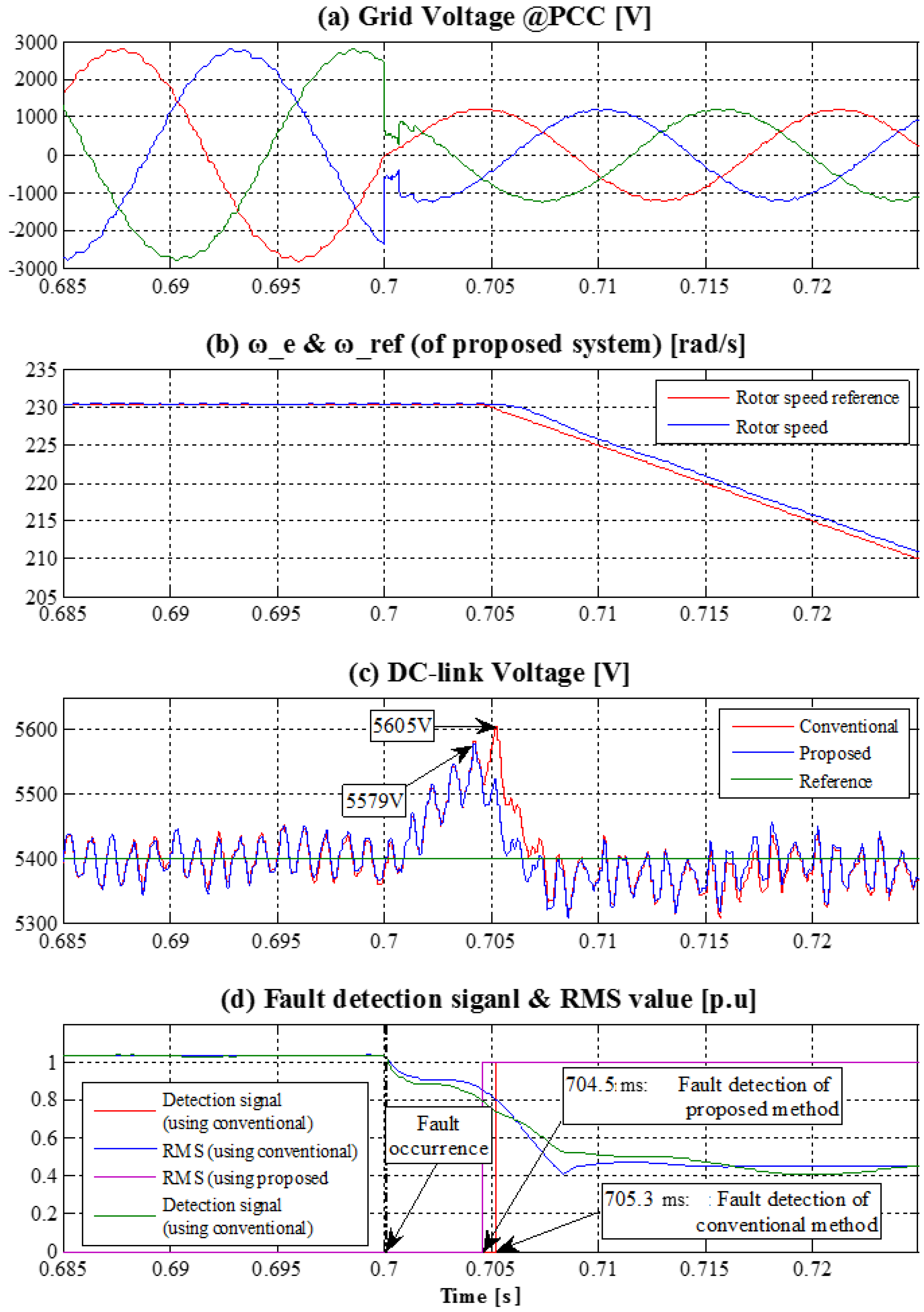
Figure 10 shows the simulation results of this case. Before the fault condition, the wind power system generates 6 MW constant power and the voltage measurement algorithm measures an accurate RMS value. When the balanced grid fault occurs at 0.7 s, the three-phase grid voltage simultaneously drops about 50%.
Figure 10a shows the grid voltage at the point of common coupling (PCC). The rotational speed and reference of the PMSG is shown in
Figure 10b. The DC-link voltage is presented in
Figure 10c.
Figure 10d shows the voltage measurement performance of proposed algorithm compared to the conventional one.
During the fault, the GSC of the wind power system suffers difficulty to supply active power to the grid when the grid voltage drops severely. Then, the power unbalance between the power generated by the turbine and the power injected to the grid causes a significant voltage increase in the DC-link. The control scheme for the wind power system to prevent overvoltage in the DC-link is established as follows: (1) the MSC of the wind power system decreases the tip speed ratio of the wind turbine. The amount of tip speed reduction is determined according to the energy missing at the PCC due to the grid voltage drop caused by the MSC controller. In addition; (2) if the grid voltage drops under 0.8 p.u., the dynamic breaking resistor (DBR) starts operation to prevent excessive overvoltage of DC-link. This means that the surplus energy will be burnt out in the DBR. Therefore, fast fault detection can help to reduce the size of DBR and cooling system. In this simulation, the pitch angle control scheme of the wind turbine blades has not been applied because the pitch angle control has a slow response compared to power converter control.
Figure 10c shows the DC-link voltage increase when we use either the conventional or the proposed method. The rotational speed of wind turbine is reduced according the optimal TSR as shown in
Figure 10b. As seen in
Figure 10d, the fault detection time of the conventional method is 5.3 ms but the proposed measurement method detects the grid fault faster, within 4.5 ms after the fault. As a result, the DC link voltage increase can be reduced from 5605 V to 5579 V when we use the proposed method as shown in
Figure 10c.
Figure 10.
Simulation results of Case 1: (a) grid voltage waveforms; (b) the rotor speed of the PMSG; (c) DC-link voltage of the full-scale inverter; and (d) fault detection according to the measure RMS voltage.
Figure 10.
Simulation results of Case 1: (a) grid voltage waveforms; (b) the rotor speed of the PMSG; (c) DC-link voltage of the full-scale inverter; and (d) fault detection according to the measure RMS voltage.
4.2. Case 2: Unbalanced Fault
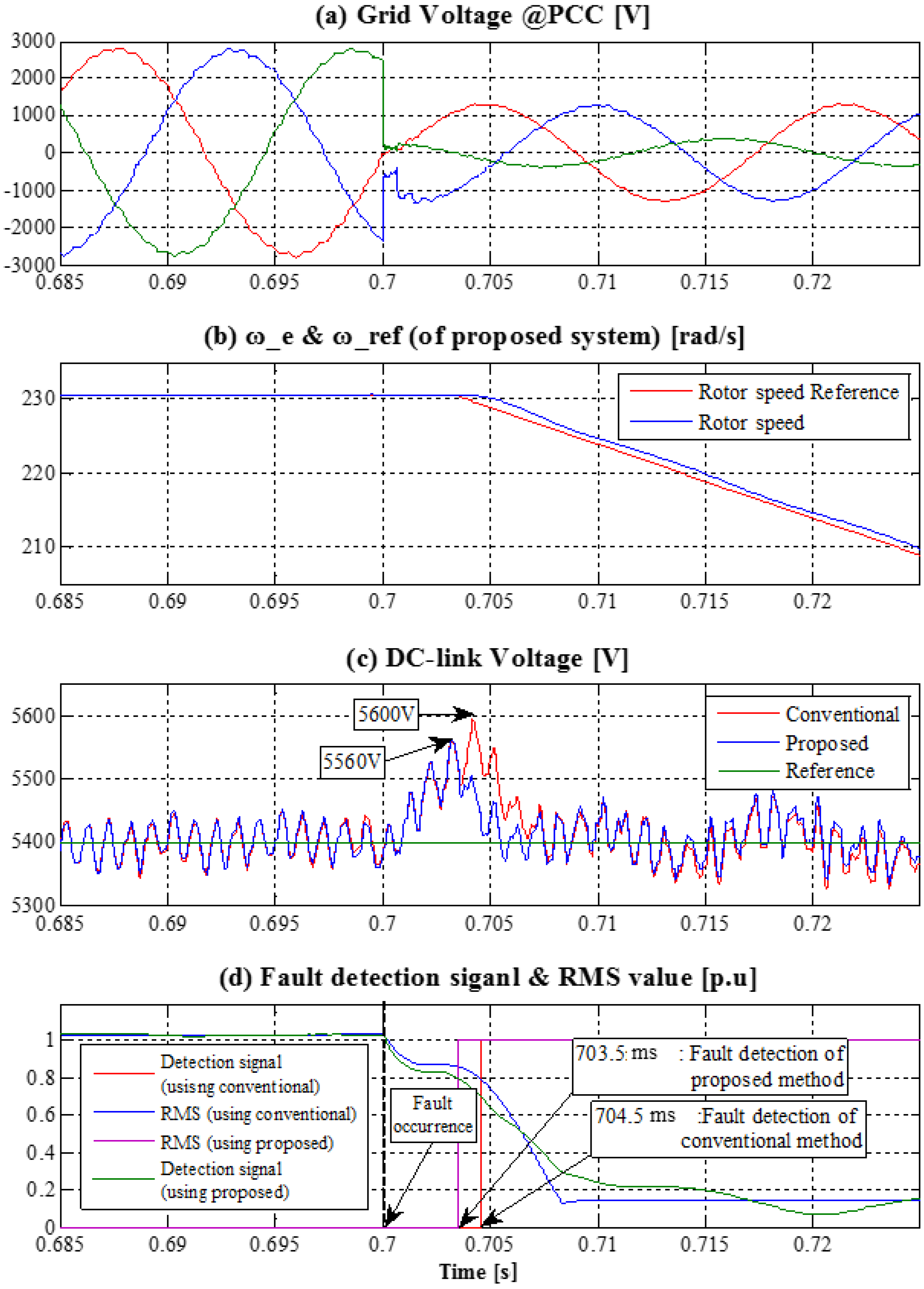
In Case 2, it is assumed that the unbalanced fault occurs in the grid voltage. The magnitude of phase C voltage reduces 80% more than other phases.
Figure 11 shows the simulation results of Case 2. In
Figure 11, the unbalanced grid fault occurs at 0.7 s. In this case, the proposed method can detect the grid fault in 3.5 ms whereas the conventional method takes 4.5 ms, as shown in
Figure 11d. It is noted that that the proposed method reduces the DC-link voltage rise to 5.56 kV compared to 5.60 kV of the conventional method as shown in
Figure 11c. This is because the proposed method can detect the grid fault quickly and prevent the over-voltage of DC-link capacitor reliably in any fault situation.
Figure 11.
Simulation results of Case 2: (a) grid voltage waveforms; (b) the rotor speed of the PMSG; (c) DC-link voltage of the full-scale inverter; and (d) fault detection according to the measure RMS voltage.
Figure 11.
Simulation results of Case 2: (a) grid voltage waveforms; (b) the rotor speed of the PMSG; (c) DC-link voltage of the full-scale inverter; and (d) fault detection according to the measure RMS voltage.
5. Conclusions
Conventionally, the fundamental component method has been used to measure the fundamental voltage and also to detect fault conditions in wind power systems. However, this method takes more than one cycle to accurately measure the voltage magnitude after a fault occurs. In addition, the detection performance of the conventional method can be degraded when the system frequency fluctuates. For the rapid and accurate fault detection performance, this paper proposes an adaptive parameter estimation algorithm which is based on the adaptive filter theory.
The proposed algorithm can measure multiple parameters of the fundamental voltage component such as the magnitude, frequency, and phase angle. The advantage of the proposed algorithm is that its fault detection speed is faster than that of the conventional method and it is more robust to voltage distortion such as harmonics and frequency variations. Thus, the rapid fault detection method can help restrict the DC-link overvoltage. This means the size of the dynamic breaking resister can be reduced to burn out the accumulated capacitor energy which is proportional to the square of the DC voltage magnitude. In addition, fast detection of fault condition can help the grid-side converter to effectively control the reactive current injection to the grid for fault recovery, which is defined in many LVRT requirements. To validate the proposed method, the proposed algorithm has been tested via c-code programming environment test using PSIM and switching-level power converter simulation in Matlab/Simulink.
Acknowledgments
This research was supported by the Ministry of Science, ICT and Future Planning, Korea, under the Information Technology Research Center support program (NIPA-2014-H0301-14-1005) supervised by the National IT Industry Promotion Agency and by the New & Renewable Energy of the Korea Institute of Energy Technology Evaluation & Planning (KETEP) grant funded by the Ministry of Trade, Industry and Energy (No. 2012T100100064).
Author Contributions
All co-authors have made important contributions to the conception and design of this paper, as well as to the acquisition, analysis or interpretation of data. The review task for data collection has been thoroughly and especially carried out by Cheol-Hee Yoo and Il-Yop Chung. Hyun-Jae Yoo and Sung-Soo Hong have provided practical issues such as controller implementation in power inverters. All of the co-authors have been also involved in drafting and revising the manuscript, so that everyone has given final approval of the current version to be published in Energies.
Conflicts of Interest
The author declares no conflict of interest.
References
- Tsili, M.A.; Papathanassiou, S.A. A review of grid code technical requirements for wind farms. IET Renew. Power Gener. 2009, 3, 308–332. [Google Scholar] [CrossRef]
- Teodorescu, R.; Liserre, M.; Rodriguez, P. Grid Converters for Photovoltaic and Wind Power Systems; John Wiley & Sons: Chichester, UK, 2011. [Google Scholar]
- Ackermann, T. Wind Power in Power Systems; John Wiley & Sons: Chichester, UK, 2005. [Google Scholar]
- Yazdani, A.; Iravani, R. Voltage-Sourced Converters in Power Systems; John Wiley & Sons: Chichester, UK, 2010. [Google Scholar]
- Blaabjerg, F.; Teodorescu, R.; Liserre, M.; Timbus, A.V. Overview of control and grid synchronization for distributed power generation systems. IEEE Trans. Ind. Electron. 2006, 53, 1398–1409. [Google Scholar] [CrossRef]
- IEC International Standard. In Wind Turbines—Part 21: Measurement and Assessment of Power Quality Characteristics of Grid Connected wind Turbines. IEC 61400–21, Edition 2.0; IEC: London, UK, August 2008.
- Niiranen, J. About the active and reactive power measurements in unsymmetrical voltage dip ride-through testing. Wind Energy 2008, 11, 121–131. [Google Scholar] [CrossRef]
- Qi, L.; Qian, L.; Cartes, D.; Woodruff, S. Initial results in prony analysis for harmonic selective active filters. In Proceedings of the IEEE Power Engineering Society General Meeting, Montreal, QC, Canada, 18–22 June 2006.
- Alrawashdeh, H. An Adaptive Kalman Filter for Voltage Sag Detection in Power Systems. Ph.D. Dissertation, Western Michigan University, Kalamazoo, MI, USA, 2014. [Google Scholar]
- Uehara, A.; Pratap, A.; Goya, T.; Senjyu, T.; Yona, A.; Urasaki, N. A coordinated control method to smooth wind power fluctuations of a PMSG-Based WECS. IEEE Trans. Energy Convers. 2011, 26, 550–558. [Google Scholar] [CrossRef]
- Phadke, A.G.; Thorp, J.S.; Adamiak, M.G. A new measurement technique for tracking voltage phasors, local system frequency, and rate of change of frequency. IEEE Trans. Power App. Syst. 1983, PAS-102, 1025–1038. [Google Scholar] [CrossRef]
- Qian, L.; Cartes, D.; Li, H. An improved adaptive detection method for power quality improvement. IEEE Trans. Ind. Appl. 2008, 44, 525–533. [Google Scholar] [CrossRef]
- Kang, H.; Yoo, C.; Chung, I.; Won, D.; Moon, S. Intelligent coordination method of multiple distributed resources for harmonic current compensation in a microgrid. J. Electr. Eng. Technol. 2012, 7, 834–844. [Google Scholar] [CrossRef]
- Ioannou, P.A.; Sun, J. Robust Adaptive Control; Prentice Hall: Upper Saddle River, NJ, USA, 1996. [Google Scholar]
© 2014 by the authors; licensee MDPI, Basel, Switzerland. This article is an open access article distributed under the terms and conditions of the Creative Commons Attribution license (http://creativecommons.org/licenses/by/4.0/).


