Development and Improvement of an Intelligent Cable Monitoring System for Underground Distribution Networks Using Distributed Temperature Sensing

Abstract
: With power systems switching to smart grids, real-time and on-line monitoring technologies for underground distribution power cables have become a priority. Most distribution components have been developed with self-diagnostic sensors to realize self-healing, one of the smart grid functions in a distribution network. Nonetheless, implementing a real-time and on-line monitoring system for underground distribution cables has been difficult because of high cost and low sensitivity. Nowadays, optical fiber composite power cables (OFCPCs) are being considered for communication and power delivery to cope with the increasing communication load in a distribution network. Therefore, the application of distributed temperature sensing (DTS) technology on OFCPCs used as underground distribution lines is studied for the real-time and on-line monitoring of the underground distribution power cables. Faults can be reduced and operating ampacity of the underground distribution system can be increased. This paper presents the development and improvement of an intelligent cable monitoring system for the underground distribution power system, using DTS technology and OFCPCs as the underground distribution lines in the field.1. Introduction
With the application of the Smart Grid concept to the power system to optimize energy efficiency, technologies for efficient system operation and real-time, on-line monitoring are being developed in the distribution system. Currently, no real-time, on-line monitoring is being carried out on cables, which account for a high percentage of faults in underground distribution systems. In addition, distribution lines are continually being extended or newly installed to address the ever-increasing demand for power by applying comprehensive base ampacity to the operation of the system; however, problems related to the securing of installation sites have been increasing.
Smart grid application requires first, the establishment of electrical power system communication networks. Presently, for underground distribution systems, electrical power networks and communication networks operate separately. In the case of the optical fiber composite power cable (OFCPC), which is a power cable embedded with optical cables, electrical power networks and communication networks can be established simultaneously. Distributed temperature sensing (DTS) technology to measure the temperatures of the optical cables can be applied as well.
If the DTS technology is applied to underground distribution power cables, which currently account for most of the faults in underground distribution systems, the underground distribution power cables can be monitored in real-time and on-line. Moreover, if the temperatures of the underground distribution power cables can be measured in real-time, the real-time and dynamic ampacities of the cables can be determined based on the real-time measurements of the temperatures. With regard to the distribution systems operated with uniform standard ampacity below the allowed ampacity for stable system operation, if their operating and dynamic ampacities can be identified in real-time and applied to the operation of these distribution systems, the operating ampacity of the distribution line may be increased greatly, unlike maintaining an acceptable safety margin.
An intelligent cable monitoring system applying DTS technology to OFCPCs has been developed to construct communication networks and to monitor underground distribution power cables in real-time and on-line. Likewise, a test-bed of the intelligent cable monitoring system has already been established, considering the diverse operating environments of underground power distribution systems. Diverse field tests have been carried out to improve the system. This paper presents the improvement and test results of the intelligent cable monitoring system, which is to be applied to underground distribution lines in the field.
2. Design of the Intelligent Cable Monitoring System
2.1. Overview of DTS
If the actual temperature of the installed underground distribution power cable can be monitored in real-time, actual ampacity can be derived in relation to the allowable cable temperature and be used to operate the underground distribution system more effectively. At the same time, many underground distribution line faults can be corrected by on-line monitoring the cable itself. For real-time checking of cable temperature, DTS, which is the technology used to check the optical cable temperature in an underground distribution system, has been considered.
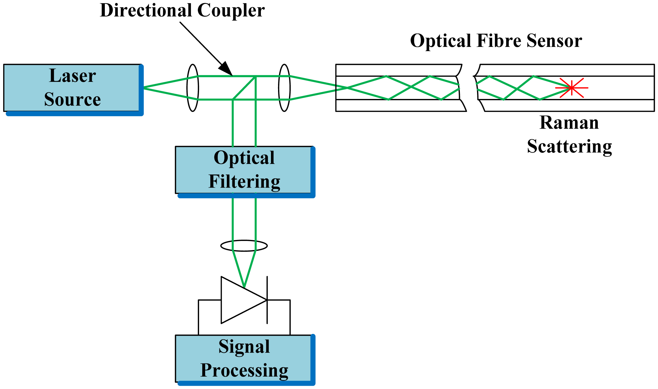
As shown in Figure 1, in the DTS, distance is measured by analyzing the return time of the scattered light after the insertion of the laser source into the optical cable and by analyzing the back-scattered lights; Raman scattered light carrying the temperature characteristics is filtered and analyzed to obtain the optical cable temperature [1].
2.2. Configuration of the Intelligent Cable Monitoring System
Normally, the DTS system is used for temperature monitoring and estimation of real-time ratings of transmission cables [1–4]. However, it is not suitable for underground distribution cables because a distribution cable network is more complex than a transmission cable. In particular, an underground distribution network has many branch cables at pad-mounted switchgears. Therefore, the DTS system for transmission cables cannot be used for distribution cable networks directly. Still, with the steady increase in the use of optical communications in power networks, communication costs of utilities have also sharply increased. Therefore, the use of OFCPCs in power networks is increasing [5,6]. If OFCPCs are used, power line communications can be enabled without establishing separate communication networks. Nonetheless, communications will likely be disabled by a fault in the power cables, thus making a fault-preventing monitoring system indispensable.
Unfortunately, underground distribution cables are not monitored in real-time and on-line due to the lack of an economical and accurate monitoring system. As a solution, the intelligent cable monitoring system is established as an economical, accurate, real-time monitoring system for underground cables. It uses optical fiber sensors to detect cable temperatures.
The intelligent cable monitoring systems for OFCPCs used in communication networks should be designed for early fault detection to prevent fault propagation [7]. To use OFCPCs for power transmission and communication in an underground distribution network, it is important to design splice and branch lines to minimize communication faults in the event of a power cable fault. Additionally, the system can economically monitor the entire underground distribution network with its many feeders and branch lines. The monitoring system can also interface with distribution automation systems for effective maintenance and operation. However, the continuous partial discharge (PD) measurement for every cable in the distribution network is very expensive. In this intelligent cable monitoring system, PD sensors can be connected to OFCPC at the optical switch so that distribution network operator can manage the PD measurement site and period.
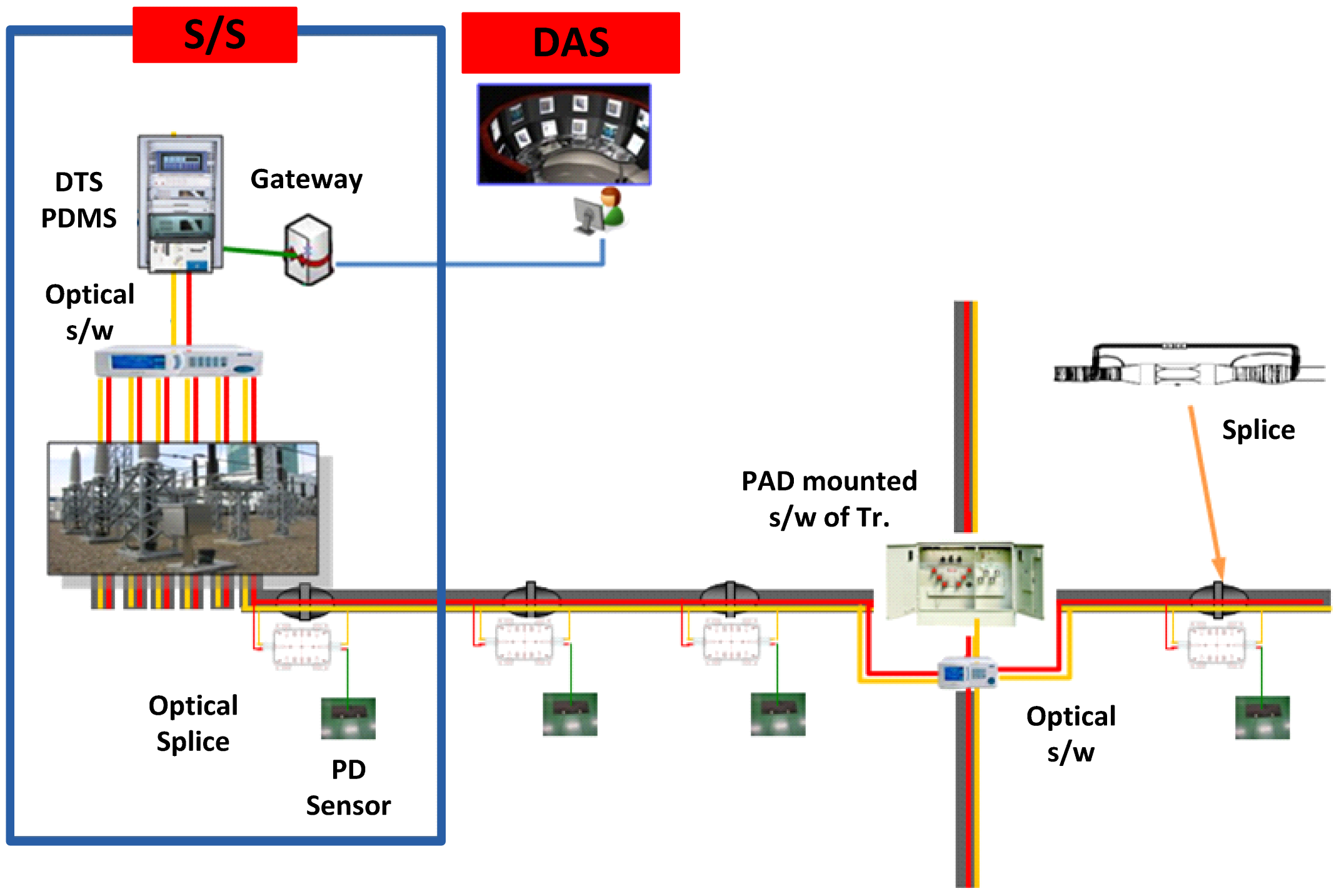
Figure 2 shows the configuration of the intelligent cable monitoring system to be applied to underground distribution lines. A central system is installed at the power distribution center and operated in linkage with the power distribution automation system. This intelligent cable monitoring system consists of OFCPCs for temperature distribution measurement, server for data storage, PC for the operation of the operating program, terminal device for data transmission in linkage with the distribution operating system, route change optical switch to determine the laser injection lines, optical splice in the region of the cables' straight connection material, and mobile PD measuring device. In this system, the route-changing optical switch, remotely controlled by the system's operation program, is used to configure the system economically; it enables the one channel DTS to monitor multiple lines one by one in an underground distribution system with many main and branch lines, which make the simultaneous and real-time monitoring of all lines inefficient and too costly.
The major functions of this monitoring system include the detections of overload temperature, impending cable fault, and accurate fault location. Accurate fault detection and location can prevent the reclosing of the circuit breaker installed in the substation. Moreover, with this system, high-impedance ground faults may be detected more accurately. In addition, it must be able to calculate the real-time rating of cables by conductor temperature estimation.
3. Construction of the Test-Bed
3.1. System Component Installation
3.1.1. OFCPC
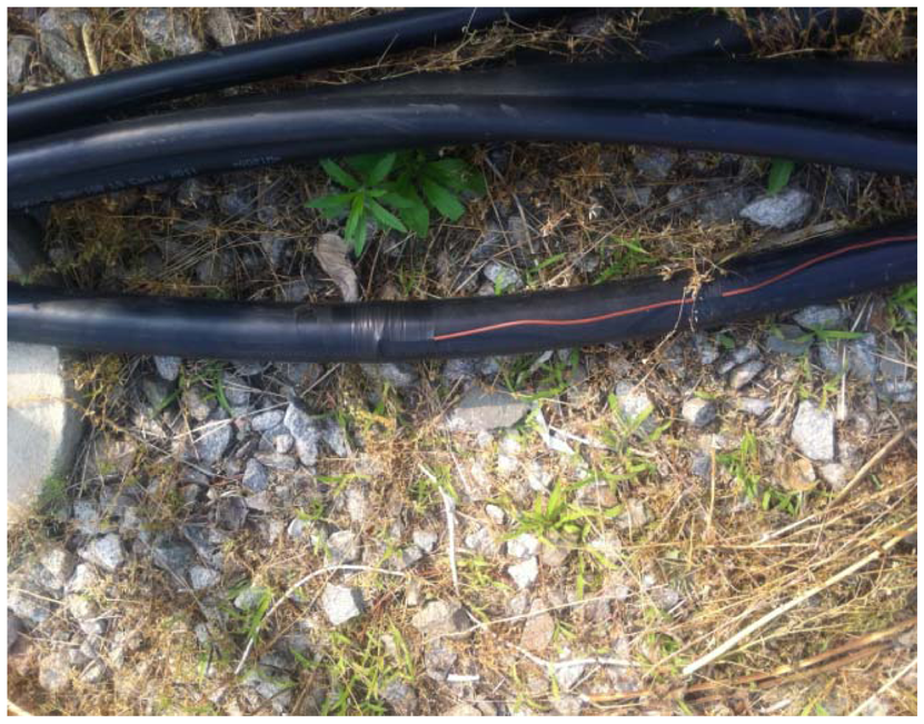
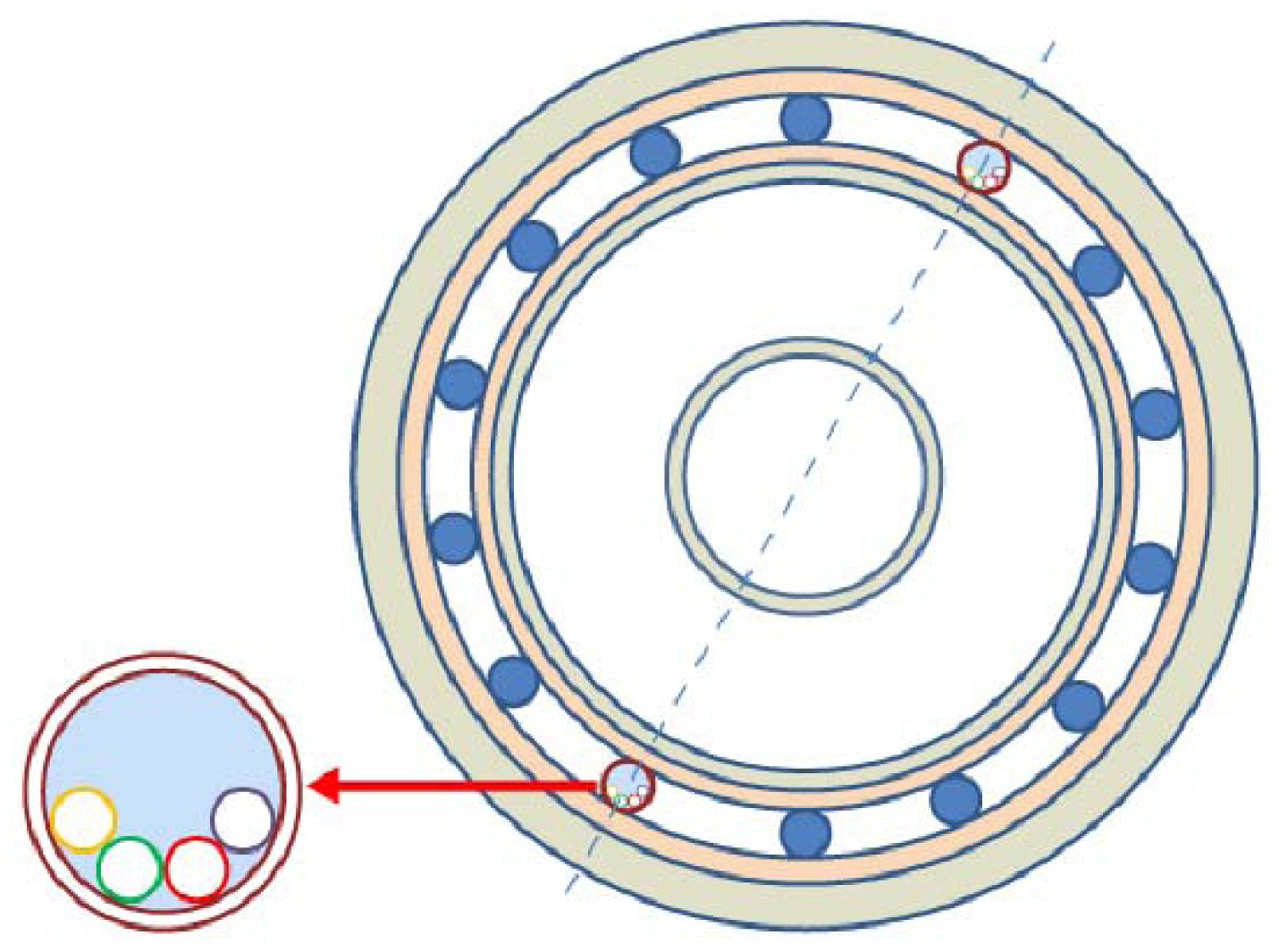
Figure 3 depicts the structure of the optical fiber composite underground distribution power cable used in this study. Four strands of optical fibers are inserted into a stainless steel tube placed between neutral lines. Two different stainless steel tubes are used to prevent communication interruption in case of a cable fault. In this study, optical fibers were inserted into the concentric neutral type tree retardant cross linked polyethylene insulated PVC sheathed water-proof power cable (TR-CNCV-W) 325 mm2, which is the most frequently used cable in power distribution systems. The optical fibers contained in one of the two stainless steel tubes are connected to the DTS system and used for measuring temperature, whereas the other optical fiber is used for the communication network. This cable with the two stainless steel tubes that are additionally inserted, and has essentially the same structure as that of the existing CNCV cable; therefore, the performance of the cable itself remains unchanged.
3.1.2. Cable Joint and Optical Switch
The most important aspect of applying the intelligent cable monitoring system to an on-site underground power distribution system is the on-site applicability of the cable joint of the OFCPC to be laid to replace the underground distribution cable. In other words, the cable joint of the OFCPC should be easy to construct and should be economical for the underground distribution system, where there are many cable connecting sections. Furthermore, it should be able to resolve the issues of optical fiber connection and water-tightness with the cable joint kits of the underground distribution cable directly used for the connection of power cable of the optical composite cable. In addition, the monitoring function of the cable joint kit and the stability of communication cable in case of a fault should be secured at the same time.
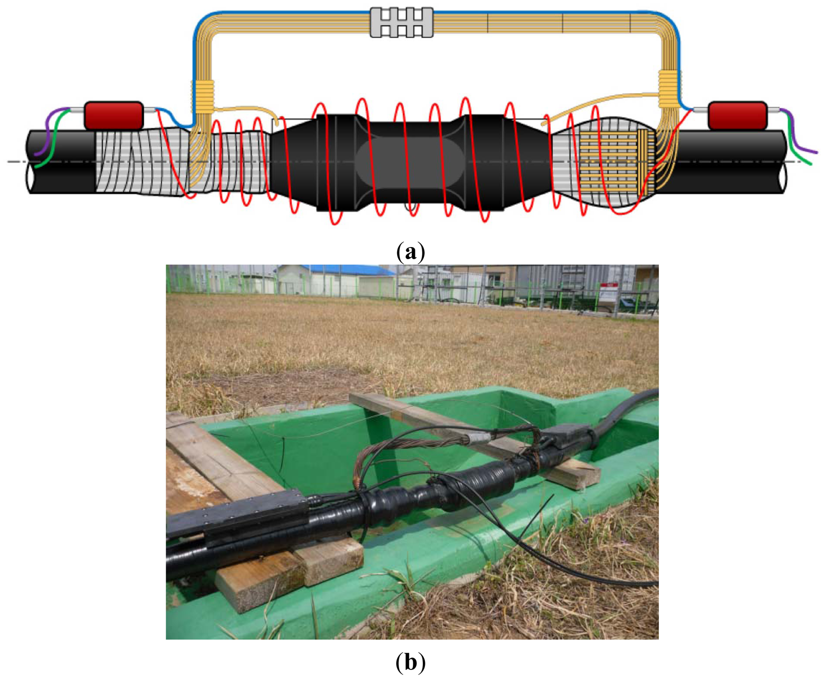
Based on the various reviews that were performed to satisfy the requirements, the cable joint of the intelligent cable monitoring system to be applied on an on-site underground distribution line was designed as shown in Figure 4 and installed on the test-bed. As shown in Figure 4, in the designed OFCPC cable joint, the OFCPCs are connected using the cable joint kit of the existing underground distribution cable as is. Furthermore, the stainless steel tube housing the optical fiber cables of the OFCPC is connected to the optical joint box installed on top of the cable. In the optical joint box, DTS measurement optical cores and communication optical cores among the optical fiber cables in the OFCPC are collected separately and connected to their respective flexible-type optical fiber cables. As shown in Figure 4, the flexible-type optical fiber cable for DTS measurement winds around and monitors the cable joint kit, which has a high fault rate, whereas the flexible-type optical fiber cable for communication is installed along the neutral line to ensure stability in case of a fault of the cable joint kit. These flexible-type optical fiber cables for DTS measurement and communication are connected to the optical fiber cables in the OFCPC in the next optical joint box. Furthermore, it is a very efficient way of using the flexible-type optical fiber cable to prevent optical losses made from bending of cable.
By using the cable joint kit as is, the cable joint of an intelligent cable monitoring system does not have to consider the electric field, etc., and additional constructions such as the cutting of the OFCPC can be minimized. With the present construction approach, the cable joints of existing underground power distribution cables remain unchanged. In addition, since the optical joint box for connecting the optical fiber cables can be installed on top of the power cables, installation space can be secured in the present construction environment. Furthermore, since the water-tight treatment of the cable joint kit is the same as that of the existing cable joint kit, the cable joint kit of the intelligent cable monitoring system can be constructed easily, and its water-proof characteristics can be secured. For reference, the optical joint box of the cable joint can be used, as is, as a termination joint of the underground distribution cable and as an elbow connector of the OFCPC in a pad-mounted switch or transformer.
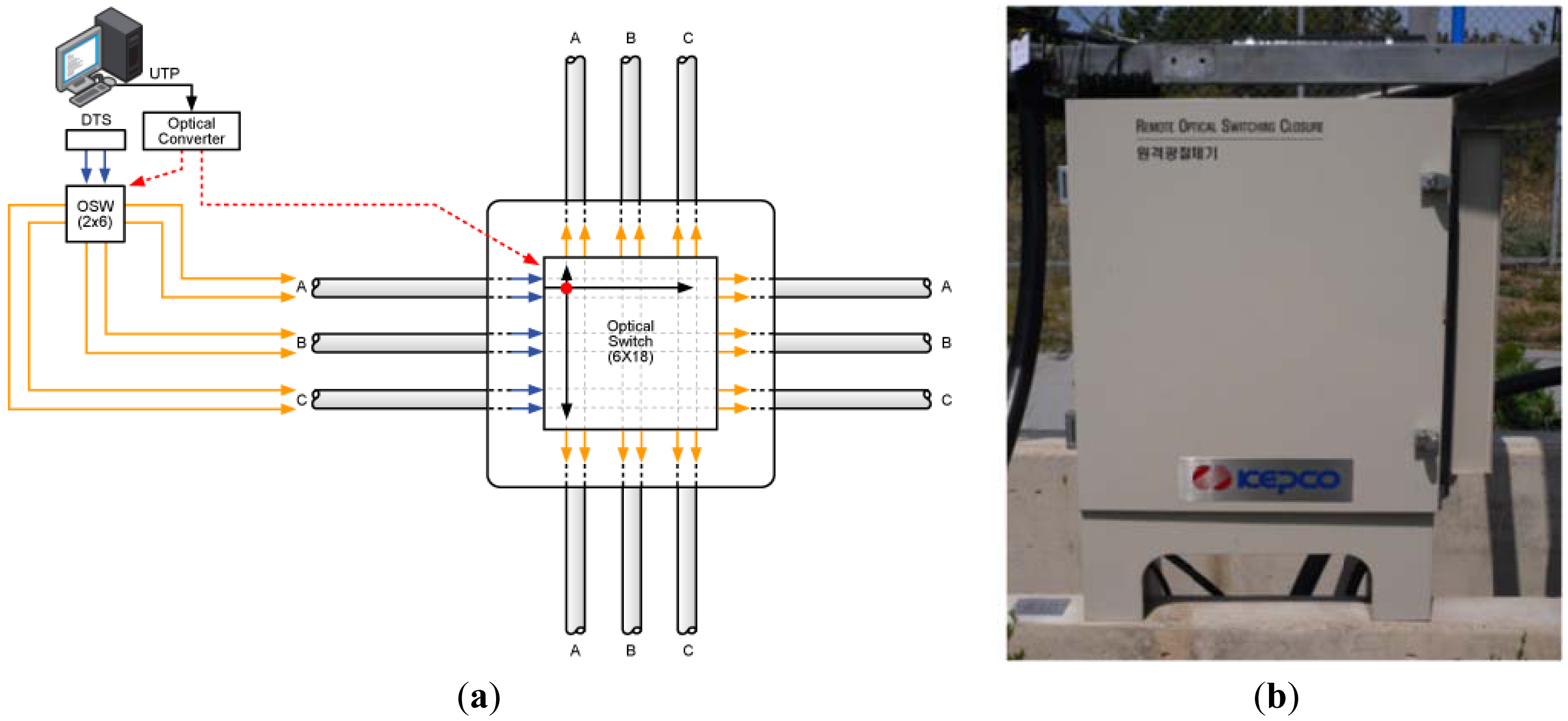
On the other hand, since the underground distribution system has many branch lines, the monitoring system needs to be constructed efficiently and economically. This means that the branch lines should be monitored with a minimum number of DTS channels. For this, an optical switch that can be installed on the pad-mounted switch or transformer was designed in this study, as shown in Figure 5. In distribution power system, one main distribution line can be divided into maximum three branch lines. Therefore, one DTS channel through the main line can be connected to optical paths of three branch lines sequentially. The optical switch, as shown Figure 5, can change the optical paths for monitoring cable temperature at points where the underground distribution lines branch.
3.1.3. Operation Program
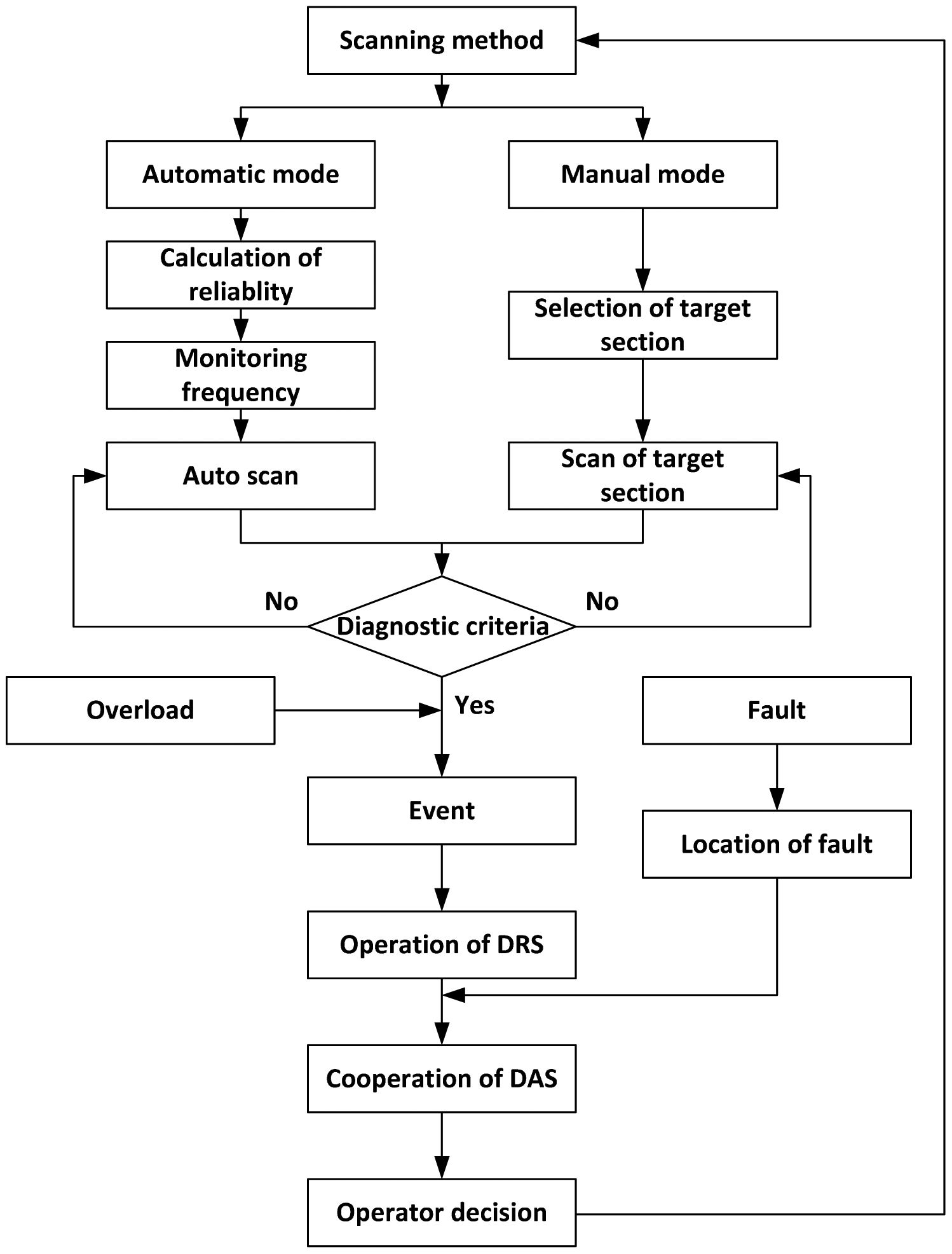
Because of the many main and branch cables in an underground distribution system, it is difficult to prevent faults effectively with a simple, sequential monitoring method. Accordingly, an operation program suitable for power distribution cable is proposed in this study, as in Figure 6. The system operator may set the scanning method of the target line to either automatic or manual mode; in automatic mode, the monitoring frequency is automatically set based on the calculated reliability of each section of the underground line, taking into account the fault history and the installation year of the underground line.
Thereafter, the designated section of each line is automatically monitored sequentially. If a situation occurs, where parameters such as temperature or load current have deviated from diagnostic criteria, an event signal is generated and real-time information on the operation condition of the line in question is displayed on the user screen in the distribution automation system of the distribution center. Thereafter, if the alarm situation is cancelled following confirmation by the operator, the system will return to the initial status.
In manual mode, the operator directly designates the section of the target line for monitoring. During monitoring, if a situation occurs outside exceeding diagnostic criteria, an event signal is generated, the situation of the section in question is displayed on the user screen of the distribution automation system and the system will return to the initial status after the operator deals with the situation that triggered the alarm. If the load current of a certain underground line in the distribution automation system increases rapidly to an overload, an event signal is generated, and the actual allowable ampacity of that particular line is displayed on the user screen in the distribution automation system; then, the DTS stops the ongoing monitoring of lines, measures the temperature distribution of the line, and runs the program that calculates the real-time allowable ampacity. If a fault of an underground line occurs while the system is operating, the location of the fault is displayed on the user screen of the distribution automation system after confirmation of the location of the line that failed.
3.2. Setup of the Test-Bed
As shown in Figure 1, DTS is a system where a laser pulse is input into the distributed temperature adsensor cable, distance is measured by analyzing the return time of backward scattered light, and temperature is measured by separating the temperature-dependent Raman scattering only out of the backward scattered light with an optical filter and by analyzing the intensity of the light through the optical detector; its accuracy is ensured by the averaging method. Therefore, in general, the intensity of Raman scattering is much weaker than that of the backward scattered light of the Rayleigh wavelength band used in Optical Time Domain Reflectometer (OTDR, Yokogawa, Tokyo, Japan), which is designed to measure and analyze the loss of the distributed temperature sensor cable. Therefore, temperature accuracy varies greatly depending on the loss characteristics of the distributed temperature sensor cable when the light scattered from a long range returns to the detector. The performance indexes of the DTS consist of temperature accuracy, temperature resolution, measurement time, sampling resolution, and spatial resolution. The performance indexes of DTS used in the construction of the test-bed are presented in Table 1.
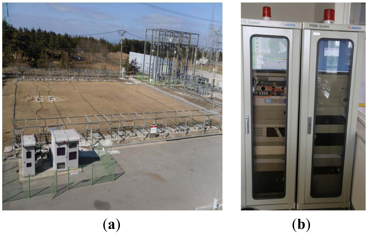
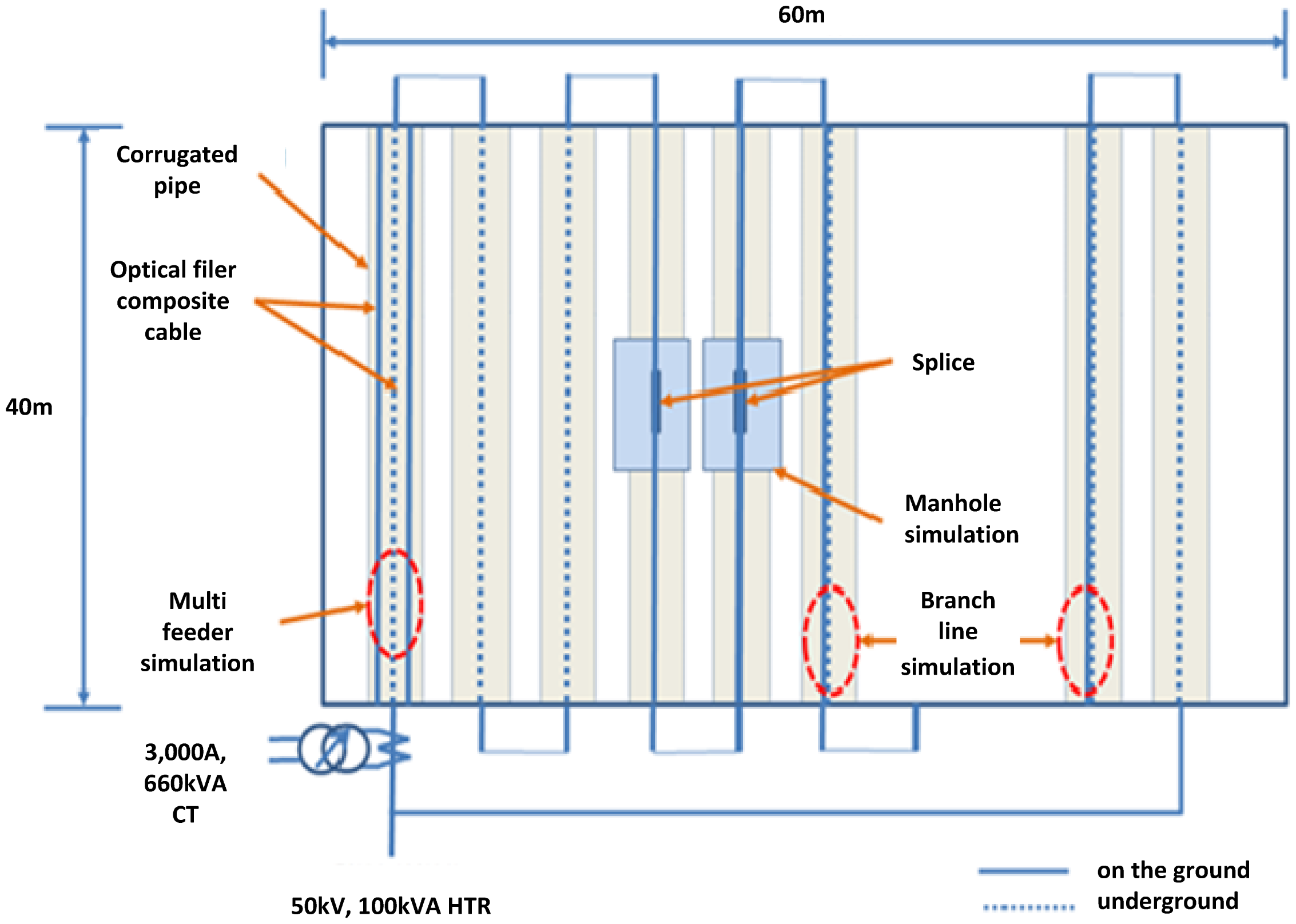
Figure 7 shows the test-bed configuration that was constructed to field test the intelligent cable monitoring system. The test line in the test-bed, which has the same structure as that of an actual underground distribution line, has about 1 km of underground line. In addition, multiple sections of the main line and branch line were constructed to confirm consequential monitoring. A manhole section to simulate the cable joint and manhole environment was designed as well. Furthermore, for the application of voltage and current to the test line similar to an actual distribution system, the following design was made, as shown in Figure 8, so that test-purpose outdoor voltage sources of 50 kV and 100 kV A and current sources of 3000 A/660 kV A may be connected.
The OFCPC, cable joint, and optical switch were installed in the test-bed, as shown in Figure 8. The constructed test-bed consists of an outdoor test line for the simulation of the underground distribution system and a central device for the operation and monitoring of the intelligent cable monitoring system.
4. Field Tests and Improvement
4.1. Short-Circuit Test
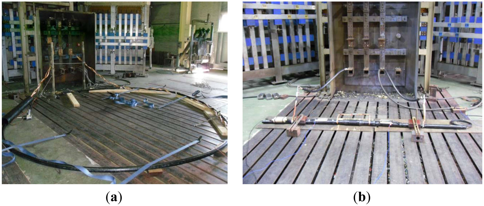
For the construction of the intelligent cable monitoring system and communication network using OFCPCs, the reliability of the optical fiber, cable joint, and optical joint box should be assured in fault situations such as short-circuit of the underground distribution system when laying the OFCPC to replace the power cable of the present underground distribution system. Therefore, as shown in Figure 9, a short-circuit test of the OFCPC and cable joint was conducted in accordance with IEC 60794-1-2 [8], the test procedure for optical fiber cables. During the short-circuit test, where a current of 10 kA was applied three times for 0.3 s each, no irregularity occurred after the communication status and loss were measured through the DTS. Accordingly, the reliability of the optical fiber was confirmed.
4.2. Field Test
4.2.1. Function Test
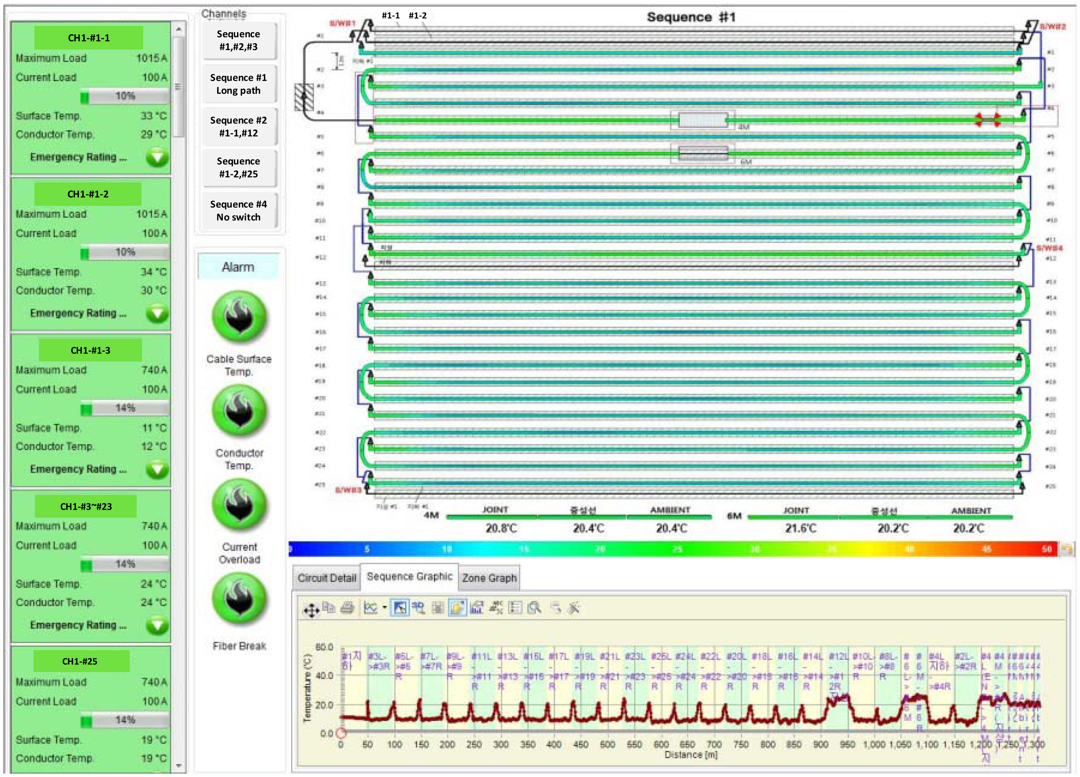
A function test was conducted on the test-bed of the intelligent cable monitoring system. The first test is to check the sequential monitoring function of the intelligent cable monitoring system. Sequential monitoring of cable temperature was performed for three feeder lines and two branch lines in the test-bed. As shown in Figure 10, a heat gun was used to check whether the system correctly monitored the temperatures of the multiple feeder lines and branch lines and performed the sequential monitoring of each line. Figure 10 shows the main screen of this system, which displayed the results of the performance of sequential monitoring when one of branch lines was heated by the heat gun. Next, the feasibility of measuring the temperatures of the cable joint kit and neutral line was confirmed on the structure of the designed cable joint. Thereafter, the water-tightness of the cable joint including the optical joint box was checked by placing a manhole in water. Lastly, communication loss variations due to a physical external force applied to the OFCPC and an open circuit fault were confirmed, and the generation of a quick alarm signal at the time of an open circuit fault was checked. The aforementioned function will locate a fault, such as an external fault of the underground distribution cable, when it occurs at an actual site.
4.2.2. Conductor Temperature Monitoring
4.2.2.1. Overview of Conductor Temperature Monitoring
Conductor Temperature Monitoring is a conductor temperature estimation algorithm that calculates the temperatures of all sections of the cable conductor by using the IEC-standard thermal circuit model data on the load currents that flow through power cables and the data on the sheath temperature of OFCPCs measured by DTS. Applying the thermal circuit model, it calculates the temperatures distributed on the cables, such as the temperatures of insulators, sheaths, and surfaces, in addition to conductor temperatures.
As shown in Figure 11, the entire thermal circuit is configured in accordance with the short duration model under IEC 60853-2, and individual thermal losses and thermal resistance values are configured in accordance with IEC 60287 series [9,10]. The cable thermal circuit in Figure 11 can be transformed into an equivalent circuit, as shown in Figure 12. The conductor temperature, insulator center temperature, sheath temperature, and jacket temperature are denoted by Θ1, Θ2, Θ3, and Θ4, respectively.
The parallel-connected thermal capacities in the equivalent circuit in Figure 12 are simplified into one thermal capacity. Thermal capacity is organized at each node of the circuit using the Kirchhoff's law; a state-variable differential equation that uses as variables the temperatures on individual parts of the cable is then expressed in the form of a matrix.
By obtaining the solutions of this matrix throughout all the sections in real-time, cable conductor temperatures are estimated in real-time and the cable temperature distribution is profiled.
4.2.2.2. Configuration of the Experiment
To verify the performance of conductor temperature monitoring, a temperature sensor was installed on the conductor of the OFCPC laid in the No. 1 duct in the test-bed, as shown in Figure 13. The current source connected to the test line supplied various currents (100–500 A) for 43 h to the OFCPC laid in the test-bed; conductor temperatures at these individual currents were then measured by the temperature sensor. The OFCPC's conductor temperatures measured by the temperature sensor were stored through the data-collecting device of the intelligent cable monitoring system.
At the same time, conductor temperatures were estimated by the conductor temperature monitoring function of the intelligent cable monitoring system. In conductor temperature monitoring, the air temperature of the intelligent cable monitoring system was set to 25 °C, and duct environments were simulated to be as similar as possible to those of the test-bed.
4.2.2.3. Experimental Results
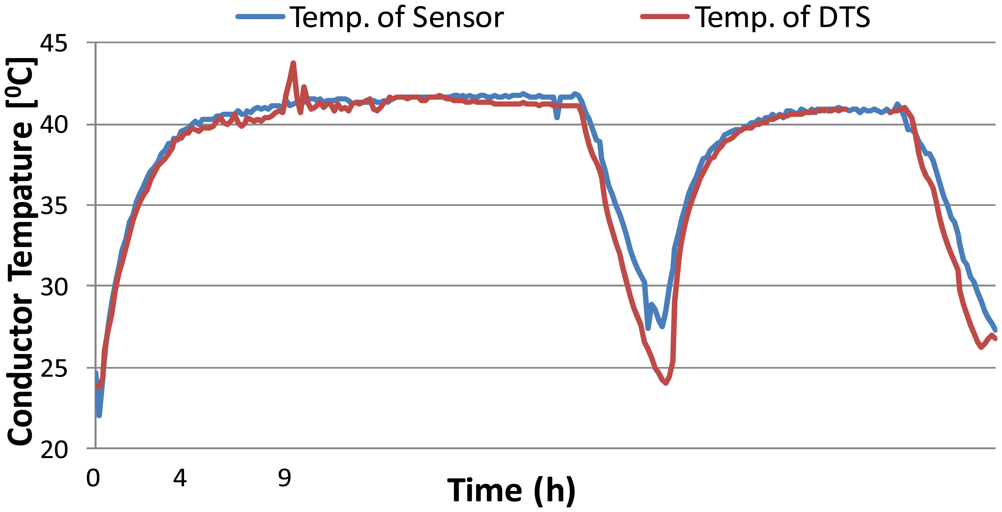
Cable conductor temperatures as measured by the temperature sensor and those measured by the intelligent cable monitoring system while 100∼500 A currents were supplied to the verification experiment line for 43 h are indicated in Figure 14. The currents supplied into the test line by the outdoor current source were equal to load current pattern of any actual distribution line. In Figure 14, the blue line is from temperature sensor and the red line is from the intelligent cable monitoring system. The two graphs show the same pattern, and the maximum difference between the measured cable conductor temperatures and the estimated ones is 5.7 °C. This suggests that such a difference occurred when the current dropped step-by-step, although there was almost no difference when the conductor temperatures were rising because the current was constant.
The intelligent cable monitoring system directly detects the temperature of optical fibers which are inserted between neutral lines of TR-CNCV cable. The conductor temperature is calculated from them with parameters concerning the underground environment. This indicates that the conductor temperature results obtained from the system are not more accurate compared with the directly detected ones, but the intelligent cable monitoring system and direct detection have produced similar results. Actually, 5.7 °C that is the maximum difference did not have much effect on dynamic ratings from calculations.
It is important that dynamic ratings of cables are calculated from estimation of conductor temperature with IEC series. Actually, utilities run distribution network with huge margin capacity. Therefore, if the intelligent cable monitoring system supports real dynamic ratings to operators of distribution system, it helps to increase the operating ampacity of distribution lines. The intelligent cable monitoring system can be applied to actual underground distribution lines for increasing the operating ampacity of the distribution system. In conclusion, based on these results, when the intelligent cable monitoring system with OFCPCs is applied to an actual field, the functions of the intelligent cable monitoring system can be utilized.
4.3. System Improvement
4.3.1. Test for DTS Optical Loss Characteristics
As shown in Figure 1, the DTS device inserts the laser pulse to optical fiber and then, the detector of the DTS device receives the backscattered light. Therefore, DTS optical loss is the difference between the inserted laser pulse and the detected backscattered light. Several optical switches are required to monitor multiple feeder lines and branch lines with a single channel. Furthermore, an optical joint for real-time monitoring at the cable joint of the underground distribution line is also necessary. If the intelligent cable monitoring system is applied, huge optical losses are likely to occur as the laser pulse is transferred to an optical fiber in the OFCPC because of the many joints and branch lines. If DTS optical loss is likely to increase as described above, the line length of the monitoring system developed in this study for application to the site may have to be limited. This is because, as shown in Table 1, the total loss of DTS has to be maintained below a certain level to secure DTS performance.
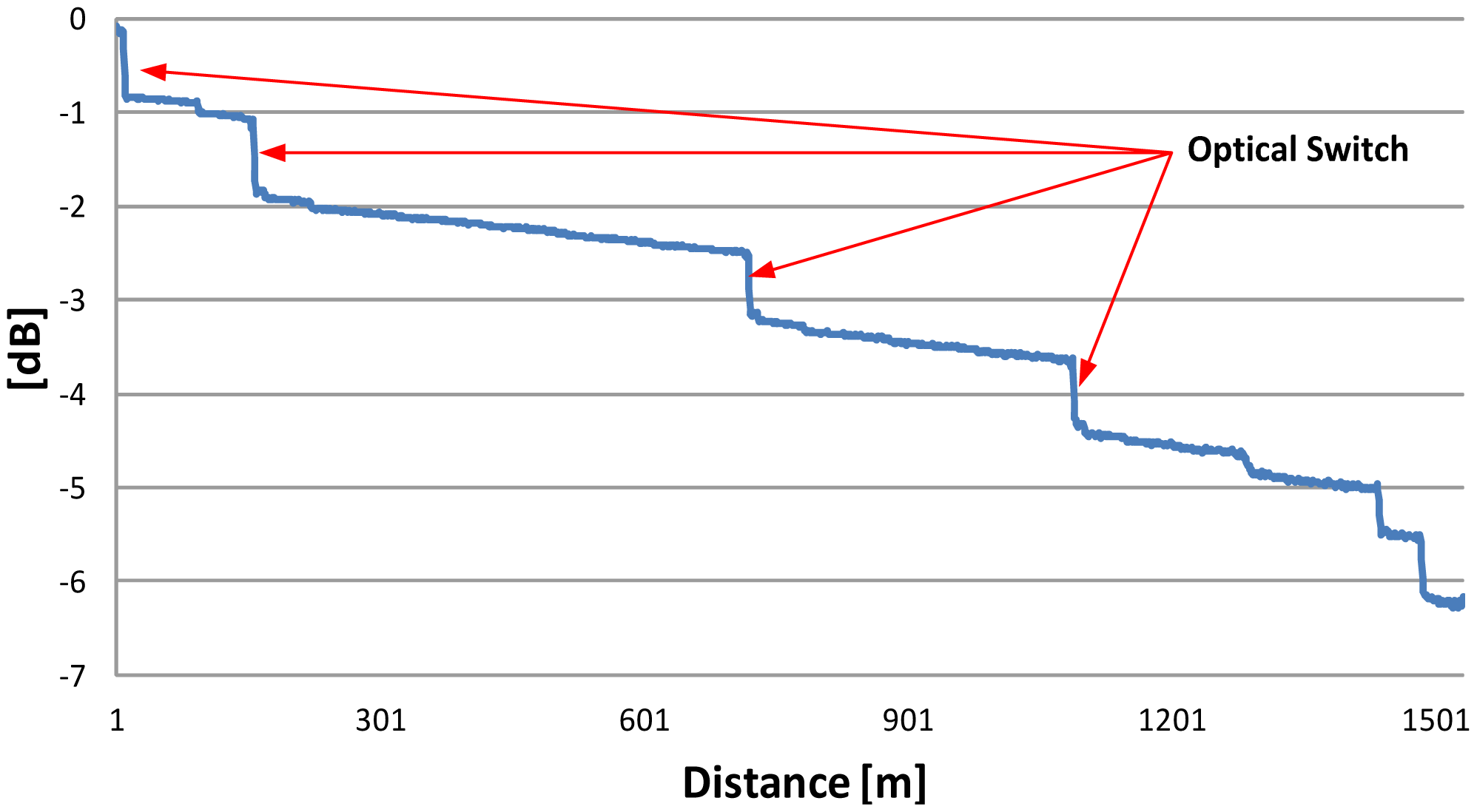
Therefore, in this study, the manufactured optical joint boxes and optical switches were installed on the test line of the test-bed to test the DTS optical loss characteristics of the monitoring system. The DTS optical loss of the test line in the test-bed was measured, as in Figure 15, and the cause of the loss of the total system was checked. The result showed that optical loss occurred in the optical fiber, optical joint box, and optical switch as well as during construction. Optical loss from the optical fiber was 0.7 db/km, which was the loss of the fiber itself; the loss from the optical joint box was 0.042 db on average, which had a very small effect on the total loss; and the loss of the optical switch was 0.6 db on average as shown Figure 15. These results imply that the monitoring system could apply to the test line in test-bed because total DTS optical loss is under the limitation level. To apply the monitoring system with lines longer than the test line and with many branch lines in an actual field; however, the loss from the optical switch needs to be reduced so that the DTS optical loss, which accounts for about 40% of the total loss, may be reduced.
4.3.2. Optical Switch Improvement
To extend the applicable line length of the intelligent cable monitoring system, the losses from the optical fiber and optical switch should be reduced. An inherent characteristic of an optical fiber is the loss of optical energy passing through the optical fiber with increasing distance. Therefore, optical fiber loss of about 0.7 db/km for a light source with a frequency band of 1060 nm used in the DTS seems to be unavoidable. As such, to extend the applicable line length of the system, reducing the loss from the optical switch would be more effective.
The layout of the internal components of the optical switch installed in the test-bed shows that the optical fiber is led in and connected to the optical switch in the optical switch box and subsequently connected to the branch circuit through the optical joint after the path through which light is transferred. It also consists of a main board for controlling them, optical switch control board, power supply, and communication board. Among these components, optical loss is generated at the optical fiber, optical joint and optical switch. Here, loss is influenced by the connection between the optical joint and the adapter part and loss is generated during the transfer to the branch circuit through the optical switch. Therefore, optical loss was minimized by changing the connection between the optical joint and the adapter to fusion splicing and by optimizing the optical switch to the optical source output for DTS.
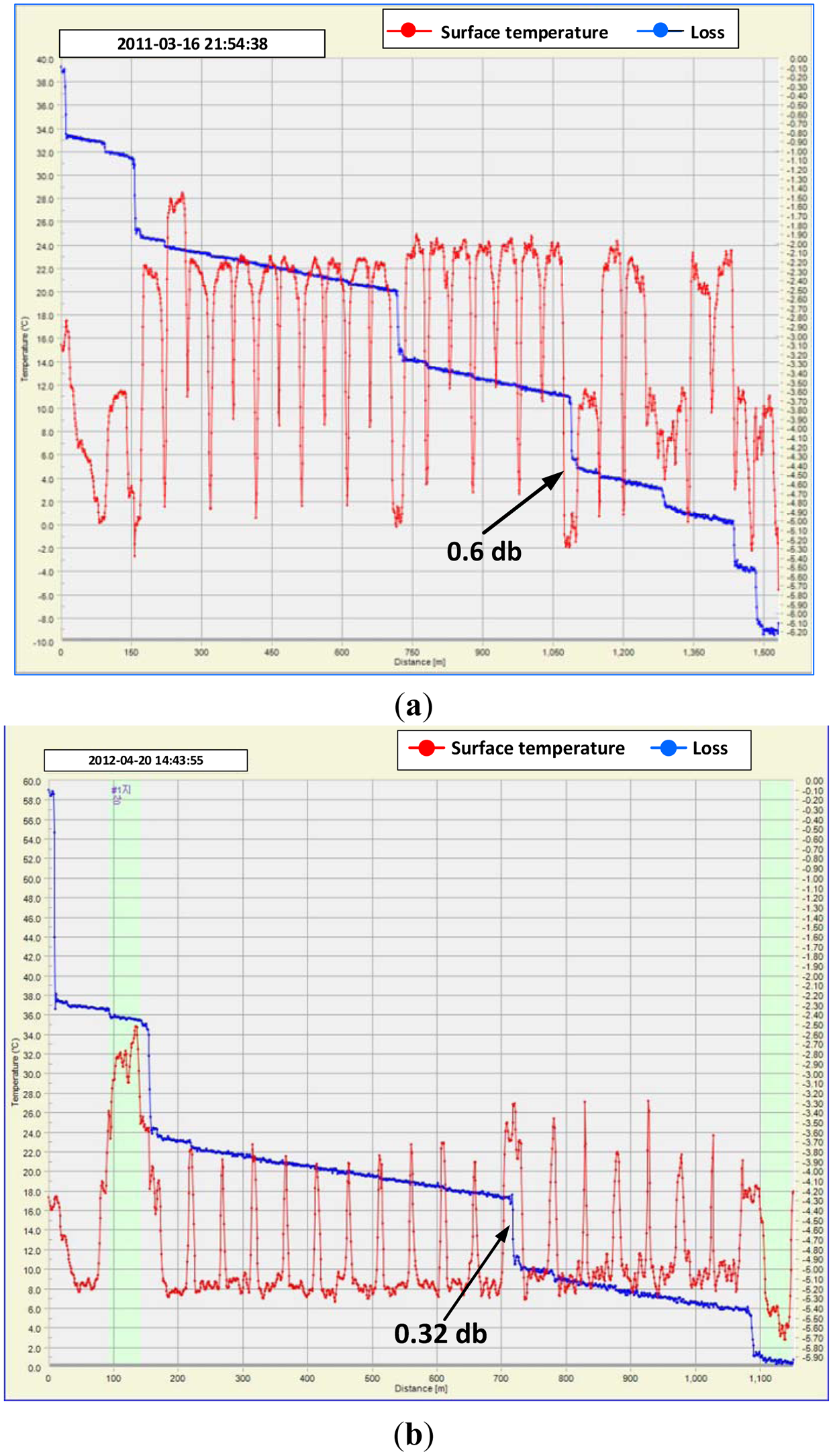
The improved optical switch was installed to replace the existing optical switch, which was built to simulate the branch line of the test-bed. Then the performance of the intelligent cable monitoring system was tested. As shown in Figure 16, the DTS optical loss of the improved optical switch, installed as replacement for the existing optical switch, was confirmed to be 0.32 db by a connection test with the central device; this was lower than the existing loss of 0.6 db.
In addition, as shown in Figure 17, the total monitoring function, including sequential monitoring of the branch lines, was performed correctly, making it possible to lengthen the line of this system at an actual site.
5. Conclusions
In this study, an intelligent cable monitoring system suitable for the underground distribution system was developed and field tested. Each of the components of the intelligent cable monitoring system, such as the OFCPC, cable joint, optical switch, HMI, was designed and manufactured with consideration of the conditions of the underground distribution system. For the field test of this system, a test-bed was constructed. Multiple feeder lines and branch lines were monitored with one-channel DTS; the temperature of the cable joint kit was measured; and the water-tightness of the connector was confirmed by placing it in water. In addition, a fault of the cable under a simulated external force and an open circuit fault of the cable were located. In addition, this intelligent cable monitoring system accurately measured cable temperature in real time in the measurement and comparison tests of conductor temperatures. Furthermore, in this study, the system was improved and its performance was tested by constructing a test-bed to ensure its applicability to an on-site underground distribution system. The applicable line length of the intelligent cable monitoring system could be extended when the DTS optical loss was reduced by improving the existing optical switch.
The developed intelligent cable monitoring system will soon be applied to an actual on-site underground power distribution line. The system applied to an actual field will reduce the number of faults and increase the operating ampacity of the underground distribution system. In addition, it will provide a communication network with the distribution automation system and will monitor the underground distribution cable as well as the existing intelligent distribution equipment so that operators can predict faults and shorten the fault recovery time for efficient and stable operation of the distribution system.
Acknowledgments
This research was made possible by the support of the Ministry of Knowledge Economy of the Republic of Korea.
Conflicts of Interest
The authors declare no conflict of interest.
References
- Downes, J.; Leung, H.Y. Distributed Temperature Sensing Worldwide Power Circuit Monitoring Applications. Proceedings of the International Conference on Power System Technology, Singapore, 21–24 November 2004; Volume 2, pp. 1804–1809.
- Goehlich, L.; Donazzi, F.; Fricke, W. First Commercial Application of New Monitoring Systems against Water Ingress and Over Temperatures in HV-XLPE Cables. Proceedings of the 8th International Conference on Dielectric Materials, Measurements and Applications, Edinburgh Scotland, UK, 17–21 September 2000; pp. 452–457.
- Marie-Helene, L.; Anders, G.J. Real Time Monitoring of Power Cables by Fibre Optic Technologies Tests, Applications and Outlook. Proceedings of the International Conference on Insulated Power Cables (JICABLE), Paris, France, 22–26 June 2003.
- Goehlich, L.; Kuschel, M. Advantages of HV Cable Transmission Links by Using Real Time Thermal Rating (RTTR) and Water Monitoring. Proceedings of the 7th International Conference on AC-DC Power Transmission, London, UK, 28–30 November 2001; pp. 27–32.
- Bevan, J. Design, development and installation of an optical phase conductor on 33 kV wood pole line. IET J. Mag. 1995, 9, 277–281. [Google Scholar]
- Testing and Performance for Optical Ground Wire (OPGW) or Use on Electric Utility Power Lines; Institute of Electrical and Electronics Engineers (IEEE) Standard 1138; IEEE Press: Washington, DC, USA, 2009.
- Zhang, X.; Jiang, X. The Application of Fiber Optic Distributed Temperature Sensor to Fault Detection of XLPE Insulated Underground Cable. Proceedings of the 6th International Conference on Properties and Applications of Dielectric Materials (ICPADM), Xi'an, China, 21–26 June 2000; Volume 1, pp. 154–156.
- Optical Fiber Cables—Part 1-2: Generic Specifications—Basic Optical Cable Test Procedures; International Electrotechnical Commission (IEC) Standard 60794-1-2; IEC Press: Geneva, Switzerland, 2003.
- Calculation of the Cyclic and Emergency Current Rating of Cables—Part 2: Cyclic Rating of Cables Greater than 18/30 (36) kV and Emergency Ratings for Cables of All Voltages; International Electrotechnical Commission (IEC) Standard 60853-2; IEC Press: Geneva, Switzerland, 2008.
- Electric Cables—Calculation of the Current Rating; International Electrotechnical Commission (IEC) Standard 60287 Series; IEC Press: Geneva, Switzerland; pp. 1993–2012.


| Description | Specifications |
|---|---|
| Temperature accuracy | ±1.0 °C |
| Temperature resolution | 1.0 °C |
| Measurement time | 30 s |
| Sampling resolution | 1 m |
| Spatial resolution | 1.5 m |
© 2014 by the authors; licensee MDPI, Basel, Switzerland. This article is an open access article distributed under the terms and conditions of the Creative Commons Attribution license ( http://creativecommons.org/licenses/by/3.0/).
Share and Cite
Cho, J.; Kim, J.-H.; Lee, H.-J.; Kim, J.-Y.; Song, I.-K.; Choi, J.-H. Development and Improvement of an Intelligent Cable Monitoring System for Underground Distribution Networks Using Distributed Temperature Sensing. Energies 2014, 7, 1076-1094. https://doi.org/10.3390/en7021076
Cho J, Kim J-H, Lee H-J, Kim J-Y, Song I-K, Choi J-H. Development and Improvement of an Intelligent Cable Monitoring System for Underground Distribution Networks Using Distributed Temperature Sensing. Energies. 2014; 7(2):1076-1094. https://doi.org/10.3390/en7021076
Chicago/Turabian StyleCho, Jintae, Jae-Han Kim, Hak-Ju Lee, Ju-Yong Kim, Il-Keun Song, and Joon-Ho Choi. 2014. "Development and Improvement of an Intelligent Cable Monitoring System for Underground Distribution Networks Using Distributed Temperature Sensing" Energies 7, no. 2: 1076-1094. https://doi.org/10.3390/en7021076