An Optimal Reactive Power Control Strategy for a DFIG-Based Wind Farm to Damp the Sub-Synchronous Oscillation of a Power System

Abstract
: This study presents the auxiliary damping control with the reactive power loop on the rotor-side converter of doubly-fed induction generator (DFIG)-based wind farms to depress the sub-synchronous resonance oscillations in nearby turbogenerators. These generators are connected to a series capacitive compensation transmission system. First, the damping effect of the reactive power control of the DFIG-based wind farms was theoretically analyzed, and a transfer function between turbogenerator speed and the output reactive power of the wind farms was introduced to derive the analytical expression of the damping coefficient. The phase range to obtain positive damping was determined. Second, the PID phase compensation parameters of the auxiliary damping controller were optimized by a genetic algorithm to obtain the optimum damping in the entire subsynchronous frequency band. Finally, the validity and effectiveness of the proposed auxiliary damping control were demonstrated on a modified version of the IEEE first benchmark model by time domain simulation analysis with the use of DigSILENT/PowerFactory. Theoretical analysis and simulation results show that this derived damping factor expression and the condition of the positive damping can effectively analyze their impact on the system sub-synchronous oscillations, the proposed wind farms reactive power additional damping control strategy can provide the optimal damping effect over the whole sub-synchronous frequency band, and the control effect is better than the active power additional damping control strategy based on the power system stabilizator.1. Introduction
Series capacitive compensation is an important approach to improve the transfer capability and transient stability of existing transmission systems. However, the extensive use of series compensation can cause subsynchronous resonance (SSR), in which electrical networks exchange energy with the generator shaft system at frequencies less than the nominal frequency of the transmission line; this phenomenon results in turbogenerator shaft failure and instability of the power system [1,2].
To prevent the turbogenerator shaft from failing and to depress SSR oscillations, flexible AC transmission system (FACTS) devices (e.g., SVC, TCSC, STATCOM) [3–12], are widely utilized to effectively relieve SSR. These devices should be enhanced with an auxiliary damping controller to provide the extra damping characteristic. Although FACTS devices can depress SSR, installation of such devices is expensive, so utilizing FACTS may not be cost effective.
Wind energy is the fastest-growing form of renewable energy in the world because it is clean, non-polluting, and abundant. Wind farms with a scale of hundreds of MW level are increasingly being developed and connected to power systems. Doubly fed induction generators (DFIGs) are widely used in wind power plants because of their capability to decouple control of real and reactive power. With the integration of large-scale wind farms into power systems, some researchers have used the control capability of DFIG to damp power system oscillations; however, most studies have focused on damping inter-area low-frequency oscillations [13–17], whereas relatively very few studies have reported on damping SSR. [18] proposed the auxiliary control of a DFIG-based wind farm to damp SSR oscillations in nearby turbogenerators by addition of a supplemental signal at the grid-side converter of the DFIG. However, the auxiliary controller requires the precise measurement of the angular speed deviation of each shaft segment. The controller parameters are obtained by a time-consuming trial-and-error approach, and the damping mechanism is also not analyzed. Therefore, the use of DFIG-based wind farms to damp SSR oscillations in the entire subsynchronous frequency band and the damping mechanism should be further analyzed.
This study presents the application of auxiliary damping control to the rotor-side converter (RSC) of a DFIG to damp SSR. A transfer function between turbogenerator speed and the output reactive power of wind farms was introduced to derive the analytical expression of damping. The effect of the reactive power of the DFIG-based wind farms on system damping was analyzed, and the phase range to obtain positive damping was determined. Then, a new auxiliary damping control strategy was proposed. The PID phase compensation parameters of the auxiliary damping controller were optimized by a genetic algorithm to obtain optimum damping in the entire sub-synchronous frequency band. Finally, the IEEE first benchmark model, modified by the inclusion of the DFIG-based wind farms, is used to demonstrate the performance of the proposed auxiliary damping control to suppress SSR oscillations by time domain simulation analysis with the use of DigSILENT/PowerFactory.
2. Power System Model with DFIG-Based Wind Farm
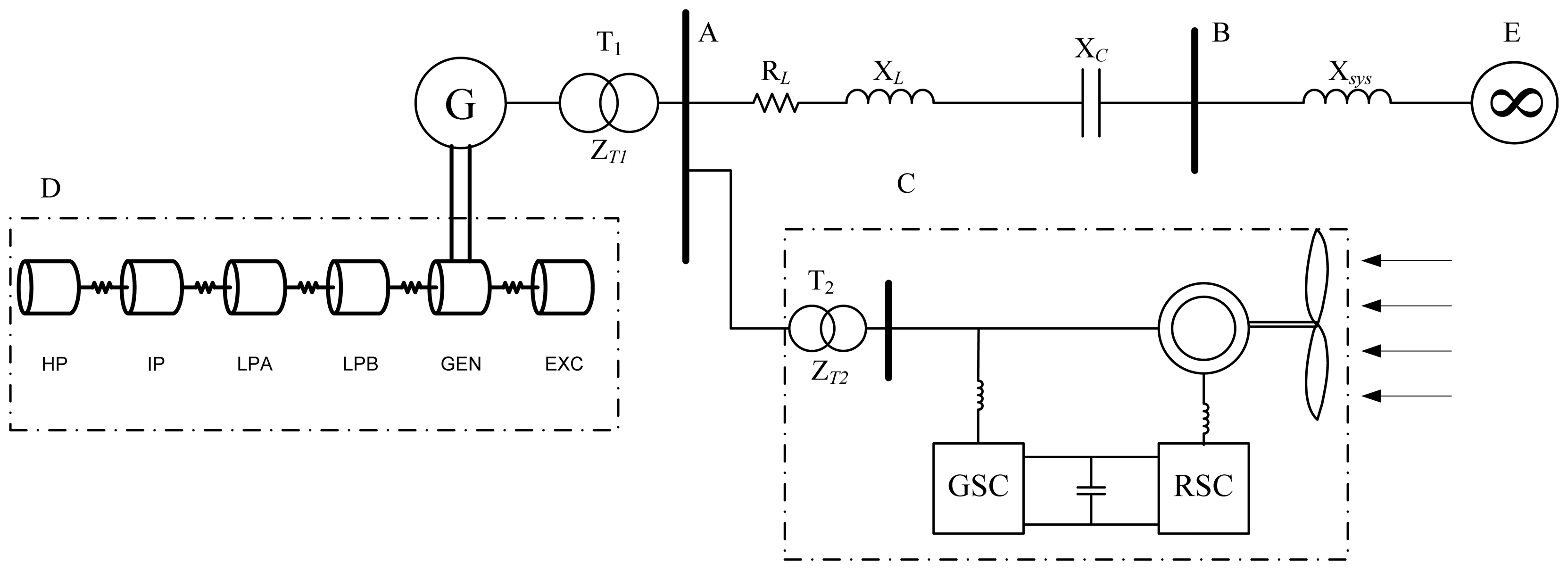
To evaluate the effectiveness of the proposed strategy on auxiliary damping control, the well-known IEEE first benchmark model, modified by the inclusion of DFIG-based wind farms, is used (Figure 1). The system consists of an 892.4 MWA turbogenerator connected to an infinite bus through a radial series-compensated line. The rated voltage is 539 kV, and the frequency is 60 Hz. A DFIG-based wind farm (200 MW from the aggregation of 2 MW units) is connected to bus A via a transformer. Figure 1 shows that G represents the turbogenerators; C, the DFIG-based wind farms; D, the turbine shaft system; and E, the infinite power grid. RL + jXL is the power transmission line impedance, Xc is the captance of the series compensation capacitor, and Xsys is the reactance of the transmission line to the infinite power grid. The complete electrical and mechanical data are given in the Appendix.
2.1. Turbogenerator Shaft System Model
The turbogenerator shaft system consists of six shaft segments, namely, a high-pressure turbine (HP), an intermediate-pressure turbine (IP), a low-pressure turbine (LPA), a low-pressure turbine (LPB), the generator (GEN), and the exciter (EXC). All masses are mechanically connected to one another by elastic shafts. The shaft system motion equation is described as follows:
2.2. DFIG-Based Wind Turbine Model
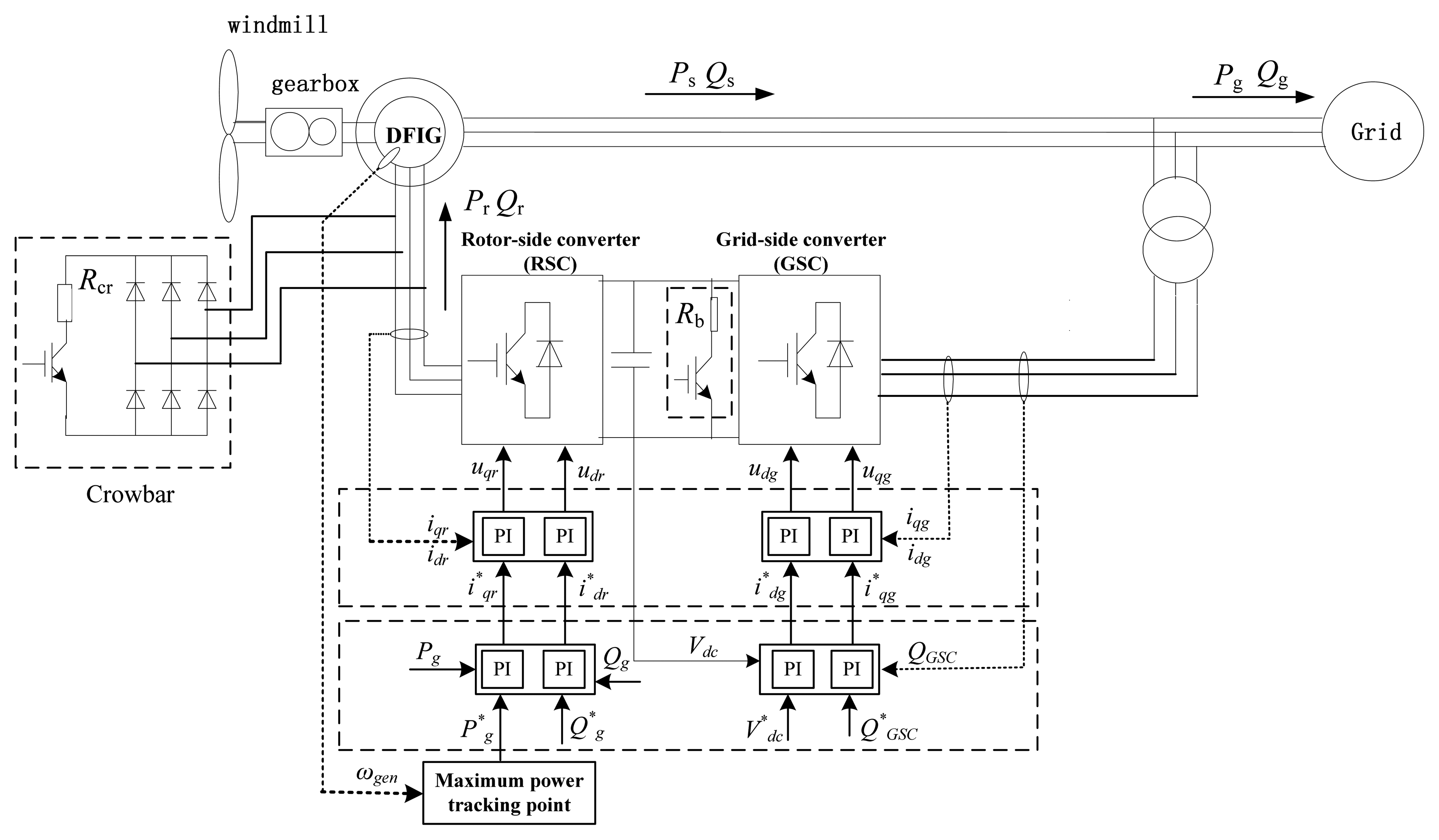
The typical DFIG configuration consists of a wound rotor induction generator, with the stator directly connected to the grid and the rotor interfaced through a back-to-back partial scale power converter, as shown in Figure 2. The back-to-back converter is a bi-directional power converter that consists of two conventional voltage source converters (an RSC and a grid side converter or GSC) and a common dc-bus. Both GSC and RSC contain an internal current controller and an external power controller. The slow power controller provides a reference current to the fast current controller, which further regulates the rotor current to the reference value. The RSC aims to independently control the active power of the generator and the reactive power produced or absorbed from the grid. The GSC aims to keep the dc-link voltage constant, regardless of the magnitude and direction of the rotor power and to guarantee converter operation with unity power factor (zero reactive power). This requirement means that the GSC exchanges only active power with the grid, so the transmission of reactive power from the DFIG to the grid is done only through the stator [18,19].
3. Damping Analysis with the Reactive Power Control of Wind Farms
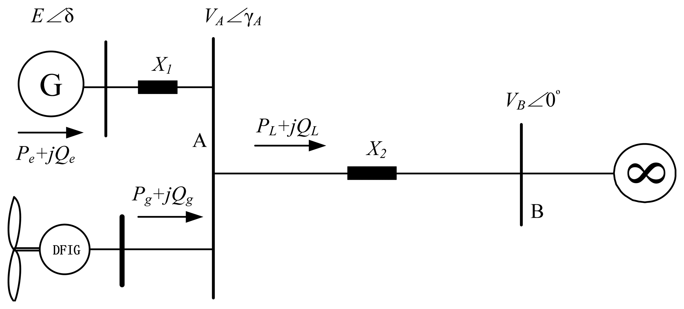
To analyze the mechanism of influence of the DFIG-based wind farms on system SSR damping, the system model in Figure 1 is simplified in Figure 3, where E is the quadrature-axis transient electromotive force of turbogenerator G; VA is the voltage of bus A; VB is the infinite bus voltage; δ, γA is the phase angle difference between E, VA, and VB; Pe, Qe are the active/reactive power output of the turbogenerator; Pg, Qg are the active/reactive power output of the DFIG-based wind farms; PL, QL are the active/reactive power flow through the transmission line; and X1, X2 are the reactance parameters.
The output active/reactive power Pe/Qe of the turbogenerator can be expressed as:
In the following small signal analysis derivation, the variation of the reactive power from DFIG based wind farm is assumed to only led to minor amplitude changes of the bus voltage VA, the quadrature-axis transient electromotive force of turbo-generator E could be regarded as a constant. Thus, the deviation analysis of Equations (3) and (4) can lead to:
Considering the minor amplitude changes of the bus voltage VA is assumed to be only caused by the variation of the reactive power from DFIG based wind farm, the increment ΔVA can be obtained as:
Then, according to the active power balance of the transmission line, the next linearization equation can be obtained:
Substitute Equation (5) into above equation, the next equation can be obtained:
Next, Equations (7) and (9) was substituted into Equation (5), and ΔPe can be rewritten as follows:
The above equation indicates that the ΔPe has two items. The first item is proportional to the Δδ, which can produce synchronous torque. The second item is related to DFIG reactive power ΔQg, which may produce positive or negative damping effects on the system according to the phase relationship between ΔQg and turbogenerators Δω. To analyze the damping effects of reactive power ΔQg on the system, the transfer function Gωq(s) based on turbogenerator speed ω(t) and the output reactive power Qg(t) of the wind farms (referred to as the reactive-speed transfer function) are derived by using the linearization state equation of DFIG in [20,21]:
Also, to analyze the damping effects of active power ΔPg on the system, a transfer function similar to above equation (referred to as the active-speed transfer function) can be derived:
Given the sinusoidal microvariation of turbo-generators Δω with amplitude A and frequency ω0 (Δω = A sin(ω0t)), the microvariation of reactive power ΔQg can be expressed as follows:
To analyze the damping effects of the last item of Equation (10), we define the component of the last item on Δω as reactive power damping ratio Dωq.:
When the phase angle between the range , Dωq > 0 and Dωq were proportional to |Gωq(jω)|. Therefore, to enable the reactive power ΔQg of the DFIG-based wind farms to offer positive damping on SSR, the phase angle range of active-speed transfer function Gωq(s) in the subsynchronous frequency band (62.8 rad/s to 314 rad/s) should be satisfied as follows:
4. Design of SSR Auxiliary Damping Controller
4.1. Structure of the SSR Auxiliary Damping Control
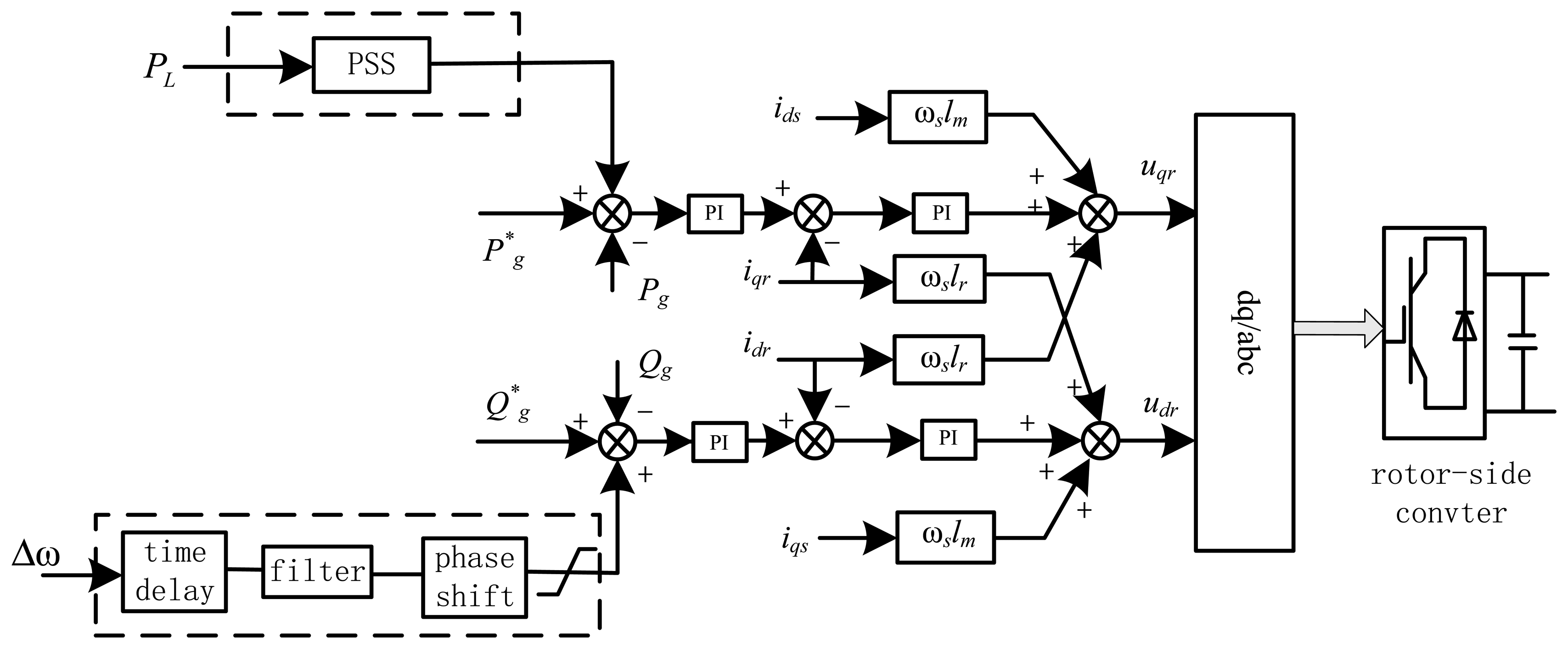
The diagram of the auxiliary damping control system is shown in Figure 4. SSR damping is achieved by addition of a supplementary signal at the reactive power loop of the RSC. Turbogenerator speed Δω served as the input signal; after processing by time delay, filter, and phase shift, a supplementary signal output of dynamic reactive power ΔQg was provided and added at the reactive power loop of RSC. Also, the method of utilizing power system stabilizer (PSS) added at the active power loop of the RSC is shown in Figure 4 [22,23], where Pg and Qg are the measured values of active/reactive power from the output ends of wind farms; P*g, Q*g are the set values of the active/reactive power of the converters, respectively; idr, iqr are the rotor current values of Shaft d and Shaft q; ids, iqs are the stator current values of Shaft d and Shaft q; udr, uqr are the rotor voltages of Shaft d and Shaft q; lr, lm are the rotor self-inductance and stator mutual inductance; and ωs is the slip angular frequency.
For an improved approximate time delay effect in the entire sub-synchronous frequency band, we use Pade approximation for the time delay:
After time delay processing, the signal of turbo-generator speed deviation Δω was processed by the Butterworth filter to obtain the SSR modal component.
To efficiently compensate for the phase in the entire subsynchronous frequency band to satisfy the phase-frequency characteristics of damping SSR from Equation (15), the proposed transfer function of the PID phase shift compensation is as follows:
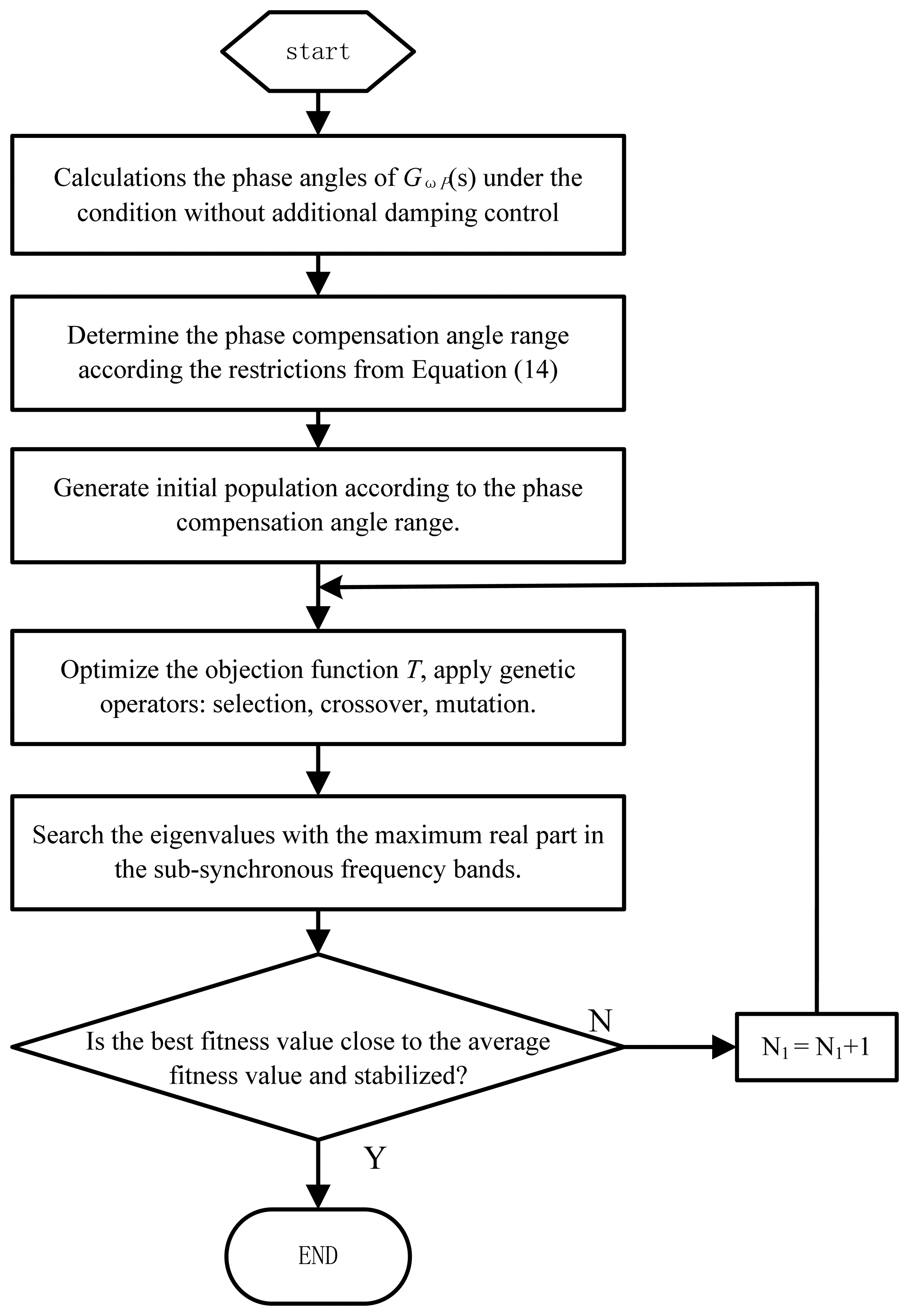
4.2. Optimization of the PID Phase Compensation Parameters
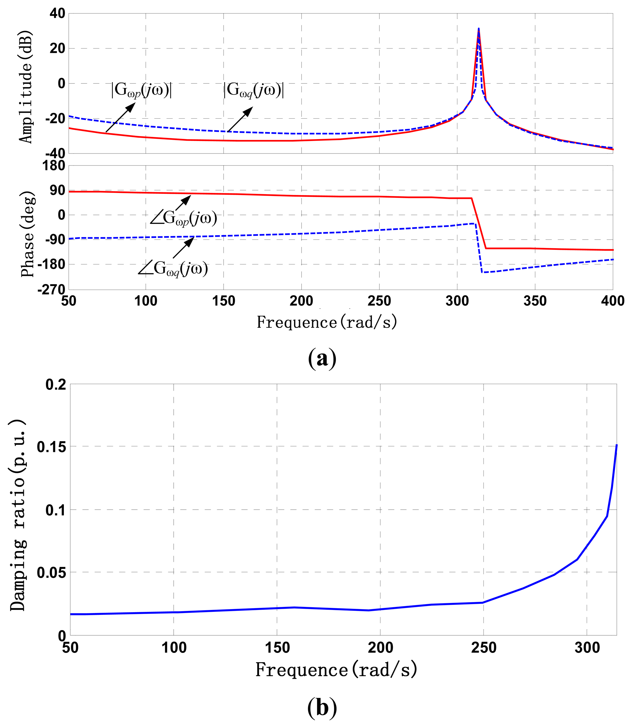
To ensure that auxiliary damping controllers can provide effective positive damping in subsynchronous frequency bands, the proper phase compensation angle must be selected. Before calculating the phase compensation angle range, we must first determine the initial damping ratio and the initial phase angle range without auxiliary damping control. The amplitude-frequency and phase-frequency characteristic curve of Gωq(jω) and the damping ratio curve of Dωq were obtained, as shown in Figure 5a,b.
Also, for comparision with active power addition damping control, the amplitude-frequency and phase-frequency characteristic curve of Gωp(jω) were shown in Figure 5a. From the Figure 5a we can see that the log amplitude of Gωp(jω) is negative and smaller than the Gωq(jω) in entire subsynchronous frequency band. This would mean that |Gωp(jω)| will be mCuch samller than |Gωq(jω)| and the reactive power significantly affect the system damping more than active power.
Next, based on the condition of the phase compensation angle range for positive damping from Equation (15), the optimal parameters for PID phase control can be obtained. These parameters enable the controller to obtain effective damping controls in the entire subsynchronous frequency band. In our study, the goal was to make the eigenvalue of the closed-loop system approach the left of the complex plane as much as possible. The objective function is:
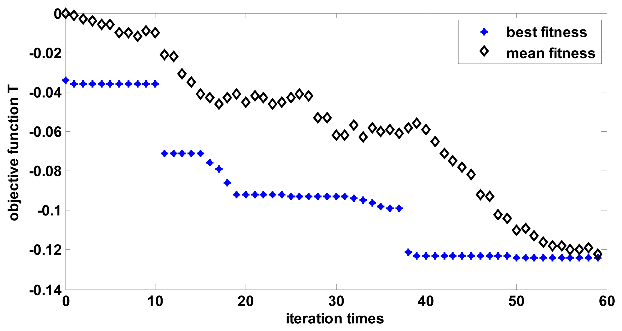
In the figure, N1 is the total number of iterations in the optimization. The value range of PID parameters and compensation level are set as: KP∈(0.1,10), TI∈(1,100), TD∈(1,100), XC/XL∈(0.2,0.8). According to the above calculation process for the optimization of the phase compensation parameters of the PID controller, the changes in best fitness and mean fitness are shown in Figure 7.
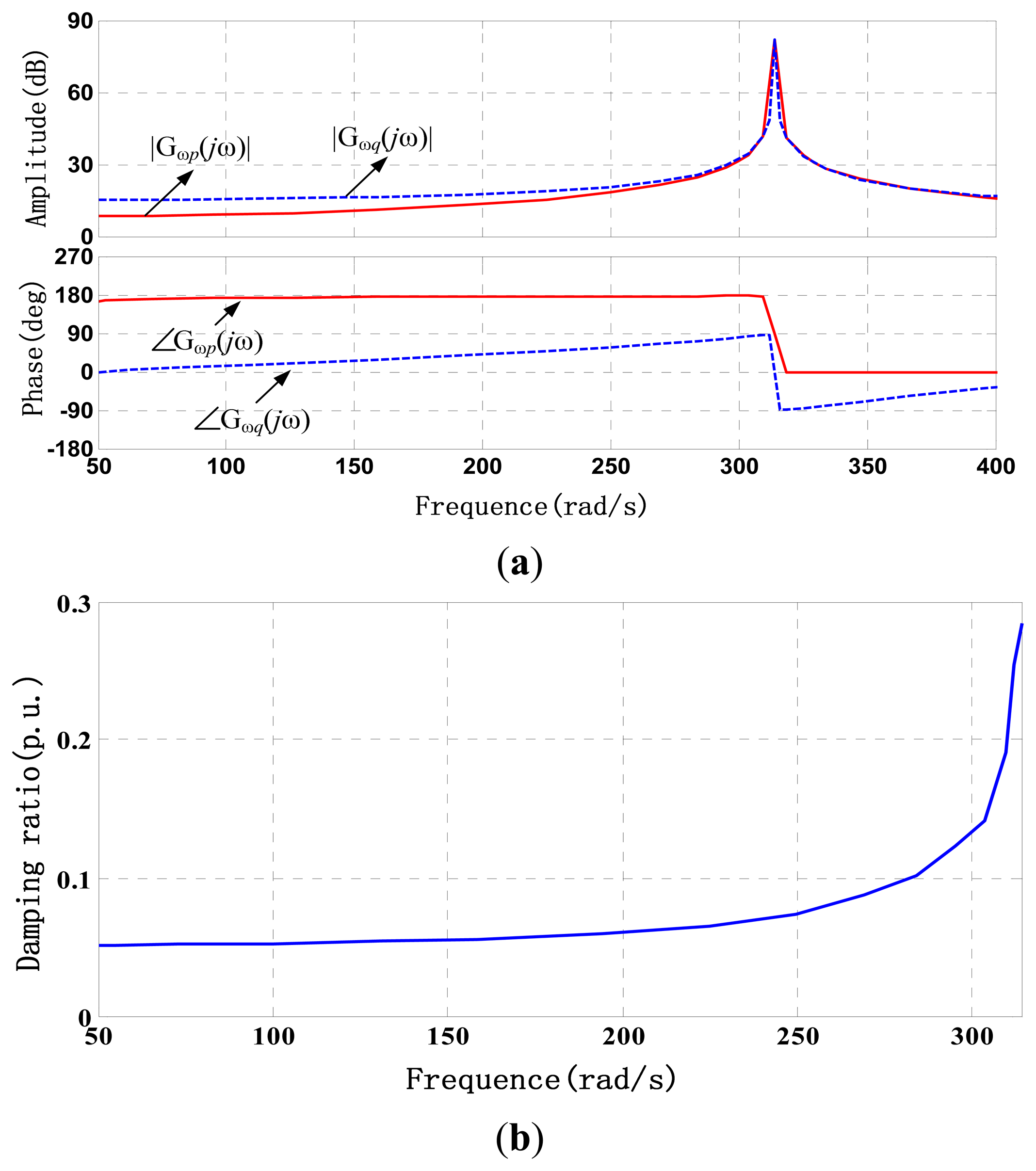
After the PID parameters optimization, the KP = 2.5, TD = 2.8ms, TI = 5.2ms. Based on the optimization parameters of the PID controller, the amplitude-frequency and phase-frequency characteristic curve of Gωq(jω) and the damping ratio curve of of Dωq with the auxiliary damping control strategy were obtained, as shown in Figure 8a,b. Also, for comparision, the amplitude-frequency and phase-frequency characteristic curve of Gωp(jω) with the active power addition damping control based with PSS were shown in Figure 8a.
Comparison of Figures 5 and 8 indicates that after the introduction of auxiliary damping control strategy based on the reactive power loop, the phase angle range of reactive-speed Gωq(s) was also between −π/2∼−π/2, which ensures that the positive damping can be provided in the whole sub-synchronous frequency band. Furthermore, the damping ratio curve shows that the damping ratio significantly increased compared with that without auxiliary damping control.
Meanwhile, from Figure 8a we can also see that the log amplitude of Gωp(jω) is smaller than the Gωq(jω) in entire subsynchronous frequency band. This would also mean that |Gωp(jω)| will be much samller than |Gωq(jω)|, and the reactive power significantly affect the system damping more than active power.
5. Time Domain Simulation Results
To evaluate the effectiveness of the proposed auxiliary damping control to mitigate SSR, the IEEE first benchmark model, modified by the inclusion of DFIG-based wind farms, was simulated with the use of the simulation program DIgSILENT/PowerFactory (DIgSILENT GmbH, Gomaringen, Germany). The compensation level XC/XL is to 0.55. At t = 0.1 s, a three-phase short-circuit fault occurred at bus A and lasted for 0.025 s. Since the considered grid disturbances are much faster than wind speed variations, for simplicity the wind speed can be assumed to be constant.
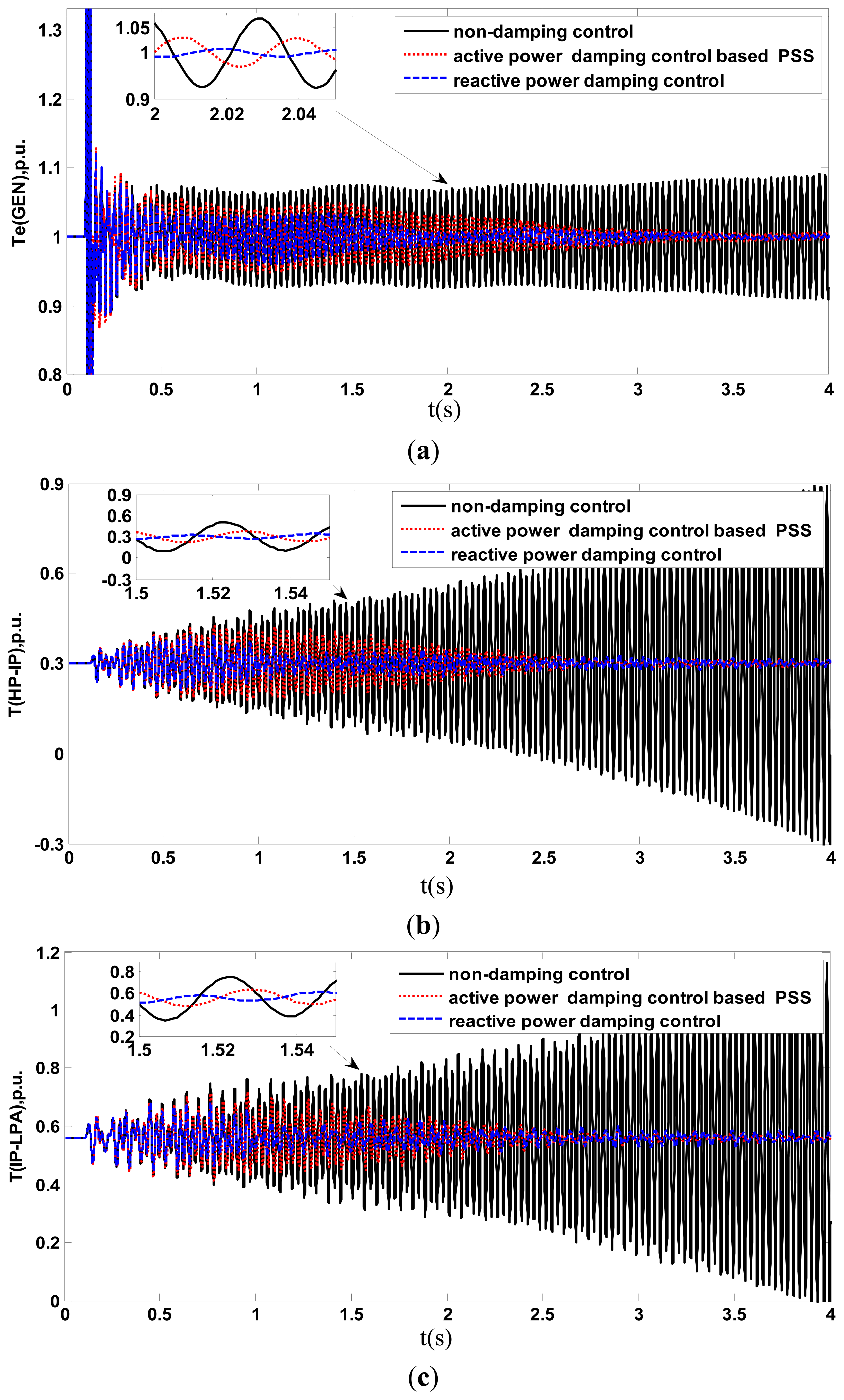
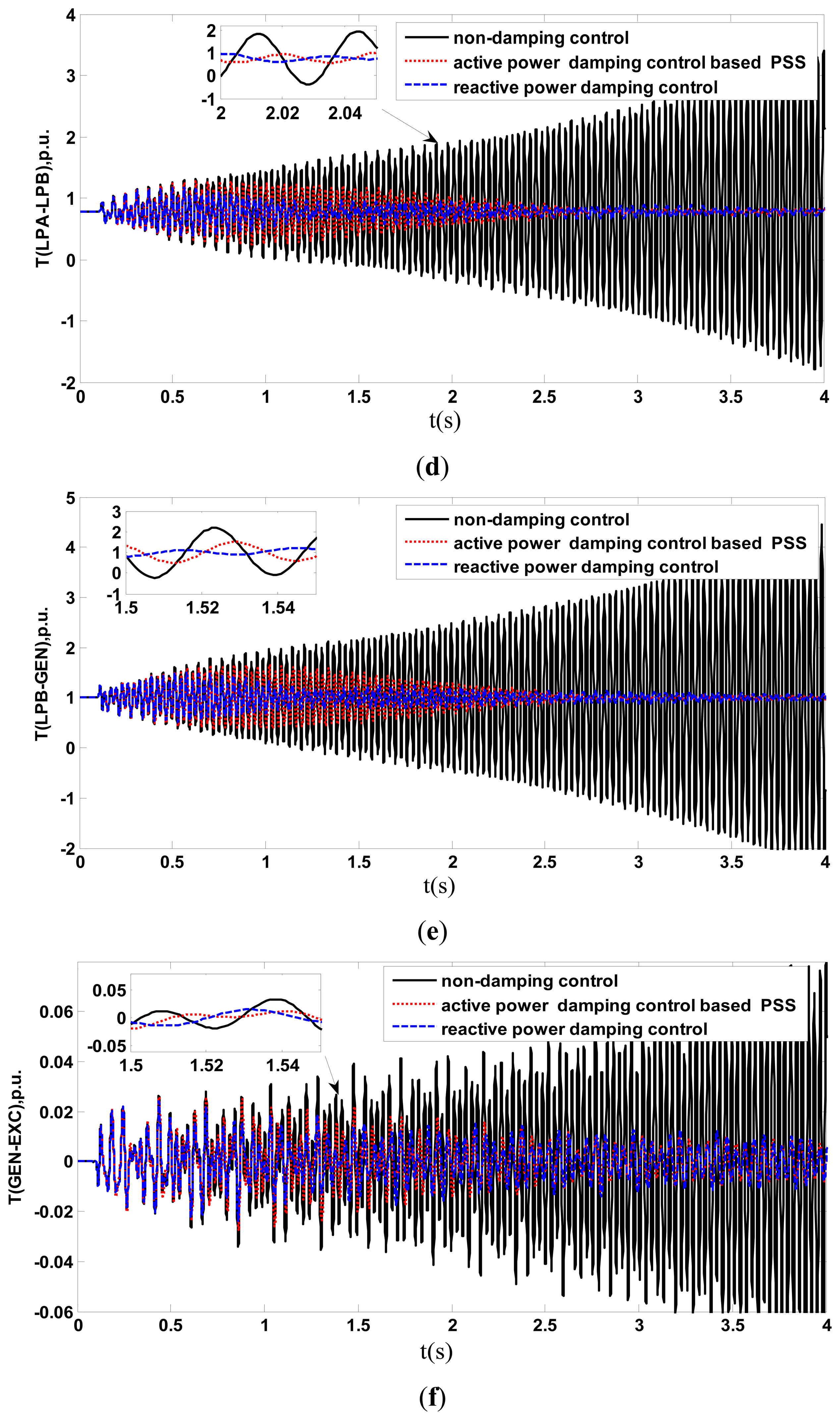
The time responses of the turbo-generator torques and the angular acceleration during and after clearing fault with auxiliary damping control are shown in Figure 9. Also, an active power addition damping control based with power system stabilizator(PSS) and without auxiliary damping are shown in Figure 9 for comparison. Figure 10 shows the DFIG electrical torque and the supplementary signal output of dynamic active power ΔQg added at the active power loop of RSC.
Figure 9 shows that when the auxiliary damping control of DFIG is not in service, the turbogenerator shaft electrical torque, torsional torque, and angular acceleration exhibit severe torsional amplifications (instability) after clearing faults. When the auxiliary damping control of DFIG is in service, the turbogenerator shaft electrical torque, torsional torque, and angular acceleration are stable. Meanwhile, compared with the active power addition damping control based with PSS, the auxiliary damping control based on reactive power exhibit samller torque fluctuation. These results demonstrate the effectiveness of the proposed auxiliary damping control in damping the SSR and was superior to active power addition damping control based with PSS. Figure 10a also shows that the adverse effect of SSR is extended to DFIG when the auxiliary damping control of DFIG is not in service and the DFIG electrical torques also exhibit severe torsional amplifications (instability). When the auxiliary damping control of DFIG is in service, a supplementary signal output of dynamic reactive power ΔQ is added at the reactive power loop of RSC, as shown in Figure 10b. The DFIG electrical torque is stable.
6. Conclusions
A novel auxiliary damping control strategy to depress SSR with the use of the reactive power control of DFIG-based wind farms has been presented in this study. Modulating the reactive power of the rotor-side converter of the DFIG to provide a positive damping component to facilitates SSR damping.
First, through a theroetical analysis, a transfer function between turbogenerator speed and the output reactive power of wind farms was introduced to derive the analytical expression of the damping ratio. Next, the effect of the reactive power of the DFIG-based wind farms on SSR damping was analyzed, and the phase range to obtain positive damping was determined. Then, using genetic algorithm, the optimum PID phase compensation parameters of the auxiliary damping controller were optimized to obtain the optimum damping in the entire sub-synchronous frequency band. Finally, the effectiveness of the proposed auxiliary damping control in suppressing SSR oscillations is demonstrated through time domain simulation of the modified IEEE first benchmark model. Results show that compare with no damp control and active power addition damping control based with PSS, the proposed auxiliary damping control can effectively damp SSR oscillations.
Acknowledgments
This study was supported by the National Natural Science Foundation of China (51377184), the International Science and Technology Cooperation Program of China (2013DFG61520), the Fundamental Research Funds for the Central Universities (CDJXS10151152), the Fundamental Research Funds for the Central Universities (CDJZR12150074), and the integration and demonstration program of Chongqing (CSTC2013JCSF70003). The authors are grateful for the supports.
Conflicts of Interest
The authors declare no conflict of interest.
Appendix
Network parameters:
RL = 0.02 pu, XT = 0.14 pu, Transformer ratio 26/539 kV, XL = 0.50 pu, Xsys = 0.06 pu.
Turbo-generator parameters:
Xaσ = 0.13 pu, Xd = 1.79 pu, , , Xq = 1.71 pu, , , , , , .
Shaft parameters:
HHP = 0.092897, HIP = 0.155589, HLPA = 0.858670, HLPB = 0.884215, HGEN = 0.868495, HEXC = 0.0342165, KHP-IP = 19.303 pu/rad, KIP-LPA = 34.929 pu/rad, KLPA-LPB = 52.038 pu/rad, KLPB-GEN = 70.858 pu/rad, KGEN-EXC = 2.82 pu/rad.
DFIG parameters:
Rated power: 2 MW, Rated voltage: 690 V, Rated frequency: 60 Hz, wind speed: 11 m/s, Rs = 0.00832 pu, Lls = 0.218 pu, Rr = 0.00935 pu, Llr = 0.236 pu, Lm = 2.905 pu, Hg = 0.5 s, Hw = 4.45 s, Ks = 0.31 pu/rad.
The derived expressions of Gωq(s) and Gωp(s) are given by:
References
- Maciej, O.; Balcerek, P.; Orkisz, M. Effective method of subsynchronous resonance detection and its limitations. Int. J. Electr. Power Energy Syst. 2012, 43, 915–920. [Google Scholar]
- Khazaie, J.; Mokhtari, M.; Khalilyan, M.; Nazarpour, D. Sub-synchronous Resonance damping using Distributed Static Series Compensator (DSSC) enhanced with fuzzy logic controller. Int. J. Electr. Power Energy Syst. 2012, 43, 80–89. [Google Scholar]
- Widyan, M.S. On the effect of AVR gain on bifurcations of subsynchronous resonance in power systems. Int. J. Electr. Power Energy Syst. 2010, 32, 60–76. [Google Scholar]
- Bongiorno, M.; Svensson, J.; Angquist, L. On control of static synchronous series compensator for SSR mitigation. IEEE Trans. Power Electron. 2008, 23, 735–743. [Google Scholar]
- Ghorbani, A.; Pourmohammad, S. A novel excitation controller to damp subsynchronous oscillations. Int. J. Electr. Power Energy Syst. 2011, 33, 411–419. [Google Scholar]
- El-Moursi, M.S.; Bak-Jensen, B.; Abdel-Rahman, M.H. Novel statcom controller for mitigating SSR and damping power system oscillations in a series compensated wind park. IEEE Trans. Power Electron. 2010, 25, 429–441. [Google Scholar]
- Jusan, F.C.; Gomes, S., Jr.; Taranto, G.N. SSR results obtained with a dynamic phasor model of SVC using modal analysis. Int. J. Electr. Power Energy Syst. 2010, 32, 571–582. [Google Scholar]
- Bongiorno, M.; Ängquist, L.; Svensson, J. A novel control strategy for subsynchronous resonance mitigation using SSSC. IEEE Trans. Power Del. 2008, 23, 1033–1041. [Google Scholar]
- Farahani, M. Damping of subsynchronous oscillations in power system using static synchronous series compensator. IET Gener. Transm. Distrib. 2012, 6, 539–544. [Google Scholar]
- Varma, R.K.; Auddy, S.; Semsedini, Y. Mitigation of subsynchronous resonance in a series-compensated wind farm using FACTS controllers. IEEE Trans. Power Del. 2008, 23, 1645–1654. [Google Scholar]
- Alomari, M.M.; Nandakumar, M.P.; Zhu, J.G. Bifurcation control of subsynchronous resonance using TCSC. Commun. Nonlin. Sci. Num. Simulat. 2011, 16, 2363–2370. [Google Scholar]
- Sindhu Thampatty, K.C.; Nandakumar, M.P.; Cheriyan Elizabeth, P. Adaptive RTRL based new controller for damping subsynchronous oscillations using TCSC. Eng. Appl. Artif. Intell. 2011, 24, 60–76. [Google Scholar]
- Knuppel, T.; Nielsen, J.N.; Jensen, K.H.; Dixon, A.; Ostergaard, J. Power oscillation damping controller for wind power plant utilizing wind turbine inertia as energy storage. Proceedings of the IEEE Power & Energy Society General Meeting, Detroit, MI, USA, 24–29 July 2011.
- Fan, L.; Yin, H.; Miao, Z. On active/reactive power modulation of DFIG-based wind generation for interarea oscillation damping. IEEE Trans. Energy Convers. 2011, 26, 513–521. [Google Scholar]
- Miao, Z.; Fan, L.; Osborn, D.; Yuvarajan, S. Control of DFIG-based wind generation to improve interarea oscillation damping. IEEE Trans. Energy Convers. 2009, 24, 415–422. [Google Scholar]
- Tsourakis, G.; Nomikos, B.M.; Vournas, C.D. Contribution of doubly fed wind generators to oscillation damping. IEEE Trans. Energy Convers. 2009, 24, 783–791. [Google Scholar]
- Sherif, O.F.; Irfan, U.; Dipendra, R.; Jean, M. Utilizing DFIG-based wind farms for damping subsynchronous resonance in nearby turbine-generators. IEEE Trans. Power Syst. 2012, 1, 1–8. [Google Scholar]
- Hansena, A.D.; Sørensena, P.; Iovb, F.; Blaabjerg, F. Centralised power control of wind farm with doubly fed induction generators. Renew. Energy 2006, 31, 935–951. [Google Scholar]
- Wu, Z.; Zhu, C.; Hu, M. Supplementary controller design for SSR damping in a series-compensated DFIG-based wind farm. Energies 2012, 5, 4481–4496. [Google Scholar]
- Kundur, P. Power System Stability and Control; McGraw-Hill: New York, NY, USA, 1994. [Google Scholar]
- Yateendra, M.; Mishra, S.; Li, F.X. Small-signal analysis of a DFIG-based wind power system under different modes of operation. IEEE Trans. Energy Convers. 2009, 24, 972–982. [Google Scholar]
- Anaya-Lar, O. Wind Energy Generation: Modelling and Control; John Wiley & Sons, Ltd.: West Sussex, UK, 2009. [Google Scholar]
- Michael Hughes, F.; Anaya-Lara, O.; Jenkins, N. A power system stabilizer for DFIG-based wind generation. IEEE Trans. Power Syst. 2006, 21, 763–772. [Google Scholar]


© 2014 by the authors; licensee MDPI, Basel, Switzerland. This article is an open access article distributed under the terms and conditions of the Creative Commons Attribution license ( http://creativecommons.org/licenses/by/3.0/).
Share and Cite
Zhao, B.; Li, H.; Wang, M.; Chen, Y.; Liu, S.; Yang, D.; Yang, C.; Hu, Y.; Chen, Z. An Optimal Reactive Power Control Strategy for a DFIG-Based Wind Farm to Damp the Sub-Synchronous Oscillation of a Power System. Energies 2014, 7, 3086-3103. https://doi.org/10.3390/en7053086
Zhao B, Li H, Wang M, Chen Y, Liu S, Yang D, Yang C, Hu Y, Chen Z. An Optimal Reactive Power Control Strategy for a DFIG-Based Wind Farm to Damp the Sub-Synchronous Oscillation of a Power System. Energies. 2014; 7(5):3086-3103. https://doi.org/10.3390/en7053086
Chicago/Turabian StyleZhao, Bin, Hui Li, Mingyu Wang, Yaojun Chen, Shengquan Liu, Dong Yang, Chao Yang, Yaogang Hu, and Zhe Chen. 2014. "An Optimal Reactive Power Control Strategy for a DFIG-Based Wind Farm to Damp the Sub-Synchronous Oscillation of a Power System" Energies 7, no. 5: 3086-3103. https://doi.org/10.3390/en7053086