Preparation of Slag Wool by Integrated Waste-Heat Recovery and Resource Recycling of Molten Blast Furnace Slags: From Fundamental to Industrial Application

Abstract
: The present paper investigated the process of the slag wool fabrication using high temperature blast furnace (BF) slag modified by coal ash (CA). The liquidus temperature and viscosity of the slag system with different mass ratios of BF slag and CA were measured through an inner cylinder rotation method. The approximate mass ratio used to fabricate the slag wool was therefore determined and slag wool was then successfully prepared with a high-speed air injection method in the laboratory. The effect of mBF/m ratio, slag temperature for injection and air pressure on the preparation of slag wool was systematically investigated. The mechanical and thermal properties were also studied to confirm the long-term working conditions of the slag wool. An industry-scale slag wool production application was established. The energy consumption and the pollutant generation, were analyzed and compared with the traditional production method, which indicated a 70% reduction in energy consumption and a 90% pollution emission decrease.
1. Introduction
Thermal insulation materials are one of the key factors in designing and constructing energy thrifty buildings [1]. Currently, slag wool, which accounts for beyond 50% of the market in Europe, has found wide application in industry and civil engineering due to its combined advantages of excellent thermal insulation ability and fire resistance properties [2,3]. In fact, the use of slag wools as thermal insulation materials has also attracted widespread attention during the past years in China on account of several occurrences of tragic fires due to the use of traditional organic thermal insulation materials. Therefore, much more slag wool product will be required in the Chinese market [4], and investigation of novel methods for slag wool production has great significance and prospects.
In the traditional way of manufacturing slag wool, massive raw materials (mainly including basalt, diabase, limestone and dolomite) and furnace coke are put into a coal burning cupola furnace to be melted [5]. The total coal consumption in melting the raw materials is considerable. Statistically, the amount of standard coal consumption is estimated in the range of 350–800 kg/ton depending on the particular technology adopted [6]. In addition, a lot of high temperature smoke and harmful dust were produced by the cupola furnace method in China, which may aggravate to some extent the serious haze weather (MOR < 10 km, RH < 90%) in Northern and Eastern China [7]. Therefore, novel methods and technology for slag wool preparation should be systematically investigated.
In consideration of the broad prospects of slag wool applications, several researchers have focused on this field in the past decade [8–10]. These previous studies investigated the preparation process of rock/slag wool [8] and the heat transfer properties using theoretical methods [8,9], or studied the different utilizations of slag wool as a reinforcing agent [10]. However, to the knowledge of the authors, the optimization of raw materials as well as a clean and energy-saving producing method for slag wool production has not been well investigated. This therefore motivated the present paper.
It is a remarkable fact that high temperature molten slag contains about 1675 MJ/ton sensible heat that is approximately equals to the combustion heat of 57 kg of standard coal [11]. In the traditional way, molten slag was poured into slag pits and allowed to cool gradually, and was expected to be used as a base material for road construction. Then wet granulation was introduced to prevent slow cooling and crystallization of the slag during natural solidification, but during the process, a large amount of water was wasted for the granulation—typically about 1–1.5 tons evaporates per ton of slag [12,13]. Fruehanet et al. [14] estimated the potential energy savings in steel and iron manufacturing and indicated that there was an opportunity to further reduce the energy consumption by about 20%–30%. Hence, dry granulation was tested in several methods developed in Japan and Europe, which could recover heat energy from the slag by air or stream with an efficiency of 40%–65% [15]. However, the BF slag itself as a solid material resource could not be recycled with dry granulation. In this paper, a novel method of preparing slag wool using high temperature BF slag is investigated, which is expected to reduce the energy consumption largely compared with traditional methods. The proposed method is also deemed to represent a new way to simultaneously utilize the waste-heat and waste-resources of high temperature BF slag.
Along with the main SiO2 and Al2O3 components, coal ash (CA) has a significant effect on the viscosity and acidity coefficient (mass fraction of (SiO2 + Al2O3)/(MgO + CaO)) of the melts. Therefore, CA is chosen as the additive to modify the molten BF slags.
The present paper first investigated the viscosity of high temperature BF slag modified using CA, considering that the viscosity was one of key factors in the formation of the slag filaments. Then, laboratory scale experimental equipment was built to obtain appropriate technological parameters, including the approximate composition of BF slag and CA, injection temperature, pressure, etc. Based on these findings, an industrial plant prototype was proposed and then established in Shanxi Province, China. The energy consumption and pollutant emission were then analyzed based on the industrial data.
2. Experimental Procedures
2.1. Raw Material Preparation
The BF slag used in this experiment was collected from Changgang Corporation and the pulverized CA was from Changzhi Thermal Power Plant in Shanxi Province. X-Ray fluorescence spectrometer (XRF, model number 4-Explorer, Thermo ARL, Franklin, MA, US) was used to analyze the chemical compositions of BF slag and CA. The main component of CA was SiO2 and Al2O3. Therefore, CA can be applied as an additive to modify the BF slag. The mixture was divided into ten groups according to different slag contents as shown in Table 1.
2.2. Viscosity Measurement
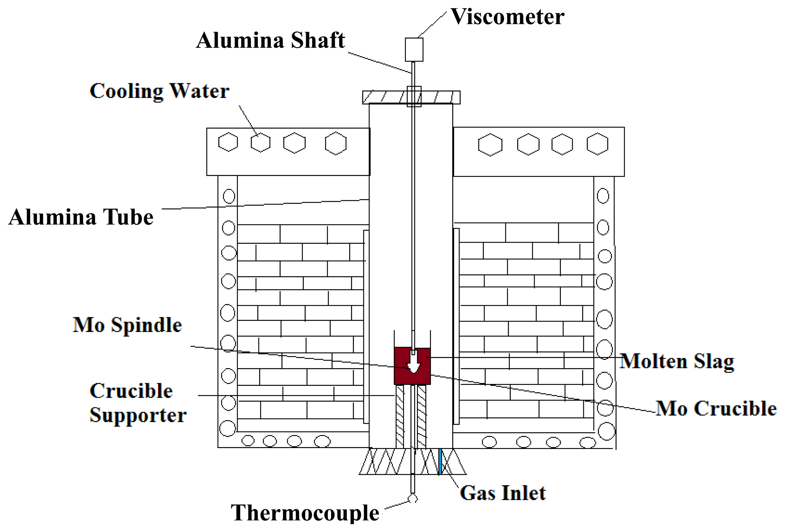
The viscosity measurements were carried out using a Brookfield digital viscometer and the experimental apparatus was as represented in Figure 1. The crucible and spindle used in the present experiments were made of molybdenum to prevent slag contamination. The viscosity was obtained by measuring the torque of the molybdenum spindle in the molybdenum crucible filled with liquid slag after a calibration experiment using standard oil of known viscosity to confirm the measurement accuracy. Viscosity measurements of the slag were carried out in a molybdenum crucible containing 140 g slag powder placed in the furnace and argon gas was flowed into the heating chamber at the rate of 0.3 NL/min to prevent the oxidation of the molybdenum crucible and spindle. Then the furnace was heated to 1650 °C at a heating rate of 5 °C/min and held for 2 hours to homogenize the slag temperature and chemical composition. After that, molybdenum spindle was carefully immersed into the liquid slag and then rotated to measure the viscosity. Three rotation rates were used for the viscosity measurement at a given temperature with an equilibration time of 30 min to stabilize the slag temperature in this study and the average value of these three measured viscosities was taken as the viscosity at the corresponding temperature. The cooling rate used between different temperatures was 5 °C/min. The FactSage software was used to calculate the liquidus temperature (TLQ) of the slag melts.
2.3. Laboratory Scale Experiment
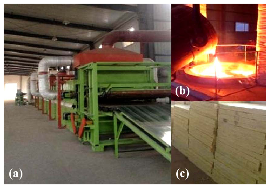
In order to simulate the slag wool fabrication process, a laboratory scale experimental setup was built as shown in Figure 2a, which was made up of induction furnace, high-speed nozzle, air tank, air compressor, fiber collector, etc. During the slag wool preparation experiment, 10 kg mixture of BF slag and CA were put into the induction furnace to be melted. The graphite crucible in the furnace was used as the induction heating element while platinum rhodium thermocouple was inserted into the furnace to measure the temperature. The induction furnace was heated up to 1650 °C and held for 30 min to homogenize the temperature and slag compositions. After that, the slag melt slowly flowed out from the slit at the bottom of the furnace. The height between the slit and the nozzle was controlled accordingly. The melt stream was then blown into fibers by a high-speed air jet under a controllable pressure ranging from 0.65 MPa to 1.25 MPa. An infrared thermodetector was used to monitor the temperature of the molten slag stream.
3. Results and Discussion
3.1. Laboratory Scale Experiment
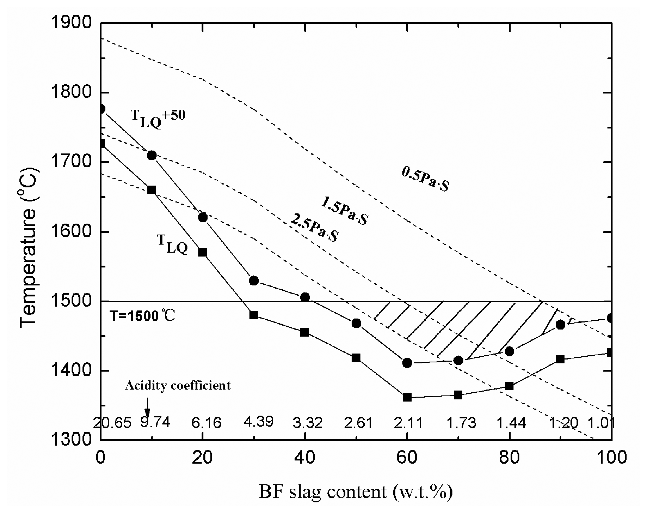
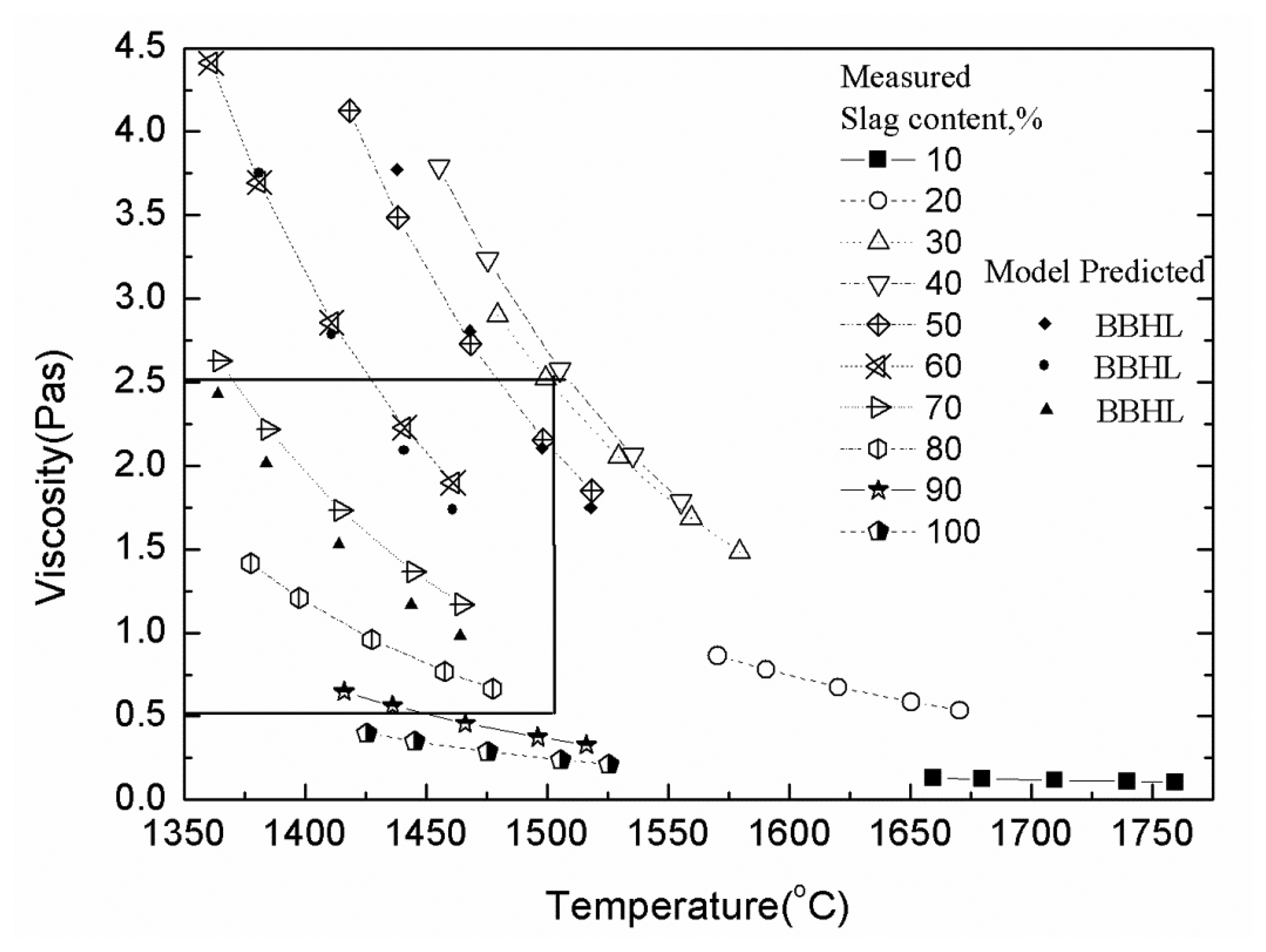
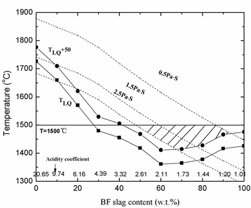
Viscosity and temperature of the slag melt were proved to be the determining factors in the preparation process. The slag viscosity of 0.5–2.5 Pa·s and the slag temperature of 50 °C higher than the liquidus temperature are generally thought to be suitable parameters for the slag wool production [16,17]. Therefore, to establish a suitable slag wool preparation process, the viscosity and liquidus temperature of the slag melts with different BF contents were studied and the results are shown in Figure 3 and Table 2. It can be seen that the liquidus temperature initially decreases and then increases slightly, while the viscosity of melts decreased with increasing BF slag contents. Considering the viscosity and liquidus temperature variations, an approximate range was therefore determined, which was labeled in the figure with oblique lines. As can be seen, the slag wool can be produced when the BF slag content varies from 50% to 90%. Figure 4 summarizes the viscosity variation versus temperature. The viscosities of MW05, MW06 and MW07 were also predicted by the BBHLW model [18] and labeled in Figure 4 for comparison, which confirms the accuracy of the measurements. It can be seen that the optimized temperature is in the range of 1371 °C to 1500 °C with a BF slag content from 90% to 50%. According to the actual industrial conditions, 1550 °C was chosen as the slag temperature for injection.
Based on the aforementioned findings, the slag fiber was produced using the experimental setup shown in Figure 2a. The filaments as well as the fragments with different BF slag contents were shown in Figure 5.
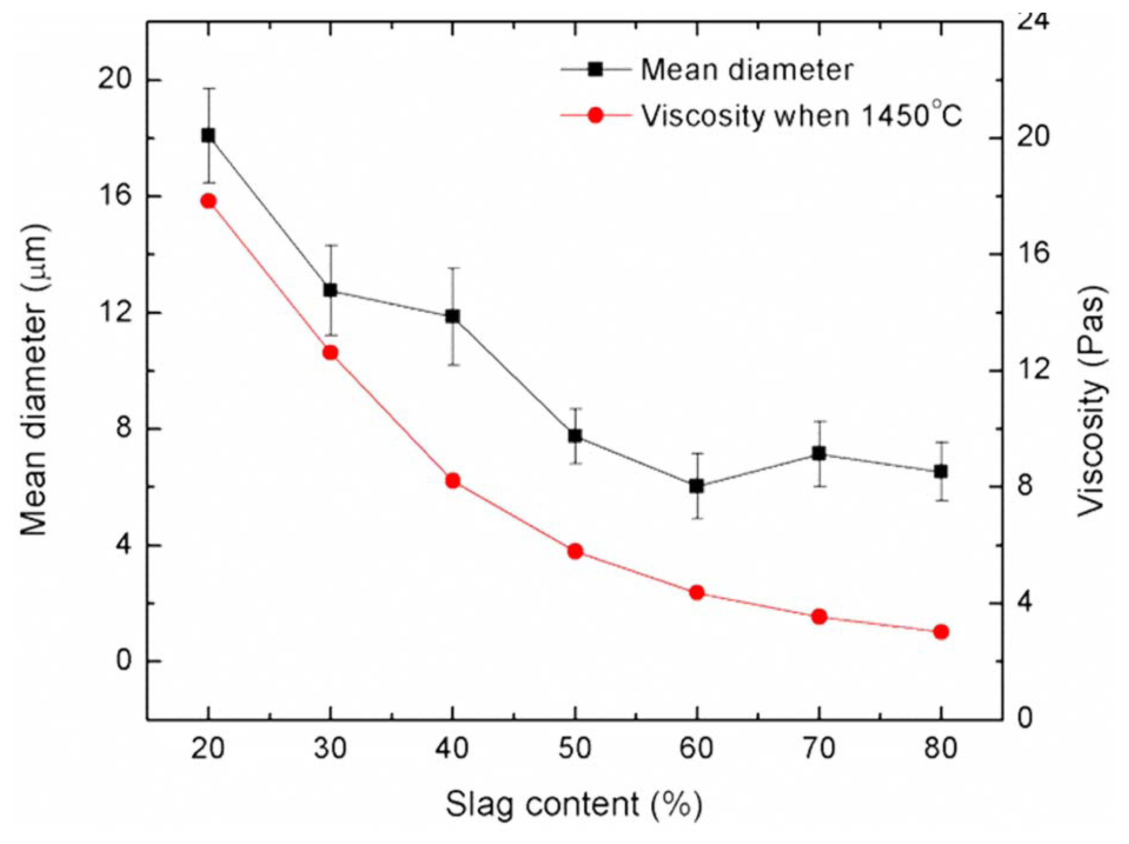
It is clear that the slag fibers can be fabricated when the BF slag content is in the range of 20%–80%, while only slag shots were produced when the slag content is above 80%. In each sample, 100 slag filaments were measured by microscope to calculate the mean diameters, and the results were shown in Figure 6. It can be observed that the mean diameter of slag fiber decreases from 18 μm to 5 μm as the BF slag content increases from 20% to 80%. According to the Chinese National Standard GB/T 11835-2004 [19], a fiber with diameter less than 7 μm is qualified. Thus, qualified slag fiber can be fabricated when the slag content is in the range of 60%–80%. The chemical composition of mixtures of BF slag and CA were further determined. It can be seen from Figure 6 that the viscosity of mixtures changes from 2.37 Pa·s to 1.02 Pa·s as the slag ratio increases from 60% to 80%, which is consistent with the aforementioned prediction.
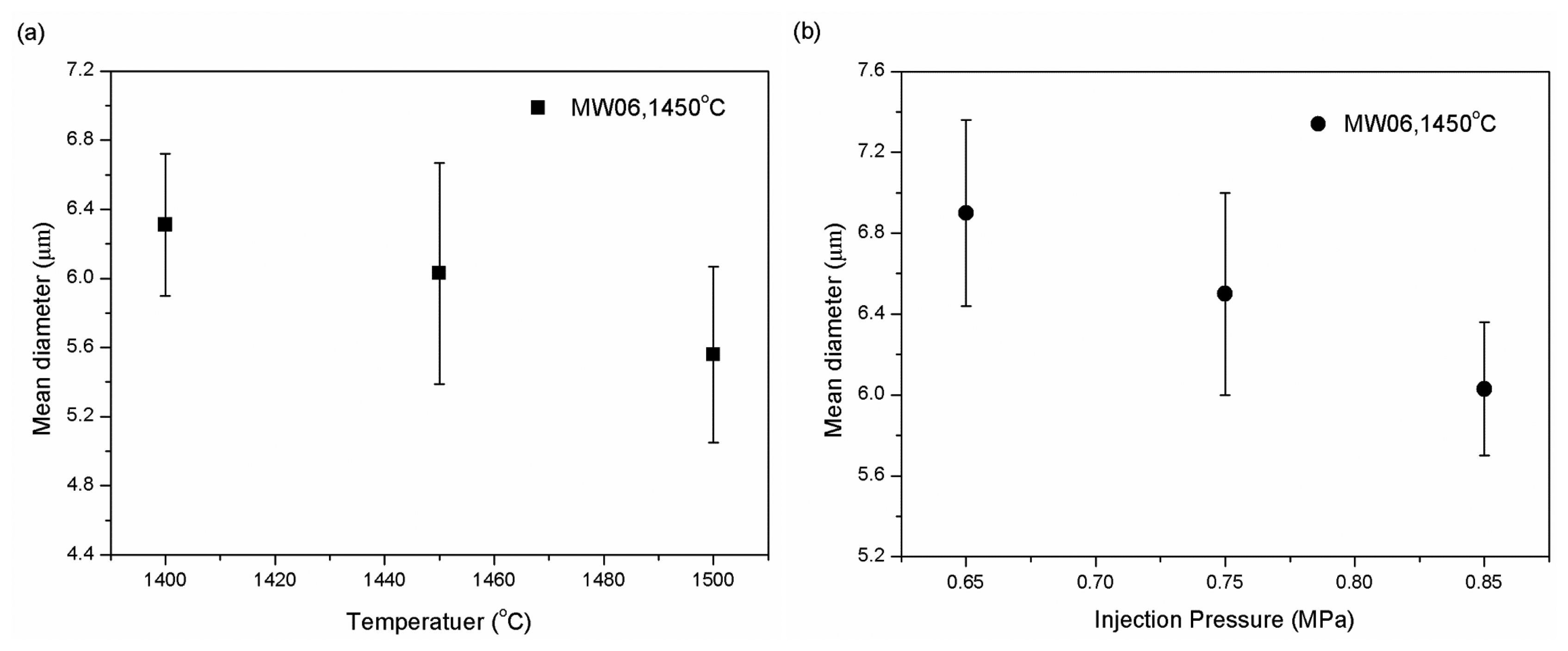
The injection temperature was further studied, and Figure 7a shows the change of mean diameter of slag fibers with temperature (MW06). The results indicate that the diameter decreases slightly from 6.31 μm to 5.56 μm as the temperature increases from 1500 °C to 1600 °C, i.e., the slag fiber can be fabricated with a relative wide injection temperature range from 1500 °C to 1600 °C. At a fixed injection slag temperature (1550 °C) and fixed BF slag content (60%), the effect of pressure on the mean diameter was studied, and the results are shown in Figure 7b. It can be included that the incremental of spraying air pressure from 0.65 MPa to 0.85 MPa results in an decrease of mean diameter from 6.91 μm to 6.03 μm, respectively, i.e., the slag fiber can be obtained in a wide pressure range [20].
Therefore, the parameters for producing the slag wool could be obtained as an injection temperature range of 1500 °C to 1600 °C, the pressure range of 0.65 MPa to 0.85 MPa, and a BF slag content range of 60%–80%. The laboratory experimental results are in agreement with the theoretical predictions. These findings provided the basic knowledge for the future industrial application.
3.2. Mechanical Property of the Slag Fiber
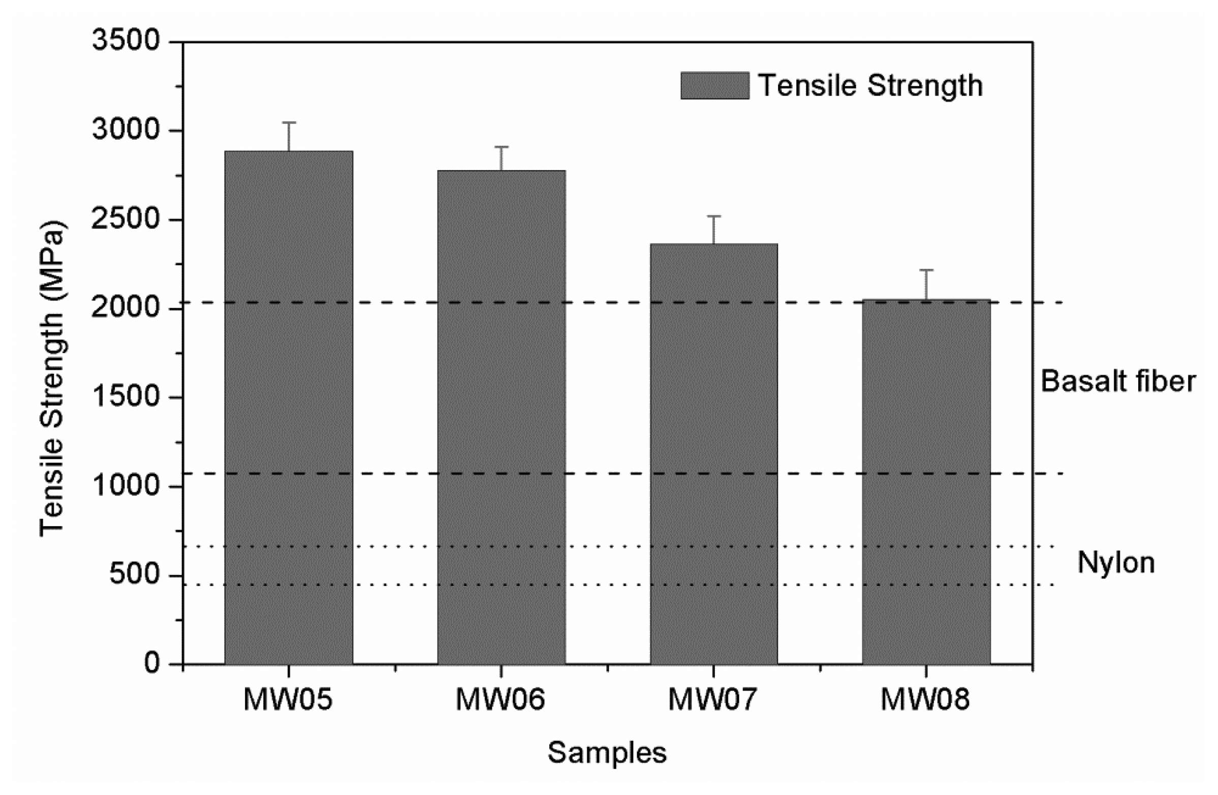
The mechanical and thermal properties of the obtained slag wools were investigated. A high precision short fiber tester JSF08 developed by Shanghai Powereach Co., Ltd. (Shanghai, China) was used for the mechanical property measurements. The mean tensile strength and elongation rate of the fibers for samples MW05, MW06, MW07, MW08 are shown in Figure 8. It can be seen that the slag fibers show excellent tensile strength properties, that decrease from 2886.63 MPa to 2053.22 MPa with decreasing Al2O3 content. For a comparison, the tensile strength of basalt fiber (1140–2020 MPa) [21] and nylon (490–680 MPa) were also included in the figure, which shows that tensile strength of the obtained slag wool fiber is higher than both organic and traditional mineral fibers.
3.3. Thermal Properties of the Slag Wool
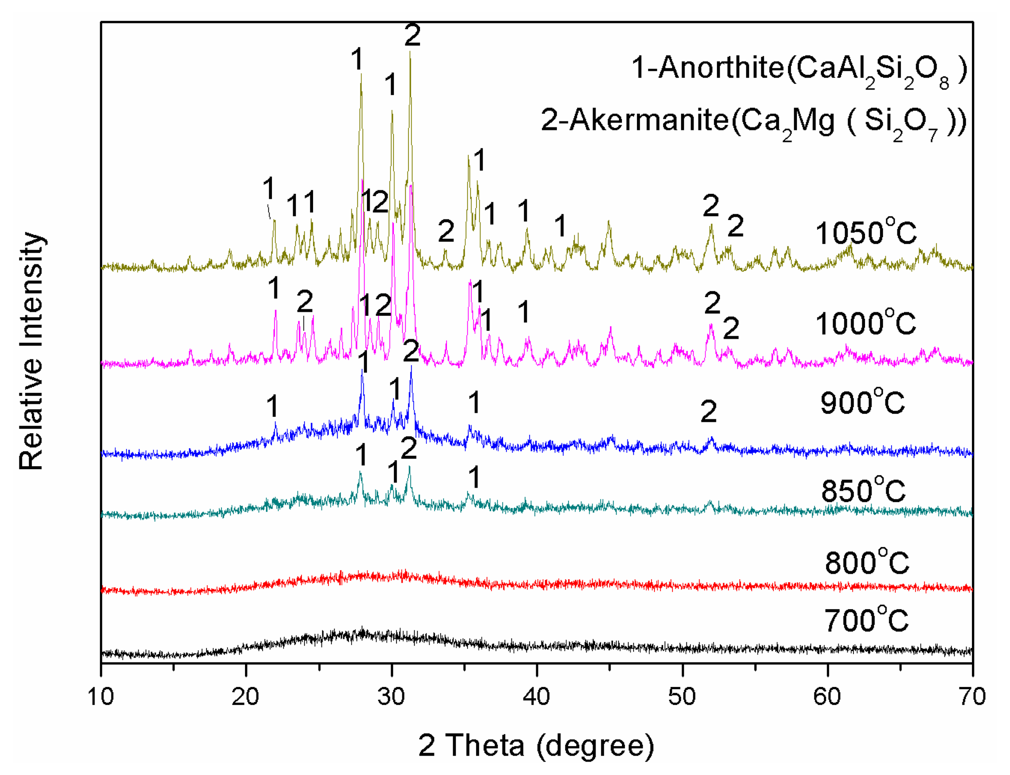
The thermal properties of the slag fiber were investigated and the results are shown in Figure 9. The results indicate that the glass transition temperature (Tg) of the slag fiber increases from 894 °C to 901 °C as the content of the BF slag decreases from 80% to 50%, respectively, i.e., the present slag wool can be used under the glass transition temperature. From the viewpoint of engineering applications, the glass transition temperature of the fiber is the upper limit in long-term use. The formation of crystals was also examined, and the results are shown in Figure 10. As it can be seen, no crystallization was observed when the temperature was lower than 850 °C, and calcium akermanite (Ca2MgSi2O7) and anorthite (CaAl2Si2O8) were precipitated as the temperature reached higher than 850 °C. This indicates that the maximum long term use temperature of slag wool products should not exceed 850 °C.
4. Industrial Application and Energy Consumption Analysis
4.1. Industrial Application
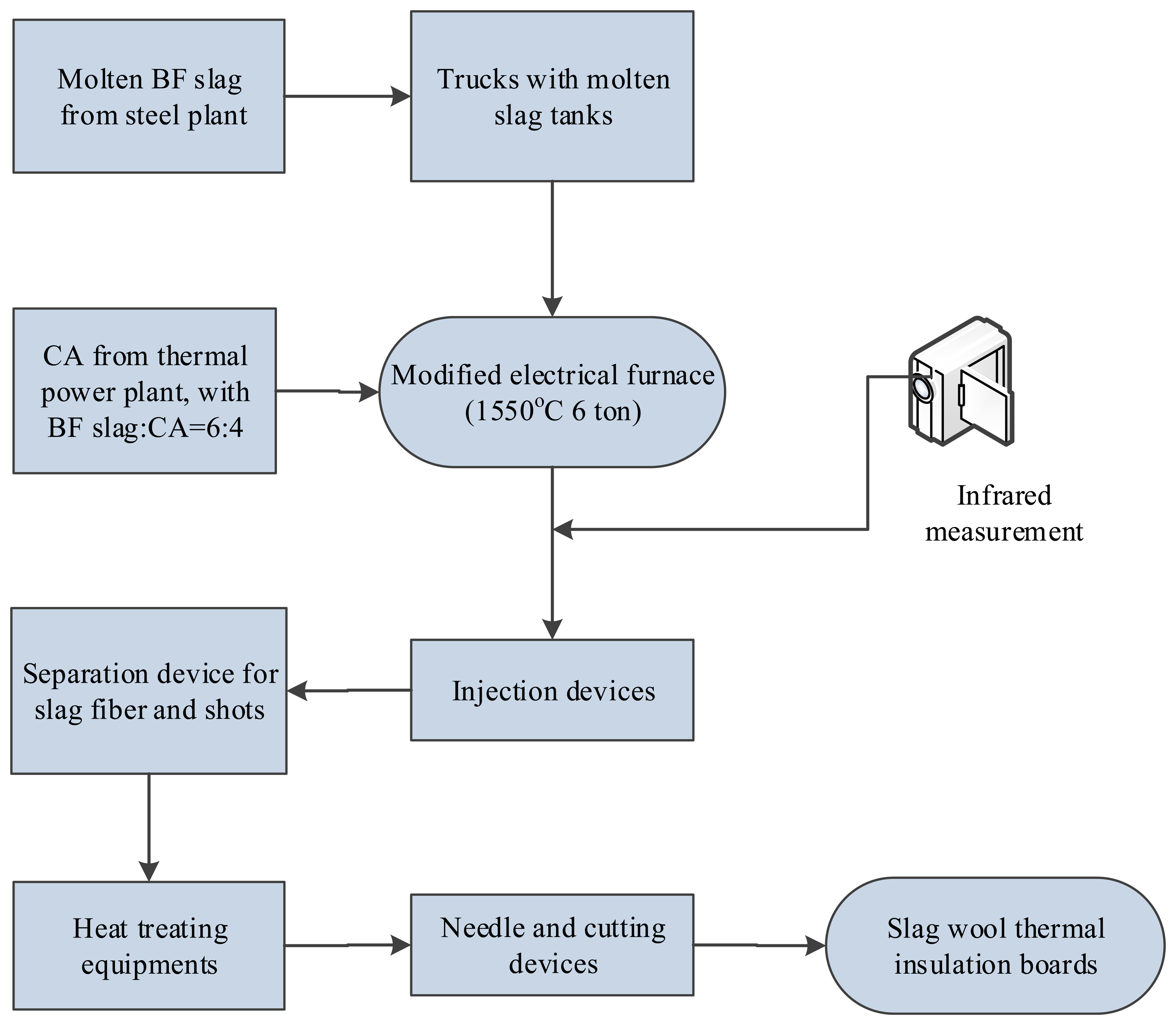
Based on the laboratory scale experiments, an industrial slag wool plant with annual output of 20,000 tons using high temperature BF slag and CA as raw materials has been constructed in Shanxi Province, China. Figure 11 shows a process flow diagram for preparing slag wool using these raw materials. Molten BF slag was picked up from a taphole and transported using a modified heavy truck with a slag tanker. Then, the molten BF slag was dumped into a modified electrical furnace, and the CA was also put into the electrical furnace to modify the melt. The electrical furnace kept the temperature at 1550 °C, and the melt stream was allowed to flow out. After high-speed injection blowing, slag wool with binders was sent onto a transmission track and further heated, needled and cut to make slag wool boards. The on-site preparation process illustration and equipment are shown in Figure 12.
4.2. Analysis of Energy Consumption
Energy consumption in the traditional slag wool industry consists of two parts, coal consumption and electricity consumption. For a cupola furnace with normal temperature raw material, coal is the major energy resource. To melt the raw materials at about 1550 °C, considerable heat is needed. Furthermore, the various mechanical devices used, including injection devices, separation devices, and heat treating equipment, also need electric power. However, for an electrical furnace with molten slag and coal ash as raw materials, electricity is the sole power source in the process. Plenty of energy is saved since high temperature ingredient technology is adopted. All the data in Table 3 are provided by the Shanxi Province slag wool plant, and measured in the industrial preparation tests. According to measurements and calculations of the plant, 1170.80 kWh (equivalent to 0.15 tons standard coal) is consumed to produce one ton of slag wool while 0.49 tons standard coal/ton is the average consumption for the traditional cupola method. Thus, for a plant with annual output of 20,000 tons, about 6800.00 tons standard coal could be saved and the energy consumption would be significantly reduced by 69.39%.
Coal burning during traditional cupola furnace process will produce large amounts of waste gases, which contain SO2 and NOx. Because of the large space required and high cost, desulphurization equipment is rarely used in slag wool plants. However, if electrical furnace without coal burning is employed, there will be almost no exhaust emissions from the process. In fact, the emissions could be transferred to the power plant where large and efficient desulphurization equipments have been built. According to the measurements in the industrial test, nearly no waste gas and very little smoke dust were produced with the new method reported in this paper. As shown in Table 3, the reduced exhaust emissions will reach 80 million cubic meters for a plant with an annual output of 20,000 tons. As for smoke dust, which is mainly composed of visible particles, the decrease should be 20 tons per year. Notably, the absolute quantity of smoke dust is only 9.1% of the traditional method, which will be of great benefit to improve the hazy weather problem in China. However, it should be mentioned that the transportation cost of large amounts of raw materials must be also considered. Therefore, any slag wool plant using the present method should be established near the material source with a corresponding “service radius”.
5. Conclusions
A novel method of slag wool preparation from molten BF slag and coal ash by a high-speed air injection method was investigated in the laboratory. The proper liquidus temperature and viscosity of the slag mixture for slag wool fabrication were experimentally studied and the relations of the properties of the slag wool and the process parameters were investigated. The optimized BF slag ratio with smallest mean diameter is 60% (MW06). The mean diameter decreases as the slag temperature increases or the air pressure increases.
The mean tensile strength of the fibers obtained in the laboratory is more than 2000 MPa. Meanwhile, the mean elongation rate is between 1.3% and 1.6%. Via DTA and XRD results, it can be concluded that the long-term use temperature of the wool should be under 850 °C.
Industrial application on a slag wool production line with an annual capacity of 20,000 tons shows that the novel method could be applied to continuous industrial production. Compared with the traditional cupola method, energy consumption for producing a ton of slag wool could save 346.3 kg coal equivalent due to its sensible heat. Moreover, a 90% pollution emission reduction is also obtained.
Compared with traditional methods, the present method can recover both the wasted material resources and wasted energy resources at the same time, which has great significance and prospects.
Acknowledgments
The authors gratefully acknowledge the financial support by the Common Development Fund of Beijing and the National Natural Science Foundation of China (51172003 and 51172001). Supports by the National High Technology Research and Development Program of China (863 Program, 2012AA06A114) and Key Projects in the National Science & Technology Pillar Program (2011BAB03B02 and 2011BAB02B05) are also acknowledged.
Conflicts of Interest
The authors declare no conflict of interest.
References
- Papadopoulos, A.M. State of the art in thermal insulation materials and aims for future developments. Energy Build. 2005, 37, 77–86. [Google Scholar]
- Ji, R.; Zhang, Z.T.; Liu, L.L.; Wang, X.D. Numerical modeling and experimental study of heat transfer in ceramic fiberboard. Text. Res. J. 2013. Available online: http://trj.sagepub.com/content/early/2013/11/26/0040517513485630.abstract (accessed on 5 December 2013). [Google Scholar] [CrossRef]
- Wang, J.Q.; Du, J.X.; Zhu, J.; Wilkie, A.C. An XPS study of the thermal degradation and flame retardant mechanism of polystyrene-clay nanocomposites. Polym. Degrad. Stab. 2002, 77, 249–252. [Google Scholar]
- Liu, B.Y.; Zhang, X.B. Feasibility of producing basalt wool by blast furnace molten slag. Multipurp. Util. Miner. Resour. 2006, 1, 44–46. [Google Scholar]
- Leth-Miller, R.; Jensen, A.D.; Glarborg, P.; Jensen, L.M.; Hansen, P.B.; Jorgensen, S.B. Investigation of a Mineral Melting Cupola Furnace. Part I. Experimental Work. Ind. Eng. Chem. Res. 2003, 42, 6872–6879. [Google Scholar]
- Yang, H. Efficient utilization of blast furnace slag sensible heat. Energy Conserv. Environ. Prot. 2003, 2, 34–35. [Google Scholar]
- Wu, D.; Deng, X.J.; Bi, X.Y.; Li, F.; Tan, H.B.; Liao, G.L. Study on the Visibility Reduction Caused by Atmospheric Haze in Guangzhou Area. J. Trop. Meteorol. 2007, 13, 77–80. [Google Scholar]
- Blagojevic, B.; Sirok, B.; Hocevar, M. Cooling of the Fibers in Mineral Wool Produced by A Double-Disc Spining Machine. Ceramics Silikáty 2009, 53, 25–30. [Google Scholar]
- Bajcar, T.; Blagojevic, B.; Sirok, B.; Dular, M. Influence of flow properties on a structure of a mineral wool primary layer. Exp. Therm. Fluid Sci. 2007, 32, 440–449. [Google Scholar]
- Cheng, A.; Lin, W.T.; Huang, R. Application of rock wool waste in cement-based composites. Mater. Des. 2011, 32, 636–642. [Google Scholar]
- Barati, M.; Esfahani, S.; Utigard, T.A. Energy recovery from high temperature slags. Energy 2011, 36, 5440–5449. [Google Scholar]
- Xie, D.; Jahanshahi, S. Waste heat recovery from molten slags. Proceedings of the 4th International Congress on Science and Technology of Steelmaking, Gifu, Japan, 6–8 October 2008; pp. 674–677.
- Xie, D.; Jahanshahi, S.; Norgate, T. Dry granulation to provide a sustainable option for slag treatment. Proceedings of the Sustainable Mining Conference, Kalgoorlie, Australia, 17–19 August 2010; pp. 22–28.
- Fruehan, R.J.; Fortini, O.; Paxton, H.W.; Brindle, R. Theoretical Minimum Energies to Produce Steel for Selected Conditions; Technical Report for the U.S. Department of Energy, Office of Industrial Technologies; Carnegie Mellon University: Pittsburgh, PA, USA; March; 2000. [Google Scholar]
- Bisio, G. Energy Recovery from Molten Slag and Exploitation of the Recovered Energy. Energy 1997, 22, 501–509. [Google Scholar]
- Zhang, Y.M. Glass Fiber and Mineral Wool Encyclopedia, 1st ed.; Chemical Industry Press: Beijing, China, 2001; pp. 79–82. [Google Scholar]
- Yang, H. Technology improvement for production of mineral wool with thermal power plant liquid cyclone furnace slag. Insul. Mater. Build. Energy Sav. 2004, 7, 37–39, In Chinese. [Google Scholar]
- Duchesne, M.A.; Bronsch, A.M.; Hughes, R.W.; Masset, P.J. Slag Viscosity Modeling Toolbox. Fuel 2013, 114, 38–43. [Google Scholar]
- Chinese National Standard GB/T 11835-2007. Available online: http://doc.csres.com/showdoc-43067.html (accessed on 22 June 2007).
- Novitskii, A.G.; Efremov, M.V. A study of the fiber blowing process in the production of mineral wool. Refract. Ind. Ceram. 2006, 47, 121–124. [Google Scholar]
- Militky, J.; Kovacic, V. Ultimate Mechanical Properties of Basalt Filaments. Text. Res. J. 1996, 66, 225–229. [Google Scholar]


| Sample | BF Slag | Coal Ash | CaO | SiO2 | Al2O3 | MgO | Na2O | K2O | Fe2O3 | TiO2 | MnO | P2O5 |
|---|---|---|---|---|---|---|---|---|---|---|---|---|
| MW10 | 100 | 0 | 39.93 | 32.52 | 15.95 | 8.86 | 0.32 | 0.44 | 0.58 | 1.21 | 0.18 | 0.00 |
| MW09 | 90 | 10 | 34.21 | 33.71 | 19.70 | 7.61 | 0.30 | 0.54 | 0.73 | 1.26 | 0.16 | 0.06 |
| MW08 | 80 | 20 | 29.10 | 35.21 | 23.30 | 6.36 | 0.31 | 0.63 | 1.18 | 1.28 | 0.14 | 0.09 |
| MW07 | 70 | 30 | 28.92 | 34.62 | 24.23 | 6.04 | 0.35 | 0.62 | 1.25 | 1.38 | 0.14 | 0.12 |
| MW06 | 60 | 40 | 25.34 | 36.13 | 26.66 | 5.32 | 0.37 | 0.65 | 1.46 | 1.39 | 0.13 | 0.17 |
| MW05 | 50 | 50 | 21.45 | 37.59 | 29.21 | 4.70 | 0.37 | 0.73 | 1.71 | 1.47 | 0.11 | 0.20 |
| MW04 | 40 | 60 | 18.72 | 39.89 | 32.06 | 4.06 | 0.39 | 0.80 | 2.19 | 1.55 | 0.11 | 0.24 |
| MW03 | 30 | 70 | 14.78 | 40.77 | 34.35 | 3.19 | 0.42 | 0.84 | 2.49 | 1.57 | 0.09 | 0.28 |
| MW02 | 20 | 80 | 11.40 | 42.87 | 35.44 | 2.45 | 0.45 | 0.91 | 2.60 | 1.64 | 0.08 | 0.32 |
| MW01 | 10 | 90 | 7.10 | 43.73 | 38.16 | 1.41 | 0.45 | 0.98 | 2.97 | 1.69 | 0.06 | 0.50 |
| MW00 | 0 | 100 | 3.57 | 45.00 | 40.61 | 0.58 | 0.46 | 1.04 | 3.26 | 1.75 | 0.05 | 0.55 |
| Sample | BF Slag content | Acidity coefficient Mk | TLQ (°C) | 1550 °C Viscosity (Pa·S) | 1.5 Pa·S Temperature (°C) |
|---|---|---|---|---|---|
| MW10 | 100% | 1.01 | 1425.5 | 0.48 | 1336 |
| MW09 | 90% | 1.20 | 1416.2 | 0.69 | 1373 |
| MW08 | 80% | 1.44 | 1377.7 | 1.02 | 1412 |
| MW07 | 70% | 1.73 | 1364.8 | 1.54 | 1452 |
| MW06 | 60% | 2.11 | 1361.1 | 2.37 | 1496 |
| MW05 | 50% | 2.61 | 1418.4 | 3.78 | 1542 |
| MW04 | 40% | 3.32 | 1455.3 | 6.21 | 1592 |
| MW03 | 30% | 4.39 | 1479.5 | 10.62 | 1645 |
| MW02 | 20% | 6.16 | 1570.4 | 15.84 | 1685 |
| MW01 | 10% | 9.74 | 1659.7 | 20.98 | 1713 |
| MW00 | 0% | 20.65 | 1726.6 | 28.04 | 1742 |
| (a) Cupola furnace method | (b) Electrical furnace with molten slag method | |
|---|---|---|
| Coal consumption (ton/ton slag wool) | 0.45 | 0.00 |
| Electricity consumption (kWh/ton) | 325.20 | 1170.80 |
| Total consumption (t standard coal/ton slag wool) | 0.49 | 0.15 |
| Annual consumption (t standard coal) | 9800.00 | 3000.00 |
| Comparison of pollutant generation | ||
| Waste gas (m3/ton) | 4000.00 | 0.00 |
| Smoke dust (kg/ton) | 1.10 | 0.10 |
© 2014 by the authors; licensee MDPI, Basel, Switzerland. This article is an open access article distributed under the terms and conditions of the Creative Commons Attribution license ( http://creativecommons.org/licenses/by/3.0/).
Share and Cite
Zhao, D.; Zhang, Z.; Tang, X.; Liu, L.; Wang, X. Preparation of Slag Wool by Integrated Waste-Heat Recovery and Resource Recycling of Molten Blast Furnace Slags: From Fundamental to Industrial Application. Energies 2014, 7, 3121-3135. https://doi.org/10.3390/en7053121
Zhao D, Zhang Z, Tang X, Liu L, Wang X. Preparation of Slag Wool by Integrated Waste-Heat Recovery and Resource Recycling of Molten Blast Furnace Slags: From Fundamental to Industrial Application. Energies. 2014; 7(5):3121-3135. https://doi.org/10.3390/en7053121
Chicago/Turabian StyleZhao, Dawei, Zuotai Zhang, Xulong Tang, Lili Liu, and Xidong Wang. 2014. "Preparation of Slag Wool by Integrated Waste-Heat Recovery and Resource Recycling of Molten Blast Furnace Slags: From Fundamental to Industrial Application" Energies 7, no. 5: 3121-3135. https://doi.org/10.3390/en7053121