A Review on Cold Start of Proton Exchange Membrane Fuel Cells

Abstract
: Successful and rapid startup of proton exchange membrane fuel cells (PEMFCs) at subfreezing temperatures (also called cold start) is of great importance for their commercialization in automotive and portable devices. In order to maintain good proton conductivity, the water content in the membrane must be kept at a certain level to ensure that the membrane remains fully hydrated. However, the water in the pores of the catalyst layer (CL), gas diffusion layer (GDL) and the membrane may freeze once the cell temperature decreases below the freezing point (Tf). Thus, methods which could enable the fuel cell startup without or with slight performance degradation at subfreezing temperature need to be studied. This paper presents an extensive review on cold start of PEMFCs, including the state and phase changes of water in PEMFCs, impacts of water freezing on PEMFCs, numerical and experimental studies on PEMFCs, and cold start strategies. The impacts on each component of the fuel cell are discussed in detail. Related numerical and experimental work is also discussed. It should be mentioned that the cold start strategies, especially the enumerated patents, are of great reference value on the practical cold start process.1. Introduction
A fuel cell is a device that converts the chemical energy from a fuel into electricity through a chemical reaction with oxygen or another oxidizing agent. Typically, a fuel cell has positive and negative electrodes and electrolytes, like a battery; yet, in fact it cannot “store power” but functions as a “power plant.” A proton exchange membrane fuel cell (PEMFC) takes a proton exchange membrane (PEM, also known as polymer electrolyte membrane) as electrolyte and represents the most common type of fuel cells. It's more and more widely used because of its capability in low temperature operation, high power density, relatively high efficiency and zero/low emission [1–5].
A PEMFC mainly consists of membrane, electrode, gas diffusion layer (GDL) and bipolar plates. The operation of the hydrogen PEMFC is extremely simple. The first demonstration of a fuel cell was designed and implemented by lawyer and scientist William Grove in 1839. In the anode, hydrogen flows to the catalyst layer (CL) through the GDL, while in the cathode, oxygen or air flows to the CL through the GDL simultaneously when a PEMFC works. Reactive gas smoothly reaches the electrode reaction interface coated with catalyst after passing through the GDL.
On the anode side, two protons and two electrons are produced when hydrogen is split by ionization:
This reaction releases energy. On the cathode side, an oxygen reduction reaction occurs. Water is produced in this reaction:
In this process, protons diffuse though the PEM to the cathode side while the electrons travel to the cathode through the external circuit. As a result, electricity is generated.
In summary, the overall reaction in PEMFC is that hydrogen reacts with oxygen, and at the same time water, electrical energy and waste heat is produced:
For a single cell, the reversible voltage (without any loss) can be calculated from reversible open circuit voltage equation:
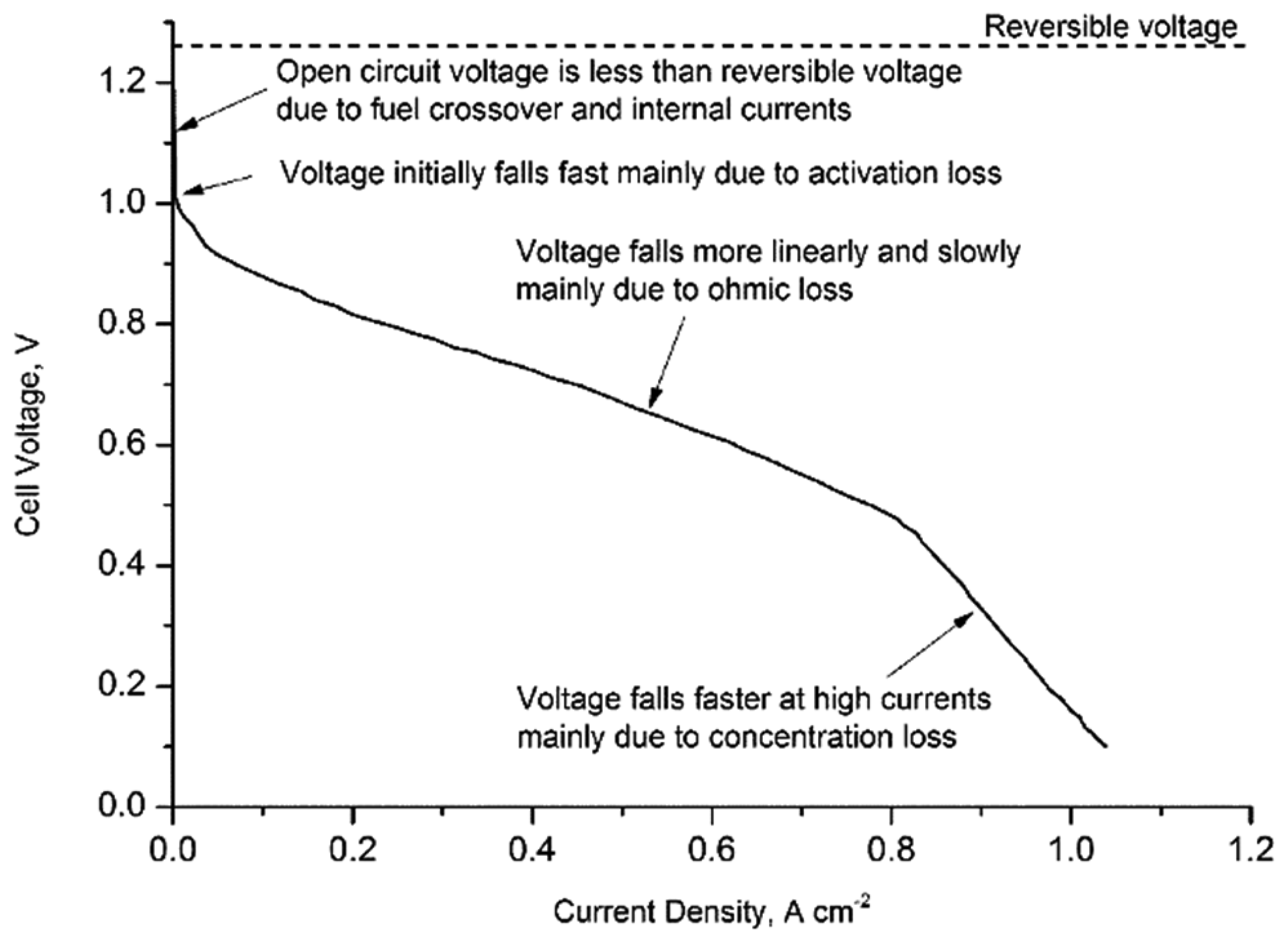
According to Equation (4), the reversible voltage for a PEMFC operating below 80 °C is about 1.18 V. However, in practice, the voltage is much lower than this theoretical value. The voltage drop is caused by fuel cell irreversibility, i.e., activation losses, fuel crossover and internal currents, ohmic losses and mass transport or concentration losses (Figure 1). Activation losses are caused by the slowness of the reactions taking place on the surface of the electrodes and this voltage drop is highly non-linear. Fuel crossover and internal currents, which result from the waste of fuel passing through the electrolyte and electron conduction through the electrolyte, can be ignored for PEMFC. Ohmic losses are the resistances due to the flow of electrons through the electrodes and the various interconnections, as well as the flow of ions through the electrolyte. Mass transport or concentration losses are mainly caused by the change of concentration of the reactants at the surface of the electrodes. Therefore, the operating voltage can be calculated from Equation (5):
2. States and Phase Changes of Water in PEMFCs
As the PEM should be well hydrated to achieve high proton conductivity and electrochemical reactions produce water, different states of water always coexist in PEMFCs. Much attention has been paid to the state of water in PEMFC both in experimental and theoretical researches. Markötter et al. [8] applied quasi in-situ neutron tomography to analyze the water distribution in operating fuel cells. In this research, when the water distribution is analyzed after the fuel cells are switched-off for 36 h, it's showed that the water content gradually increased. Water in PEMFC can be present in the state of vapor, liquid and ice during various phase change processes in different media and operating conditions. On the whole, the water in PEMFC can be divided into four states: non-frozen water, liquid water, vapor and ice [7].
In a membrane, water content λ, which is often applied to represent the water absorption level of the membrane, is defined as the number of water molecules per SO3−:
Jiao et al. [10] introduced the classifications of non-frozen water and frozen water to describe the state of water in membrane on the basis of the observations of the freezing behavior of water. The water freezing was also studied by Thompson et al. [11], Cappadonia et al. [12,13], Yoshida et al. [14], and Pineriet al. [15] using differential scanning calorimetry (DSC) and nuclear magnetic resonance (NMR). In reference [16], the amounts of the different types of water were also determined with DSC. The results indicated that water does not freeze unless the water content λ is higher than 4.8. A more detailed classification of non-frozen water into non-freezable, freezable and free water was given in references [17–19] on the basis of bonding strengthen between water molecules and the sulphuric acid (H+SO3−). If the water content is no more than 4.8, it may be called non-freezable water as it is tightly bound to H+SO3− [14]. If the water molecular is loosely bound to H+SO3−, it may exhibit freezing point depressions, and the free water will appear when the water content is relatively high. According to Eikerling et al. [20] and Roudgar et al. [21], water can also be sorted into surface water and bulk water. Surface water is tightly bound to H+SO3− and bulk water is regarded as liquid which is loosely bound to H+SO3−. As one can see from above, although there are different classification methods for water molecules in PEM, these methods are essentially the same. Table 1 shows freezing temperatures for different membrane water contents.
In a PEMFC, slow diffusion in the GDL may induce oxygen depletion. Bultel et al. [22] reported an investigation on mass transport in GDL of a PEMFC, and drew the conclusion that slow oxygen diffusion in the diffusion layer is a major concern, especially in non-optimized diffusion layers. In the GDL, water in the pores can be in the state of vapor, liquid and ice. At subfreezing temperatures, formation of liquid water can be neglected. Therefore, water in the pores of GDL can be simply regarded as vapor and ice. However, it should be noticed that when the local cell temperature increases beyond the Tf point of water, the ice would melt into liquid water.
Due to the differences of local temperature (Tlocal) and Tf, as well as vapor pressure and water saturation pressure, phase changes among different states of water in GDL may occur. The liquid water and vapor will convert into each other when Tlocal is higher than Tf with the existence of liquid water or vapor. If the vapor pressure is lower than the saturation pressure (Psat), liquid will evaporate to form vapor, and otherwise vapor will condense into liquid. The phase change between ice and vapor arises when Tlocal is lower than Tf, then vapor will desublimate into ice when the vapor pressure is higher than Psat, but the reverse won't happen under the operating conditions in PEMFCs [7].
Alink et al. [33] developed a numerical model to study the liquid water transport in the GDL for PEMFCs with water path networks. Pasaogullari et al. [34,35] studied the transport of liquid water in both hydrophilic and hydrophobic diffusion media in GDL with a one-dimensional analytical model and drew the conclusion that capillary transport is the dominant transport process to remove water from flooded GDLs. Pasaogullari et al. [35] developed a two-phase transport analytical model for further research where the effects of the micro-porous layer (MPL) and its properties on water transport in GDL are analyzed. It was found that the reduced water flux toward the cathode decreases cathode flooding. Therefore, the cell performance can be improved by relaxing the mass transfer limitations.
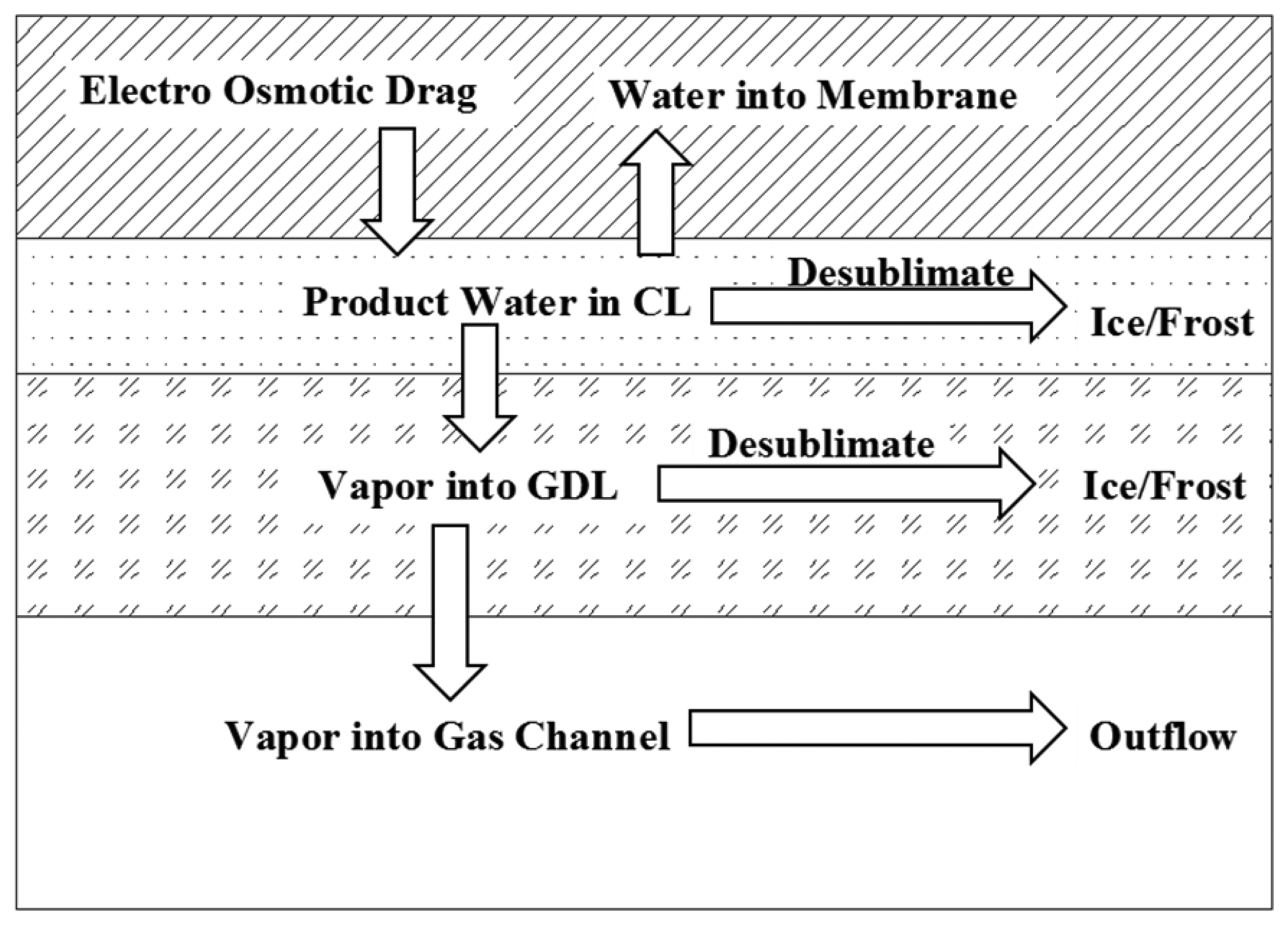
The CLs are the most important part of PEMFCs and a successful cold start process depends on the rapidly heating up of the CL. The state of water and phase change in CL might be much more complex as the CL consists of carbon and platinum particles and is connected with the PEM and GDL. Chan et al. [36] presented a transient model for fuel cell cathode-water transport inside a cathode. This model included the material conservation of oxygen, vapor, water inside the GDL and MPL, and the electrode kinetics in the CL. In the CL, liquid water, non-frozen water and ice can coexist under different conditions at different positions. The states of water in the CL are similar to those in the GDL and PEM in a sense. Specifically, the states of water in the pores of CL are the same as those in the pores of GDL, and the states in the ionomer of CL are similar to those in the ionomer of PEM [7]. The transportation of water inside the fuel cell during the cold start process is shown in Figure 2.
In the CL, the liquid water and vapor can be absorbed when the local pressure is lower than Psat of water under the temperature of the cell, as is at the interface between the CL and membrane, and vice versa. The non-frozen water, liquid water or vapor can freeze or desublimate to ice when Tlocal is lower than Tf and local pressure is lower or higher than Psat. The saturation water content can be calculated with the following equation [11]:
It should be mentioned that Tf of water could be decreased by the enhancement of the surface dynamics of water with the presence of small pores in CL. Equation (9) is often used to determine the vapor/liquid water conversion direction [38]:
In the flow channel, the state of water is relatively simple. Since the ice is formed in CL and GDL is immobile, the ice fraction in the flow channel can be neglected as it is much lower than that in CL and GDL. Therefore, there is only vapor and liquid water in the flow channel and they can transform mutually. If the supply in the cold start process is non-humidified gases, liquid water can also be neglected for its very low fraction. In addition, the gravity effect can also significantly affect the water phase change, as well as the performance of PEMFCs [39]. As a conclusion, the states of water in different parts of a PEMFC are summarized in Table 2.
3. Impacts of Water Freezing on PEMFCs
It has been experimentally determined that water freezing at subfreezing temperatures is the main reason for the difficulty or failure of the startup. In addition, repeated freeze/thaw (F/T) cycles would lead to the irreversible performance decay and device damage. As is well known the densities of water and ice at 0 °C are 999.8 kg/m3 and 916.8 kg/m3, respectively, and there is about a 9% volume expansion when water freezes at this temperature. As a result, water freezing will definitely generate unbalanced stresses in fuel cell and the stress disappears when the volume gets smaller with the melting of ice. The repeated generation and disappearance of the unbalanced stress in the fuel cell with the phase change of ice will cause damage on the structure and performance of the components to some extent. For further investigation, the damage is classified into three parts: impact on membrane, impact on catalyst coated membrane, and impact on membrane electrode assembly (MEA).
3.1. Impact on PEM
The PEM is one of the most important components in PEMFCs and the PEM properties can directly affect the fuel cell performance. The most widely used PEM in PEMFCs nowadays is sulfonated fluoroethylene (also called perfluorosulphonic acid polytetrafluoroethylene (PTFE) copolymer or Nafion®). In order to achieve a high performance, the sulfonated fluoroethylene membrane should be well hydrated [40]. Hence, when the ambient temperature decreases below Tf, the existence of ice may have a significant impact on the membrane.
The major factor influencing the performance and durability of PEMFCs is the water management, as methodically reviewed by Ji et al. [41]. Early in 1995, Wilson et al. [42] conducted F/T cycling experiment to verify the life of CL and the stability of the interface between the CL and the membrane of the platinum electrode. But only three F/T experiments were performed and no conspicuous performance degradation was observed. Cho et al. [43–45] claimed that whether it is dry (water content less than 3%) or wet, the proton conductivity changed slightly between 0.0319 S/cm and 0.0323 S/cm after F/T cycling during −10 °C to 30 °C. In addition, Cho et al. [44] performed a detailed and systematic study of the impact of water freezing on the performance of fuel cell with F/T cycling experiment. Oszcipok et al. [46] and Reiser et al. [47] investigated the cold start behavior of a single cell under isothermal constant voltage conditions by electrochemical impedance spectroscopy and cyclic voltammetry method. It turned out that the contact electrical resistance of the membrane increased at a rate of 5.4% per cold start and the electrochemical active surface area decreased at a rate of 2.4% per cold start. It was microscopically observed that the cathode diffusion layer and CL structure changed. The hydrophobicity of the membrane also deteriorated. These changes will inevitably lead to loss of fuel cell performance. Tajiri et al. [48] conducted an experiment at −30 °C. Certain measures were taken to maintain the stack temperature at a constant value and the electrical conductivity of the bipolar plate was measured for different inlet humidification conditions, which showed that humidification had a great effect on the electrical conductivity in a low temperature environment. This is because the area covered by ice formed in the GDL varies with humidification.
In order to investigate the impacts of ice on the membrane, McDonald et al. [49] conducted a study to figure out the physical and chemical changes in the membranes resulted from F/T cycling in 2003. As the membrane is fixed in the atmospheric environment, the water content of membrane is approximately 1.6%–3.4% (wt %). In this study, one set of Nafion® 112 is fixed only in the XY direction and the other set is fully fixed and the F/T cycling experiment is conducted from −40 °C to 80 °C. The results indicated that the freezing of water did not give rise to catastrophic damage to the membrane. Furthermore, it's concluded from the decreases in anisotropy of tensile strength and water swelling behavior of the membrane, together with lower oxygen permeability that a rearrangement in the ionomer at the molecular level is caused by the F/T cycling. Another set of experiments was conducted from −20 °C to room temperature, and it was shown that several cracks occurred in the PEM after F/T cycling. The cracks may be caused by the unbalanced stress due to the freezing of water in the membrane. The freezing of water in the membrane may also affect both the proton conductivity and electrical conductivity.
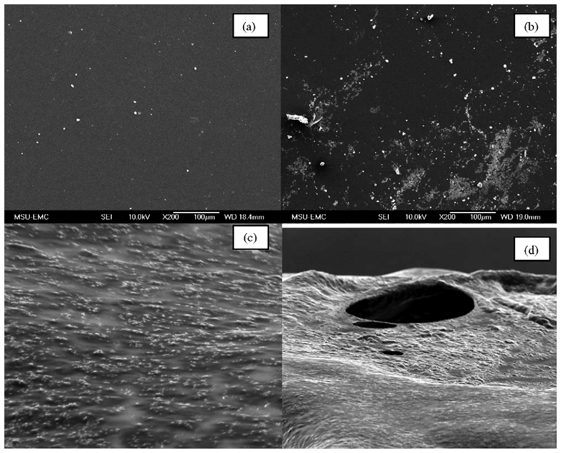
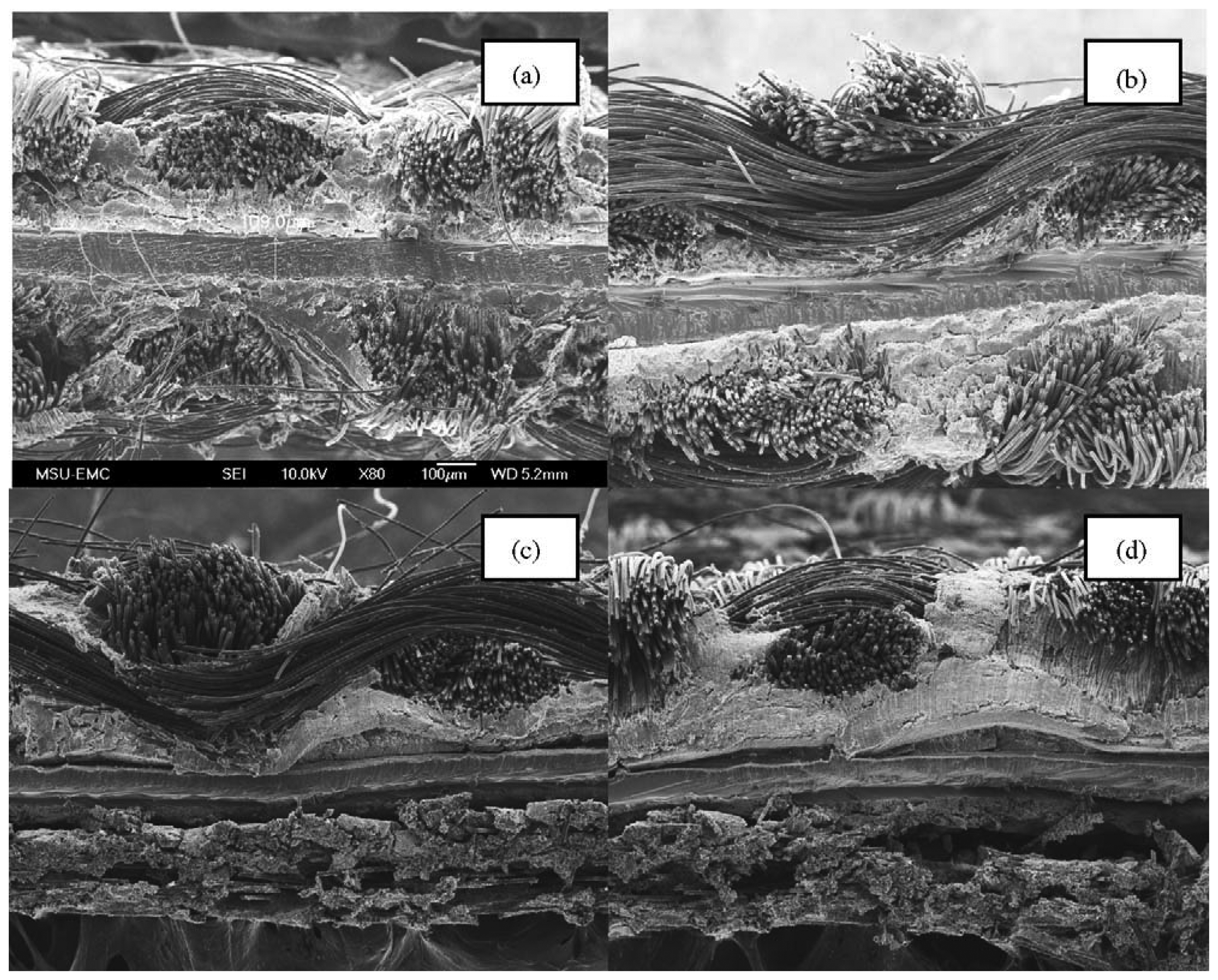
Yan et al. [50] studied the cold start behavior and the effects of subfreezing temperature on fuel cell performance using a 25 cm2 PEMFC. Four groups of experiments were taken respectively with the temperature of room temperature, −10 °C, −15 °C, as well as fresh membrane. Figure 3 shows the damage to the membrane. In the low magnification image, it can be observed that the membrane is fairly rough after exposure to sub-zero freezing (Figure 3c). In the high magnification image (Figure 3d), signs of pinhole damage appear in the membrane after operation at subfreezing temperatures.
3.2. Impact on MEA
The MEA consists of hydrogen electrode, oxygen electrode and PEM with two interfaces, i.e., hydrogen electrode/PEM interface and oxygen electrode/PEM interface. The effects of F/T cycling process on MEA properties also attracted much attention in recent years.
Mukundan et al. [51] conducted an experimental analysis to study the ice formation in PEMFCs at subfreezing temperatures with a neutron imaging method. The effect of MEA and GDL structure on the performance of PEMFCs operated isothermally at subfreezing temperatures was presented. McDonald et al. [49] measured the size, stability, tensile strength, equivalent EW value (the sum of the membrane and the CL) of the MEA, as well as the resistance (Ω cm−2) of the MEA at different relative humidity before and after F/T cycling.
Since the ion conductivity between the membrane and catalyst is low, the interface between the membrane and CL has attracted more and more attention. After a long time of operation, the interfaces will change significantly and the cathode CL will also be dissociated seriously [52]. However, there is no relevant report on whether water freezing will accelerate this degradation. The resistance can be analyzed by measuring the resistance of MEA and membrane by AC impedance method instead of directly measuring the resistance of fuel cell and membrane [43–45,53]. In another report, Cho et al. [44] studied the effect of thermal cycle between 80 °C and −10 °C with a hydrated PEM. They found that cell performance degraded drastically after only four cycles and other characteristics of MEA, such as pore size distribution and active surface area of the CL, were also altered. In a subsequent study, Cho et al. [45] observed that purging the cell with dry gas or filling the cell compartments with an antifreeze solution before the cell temperature drops below 0 °C can prevent MEA degradation. Degradation in electrochemical reaction at subzero temperatures was provided by Mao et al. [54]. In addition, as CL is directly in contact with the membrane, the formed prominent ice crystals at subfreezing temperature would pierce the PEM, resulting in perforation of the membrane [55,56].
Yan et al. [50] coated CL on GDL and assembled a single cell on which a series of F/T cycling experiments between −15 °C and 80 °C was performed. Their results showed that the catalytic layer was detached from the membrane as the water froze. Moreover, GDL and the adhesion structure formed by diffusion layer fiber and the PTFE on carbon paper were also damaged, as can be seen in Figure 4. Figure 4c,d illustrates the massive damage observed at an MEA taken from a failed MEA after running at chamber temperature of −15 °C. Water freezing has delaminated the CL from both the membrane (Figure 4c) and GDL (Figure 4d). Yang et al. [57] also focused on the durability of MEA during PEMFC cold start process and visually demonstrated cathode CL pore collapse and densification, and Pt dissolution into the membrane due to cold start PEFC operations. Yoon et al. [58] proposed an integrated model to analyze the charge and mass transport, electrochemical reactions, structural response on a unified finite element, and the mechanical deformation of MEAs as well.
3.3. Impact on CL and GDL
The CL of PEMFC generally comprises three components: Pt/C electrocatalyst, PTFE, and polymer resins, such as Nafion®. These three components in the CL form three networks, namely, water and proton transport channels, electronic transport channel, and the gas transport channel. Only the gas transport channel composed of PTFE is hydrophobic, and water is present in the networks composed of Pt/C electrocatalyst and Nafion® resins. When the water in the CL freezes and expands, the hydrophilic network undoubtedly will be the most directly affected. Since these networks interact with each other, the hydrophobic network will inevitably suffer from the physical effect of the hydrophilic network. Cho et al. [44] analyzed the experiments and found that the number of large diameter pores increases and the number of small diameter pores decreases. As a result, the average pore size becomes larger and the specific surface area becomes smaller. Their conclusion is confirmed using the nitrogen adsorption method and the BET method. The pore structure is damaged through the volume change caused by the phase change of water and ice. These damages would eventually destroy the network structure. Moreover, the micromorphology of the CL after F/T cycling also changes [55]. Figure 4 shows the delamination of the CL after 20 F/T cycling between −20 °C and 20°C. The appearance of the delamination of the CL and the damage of the network structure will inevitably change the active electrochemical reaction area, thus affects the performance of the fuel cell.
The physical structure of GDL may be directly damaged by the formation of ice. Gaylord et al. [56] has performed a long time F/T cycling experiment on carbon paper and found that grooves and striped bulges appeared on the carbon paper after cycling. Moreover, once the water in the flow channel and the outer surface of diffusion layer froze, originally tightly fitted diffusion layer would be damaged by shear stress from the flow field. Oszcipok et al. [46] drew the conclusion through statistical analysis of the experimental results that the water generated under 0°C with constant flow rate and steady differential pressure would freeze in the pores of GDL instead of reaching the flow field. From the variation of hydrophobicity of the GDL after F/T cycling, it was concluded that the formation of water mainly affects the cathode side. In order to make further understanding of the effect of ice formation on the two channels in the diffusion layer, three-dimensional analysis of the diffusion layer should be developed. Once the water in the hydrophilic porous structure in the diffusion layer freezes, the volume expands. As a result, the hydrophobicity of micro-pores becomes large. After repeated F/T cycling, the hydrophilic and hydrophobic network structure could possibly be damaged due to the generated stress. However, no report has been published on this issue.
3.4. Impact on Flow Channel and Bipolar Plate
Nowadays, the bipolar and flow channels widely used in PEMFCs are made of graphite or metal, which are not affected by ice formation. However, once the water in the flow channel freezes, the pathway for reactant gases will be reduced or even be blocked. As a result, the fuel cell will be in a state of starvation, leading to the performance loss or failure of the fuel cell. Therefore, it is critical to prevent the water freezing in flow channels and researches on this topic should be performed.
4. Analysis of the Cold Start Process
Cold start is one of the most serious challenges for the practical applications of PEMFCs in areas such as backup power and automotive applications [59]. Mao et al. [37] and Wang et al. [60] suggested that the cold start process of PEMFC should be described in details by the following three interaction processes: (1) freezing process based on water balance; (2) temperature increasing process based on heat balance; and (3) voltage decreasing process in the presence of ice formation.
A typical cold start process with four distinct stages was given by Mao et al. [37]: (a) water is produced at the cathode with the fuel cell start up to raise the water vapor concentration in the gas until saturation and no ice formation occurs in CL at this stage; (b) the water produced at the cathode will precipitate as ice in the CL when water saturation is reached in the gas phase in CL. At this stage, the fuel cell will be stopped or the temperature will increase depending on the cell temperature compared with freezing point before the CL is filled up with ice; (c) if the cell temperature successfully raises to Tf before the CL is fully covered by ice, the ice in CL will start to melt and the cell temperature will stay the same at the freezing point; and (d) when all ice melts in the CL, the cell temperature will continue to raise to a normal operating temperature, and the cell cooling system must be initiated to maintain steady operation.
Cold start is essentially a transient process and the dynamic behaviors should be studied in detail. However, most of the studies focused on the steady-state characteristics of PEMFC. The dynamic characteristics of PEMFCs started up at normal temperature have been studied by several groups [61–71] and single phase and two-phase models have been developed. Wang et al. [61,62,64,65] developed a Computational Fuel Cell Dynamics (CFCD) model and a series of governing equation was also given. Compared with the dynamic characteristics of PEMFC started up at normal temperature, researches on cold start dynamic characteristics is relatively deficient.
5. Modeling Works and Experimental Works on Cold Start of PEMFC
5.1. One-Dimensional, Multi-Dimensional Models
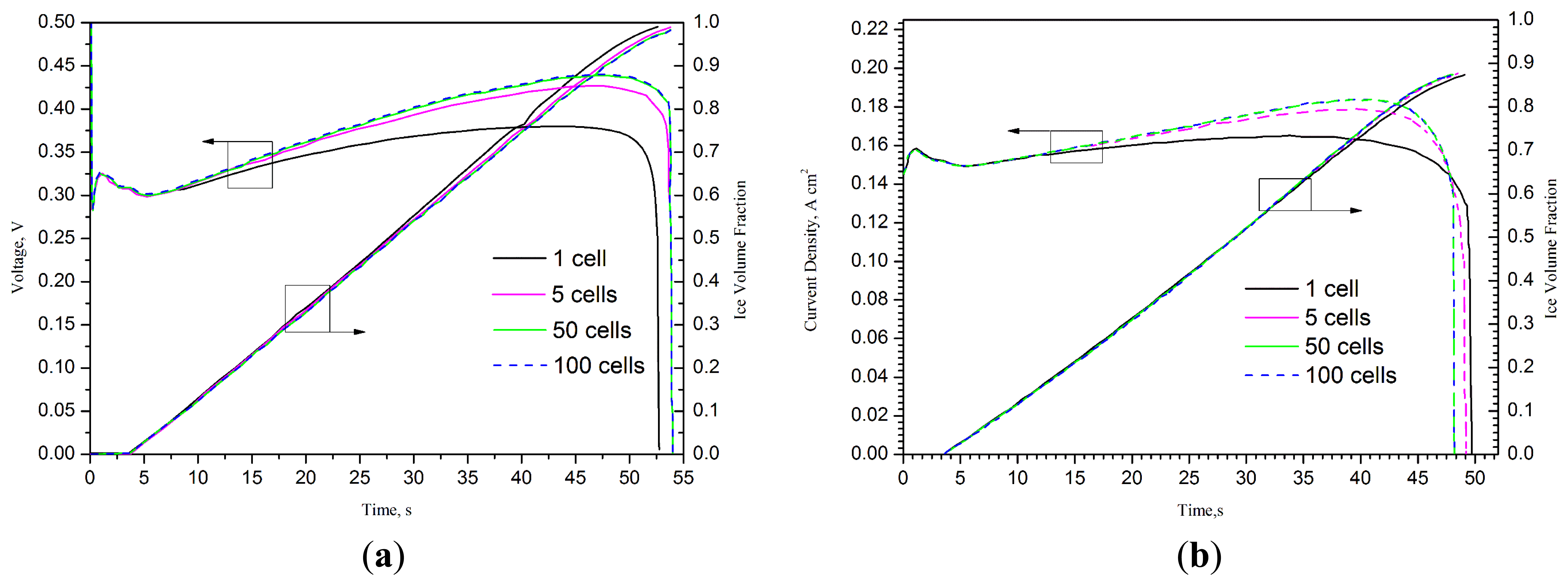
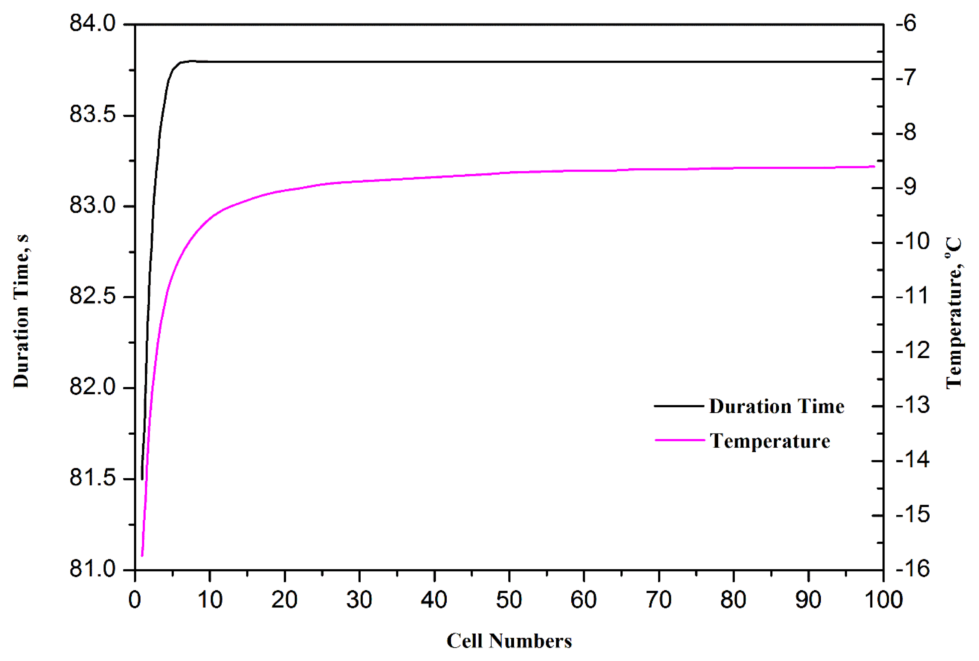
One dimensional model has been developed by different research groups in the early 1990s. For instance, Springer et al. [38,72] described a one dimensional, isothermal, steady-stated model for a complete PEMFC using Nafion® 117 membrane as model electrolyte. With the assumption that excess liquid water is well and finely dispersed in electrode, the water content across the membrane was assumed at a constant level [73,74]. In these one-dimensional models [38,72–81], the basic formulations are based on the assumption of continuity. These formulations have been widely used in many of the subsequent numerical studies. Sundaresan et al. [75] presented a one-dimensional analytical model for cold start of PEMFC to predict the temperature for single cell by performing energy balance and heat transfer analysis. Khandelwal et al. [76] also developed a one-dimensional analytical model. In this model, the startup capability at subfreezing temperature of PEMFC was assessed and the majority of the startup performance was also presented. Mao et al. [37] developed a different one-dimensional analytical model, which can predict not only the temperature distribution, but also the quantity of ice formation in CL, the effects of water transport and current density are also taken into account. A series of significant parameters were drawn out by Wang et al. [60,77] with analytical studies. The numerical models in references [60,75–77] are not very accurate and comprehensive and they can only roughly predict the startup capacity. Multi-dimensional and multiphase models are needed to study the basic theory. To study the cold start processes and performance optimization for PEMFC stacks, Zhou et al. [78] developed a one dimensional model, in which the effects of cell number, start-up current/voltage, external heating and variable heating and load control (VHLC) were systematically investigated. Figure 5 shows the effect of stack cell numbers on the time durations and final volume averaged stack temperatures for the failed unassisted cold start processes from −20 °C at 0.1 A cm−2. It can be clearly seen that the startup process can last longer and the final temperature reached is higher with more cells in a cell stack.
Figure 6 shows the evolution of the average cell voltage/current density and average ice volume fraction in cathode CLs of different stacks starting from −20 °C. The evolutions of stack voltage and average ice volume fraction in cathode CLs of the 20-cell stack starting from −20 °C at 0.15 A cm−2 with the two end surfaces with/without thermal insulation and with/without external heating are also studied in this model. Du et al. [82] developed a one dimensional maximum power cold start model of PEMFC, which founded that the current density is generally kept at high levels with the presented model compared with other cold start models.
Hsing et al. [81] and Futerko et al. [83] developed a two-dimensional model to study the water transport and the resistance of membranes in PEMFC, respectively. Ahluwalia et al. [84] presented a two-dimensional model and the results showed that managing the buildup of ice is the key to obtain a successful self-start. Results from this model suggested that for rapid self-start, it is desirable to operate the stack near short-circuit conditions. Meng [85] developed a transient multiphase two-dimensional PEMFC model to show that the membrane was very important during the cold start process of a fuel cell by absorbing the produced water and becoming hydrated. Since both one-dimensional and two-dimensional models have some drawbacks, more and more researchers started to use three-dimensional multi-phase flow model.
Mao et al. [86] developed a multiphase and transient model to describe the transport and electrochemical processes with ice formation during cold start of PEMFCs. This model accounted for the transport of water at low temperatures, ice formation and growth in CL and GDL, heat transfer with phase change, oxygen transport, electrochemical kinetics, and their mutual interactions. Extensive experimental data was used to predict the cold start performance of PEMFCs as well as to reveal three-dimensional distributions of current density, temperature, membrane water content and ice fraction in the CL. Jiao et al. [10] also developed a three-dimensional multiphase model of cold start processes in PEMFC, including different process: water freezing in the membrane, the non-equilibrium mass transfer between the water in the ionomer and the water in the pores of CL, and the water freezing and melting in the CL and GDL. The results indicated that it's better to increase the ionomer fraction in the cathode CL than to increase the size of the membrane in order to reduce ice formation. This model can also be used to evaluate the cold start performance with different design and operating parameters [78,79]. This numerical model was showed in Table 3 with these conservation equations. Jiang et al. [87,88] developed a multiphase, three-dimensional model during the cold start process of PEMFCs. This model is developed to describe non-isothermal cold start of a PEMFC and to delineate intricate interactions between ice formation and heat generation during cold start [87]. The conclusion was drawn that more water was transported into the membrane leading to less ice formation in CL with the existence of a rising cell temperature. In addition, pre-startup conditions also had a significant influence on cold start. In later research [88], potentiostatic start-up of a PEMFC from subfreezing temperatures was explored. It was found that potentiostatic start-up exhibited more advantages over its galvanostatic counterpart only when the membrane is dry prior to a cold start with sufficient gas purge. In addition, it was found that lowering the cell thermal mass significantly improves the performance of potentiostatic start-up. Ko et al. [89] presented a three-dimensional, non-isothermal, electrochemical-transport coupled cold start mode to study the metallic bipolar plate which was considered as a replacement for a conventional graphite bipolar plate for automotive fuel cells. Qin et al. [90] proposed a two-phase flow model for the cathode side of a PEMFC to study the liquid water flooding in micro gas channels. Ko et al. [91] developed a three-dimensional multiphase transient model to investigate key physical and transport phenomena during the cold start of a PEMFC. Recently, Luo et al. [92] developed a three-dimensional multiphase PEMFC stack model for automotive applications. The analysis in their study showed that the cold start performance could be better with more cells in a cell stack. The voltage decreased more slowly; the temperature increased faster, and no apparent difference in voltage existed among the different individual cells in a stack when the reactant gases were evenly supplied to each cell. Ko et al. [93] developed a three dimensional model to study the effects of key parameters of CLs on cold start behavior of PEMFCs and in the end provided a guidance to design and optimize a PEMFC to improve the cold start capability. Another numerical study was conducted to study the effects of a dual-function MPL under subfreezing to normal temperatures [94].
5.2. Isothermal and Non-Isothermal Models
Isothermal cold start of PEMFC can be easily realized in laboratories by using a single cell fixture with sufficiently large thermal mass and isothermal cold start provides the most conservative scenario to examine the impacts of MEA materials and designs on performance of PEMFC cold start. Hertwig et al. [95] developed an isothermal model of a single membrane electrode unit to calculate the concentration, temperature and flow- speed distributions and to optimize the structures of PEMFC. Tajiri et al. [48] developed an isothermal cold start model to study intrinsic cold start capability of the MEA with sufficiently large thermal mass to fix the cell temperature constant at the startup ambient temperature. From this study, a conclusion was drawn that the membrane was a key component to enhance the intrinsic capability of isothermal cold start from −30 °C. It was also suggested that the cold start performance decreased dramatically when the current density was high enough.
In practice, when the waste heat is produced with the power generation process, the cell temperature will increase. Therefore, the cold start of PEMFCs is inherently non-isothermal. In order to describe the cold start process more clearly and factually, non-isothermal cold start models [68,85,87,88,96] were developed in recent years. Meng [68,85] reported two-phase non-thermal models to investigate the effects of liquid water transport and heat transfer phenomena on the transient responses of a PEMFC undergoing a step change of cell voltage. This result showed that the MPL is very important in preventing liquid flooding. Jiang et al. [87,88,96] also studied the non-isothermal cold start characteristics of PEMFC and the influences of different design and operating parameters on cold start performance were studied in detail. They proposed that a lumped stack thermal model cannot adequately describe the thermal requirement of PEMFC cold start. It was also found that more water transported into the membrane and less ice formation occurs in the cathode CL in the presence of rising cell temperature.
6. Experimental Works on Cold Start of PEMFC
More and more experimental studies [11–13,42,44,48–50,55,96–110] have been performed simultaneously with numerical simulations to study the cell structure parameters and working conditions. Thompson et al. [11] launched the research of the impact of F/T cycle on MEA, and the results showed that for membranes with water contents above λ = 8, the calorimetry and conductivity curves merged at low temperature, suggesting the formation of a common acid hydrate with similar network connectivity. For lower starting water contents, the low-temperature conductivity drops rapidly with λ. Cappadonia et al. [12,13] measured the Nafion membrane conductivity with experiments at different subfreezing temperatures from 140 K to room temperature, and studied the relationship of conductivity of Nafion 117 membranes with temperature and water content. Cho et al. [44,45] studied the F/T cycles at −10 °C, and the results showed that the PEM performance may decrease with unpurged initial condition. It was found that the performance degradation rate can be greatly reduced by using the solution-purging method employing either 30% methanol or 35% ethylene glycol solution as an antifreeze solution. Tajiri et al. [48,109] designed experimental procedures aimed at elucidating fundamentals of polymer electrolyte fuel cell startup from subzero temperatures. The effects of MEA characteristics and initial water content on PEMFC cold start were investigated as key targets. McDonald et al. [49] conducted an ex situ F/T study, Meyers et al. [55] measured the high frequency resistance of a PEMFC in different periods and observed the decrements of membrane conductivity at subfreezing temperature. Yan et al. [50] focused on the effect of startup temperature on cold start performance and found that the cell was capable of starting operation at −5 °C without irreversible performance loss when the cell was initially dry. In Hou's et al. [100,101] study, it was found that membrane performance reduction does not have a major impact on the cold start of PMFCs. Guo et al. [99] conducted an experimental study on the physical properties and performance of MEA, and their observations in this study suggested that lowering the water content within the MEA could be an effective method to prevent it from being severely damaged due to F/T cycles. St-Pierre et al. [105] pointed out that additional work was required in several areas, including modeling, measurement methods and fuel cell design optimization based on a judicious selection of available approaches. Thompson et al. [110] experimentally determined the oxygen reduction reaction kinetics for PEMFCs operating at subfreezing temperatures and no significant change in the oxygen reduction reaction kinetics was observed. Tabe et al. [107] investigated the ice distribution in a cathode CL during the process of cold start. The results showed that at higher startup current densities, ice grew from the membrane side to the GDL side. Tabe et al. [108] also conducted an experimental and microscopic investigation to explore the freezing mechanism in the cell. The freezing mechanism was classified into two types: freezing in the cathode CL at very low temperature, and freezing due to super cooled water at the interface between the CL and the GDL near 0 °C. It was found that the water produced freezes only inside the cathode CL at −20 °C, and that the performance of the cell without an MPL before and after the −10 °C cold start is poorer than with the MPL. Santamaria et al. [104] studied cold start with different types of flow-field (parallel and interdigitated flow-field). Hwang et al. [102] investigated the degradation of CLs associated with phase change in PEMFCs. Ko et al. [89,103] studied the impacts of metallic bipolar plates and dual-function MPL to improve the cold-start capability of PEMFCs. All these researches [89,102–104] are aimed at optimizing the fuel cell to improve the cold start performance. Hirakata et al. [111] conducted a series of experiments to study the effects of a GDL with a hydrophilic layer between the MPL and the carbon paper on the PEMFC performance. The results showed that PEMFC performance can be greatly improved with the hydrophilic layer over a wide range of operating conditions, including subfreezing temperatures. In another research [112], a detailed study of the effect of the pore diameter of the GDLs on the performance of PEMFCs in cold start conditions was carried out.
7. Cold Start Strategies
Although subfreezing temperatures have many adverse effects on PEMFC startup, it is still possible to achieve the desired PEMFC performance for commercial applications by adopting appropriate cold start strategies. In literatures, many researchers and some of the world largest automotive companies have carried out many attempts. Jiang et al. [88] presented a potentiostatic startup method at subfreezing temperatures. Due to the hydration of membrane and rising cell temperature, potentiostatic startup features a drastic increase in current density in the course of a cold start, thus leading to substantially more heat generation and a more rapid cell warm up. St-Pierre et al. [105] compared two different kinds of dehumidification, namely, dry gas purge immediately after the fuel cell stopped and dry gas purge after the fuel cell cooled down. The results demonstrated that the cell performance decreased continuously at high current densities when the former method was used. No significant cell performance decay was observed when the latter method was adopted. Ko et al. [103] adopted MPL in PEMFC as MPL is able to expand the ice storage capacity of the electrode into the MPL region. Moreover, the existence of MPL can greatly enhance the capacity of water transportation.
For rapid startup and minimization of the damage to fuel cell, warming up the fuel cell before starting is undoubtedly the most viable strategy. In this regard, many patents have been filed. Reiser et al. [47] and Rock et al. [113] invented a method to accelerate the startup process of the fuel cell from subfreezing temperature by heating the MEA while it is cold to thaw it out. The method can be applied to single cell as well as cell stacks. Yang et al. [114] and Reiser et al. [47] addressed temperature concerns during startup and shutdown of a cell stack by using the coolant systems. When in cold start process, it enables coolant stream to pass through the channels in the cell and as a result, raising the cell temperature. With the methods proposed by Korytnikov et al. [115,116], a PEMFC system can be efficiently started at a temperature near or below freezing temperature. Referring to this method, fuel (hydrogen or hydrogen-rich reactant gas) was filled in the anode chamber to heat the fuel cell. Dewey [117] also employed a startup heater coupled to a cold plate that warms a stack coolant during system startup. In order to prevent Tlocal of the stack from rising above the limit temperature that might cause damage to the fuel cell, Thompson et al. [118] developed a new method to determine Tlocal of fuel cell stack during stack startup. When Tlocal approaches the predetermined temperature, a cooling fluid flow will be started. Desrosiers et al. [119] adapted a thermal management system to solve the problems of heat transfer and liquid flow, such as heating the stack during startup of the stack at subfreezing temperature.
8. Conclusions
Startup at subfreezing temperatures is a great challenge that impedes the commercialization process of PEMFC in automotive and portable devices. This paper focused on this topic and discussed the main aspects related to cold start. First, the state and phase changes of water in PEMFC were discussed. As shown in Section 2, water with different states and the phase change between these states were discussed in details. Second, the impacts of water freezing on different components of PEMFC were analyzed. Third, different models on cold start of PEMFC were reviewed and classified into different categories according to its dimension and process. Fourth, the experimental works on cold start of PEMFC were discussed. Finally, cold start strategies were summarized. Although many new fuel cell systems as well as different analytical models have been developed, more insight has to be gained toward the comprehensive understanding of the cold start issue of PEMFC. In order to achieve the cold startup of PEMFC rapidly without any performance degradation, novel and high performance PEMFC materials, advanced PEMFC system, and appropriate startup strategies are demanded.
Acknowledgments
This work is financially supported by the National Nature Science Foundation of China (No. 51376058).
Conflicts of Interest
The authors declare no conflict of interest.
References
- Spiegel, C. Designing and Building Fuel Cells; McGraw-Hill: New York, NY, USA, 2007. [Google Scholar]
- Hinaje, M.; Raël, S.; Noiying, P.; Nguyen, D.A.; Davat, B. An equivalent electrical circuit model of proton exchange membrane fuel cells based on mathematical modelling. Energies 2012, 5, 2724–2744. [Google Scholar]
- Wan, Z.; Liu, J.; Luo, Z.; Tu, Z.; Liu, Z.; Liu, W. Evaluation of self-water-removal in a dead-ended proton exchange membrane fuel cell. Appl. Energy 2013, 104, 751–757. [Google Scholar]
- Tu, Z.; Zhang, H.; Luo, Z.; Liu, J.; Wan, Z.; Pan, M. Evaluation of 5 kW proton exchange membrane fuel cell stack operated at 95 °C under ambient pressure. J. Power Sources 2013, 222, 277–281. [Google Scholar]
- Pei, H.; Liu, Z.; Zhang, H.; Yu, Y.; Tu, Z.; Wan, Z.; Liu, W. In situ measurement of temperature distribution in proton exchange membrane fuel cell I a hydrogen–air stack. J. Power Sources 2013, 227, 72–79. [Google Scholar]
- Larminie, J.; Dicks, A. Fuel Cell Systems Explained, 2nd ed.; John Wiley & Sons Ltd: Chichester, UK, 2003. [Google Scholar]
- Jiao, K.; Li, X. Water transport in polymer electrolyte membrane fuel cells. Prog. Energy Combust. Sci. 2011, 37, 221–291. [Google Scholar]
- Markötter, H.; Manke, I.; Kuhn, R.; Arlt, T.; Kardjilov, N.; Hentschel, M.P.; Kupsch, A.; Lange, A.; Hartnig, C.; Scholta, J. Neutron tomographic investigations of water distributions in polymer electrolyte membrane fuel cell stacks. J. Power Sources 2012, 219, 120–125. [Google Scholar]
- Li, X. Principles of Fuel Cells; Taylor & Francis: New York, NY, USA, 2006. [Google Scholar]
- Jiao, K.; Li, X. Three-dimensional multiphase modeling of cold start processes in polymer electrolyte membrane fuel cells. Electrochim. Acta 2009, 54, 6876–6891. [Google Scholar]
- Thompson, E.L.; Capehart, T.W.; Fuller, T.J.; Jorne, J. Investigation of low-temperature proton transport in Nafion using direct current conductivity and differential scanning calorimetry. J. Electrochem. Soc. 2006, 153, A2351–A2362. [Google Scholar]
- Cappadonia, M.; Erning, J.W.; Stimming, U. Proton conduction of Nafion® 117 membrane between 140 K and room temperature. J. Electroanal. Chem. 1994, 376, 189–193. [Google Scholar]
- Cappadonia, M.; Erning, J.W.; Niaki, S.M.S.; Stimming, U. Conductance of Nafion 117 membranes as a function of temperature and water content. Solid State Ionics 1995, 77, 65–69. [Google Scholar]
- Yoshida, H.; Miura, Y. Behavior of water in perfluorinated ionomer membranes containing various monovalent cations. J. Membr. Sci. 1992, 68, 1–10. [Google Scholar]
- Pineri, M.; Volino, F.; Escoubes, M. Evidence for sorption–desorption phenomena during thermal cycling in highly hydrated perfluorinated membranes. J. Polym. Sci. Polym. Phys. Ed. 1985, 23, 2009–2020. [Google Scholar]
- Nakamura, K.; Hatakeyama, T.; Hatakeyama, H. Relationship between hydrogen bonding and bound water in polyhydroxystyrene derivatives. Polymer 1983, 24, 871–876. [Google Scholar]
- Kim, Y.S.; Dong, L.M.; Hickner, M.A.; Glass, T.E.; Webb, V.; McGrath, J.E. State of water in disulfonated poly (arylene ether sulfone) copolymers and a perfluorosulfonic acid copolymer (Nafion) and its effect on physical and electrochemical properties. Macromolecules 2003, 36, 6281–6285. [Google Scholar]
- Siu, A.; Schmeisser, J.; Holdcroft, S. Effect of water on the low temperature conductivity of polymer electrolytes. J. Phys. Chem. B 2006, 110, 6072–6080. [Google Scholar]
- Eikerling, M.; Kornyshev, A.A.; Stimming, U. Electrophysical properties of polymer electrolyte membranes: A random network model. J. Phys. Chem. B 1997, 101, 10807–10820. [Google Scholar]
- Eikerling, M.; Kharkats, Y.I.; Kornyshev, A.A.; Volfkovich, Y.M. Phenomenological theory of electro-osmotic effect and water management in polymer electrolyte proton-conducting membranes. J. Electrochem. Soc. 1998, 145, 2684–2699. [Google Scholar]
- Roudgar, A.; Narasimachary, S.P.; Eikerling, M. Hydrated arrays of acidic surface groups as model systems for interfacial structure and mechanisms in PEMS. J. Phys. Chem. B 2006, 110, 20469–20477. [Google Scholar]
- Bultel, Y.; Wiezell, K.; Jaouen, F.; Ozil, P.; Lindbergh, G. Investigation of mass transport in gas diffusion layer at the air cathode of a PEMFC. Electrochim. Acta 2005, 51, 474–488. [Google Scholar]
- Sivashinsky, N.; Tanny, G.B. The state of water in swollen ionomers containing sulfonic acid salts. J. Appl. Polym. Sci. 1981, 26, 2625–2637. [Google Scholar]
- Chen, R.S.; Jayakody, J.P.; Greenbaum, S.G.; Pak, Y.S.; Xu, G.; McLin, M.G.; Fontanella, J.J. Studies of water in Nafion membranes: Using deuteron and oxygen-17 nuclear magnetic resonance, and dielectric relaxation techniques. J. Electrochem. Soc. 1993, 140, 889–895. [Google Scholar]
- Asaka, K.; Fujiwara, N.; Oguro, K.; Onishi, K.; Sewa, S. State of water and ionic conductivity of solid polymer electrolyte membranes in relation to polymer actuators. J. Electroanal. Chem. 2001, 505, 24–32. [Google Scholar]
- Lu, Z.; Manias, E.; Macdonald, D. Dielectric Relaxation Spectroscopy Studies on Water-Saturated Nafion 117 Membrane. Proceedings of the Electrochemical Society 204th National Meeting, Orlando, FL, USA, 12–16 October 2003.
- Saito, M.; Hayamizu, K.; Okada, T. Temperature dependence of ion and water transport in perfluorinated ionomer membranes for fuel cells. J. Phys. Chem. B 2005, 109, 3112–3119. [Google Scholar]
- Tan, S.; Bélanger, D. Characterization and transport properties of Nafion/polyaniline composite membranes. J. Phys. Chem. B 2005, 109, 23480–23490. [Google Scholar]
- Siu, A.; Pivovar, B.; Horsfall, J.; Lovell, K.V.; Holdcroft, S. Dependence of methanol permeability on the nature of water and the morphology of graft copolymer proton exchange membranes. J. Polym. Sci. Part B Polym. Phys. 2006, 44, 2240–2252. [Google Scholar]
- Corti, H.R.; Nores-Pondal, F.; Buera, M.P. Low temperature thermal properties of Nafion 117 membranes in water and methanol-water mixtures. J. Power Sources 2006, 161, 799–805. [Google Scholar]
- Mukundan, R.; Kim, Y.S.; Garzon, F.H.; Pivovar, B. Freeze/thaw effects in PEM fuel cells. ECS Trans. 2006, 1, 403–413. [Google Scholar]
- Walsby, N.; Hietala, S.; Maunu, S.L.; Sundholm, F.; Kallio, T.; Sundholm, G. Water in different poly(styrene sulfonic acid)-grafted fluoropolymers. J. Appl. Polym. Sci. 2002, 86, 33–42. [Google Scholar]
- Alink, R.; Gerteisen, D. Modeling the liquid water transport in the gas diffusion layer for polymer electrolyte membrane fuel cells using a water path network. Energies 2013, 6, 4508–4530. [Google Scholar]
- Pasaogullari, U.; Wang, C.Y. Liquid water transport in gas diffusion layer of polymer electrolyte fuel cells. J. Electrochem. Soc. 2004, 151, A399–A406. [Google Scholar]
- Pasaogullari, U.; Wang, C.Y.; Chen, K.S. Two-phase transport in polymer electrolyte fuel cells with bilayer cathode gas diffusion media. J. Electrochem. Soc. 2005, 152, A1574–A1582. [Google Scholar]
- Chan, D.-S.; Hsueh, K.L. A transient model for fuel cell cathode-water propagation behavior inside a cathode after a step potential. Energies 2010, 3, 920–939. [Google Scholar]
- Mao, L.; Wang, C.Y. Analysis of cold start in polymer electrolyte fuel cells. J. Electrochem. Soc. 2007, 154, B139–B146. [Google Scholar]
- Springer, T.E.; Zawodzinski, T.A.; Gottesfeld, S. Polymer electrolyte fuel cell model. J. Electrochem. Soc. 1991, 138, 2334–2342. [Google Scholar]
- Yu, Y.; Tu, Z.; Zhan, Z.; Pan, M. Gravity effect on the performance of PEM fuel cell stack with different gas manifold positions. Int. J. Energy Res. 2012, 36, 845–855. [Google Scholar]
- Wan, Z.; Wan, J.; Liu, J.; Tu, Z.; Pan, M.; Liu, Z.; Liu, W. Water recovery and air humidification by condensing the moisture in the outlet gas of a proton exchange membrane fuel cell stack. Appl. Therm. Eng. 2012, 42, 173–178. [Google Scholar]
- Ji, M.; Wei, Z. A review of water management in polymer electrolyte membrane fuel cells. Energies 2009, 2, 1057–1106. [Google Scholar]
- Wilson, M.S.; Valerio, J.A.; Gottesfeld, S. Low platinum loading electrodes for polymer electrolyte fuel cells fabricated using thermoplastic ionomers. Electrochim. Acta 1995, 40, 355–363. [Google Scholar]
- Cho, E. A Study on Performance Degradation of PEMFC by Water Freezing. Proceedings of the Workshop on Fuel Cell Operations at Sub-Freezing Temperatures, Phoenix, AZ, USA, 1–2 February 2005.
- Cho, E.; Ko, J.J.; Ha, H.Y.; Hong, S.A.; Lee, K.Y.; Lim, T.W.; Oh, I.H. Characteristics of the PEMFC repetitively brought to temperatures below 0 °C. J. Electrochem. Soc. 2003, 150, A1667–A1670. [Google Scholar]
- Cho, E.; Ko, J.J.; Ha, H.Y.; Hong, S.A.; Lee, K.Y.; Lim, T.W.; Oh, I.H. Effects of water removal on the performance degradation of PEMFCs repetitively brought to <0 °C. J. Electrochem. Soc. 2004, 151, A661–A665. [Google Scholar]
- Oszcipok, M.; Riemann, D.; Kronenwett, U.; Kreideweis, M.; Zedda, A. Statistic analysis of operational influences on the cold start behaviour of PEM fuel cells. J. Power Sources 2005, 145, 407–415. [Google Scholar]
- Reiser, C.A.; Sribnik, F.F. Fuel Cell Stack Melting of Coolant Water during Frozen Startup U.S. Patent 6, 986, 958, 17 January 2006.
- Tajiri, K.; Tabuchi, Y.; Wang, C.-Y. Isothermal cold start of polymer electrolyte fuel cells. J. Electrochem. Soc. 2007, 154, B147–B152. [Google Scholar]
- McDonald, R.C.; Mittelsteadt, C.K.; Thompson, E.L. Effects of deep temperature cycling on Nafion® 112 membranes and membrane electrode assemblies. Fuel Cells 2004, 4, 208–213. [Google Scholar]
- Yan, Q.; Toghiani, H.; Lee, Y.-W.; Liang, K.; Causey, H. Effect of sub-freezing temperatures on a PEM fuel cell performance, startup and fuel cell components. J. Power Sources 2006, 160, 1242–1250. [Google Scholar]
- Mukundan, R.; Lujan, R.; Davey, J.R.; Spendelow, J.S.; Hussey, D.S.; Jacobson, D.L.; Arif, M.; Borup, R. Ice formation in PEM fuel cells operated isothermally at sub-freezing temperatures. ECS Trans. 2009, 25, 345–355. [Google Scholar]
- Xie, J.; Wood, D.L.; Wayne, D.M.; Zawodzinski, T.A.; Atanassov, P.; Borup, R.L. Durability of PEFCs at high humidity conditions. J. Electrochem. Soc. 2005, 152, A104–A113. [Google Scholar]
- Pivovar, B. MEA and Interfacial Issues in Low Temperature Fuel Cells. Proceedings of the Workshop on Sub-Freezing Effects, Phoenix, AZ, USA, 1–2 February 2005.
- Mao, L.; Tajiri, K.; Ge, S.; Yang, X.G.; Wang, C.Y. Cold Start of Polymer Electrolyte Fuel Cells—Three-Phase Modeling and Experiments. Proceedings of the 208th Electrochemical Society Meeting, Los Angeles, CA, USA, 16–21 October 2005; Volume 2005-2, pp. 16–21.
- Meyers, J.P. Fundamental Issues in Subzero PEMFC Startup and Operation. Proceedings of the DOE Freeze Workshop, UTC Fuel Cell, Los Alamos, NM, USA, 1 February 2005.
- Gaylord, R. Stationary Applications and Freeze/Thaw. Proceedings of the Workshop on Fuel Cell Operations at Sub-Freezing Temperatures, Phoenix, AZ, USA, 1–2 February 2005.
- Yang, X.G.; Tabuchi, Y.; Kagami, F.; Wang, C.-Y. Durability of membrane electrode assemblies under polymer electrolyte fuel cell cold-start cycling. J. Electrochem. Soc. 2008, 155, B752–B761. [Google Scholar]
- Yoon, W.; Huang, X. A multiphysics model of PEM fuel cell incorporating the cell compression effects. J. Electrochem. Soc. 2010, 157, B680–B690. [Google Scholar]
- Jiao, K.; Alaefour, I.E.; Karimi, G.; Li, X. Cold start characteristics of proton exchange membrane fuel cells. Int. J. Hydrog. Energy 2011, 36, 11832–11845. [Google Scholar]
- Wang, Y.; Mukherjee, P.P.; Mishler, J.; Mukundan, R.; Borup, R.L. Cold start of polymer electrolyte fuel cells: Three-stage startup characterization. Electrochim. Acta 2010, 55, 2636–3644. [Google Scholar]
- Wang, C.Y. Fundamental models for fuel cell engineering. Chem. Rev. 2004, 104, 4727–4765. [Google Scholar]
- Wang, Y.; Wang, C.Y. Transient analysis of polymer electrolyte fuel cells. Electrochim. Acta 2005, 50, 1307–1315. [Google Scholar]
- Madhusudana, R.R.; Rengaswamy, R. A distributed dynamic model for chronoamperometry, chronopotentiometry and gas starvation studies in PEM fuel cell cathode. Chem. Eng. Sci. 2006, 61, 7393–7409. [Google Scholar]
- Wang, Y.; Wang, C.Y. Dynamics of polymer electrolyte fuel cells undergoing load changes. Electrochim. Acta 2006, 51, 3924–3933. [Google Scholar]
- Wang, Y.; Wang, C.Y. Two-phase transients of polymer electrolyte fuel cells. J. Electrochem. Soc. 2007, 154, B636–B643. [Google Scholar]
- Hu, G.; Fan, J. Transient computation fluid dynamics modeling of a single proton exchange membrane fuel cell with serpentine channel. J. Power Sources 2007, 165, 171–184. [Google Scholar]
- Shah, A.A.; Kim, G.S.; Sui, P.C.; Harvey, D. Transient non-isothermal model of a polymer electrolyte fuel cell. J. Power Sources 2007, 163, 793–806. [Google Scholar]
- Meng, H. Numerical investigation of transient responses of a PEM fuel cell using a two-phase non-isothermal mixed-domain model. J. Power Sources 2007, 171, 738–746. [Google Scholar]
- Chang, S.M.; Chu, H.S. A transient model of PEM fuel cells based on a spherical thin film-agglomerate approach. J. Power Sources 2007, 172, 790–798. [Google Scholar]
- Shah, A.A.; Sui, P.C.; Kim, G.S.; Ye, S. A transient PEMFC model with CO poisoning and mitigation by O2 bleeding and Ru-containing catalyst. J. Power Sources 2007, 166, 1–21. [Google Scholar]
- Shan, Y.; Choe, S.Y.; Choi, S.-H. Unsteady 2D PEM fuel cell modeling for a stack emphasizing thermal effects. J. Power Sources 2007, 165, 196–209. [Google Scholar]
- Springer, T.E.; Wilson, M.S.; Gottesfeld, S. Modeling and experimental diagnostics in polymer electrolyte fuel cells. J. Electrochem. Soc. 1993, 140, 3513–3526. [Google Scholar]
- Bernardi, D.M.; Verbrugge, M.W. Mathematical model of a gas diffusion electrode bonded to a polymer electrolyte. AIChE J. 1991, 37, 1151–1163. [Google Scholar]
- Bernardi, D.M.; Verbrugge, M.W. A mathematical model of the solid-polymer-electrolyte fuel cell. J. Electrochem. Soc. 1992, 139, 2477–2491. [Google Scholar]
- Sundaresan, M.; Moore, R.M. Polymer electrolyte fuel cell stack thermal model to evaluate sub-freezing startup. J. Power Sources 2005, 145, 534–545. [Google Scholar]
- Khandelwal, M.; Lee, S.; Mench, M.M. One-dimensional thermal model of cold-start in a polymer electrolyte fuel cell stack. J. Power Sources 2007, 172, 816–830. [Google Scholar]
- Wang, Y. Analysis of the key parameters in the cold start of polymer electrolyte fuel cells. J. Electrochem. Soc. 2007, 154, B1041–B1048. [Google Scholar]
- Zhou, Y.; Luo, Y.; Yu, S.; Jiao, K. Modeling of cold start processes and performance optimization for proton exchange membrane fuel cell stacks. J. Power Sources 2014, 247, 738–748. [Google Scholar]
- Jiao, K.; Li, X. Effects of various operating and initial conditions on cold start performance of polymer electrolyte membrane fuel cells. Int. J. Hydrog. Energy 2009, 34, 8171–8184. [Google Scholar]
- Jiao, K.; Li, X. Cold start analysis of polymer electrolyte membrane fuel cells. Int. J. Hydrog. Energy 2010, 35, 5077–5094. [Google Scholar]
- Hsing, I.M.; Futerko, P. Two-dimensional simulation of water transport in polymer electrolyte fuel cells. Chem. Eng. Sci. 2000, 55, 4209–4218. [Google Scholar]
- Du, Q.; Jia, B.; Luo, Y.; Chen, J.; Zhou, Y.; Jiao, K. Maximum power cold start mode of proton exchange membrane fuel cell. Int. J. Hydrog. Energy 2014, 39, 8390–8400. [Google Scholar]
- Futerko, P.; Hsing, I.M. Two-dimensional finite-element method study of the resistance of membranes in polymer electrolyte fuel cells. Electrochim. Acta 2000, 45, 1741–1751. [Google Scholar]
- Ahluwalia, R.K.; Wang, X. Rapid self-start of polymer electrolyte fuel cell stacks from subfreezing temperatures. J. Power Sources 2006, 162, 502–512. [Google Scholar]
- Meng, H. A PEM fuel cell model for cold-start simulations. J. Power Sources 2008, 178, 141–150. [Google Scholar]
- Mao, L.; Wang, C.Y.; Tabuchi, Y. A multiphase model for cold start of polymer electrolyte fuel cells. J. Electrochem. Soc. 2007, 154, B341–B351. [Google Scholar]
- Jiang, F.; Fang, W.; Wang, C.-Y. Non-isothermal cold start of polymer electrolyte fuel cells. Electrochim. Acta 2007, 53, 610–621. [Google Scholar]
- Jiang, F.; Wang, C.Y. Potentiostatic start-up of PEMFCs from subzero temperatures. J. Electrochem. Soc. 2008, 155, B743–B751. [Google Scholar]
- Ko, J.; Kim, W.; Hong, T.; Kim, D.; Ju, H. Impact of metallic bipolar plates on cold-start behaviors of polymer electrolyte fuel cells (PEFCs). Solid State Ionics 2012, 225, 260–267. [Google Scholar]
- Qin, C.; Rensink, D.; Fell, S.; Hassanizadeh, S.M. Two-phase flow modeling for the cathode side of a polymer electrolyte fuel cell. J. Power Sources 2012, 197, 136–144. [Google Scholar]
- Ko, J.; Ju, H. Comparison of numerical simulation results and experimental data during cold-start of polymer electrolyte fuel cells. Appl. Energy 2012, 94, 364–374. [Google Scholar]
- Luo, Y.; Guo, Q.; Du, Q.; Yin, Y.; Jiao, K. Analysis of cold start processes in proton exchange membrane fuel cell stacks. J. Power Sources 2013, 224, 99–114. [Google Scholar]
- Ko, J.; Ju, H. Effects of cathode catalyst layer design parameters on cold start behavior of polymer electrolyte fuel cells (PEFCs). Int. J. Hydrog. Energy 2013, 38, 682–691. [Google Scholar]
- Ko, J.; Ju, H. Numerical evaluation of a dual-function microporous layer under subzero and normal operating temperatures for use in automotive fuel cells. Int. J. Hydrog. Energy 2014, 39, 2854–2862. [Google Scholar]
- Hertwig, K.; Martens, L.; Karwoth, R. Mathematical modelling and simulation of polymer electrolyte membrane fuel cells. Part I: Model structure and solving an isothermal one-cell model. Fuel Cells 2003, 2, 61–77. [Google Scholar]
- Jiang, F.; Wang, C.Y.; Chen, K.S. Current ramping: A strategy for rapid start-up of PEMFCs from subfreezing environment. J. Electrochem. Soc. 2010, 157, B342–B347. [Google Scholar]
- Ge, S.; Wang, C.Y. In situ imaging of liquid water and ice formation in an operating PEFC during cold start. Electrochem. Solid State Lett. 2006, 9, A499–A503. [Google Scholar]
- Ge, S.; Wang, C.Y. Characteristics of subzero startup and water/ice formation on the catalyst layer in a polymer electrolyte fuel cell. Electrochim. Acta 2007, 52, 4825–4835. [Google Scholar]
- Guo, Q.; Qi, Z. Effect of freeze-thaw cycles on the properties and performance of membrane-electrode assemblies. J. Power Sources 2006, 160, 1269–1274. [Google Scholar]
- Hou, J.; Yi, B.; Yu, H.; Hao, L.; Song, W.; Fu, Y.; Shao, Z. Investigation of resided water effects on PEM fuel cell after cold start. Int. J. Hydrog. Energy 2007, 32, 4503–4509. [Google Scholar]
- Hou, J.; Yu, H.; Zhang, S.; Sun, S.; Wang, H.; Yi, B.; Ming, P. Analysis of PEMFC freeze degradation at −20 °C after gas purging. J. Power Sources 2006, 162, 513–520. [Google Scholar]
- Hwang, G.S.; Kim, H.; Lujan, R.; Mukundan, R.; Spernjak, D.; Borup, R.L.; Kaviany, M.; Kim, M.H.; Weber, A.Z. Phase-change-related degradation of catalyst layers in proton-exchange-membrane fuel cells. Electrochim. Acta 2013, 95, 29–37. [Google Scholar]
- Ko, J.; Kim, W.G.; Lim, Y.-D.; Ju, H. Improving the cold-start capability of polymer electrolyte fuel cells (PEFCs) by using a dual-function micro-porous layer (MPL): Numerical simulations. Int. J. Hydrog. Energy 2013, 38, 652–659. [Google Scholar]
- Santamaria, A.D.; Bachman, J.; Park, J.W. Cold-start of parallel and interdigitated flow-field polymer electrolyte membrane fuel cell. Electrochim. Acta 2013, 107, 327–338. [Google Scholar]
- St-Pierre, J.; Roberts, J.; Colbow, K.; Campbell, S.; Nelson, A. PEMFC operational and design strategies for subzero environments. J. New Mater. Electrochem. Syst. 2005, 8, 163–176. [Google Scholar]
- Sun, S.; Yu, H.; Hou, J.; Shao, Z.; Yi, B.; Ming, P.; Hou, Z. Catalytic hydrogen/oxygen reaction assisted the proton exchange membrane fuel cell (PEMFC) startup at subzero temperature. J. Power Sources 2008, 177, 137–141. [Google Scholar]
- Tabe, Y.; Ichikawa, R.; Chikahisa, T. Analysis of ice formation process in cathode catalyst layer of PEFC at cold start. Energy Procedia 2012, 28, 20–27. [Google Scholar]
- Tabe, Y.; Saito, M.; Fukui, K.; Chikahisa, T. Cold start characteristics and freezing mechanism dependence on start-up temperature in a polymer electrolyte membrane fuel cell. J. Power Sources 2012, 208, 366–373. [Google Scholar]
- Tajiri, K.; Tabuchi, Y.; Kagami, F.; Takahashi, S.; Yoshizawa, K.; Wang, C.-Y. Effects of operating and design parameters on PEFC cold start. J. Power Sources 2007, 165, 279–286. [Google Scholar]
- Thompson, E.L.; Jorne, J.; Gasteiger, H.A. Oxygen reduction reaction kinetics in subfreezing PEM fuel cells. J. Electrochem. Soc. 2007, 154, B783–B792. [Google Scholar]
- Hirakata, S.; Hara, M.; Kakinuma, K.; Uchida, M.; Tryk, D.A.; Uchida, H.; Watanabe, M. Investigation of the effect of a hydrophilic layer in the gas diffusion layer of a polymer electrolyte membrane fuel cell on the cell performance and cold start behaviour. Electrochim. Acta 2014, 120, 240–247. [Google Scholar]
- Hirakata, S.; Mochizuki, T.; Uchida, M.; Uchida, H.; Watanabe, M. Investigation of the effect of pore diameter of gas diffusion layers on cold start behavior and cell performance of polymer electrolyte membrane fuel cells. Electrochim. Acta 2013, 108, 304–312. [Google Scholar]
- Rock, J.A.; Plant, L.B. Method of Cold Start-Up of a PEM Fuel Cell. Eur. Pat. EP1113516 B1, 28 April 2004. [Google Scholar]
- Yang, D.; Ballinger, E.A.; Condit, D.A. Method and Apparatus for the Operation of Cell Stack Assembly during Subfreezing Temperatures. U.S. Patent 6,596, 426 B2, 22 July 2003. [Google Scholar]
- Korytnikov, K.; Peter, N. Method and Apparatus for Cold-Starting a PEM Fuel Cell (PEMFC), and PEM Fuel Cell System. U.S. Patent 20050227126 A1, 13 October 2005. [Google Scholar]
- Korytnikov, K.; Peter, N. Method and Apparatus for Cold-Starting a PEM Fuel Cell (PEMFC), and PEM Fuel Cell System. World Intellectual Property Organization (WIPO) Patent WO/2005/101561, 8 April 2005. [Google Scholar]
- Dewey, S. FCPM Freeze Start Heater. U.S. Patent 20050277003 A1, 15 December 2005. [Google Scholar]
- Thompson, E.L.; Zhang, Y. Method to Begin Coolant Circulation to Prevent MEA Overheating during Cold Start. U.S. Patent 7,393,602 B2, 1 July 2008. [Google Scholar]
- Desrosiers, K.C.; Laven, A.; Kinkle, D.W.S. System and Methods for Starting and Operating Fuel Cell Systems in Subfreezing Temperatures. U.S. Patent 20080299429 A1, 4 December 2008. [Google Scholar]


| Membrane | Frozen water | Non-frozen water | Free water | Freezing temperature |
|---|---|---|---|---|
| Nafion | - | - | - | From −20 °C to 0 °C [23] |
| Nafion1200EW | - | - | 11.4%–15.2% | From −50°C to 0 °C [15] |
| Nafion1100EW | - | - | 13%–29% | From −60 °C to −40 °C [14] |
| Nafion 117 | - | - | 5%–18% | Around −20 °C [24] |
| Nafion 117 | - | - | 4.2%–24.5% | From −48 °C to −10 °C [13] |
| Nafion 117 | 7%–22% | - | - | From −18 °C to −12 °C [25] |
| Nafion 117 | - | - | λ = 22 | Around −20 °C [26] |
| Nafion 117 | λ = 7.7−8.3 | λ = 12.5−13.1 | λ = 20.8 | Around −20 °C [27] |
| Nafion 117 | - | - | 33% | Around −20 °C [28] |
| Nafion 117 | λ = 9 | λ = 7.7–14 | λ = 20 | From −20 °C to −3 °C [29] |
| Nafion 117 | λ = 6−15 | - | - | From −25 °C to −6 °C [11] |
| Nafion 117 | 1%–23% | - | - | From −35 °C to −25 °C [30] |
| Nafion 117 | - | - | 24.8%, λ = 20.2 | From −17 °C to 5 °C [31] |
| Nafion 105 | - | - | - | From −25 °C to −20 °C [32] |
| Nafion 135 | - | - | - | From −30 °C to −10 °C [17] |
| Component | Location | State of water |
|---|---|---|
| PEM | Ionomer | Ice, liquid water, non-frozen water, frozen water and vapor |
| GDL | Pores | Ice, liquid water and vapor |
| CL | Pores and Ionomer | Ice, liquid water, non-frozen water, frozen water and vapor |
| Flow channel | Everywhere | Vapor and liquid water |
| Property | Conservation equation | Domains |
|---|---|---|
| Mass of gas mixture | Flow channel, GDL and CL | |
| Momentum of gas mixture | Flow channel, GDL and CL | |
| Gas species i: hydrogen, oxygen or vapor | Flow channel, GDL and CL | |
| Liquid water | GDL and CL | |
| Ice | GDL and CL | |
| Water content of non-frozen membrane | Membrane and CL | |
| Water content of frozen membrane | Membrane | |
| Electronic potential | CL, GDL and BP | |
| Ionic potential | Membrane and CL | |
| Energy | All the domains |
© 2014 by the authors; licensee MDPI, Basel, Switzerland. This article is an open access article distributed under the terms and conditions of the Creative Commons Attribution license ( http://creativecommons.org/licenses/by/3.0/).
Share and Cite
Wan, Z.; Chang, H.; Shu, S.; Wang, Y.; Tang, H. A Review on Cold Start of Proton Exchange Membrane Fuel Cells. Energies 2014, 7, 3179-3203. https://doi.org/10.3390/en7053179
Wan Z, Chang H, Shu S, Wang Y, Tang H. A Review on Cold Start of Proton Exchange Membrane Fuel Cells. Energies. 2014; 7(5):3179-3203. https://doi.org/10.3390/en7053179
Chicago/Turabian StyleWan, Zhongmin, Huawei Chang, Shuiming Shu, Yongxiang Wang, and Haolin Tang. 2014. "A Review on Cold Start of Proton Exchange Membrane Fuel Cells" Energies 7, no. 5: 3179-3203. https://doi.org/10.3390/en7053179