1. Introduction
The summer in Southern China is normally hot and humid. In terms of thermal comfort, there are acceptable ranges of dry bulb temperature and the relative humidity, as well as their combinations. It is necessary to provide air-conditioning, but the dehumidification ability of most cooling coils is not effective enough to remove water from the air. In order to improve the level of thermal comfort, the dry bulb temperature within the indoor environment may need to cool the air which leads to the use of extra energy in the heating ventilation and air conditioning (HVAC) system. This is usually achieved by the use of a separate electric heater or an additional heat pump system.
Conventional air-conditioning systems are widely adopted in the buildings of Southern China. Being charged with electricity, the air-conditioning equipment is required to output a given rate of cooling that increases with the temperature of the medium entering the condenser for cooling. The performance of standard air-conditioning systems in Southern China is not remarkable. The high outdoor air temperature, which is around 35 °C in summer, is one of the reasons. On the other hand, the high outdoor air humidity, which is around 95% in summer, is another reason. The achievable coefficient of performance (
COP) of most air-conditioning system is therefore low, in the range of 2.2–2.4 [
1].
Most previous literature research efforts are therefore focused on investigating effective ways to use heat pumps or heat pipe technology for energy savings in this aspect. Mori
et al. [
2] proposed using submarine heat pumps that have a distinct thermodynamic advantage over other thermal stimulation techniques for energy saving potential. Peigné
et al. [
3] designed a system to heat a low-energy building by coupling a heat-recovery ventilation system with a three-fluid heat exchanger located on the chimney of a wood-pellet stove and their case study results showed that heat transfer rates can be predicted with a relative difference lower than 5%. A study by Huang
et al. [
4] fabricated a novel hybrid-structure flat plate heat pipe for a concentrator photovoltaic system and the results indicated that it can reduce thermal resistance by 65% after a supporting structure is added to the heat pipe.
Other related research results have identified that heat pipe (HP) heat exchangers (HXs), having no moving parts, can effectively recover waste heat to reheat the conditioned outdoors to the desired conditions with no additional energy requirements [
5]. In a study by Ahmadzadehtalatapeh
et al. [
6] the impact of Heat Pipe Heat Exchangers (HPHXs) on the performance of an air-conditioning system in a library building was investigated, and the simulation results showed that by the process of pre-cooling and reheating provided by the HPHXs, a total amount of 236.9 MWh energy could be saved in a year. In another study by Srimuang
et al. [
7] the application of heat pipe heat exchangers for heat recovery focused on the energy savings and provideing additional information for the design of heat pipe heat exchangers with optimum conditions in heat recovery systems was reviewed. Yau [
8,
9,
10,
11,
12] conducted a series of experimental studies on the use of HP technology for tropical climates and gave a review of research on the application of heat pipe heat exchangers in air conditioning systems.
From the above statements it is apparent that HP (heat recovery) technology can be used in air-conditioning systems or thermal utilization systems to save cooling or heating energy to achieve the objective of saving energy. However, the feasible use and advantages of HPHX for dedicated ventilation (DV) system to the desired conditions so as to increase COP of the system and avoid additional energy consumption for reheating and dehumidification has not been discussed. Hence, the objective of this study was to test and demonstrate a HPHX combined with a direct-expansion (DX) cooling coil for conditioning of outdoor air (OA) to the desired conditions for minimizing additional dehumidification demands in the space air handler so as to virtually separate the dehumidification and cooling process to save energy.
2. System Description
There are two systems:
- (1)
Fresh air without HPHX—the conventional system;
- (2)
Fresh air with HPHX and Fan Coil Unit (FCU).
2.1. Fresh Air without HPHX—the Conventional System
The analysis of the conventional system is given in this part. The schematic diagram of the system and the air treatment processes in a psychrometric chart are shown in
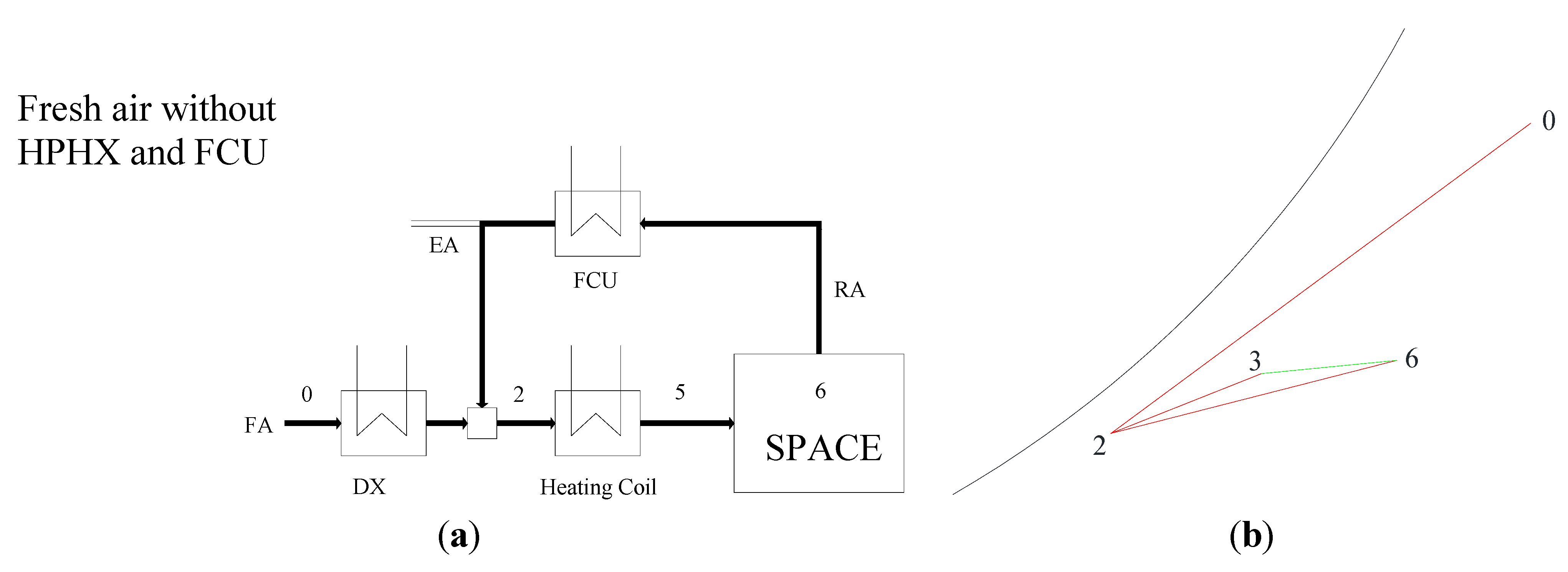
Figure 1a,b, respectively. In this system, the return air (RA, state 6) is cooled and dehumidified by the FCU and the fresh air (FA, state 0) flows through a DX where it is cooled and dehumidified, then mixed to state 2. At this temperature air could not be directly supplied to the space in order to prevent cold-drafts and over-cooling that would cause uncomfortableness. As a result, supply air is also reheated by a heating coil to state 5 before being distributed into the conditioned space. This is the conventional system.
Process details:
0→2: Air cooled inside the DX;
2: The air supplied by the FCU and mixed with the cooled air;
2→5: The cooled air re-heated by the heating coil;
5→6: The space cooling load (SHR) that leads the indoor air to meet the design space conditions.
Figure 1.
(a) The schematic diagram of the fresh air without HPHX and FCU; (b) The air treatment processes of the fresh air without HPHX and FCU in a psychrometric chart: 0. Fresh air, 2. Mixed air, 5. Re-heated air, 6. Space air, EA: Exhaust Air, DX: direct- expansion.
Figure 1.
(a) The schematic diagram of the fresh air without HPHX and FCU; (b) The air treatment processes of the fresh air without HPHX and FCU in a psychrometric chart: 0. Fresh air, 2. Mixed air, 5. Re-heated air, 6. Space air, EA: Exhaust Air, DX: direct- expansion.
2.2. Fresh Air with HPHX and FCU
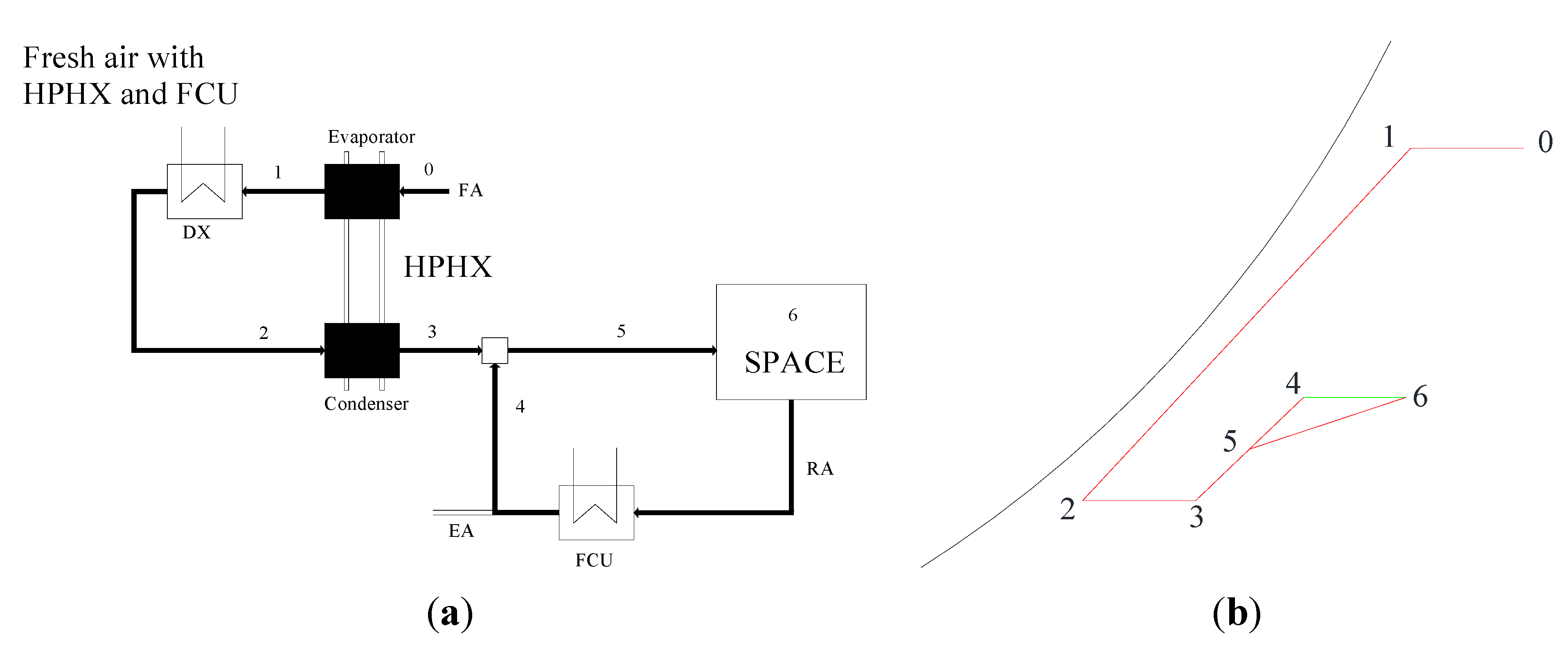
The schematic diagram of the system components and the corresponding psychrometric processes are shown in
Figure 2a,b. Pretreated fresh air is supplied directly to the conditioned space to mix with cooled air leaving the fan-coil units to offset the space load in achieving the desired space conditions.
Process details:
0→1: Air pre-cooled by the heat pipe from the outdoor air condition;
1→2: Pre-cooled air further cooled inside the DX;
2→3: The cooled air re-heated by the heat pipe;
3+4→5: The air supplied by the FCU and mixed with the re-heated air;
5→6: The space cooling load (SHR) leads the indoor air to meet the design space conditions.
Figure 2.
(a) The schematic diagram of the fresh air with HPHX and FCU; (b) The air treatment processes of the fresh air with HPHX and FCU system in a psychrometric chart: 0. Fresh air; 1. Pre-cooled air; 2. Cooled air; 3. Re-heated air; 4. Cooled air supplied by FCU; 5. Mixed air with the re-heated air and the cooled air supplied by FCU; 6. Space air; EA: Exhaust Air; DX: direct-expansion.
The pre-cooling process of HPHX will enhance the cooling capability for the air conditioner, whilst the re-heating process will provide free reheating energy for the overcooled fresh air. The moisture removal capability of the DX in the HVAC systems can be enhanced if the fresh air has been pre-cooled before reaching it.
3. Simulation
The availability of a building’s cooling load profiles are essential for evaluating the feasibility and the energy benefits associated with the use of the proposed system. According to the latest survey of the design conditions and the building construction details which come from representative buildings, the 10 surveyed buildings can provide a representative picture of the design values used in Southern China. Therefore, considering the building construction details, the air-conditioning system characteristics, the occupancy profiles, and the occupation and process load patterns, etc., the 10 buildings have been identified as the sample and typical buildings.
The complex characteristics of buildings 1 to 10 were individually modelled by the use of 18 data files for HTB2 (a model for the thermal environment of building in operation) [
13] simulations in Southern China. HTB2 has been designed as an investigative model of the thermal performance of building. The model was developed to investigate the detailed workings of the building, incorporating many aspects of thermal transport and gain (fabric, ventilation, heating) providing data on short time-scales of minutes and weeks, rather than hours and years [
14].
The outdoor temperature value below 20 °C and the relative humidity value below 50% have not been modeled in these series of models since the models set-up was designed to satisfy the temperature ≥20 °C and the relative humidity ≥50%. It is also because, the hours per year when the outdoor temperature below 20 °C and relative humidity below 50% are relative limited in Southern China.
For HPHX effectiveness, reference is made to manufacturers’ performance data [
15,
16]. It is noted that systems with effectiveness of 0.45 and 0.6 are readily available in the commercial market, and they were therefore selected for further evaluation, whilst for desirable space conditions, reference is made to the design space conditions of buildings 1 to 10. It has been found to range from 22 °C to 24 °C, and at relative humidity 50%, which are at moderately comfortable zones in terms of the psychrometrics.
4. Energy Saving Calculations
To analyze the energy consumption and energy saving potential of the different air systems, the following have been assumed:
- (a)
In these two systems, the state points are the same, from state 0 to state 6. For example: fresh air point (state 0), state 2 and space design point (state 6);
- (b)
The conventional DX carries out its normal cooling and dehumidifying function (process 0–2), but with enhanced latent capacity because of the pre-cooling effect of the HPHX;
- (c)
Air transport between the DX and the HPHX condenser occurs adiabatically;
- (d)
The energy transfer rates in the two sections of the HPHX are equal and opposite {implying that (h0 − h1) = (h3 − h2) since the air mass flow rates are equal};
- (e)
The space has significant latent loads that would normally necessitate reheat in a conventional HVAC system.
4.1. The Energy Saving Calculation for the Fresh Air System
Without the HPHX, the net total cooling and reheating load for fresh air treatment,
QDXN,O &
HDX,O, would be:
where:
ρ = air density, kg/m3;
Cpa = air specific heat, kJ/kg·K;
VFA = fresh air supply flow rate, m3/s;
h0 = outdoor air enthalpy hourly, kJ/kg;
h2 = leaving cooling air enthalpy in DX, kJ/kg;
t2 = leaving cooling air temperature in DX, °C;
t3 = leaving heat pipe condenser section air temperature, °C;
i = time, s.
With HPHX, when the fresh air passes through the evaporator side of the heat pipe, the air will be cooled down from
t0 to
t1 but without any change in its moisture content. Let
h1 denote the air enthalpy after this pre-cooling process done by the heat pipe, the total cooling load in the DX,
QDX, becomes:
The fresh air will leave the DX at state 2, which will be reheated by the heating side of the heat pipe to state 3, with a temperature
t3. The air states at state points 0 to 3 are related by:
where:
t0 = outdoor air temperature, °C;
t1 = leaving heat pipe evaporator section air temperature, °C;
ηHP = effectiveness of the heat pipe;
ωs = are air moisture contents at the various states denoted by the subscript, kg/kg (s = 0, 1, 2, 3).
Therefore, once states 0 and 2 are defined, air states 1 and 3 are also defined through Equations (4)–(7).
The net amount of total (sensible plus latent) cooling load in the DX for fresh air treatment is therefore:
Therefore, the reduction in fresh air cooling load can be determined from Equations (1) and (8),
i.e.:
The reduction in fresh air reheat load can likewise be determined from Equations (2) and (9),
i.e.:
So, the energy saving potential of the fresh air systems is:
All the fresh air system energy saving percentage is:
where:
COP = Coefficient of Performance of the fresh air system;
ε1 = the fresh air system energy saving percentage, %;
n = total running hour, h.
4.2. The Energy Saving Calculation for the Whole System
Without the HPHX, the net total cooling and reheating load for air treatment,
QDXN,O,
QFCN,O &
HDXN,O, would be:
where:
ρ = air density, kg/m3;
VRA = return air supply flow rate, m3/s;
VFA = fresh air supply flow rate, m3/s;
VS = supply air supply flow rate, m3/s (VS = VRA + VFA);
h0 = outdoor air enthalpy hourly, kJ/kg;
h2 = leaving cooling air enthalpy in DX, kJ/kg;
h5 = supply air enthalpy hourly, kJ/kg;
h6 = space design air enthalpy hourly, kJ/kg.
With HPHX, when the fresh air passes through the evaporator side of the heat pipe, the air will be cooled down from
t0 to
t1 but without any change in its moisture content. Let
h1 denote the air enthalpy after this pre-cooling process done by the heat pipe, the total cooling load in the DX,
QDX, becomes:
The net amount of total (sensible plus latent) cooling load in the DX for fresh air treatment is therefore:
Therefore, the reduction in fresh air cooling load can be determined from Equations (14) and (18),
i.e.:
The reduction in air reheat load can likewise be determined from Equations (16) and (19),
i.e.:
All the system energy saving percentage is:
where ε
2 = the whole system energy saving percentage, %.
5. Results and Analysis
5.1. The Energy Simulation Results of the Dedicated Ventilation System with HPHX
The evaluations are based on: (1) the number of hours in one year during which the space needed the use of HPHX for fresh air treatment, and (2) the number of hours at which the HPHX is applicable. In the evaluations, constant supply air condition (state 4 in
Figure 2b) determined based on the space peak cooling load was assumed. The results are summarized in
Table 1. It can be seen that performance of heat pipe of effectiveness 0.45 (η
0.45) and 0.6 (η
0.6) are comparable. About 2880 operating hours of the air-conditioning system, the number of hours HPHX could be applied to save energy is between 1382 and 1728 h (~60%), and the percentage of time that the design space conditions cannot be achieved ranged between 0.47% and 2.45%. The results confirm the feasible use of HPHX in buildings to save energy and in achieving the desired space conditions. Considering heat pipe effectiveness of 0.6 is suitable (~30% to 50%) and more compact than that of 0.45 effectiveness. It can be recommended. The performance catalogue of the heat pipe gave some design and calculation methods [
17,
18], so in the subsequent energy saving evaluations, heat pipe effectiveness of 0.6 was chosen.
Table 1.
HPHX Performance.
Table 1.
HPHX Performance.
| Cinema | Space Area (m2) | Space Conditions | Applicable h | High RH h | % of High RH h |
|---|
| Temperature (°C) | Relative Humidity (RH) (%) | h0.45 | h0.6 | h0.45 | h0.6 | h0.45 | h0.6 |
|---|
| 1 | 7187.99 | 22 | 50% | 1673 | 1680 | 40 | 36 | 2.45% | 2.19% |
| 2 | 7017.37 | 24 | 50% | 1467 | 1467 | 30 | 28 | 2.09% | 1.95% |
| 3 | 6401.32 | 24 | 50% | 1382 | 1388 | 19 | 19 | 1.36% | 1.36% |
| 4 | 6194.35 | 23 | 50% | 1409 | 1410 | 15 | 16 | 1.08% | 1.15% |
| 5 | 6320.58 | 24 | 50% | 1455 | 1455 | 25 | 20 | 1.75% | 1.39% |
| 6 | 7461.70 | 24 | 50% | 1564 | 1567 | 35 | 34 | 2.31% | 2.24% |
| 7 | 5731.10 | 23.5 | 50% | 1671 | 1671 | 10 | 10 | 0.58% | 0.58% |
| 8 | 5661.32 | 23.5 | 50% | 1728 | 1732 | 8 | 6 | 0.47% | 0.35% |
| 9 | 6331.91 | 24 | 50% | 1461 | 1461 | 24 | 22 | 1.67% | 1.53% |
| 10 | 6118.45 | 24 | 50% | 1555 | 1557 | 13 | 12 | 0.84% | 0.78% |
| Max | 7461.70 | 24 | 50% | 1728 | 1732 | 40 | 36 | 2.45% | 2.24% |
| Min | 5661.32 | 22 | 50% | 1382 | 1388 | 8 | 6 | 0.47% | 0.35% |
| Mean | 6442.61 | 23.5 | 50% | 1543.63 | 1546.25 | 22 | 20 | 1.46% | 1.35% |
5.2. Energy Saving Potential
The two systems are calculated to gain the energy saving potential. The use of HPHX for the fresh air system can reduce fresh air load as well as reheat load, which can be estimated by the use of Equations (10)–(13). Comparing two systems, the system with HPHX certainly would save energy in the fresh air treatment portion. As long as the temperature ≥20 °C and the relative humidity ≥50%, the dedicated ventilation system with HPHX could reduce cooling load and reheat load significantly, and the reheat plant would not be used in the system with HPHX.
To convert the reduction in cooling and reheating loads into savings in electricity consumption, it was assumed that electric reheating is of 100% efficiency, whilst the coefficient of performance (
COP) of the air-conditioning system was assumed to be 2.7. The assumed
COP is in accordance the minimum
COP for air-cooled chillers as specified in the Code of Practice for Energy Efficiency of Air-conditioning Installations [
17]. The results are summarized in
Figure 3 and
Figure 4.
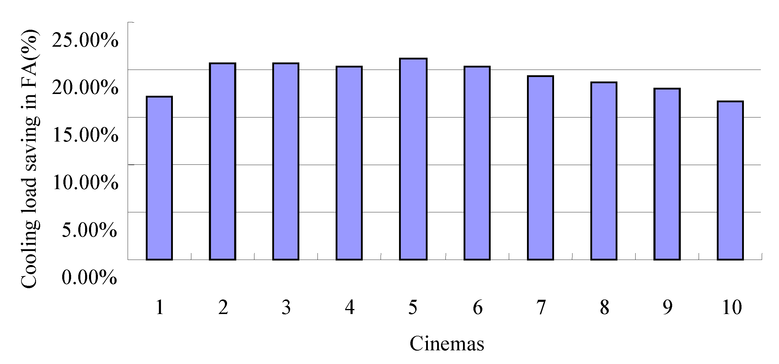
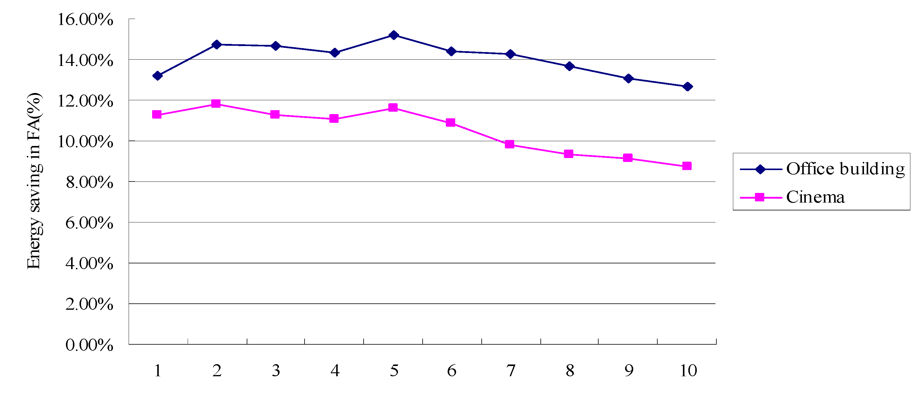
Figure 3 shows the annual reductions for the cooling load in fresh air system per area for the use of HPHX, which is between 31.5 kWh/m
2 and 33.5 kWh/m
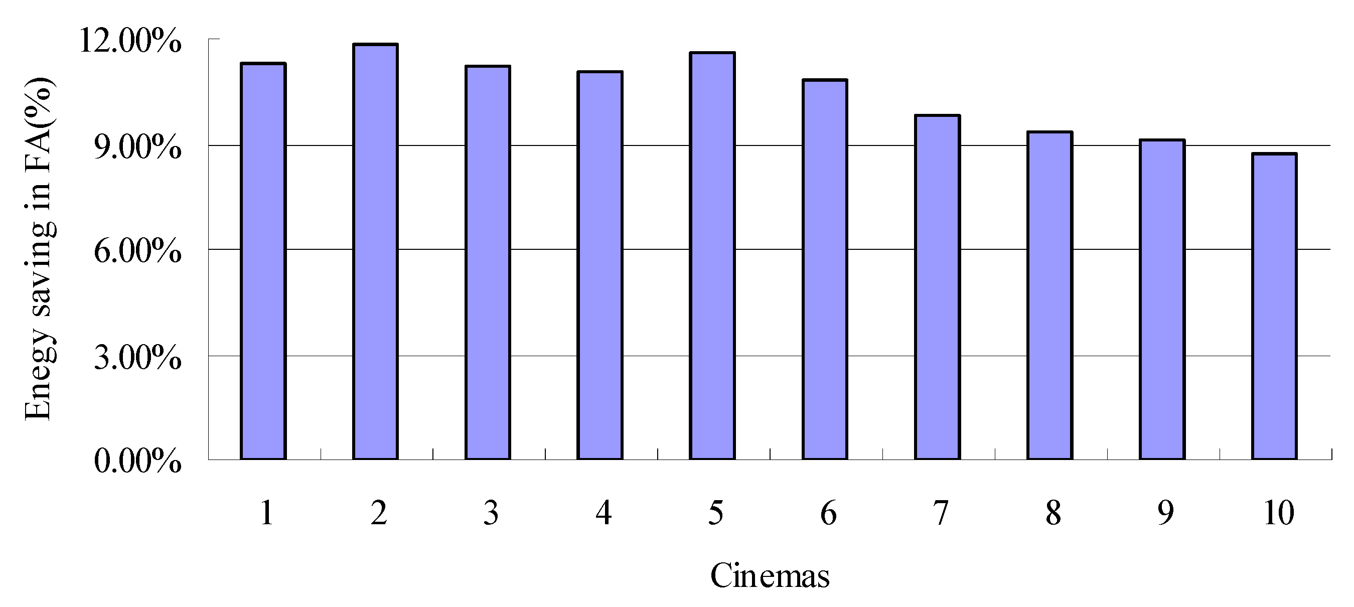
2. The corresponding savings range from 16% to 21%. Considering fresh air contributes to around 30% of the overall consumption for air-conditioning for Southern China [
18], the energy savings can account for approximately 9%–12% of the overall energy use for fresh air system.
Figure 3.
Cooling load saving percentage in fresh air system.
Figure 3.
Cooling load saving percentage in fresh air system.
Figure 4.
Energy saving percentage in fresh air system.
Figure 4.
Energy saving percentage in fresh air system.
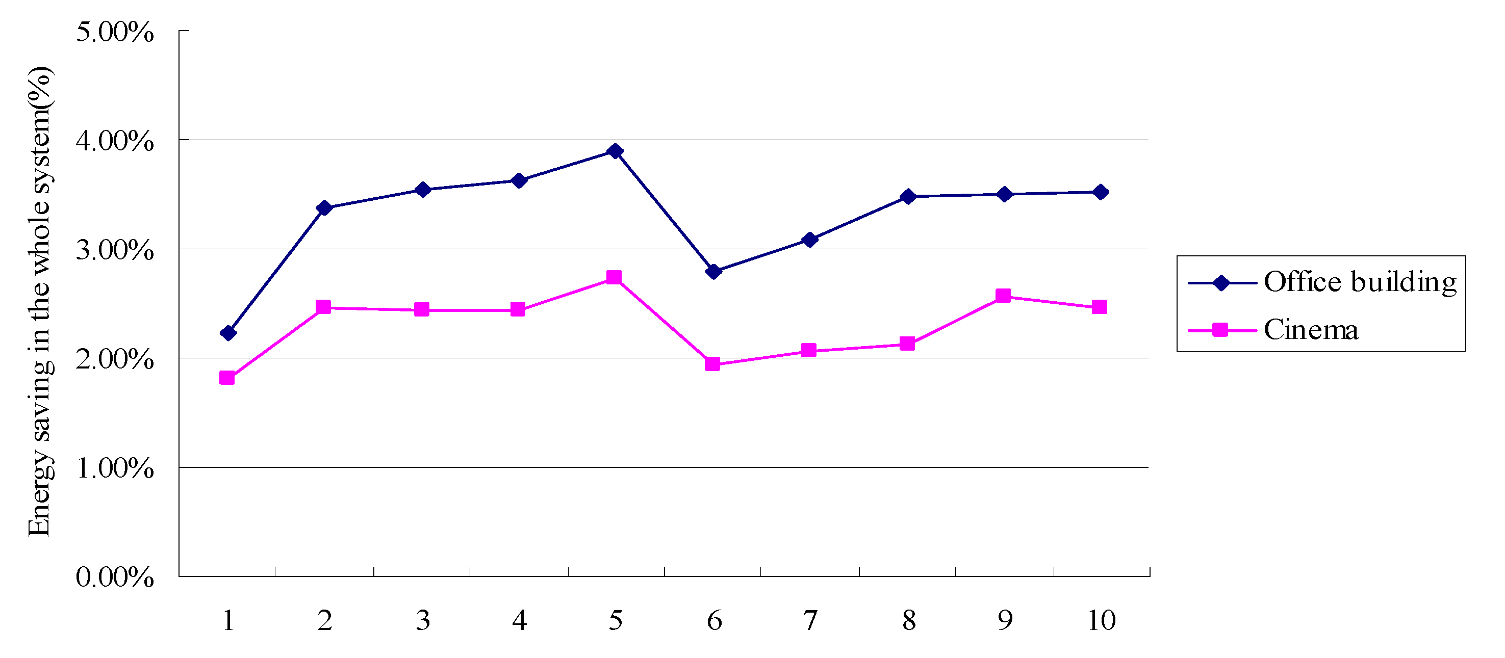
The overall energy saving potential of the whole system can be estimated by the use of Equations (20)–(22). The corresponding savings range from 1.8% to 2.8%. The results are summarized in
Figure 5. The results confirm the feasibility of using HP technology in hot and humid climates like Southern China for buildings.
Figure 5.
Overall energy saving percentages in the whole system.
Figure 5.
Overall energy saving percentages in the whole system.
5.3. Comparison of the Dedicated System with HPHX for Different Buildings
The use of a heat pipe heat exchanger (HPHX) at the air handler dedicated for outdoor treatment to achieve the decoupling for air-conditioning of office environments in Hong Kong has been confirmed effective in an earlier study by the authors [
19]. In this part, the differences between the results for the cinema and the office building based on the same outdoor and indoor conditions will be compared.
Figure 6,
Figure 7 and
Figure 8 show the difference between the cinema and the office building.
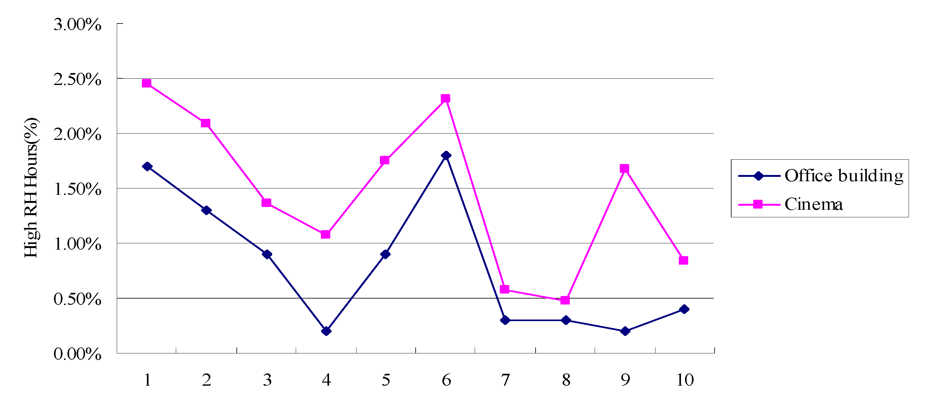
Figure 6 shows that for the cinema the time that the dried and cooled fresh air generated from the HVAC system with HPHX cannot be used to completely remove the space latent load is longer than for the office building system. The maximum is 2.24% and the minimum is 0.35% for the same design conditions. The energy saving potential is weaker than the office building system for the same design conditions. These results are mainly because of the larger windowless rooms in the cinema and the occupancy of the cinema changes greatly which leads to the maximum fresh air load being at the same time. Nevertheless, dedicated ventilation systems combined with heat pipe heat exchangers for dehumidification improvement also work better for cinemas in subtropical area.
Figure 6.
The percent of high RH hours between a cinema and an office building.
Figure 6.
The percent of high RH hours between a cinema and an office building.
Figure 7.
The energy savings in FA between the cinema and the office building.
Figure 7.
The energy savings in FA between the cinema and the office building.
Figure 8.
The energy saving in the whole system between the cinema and the office building.
Figure 8.
The energy saving in the whole system between the cinema and the office building.
6. Experimental
6.1. The Experimental Set-Up
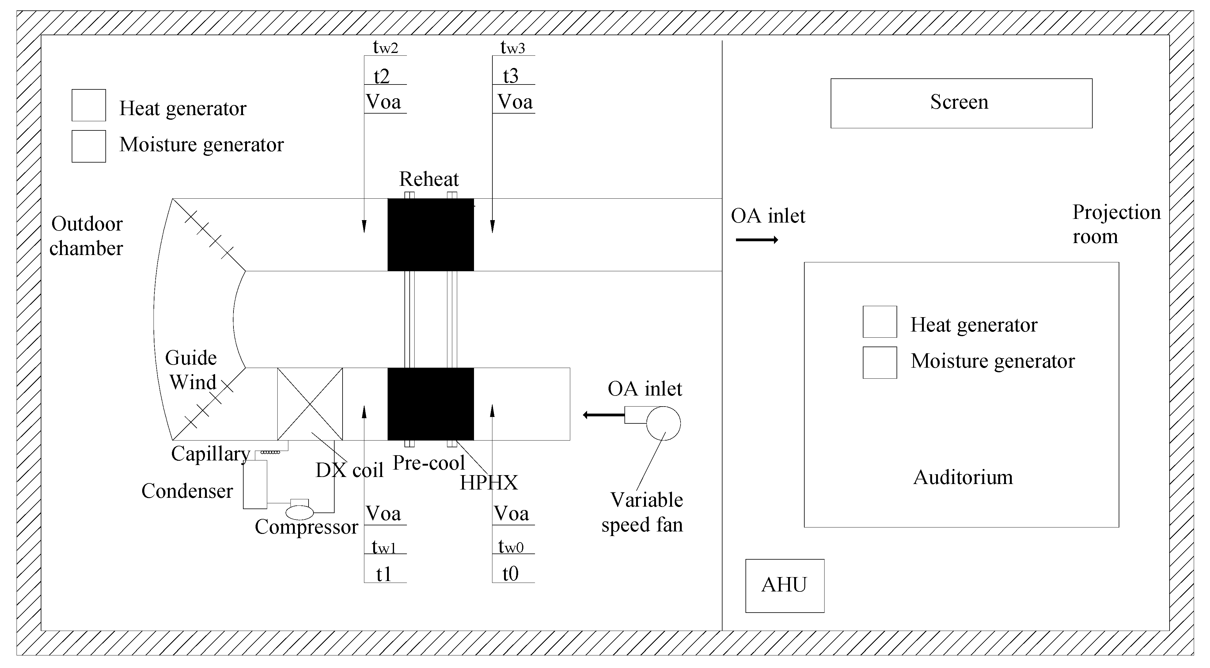
A prototype HPHX-DX was designed and constructed for experimental studies to evaluate the overall performance. The prototype comprises a vertical HP heat exchanger, a variable speed fan, insulated ductwork and a DX coil which will be the evaporator side of a domestic air conditioner of 3.36 kW nominal cooling capacity and 1.4 kW power consumptions as shown in
Figure 9. The air flow rate is adjustable by a variable speed fan installed in the ductwork.
Figure 9.
The experimental set-up. OA—Outdoor Air; AHU—Air Handling Unit; DX coil—Direct Expansion A/C coil; HPHX—Heat Pipe Heat Exchanger.
Figure 9.
The experimental set-up. OA—Outdoor Air; AHU—Air Handling Unit; DX coil—Direct Expansion A/C coil; HPHX—Heat Pipe Heat Exchanger.
6.2. The Experimental Test
The performance of the prototype will be tested in two completely isolated and insulated chambers as shown in
Figure 9, whereby one resembles the outdoor conditions whilst the other represents the space conditions. In the space, Proportion Integration Differentiation (PID) control is adopted to maintain a constant cooling output from the air-handler, and to adjust outputs of the heat and moisture generators to maintain the space conditions.
To keep the air-conditioner working continuously even at low load conditions, the space conditions were purposely set at 22 °C and 50% RH. The maximum outdoor temperatures follow the maximum coincident dry-bulb (35 °C) and wet-bulb temperatures (RH = 80%). The thermal conditions of the space and outdoor chambers and the space heat output during the experiments are summarized in
Table 2.
Table 2.
Controlled conditions during experiments.
Table 2.
Controlled conditions during experiments.
| Conditions | Abbreviation | Varied range |
|---|
| Outdoor chamber | To | 25 to 35 °C at 5 °C intervals |
| RHo | 50% to 80% at 10% intervals |
| Leaving Air Temperature | T3 | 18 °C to 21 °C at 1 °C intervals |
| Airflow Rate | VOA | 0.1; 0.2 and 0.3 m3/s |
For the HVAC system which is the focus of the broader scope of this research, it is the outdoor air condition that would be experienced directly by the HPHX evaporator. Consequently, in order to obtain relevant performance data for a HPHX in this environment, it is necessary to cover a range of dry-bulb temperature (DBT) and RH values appropriate to the Southern China climate. The general climatic conditions of Southern China are mostly extremely hot and humid with an average dry-bulb temperature (DBT) at 20–35 °C and RH of 35%–80%. At the same time it is considered necessary to explore a range of coil face velocities representative of those which might typically occur in practice. Thus, for this series of experiments, runs are performed as follows, with each of the four experimental variables altered one at a time is summarized in
Table 2.
Because of some difficulties in achieving precise control of these parameters, there is some inevitable departure from run-to-run compared with the target values just listed. Nevertheless, for simplicity in presentation and discussion of the data, runs are grouped according to the above nominal values. Throughout each experiment, the system is allowed to achieve steady-state equilibrium conditions about twenty minutes before data are collected.
For measuring the cooling output, the incoming and leaving air dry-bulb and wet-bulb temperatures will be measured using four pairs of type K thermocouples. The airflow rate will be varied and measured by the use of a thermal anemometer. This is to simulate a varying demand in outdoor air (OA). Control system will be provided to maintain the desired leaving air conditions. Moreover, the compressor, fan power consumption will be calculated using the measured running current and supply voltage. All thermometers and flow meters will be connected to two data loggers. The cooling and dehumidification capacity will be determined by energy balance using the measured air flow rate, and the incoming and leaving air temperatures and humidity. The accuracy of the major instruments is summarized in
Table 3.
Table 3.
Accuracy of major instruments.
Table 3.
Accuracy of major instruments.
| Parameter | Abbreviation | Instrument | Type | Manufacturer | Origin | Range and Unit | Accuracy |
|---|
| Temperature | t and tω | Type K thermocouples | YH-KA1 | YuHua | JiangSu, China | −50 to 100 °C | ±(0.05%rdg + 0.5 °C) |
| Airflow Rate | VOA | Thermal anemometer | TL-VII | TianLong | ZheJiang, China | 0–5 m3/s | ±2% |
| Power | W | Power meter | HZ-7330 | HangZhen | TianJin, China | 0 to 1 × 10⁶ A (a.c) | ±(0.25%rdg + 0.05%F.S.) |
6.3. The Experimental Descriptions
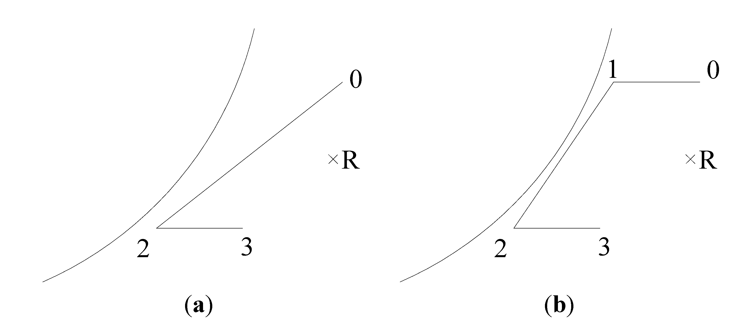
Figure 10 shows the psychometric process of the conventional and the proposed HPHX-DX systems. In the conventional system, the outdoor air (OA) cooled and dehumidified from state 0 to state 2 by a DX coil. At this temperature air could not be directly supplied to the space in order to prevent cold-drafts and over-cooling that would cause discomfort. As a result, supply air is subsequently reheated (state 3) before being distributed into the conditioned space. For the proposed HPHX-DX system, a HP heat exchanger will be adopted to pre-cool OA which is shown in
Figure 10b, Outdoor air OA will be pre-cooled by the evaporator side of heat pipe heat exchanger (state 0 to state 1) and Pre-cooled air further cooled and dehumidified by the DX coil (state 1 to state 2). The cooled air subsequently re-heated by the condenser side of the HP heat exchanger (state 2 to state 3). The conditioned air which is dried and cooled OA will be supplied to the space (state R) with an optimum condition to offset the space latent load and part of the space sensible load in achieving the desired space conditions.
Figure 10.
The psychrometric processes: (a) conventional system; (b) The proposed HPHX-DX system.
Figure 10.
The psychrometric processes: (a) conventional system; (b) The proposed HPHX-DX system.
7. Relevant Theory and Calculation for Experimental
7.1. Theory
Experiments have been used to ascertain every achievable air condition suitable for the building, so as to compare the energy saving potential between conventional system and the proposed system for the same outdoor and space air conditions. In determining the moist air properties, the following perfect gas equations are used:
where:
pws = saturation pressure, Pa;
T = absolute temperature, K;
ωs = humidity ratio of moist air saturated, kg/kg;
ω = humidity ratio, kg/kg;
B = total pressure, 101.325 kPa;
t = dry-bulb temperature, °C;
tω = wet-bulb temperature, °C;
h = moist air specific enthalpy, kJ/kg.
The coefficients
C1 to
C6 were obtained from ASHRAE Handbook. HPHX effectiveness (η
HP) is defined by the Equations (4)–(7) and (23)–(26). The outdoor air conditions (state 0) refer to the experimental conditions in
Table 2.
The overall effectiveness of the HPHX (ηHP) for various experimental conditions was calculated according to Equations (4)–(7) and (23)–(26). It is noted that ηHP varied between 24.3% and 63%. For the experimental, the higher (ηHP = 60%) was chosen in this paper.
7.2. Calculation
The space of the building must have a thermal dynamic steady state all the time in this experiment, namely:
where:
QAHU(t) = cooling load from AHU at time (t), kW;
QOA(t) = cooling load from outdoor air at time (t), kW;
QH(t) = heating load from the heat and moisture generators at time (t), kW; the heat generator is from 0 to 12 kW and the moisture generator is from 0 to 4.8 kW.
For the proposed system (
i.e., within HPHX), OA was conditioned by the HPHX and DX unit before supply to the space. Cooling output of the DX unit can be represented by:
where
hset = space air enthalpy (22 °C, 50%) per s, kJ/kg.
In the space, the steady state is adjusted by the PID whilst the outdoor chamber is adjusted by the manual method. As QAHU(t) and QH(t) were automatically measured and stored in the built-in computer of the environmental chamber, and QOA(t) were determined by energy balance calculations, Equation (27) was adopted to check accuracy of the experimental data for subsequent analysis.
For the conventional system (
i.e., without HPHX), OA is conditioned just by the DX unit before supply to the space. Cooling output of the DX unit can be represented by:
where
QOA(
t)' = cooling load from outdoor air at time (
t) for the conventional system, kW.
Combining Equations (28) and (29), the saving in reheating load is therefore:
Thus, the energy saving potential (ε
AC) for the adoption of the proposed system can be estimated as:
where
QH(
t)' = heating load from the heat and moisture generators at time (
t) for the conventional system, kW.
8. HP Effectiveness and Energy Saving Estimation
8.1. HP Effectiveness
To evaluate if the outdoor air dry-bulb (DB) (
To), RH (
RHo) and
VOA would affect the overall effectiveness of the HPHX, the η
HP at different
To,
RHo and
VOA were analyzed and compared. Results are shown in
Figure 11,
Figure 12 and
Figure 13.
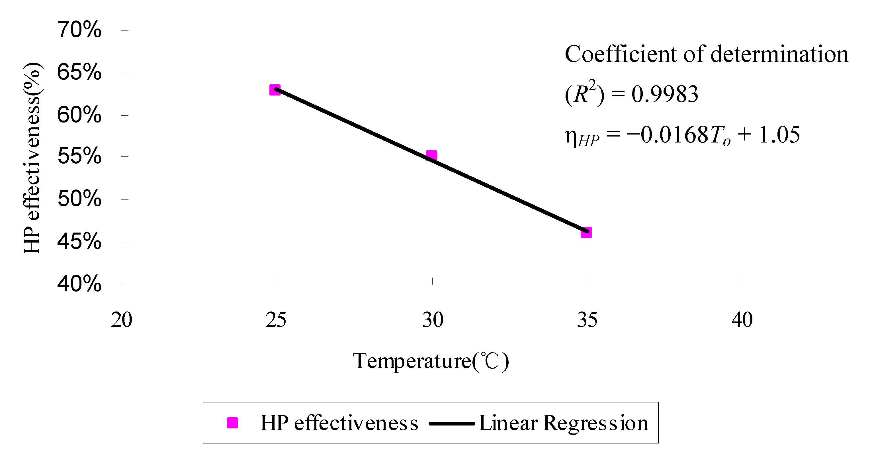
Figure 11.
HP effectiveness of various temperature.
Figure 11.
HP effectiveness of various temperature.
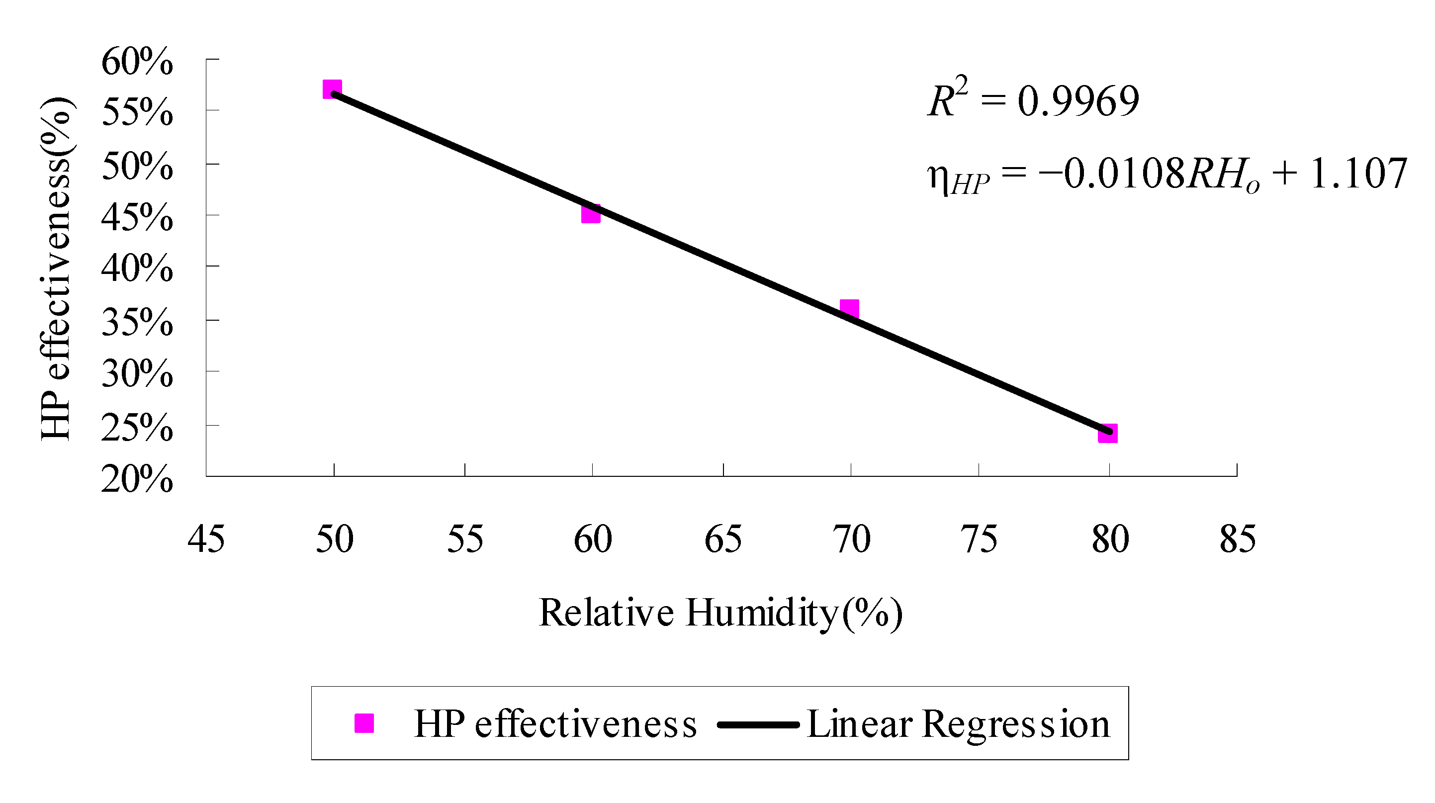
Figure 12.
HP effectiveness of various RH.
Figure 12.
HP effectiveness of various RH.
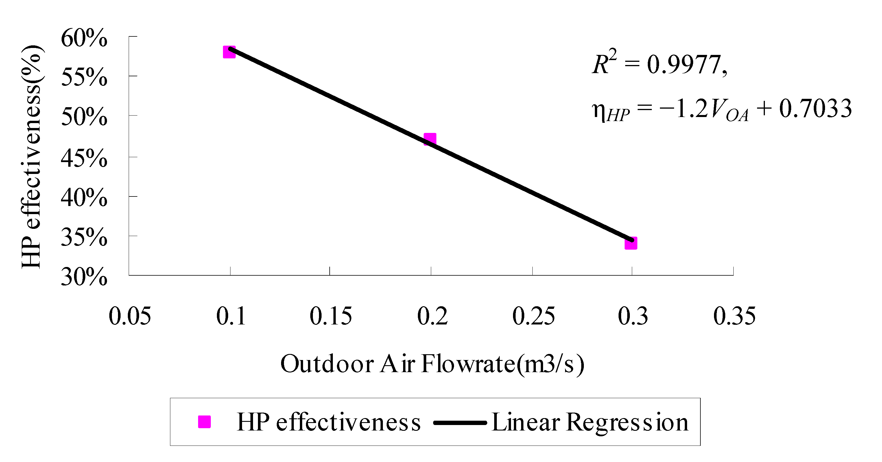
Figure 13.
HP effectiveness of various Airflow rate.
Figure 13.
HP effectiveness of various Airflow rate.
It can be seen that various outdoor conditions (To; RHo and VOA) affect the HP effectiveness, and the correlation between outdoor conditions (To; RHo and VOA) and HP effectiveness can be regressed into a straight line. The high correlation level indicates that ηHP increased with a decrease of To; RHo and VOA, namely 25 °C, 50%, 0.1 m3/s with the highest ηHP.
According to the regression estimates, the correlation between outdoor conditions (
To;
RHo and
VOA) and HP effectiveness can be regressed to one straight line. It is noted that they exhibit a linear relationship, and the regressed model is:
The coefficient of determination (R2) of this model was found to be 0.7902 to show a strong linear correlation at the 95% confidence level.
8.2. Energy Saving Estimation
The use of HPHX-DX system can reduce OA cooling load as well as the reheating load, which can be estimated by the use of the equations given in this paper. From the experimental data, the space conditions were maintained by adjusting the output of the heat generator and moisture generator through PID when estimating the energy saving potential.
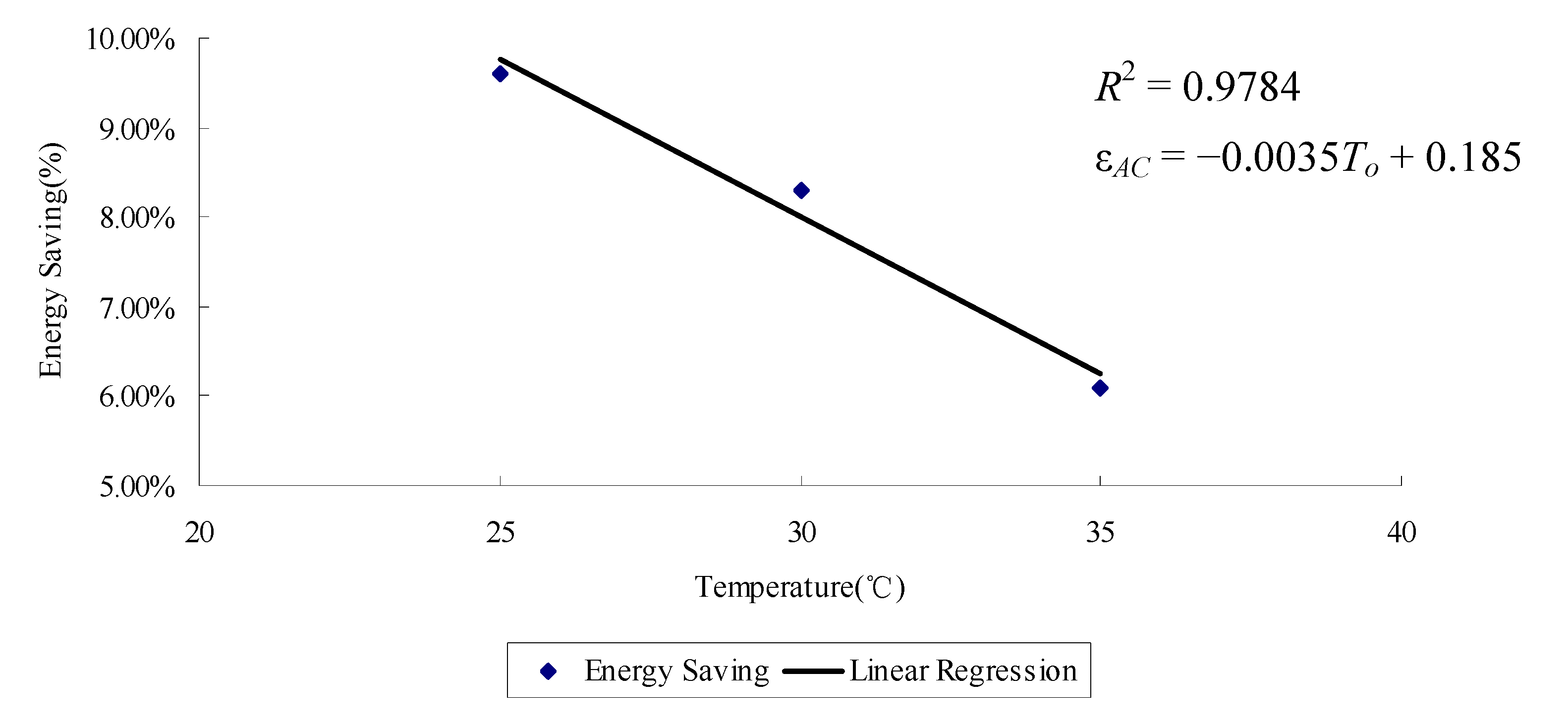
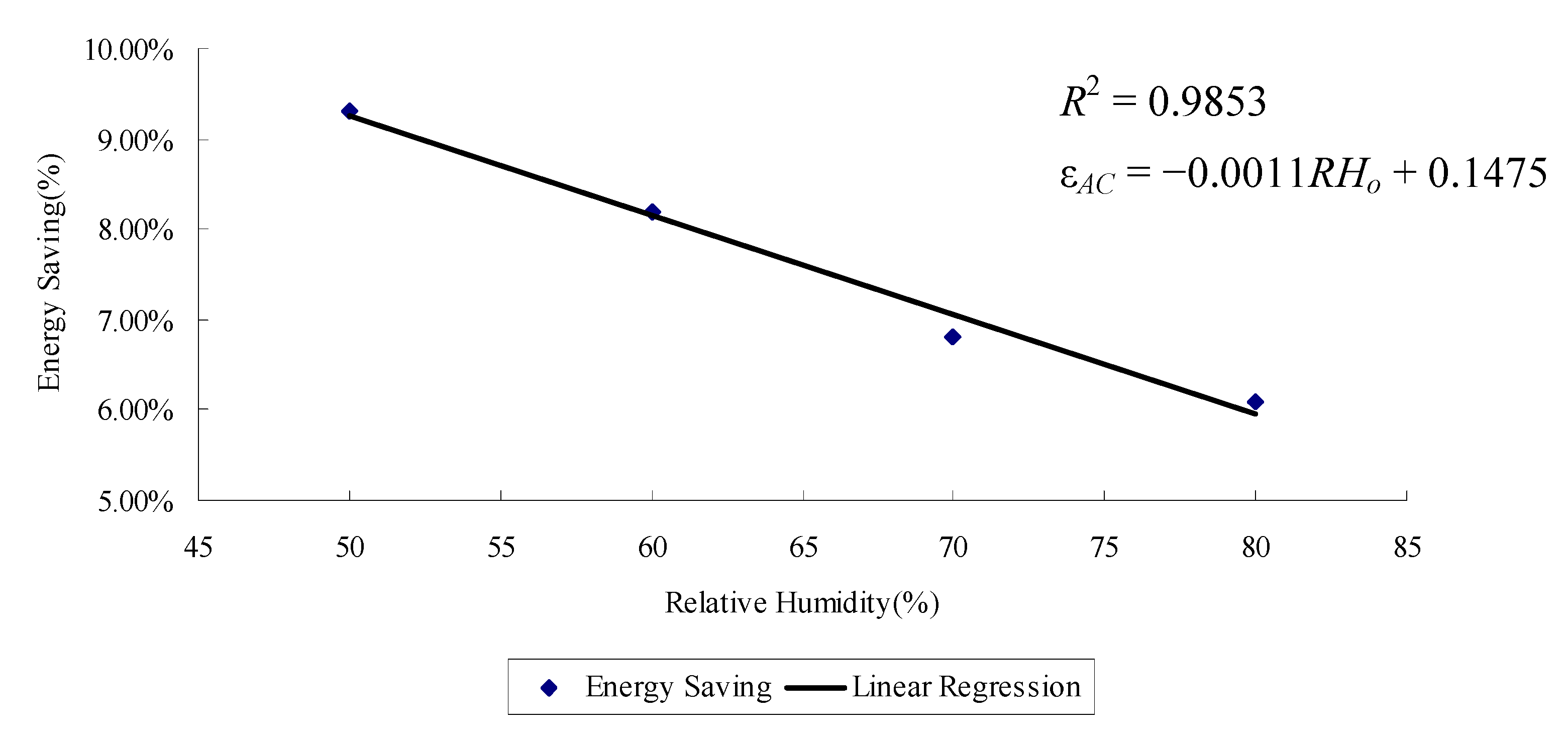
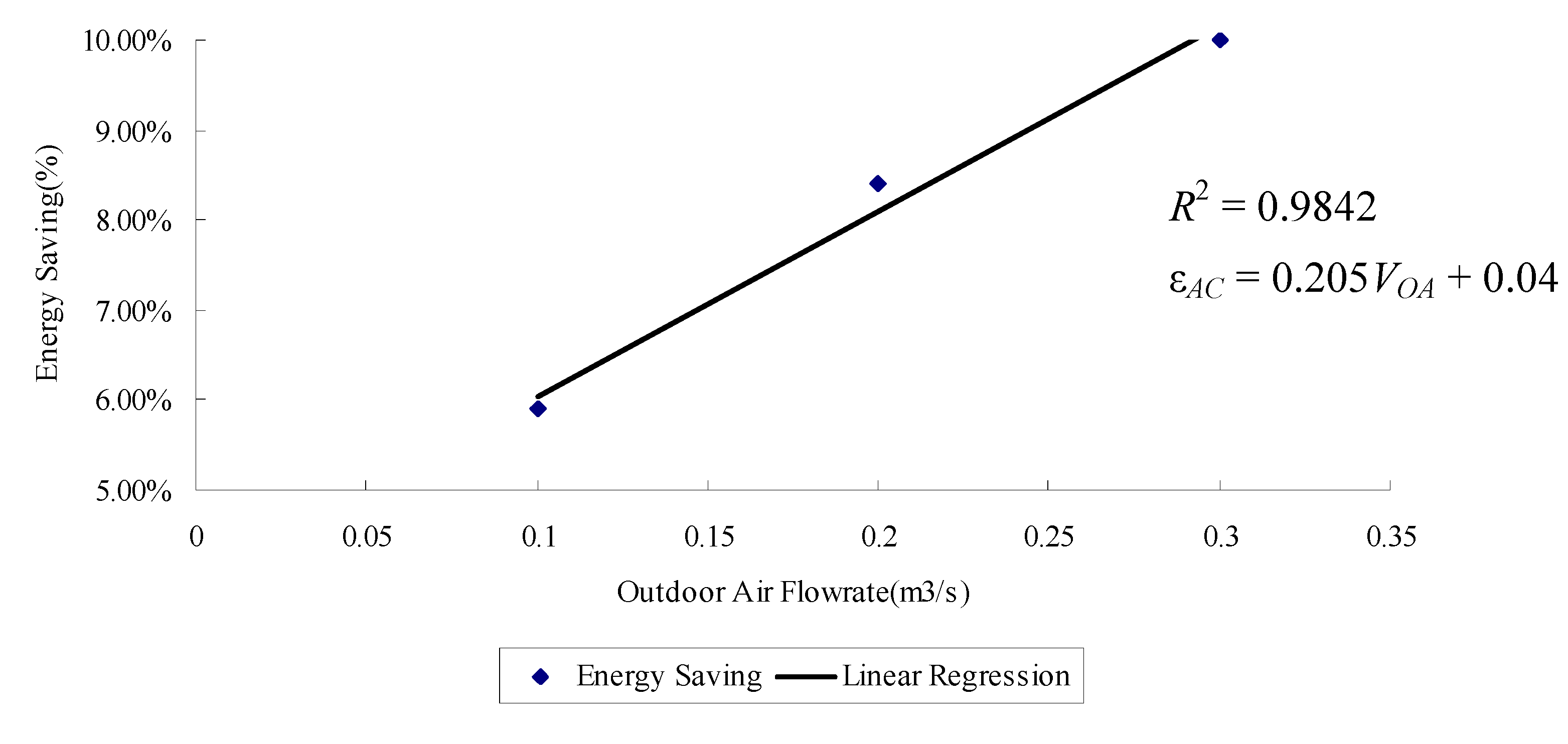
The ε
AC under different outdoor conditions (
To,
RHo and
VOA) were discussed and compared. Results are shown in
Figure 14,
Figure 15 and
Figure 16. The correlation between outdoor conditions (
To;
RHo and
VOA) and energy saving can also be regressed to a straight line. To explain the influence of each complex parameter, it can be seen that for different
To and
RHo values, η
HP and ε
AC have the same trend which increased with a decrease of
To;
RHo, while for the influence of
VOA, it is evident from Equations (30) and (31) that q higher
VOA would return a higher ε
AC.
It is evident that the outdoor condition (
To;
RHo and
VOA) and energy saving can also be regressed to a linear relationship, and the model is:
The coefficient of determination (R2) of the model was found to be 0.8629, which shows a high level of correlation at the 95% confidence level.
Figure 14.
Energy saving potential of various temperature.
Figure 14.
Energy saving potential of various temperature.
Figure 15.
Energy saving potential of various RH.
Figure 15.
Energy saving potential of various RH.
Figure 16.
Energy saving potential of various Airflow rate.
Figure 16.
Energy saving potential of various Airflow rate.
9. Conclusions
In order to evaluate HP effectiveness and energy savings potential of a HPHX-DX system when it is applied in Southern China, two systems have been designed, simulated, and evaluated with the HP effectiveness of 0.6. The annual cooling load profiles of 10 buildings in Southern China have been simulated by the use of HTB2 software. Based on the output of HTB2 and the subsequent evaluations, the main conclusions are: it has been found that out of the annual operating hours of the air-conditioning systems, only 2.45% of the time the dried and cooled fresh air generated from the dedicated ventilation system with HPHX cannot be used to completely remove the space latent load. The savings in cooling load and the reheating load were estimated. They correspond to 9% to 12% of the fresh air system energy use and 1.8% to 2.8% of the overall system energy use for air-conditioning of building in Southern China.
At the same time, an experimental HPHX-DX prototype has been designed and constructed for experimental studies to evaluate the overall performance at different space and outdoor conditions. The experimental results demonstrate that for all cases examined, when the other conditions remained unchanged, HP effectiveness increased with a decrease of outdoor temperature, RH and air flow rate. For different outdoor temperature and RH values, the HP effectiveness and energy saving potential have the same trend, which increases with a decrease of outdoor temperature and RH, but the energy saving potential increased with an increase of air flow rate. The overall effectiveness of the HPHX (ηHP) for various experimental conditions has been calculated and it was noted that ηHP varied between 24.3% and 63%. The energy saving potential of 6% to 10% for the fresh air system combined with a heat pipe heat exchanger.
The results of this study confirm that in the use of HP technology in hot and humid climates like Southern China, a HPHX-DX system is a feasible way to operate a HVAC system. There are some shortcomings in that the proposed system is more expensive than the conventional system and it is not suitable for frigid and temperate climates. Further theoretical calculations and experiments will be also used in a future work for the feasible use of the proposed HPHX-DX system in other types of buildings (e.g., laboratories, industrial building, etc.).
Author Contributions
Lian Zhang designed the proposed system, conceived the simulation and experimental idea and analyzed the simulation and experimental data, and wrote and revised the manuscript. The methodology and analytic procedures were carried out by Yu-Feng Zhang. Final review, including final manuscript corrections, was also done by Yu-Feng Zhang.
Conflicts of Interest
The authors declare no conflict of interest.
References
- Electrical and Mechanical Services Department. The Hong Kong Energy Efficiency Labelling Scheme for Domestic Appliances; The Hong Kong SAR Government: Hong Kong, China; pp. 1995–2000.
- Mori, Y.H.; Ochiai, J.; Ohmura, R. Using submarine heat pumps for efficient gas production from seabed hydrate reservoirs. Energies 2012, 5, 599–604. [Google Scholar] [CrossRef] [Green Version]
- Peigné, P.; Inard, C.; Druette, L. Ventilation heat recovery from wood-burning domestic flues. A Theoretical Analysis Based on a Triple Concentric Tube Heat Exchanger. Energies 2013, 6, 351–373. [Google Scholar] [CrossRef]
- Huang, H.-J.; Shen, S.-C.; Shaw, H.-J. Design and fabrication of a novel hybrid-structure heat pipe for a concentrator photovoltaic. Energies 2012, 5, 4340–4349. [Google Scholar] [CrossRef]
- Yang, F.; Yuan, X.; Lin, G. Waste heat recovery using heat pipe heat exchanger for heating automobile using exhaust gas. Appl. Therm. Eng. 2003, 23, 367–372. [Google Scholar] [CrossRef]
- Ahmadzadehtalatapeh, M. An air-conditioning system performance enhancement by using heat pipe based heat recovery technology. Sci. Iran. 2013, 20, 329–336. [Google Scholar]
- Srimuang, W.; Amatachaya, P. A review of the applications of heat pipe heat exchangers for heat recovery. Renew. Sustain. Energy Rev. 2012, 16, 4303–4315. [Google Scholar] [CrossRef]
- Yau, Y.H. Application of a heat pipe heat exchanger to dehumidification enhancement in a HVAC system for tropical climates-a baseline performance characteristics study. Int. J. Therm. Sci. 2007, 46, 164–171. [Google Scholar] [CrossRef]
- Yau, Y.H. Experimental thermal performance study of an inclined heat pipe heat exchanger operating in high humid tropical HVAC systems. Int. J. Refrig. 2007, 30, 1–10. [Google Scholar] [CrossRef]
- Yau, Y.H. The use of a double heat pipe heat exchanger system for reducing energy consumption of treating ventilation air in an operating theatre—A full year energy consumption model simulation. Energy Build. 2008, 40, 917–925. [Google Scholar] [CrossRef]
- Yau, Y.H.; Ahmadzadehtalatapeh, M. A review on the application of horizontal heat pipe heat exchangers in air conditioning systems in the tropics. Appl. Therm. Eng. 2010, 30, 77–84. [Google Scholar] [CrossRef]
- Ahmadzadehtalatapeh, M.; Yau, Y.H. The application of heat pipe heat exchangers to improve the air quality and reduce the energy consumption of the air conditioning system in a hospital ward—A full year model simulation. Energy Build. 2011, 43, 2344–2355. [Google Scholar] [CrossRef]
- Alexander, D.K. HTB2—A Model for the Thermal Environment of Building in Operation; Welsh School of Architecture Research and Development, University of Wales College of Cardiff: Cardiff, UK, 1994. [Google Scholar]
- Alexander, D.K. HTB2 User Manual Version; Welsh School of Architecture R&D, University of Wales College of Cardiff: Cardiff, UK, 1997. [Google Scholar]
- Performance Catalogue of Heat Pipe, Beijing Tip Top Energy-saving equipment Co., Ltd., Beijing, China. Available online: http://www.jnjn.net/index.html (accessed on 18 February 2014).
- Performance Catalogue of Heat Pipe, Harbin down Happy Heat Pipe Technology Inc., Harbin, China. Available online: http://www.heatpipe.net.cn (accessed on 27 January 2014).
- Electrical and Mechanical Services Department. Code of Practice for Energy Efficiency of Air-conditioning Installations; The Hong Kong SAR Government: Hong Kong, China, 1998.
- Lee, W.L.; Yik, F.W.H.; Burnett, J. Simplifying energy performance assessment method in the Hong Kong building environmental method. Build. Serv. Eng. Res. Technol. 2005, 22, 113–132. [Google Scholar]
- Zhang, L.; Lee, W.L. Evaluating the use heat pipe for dedicated ventilation of office buildings in Hong Kong. Energy Convers. Manag. 2011, 52, 1983–1989. [Google Scholar] [CrossRef]
© 2014 by the authors; licensee MDPI, Basel, Switzerland. This article is an open access article distributed under the terms and conditions of the Creative Commons Attribution license (http://creativecommons.org/licenses/by/3.0/).


