Experimental and Numerical Study of Jet Controlled Compression Ignition on Combustion Phasing Control in Diesel Premixed Compression Ignition Systems

Abstract
:1. Introduction
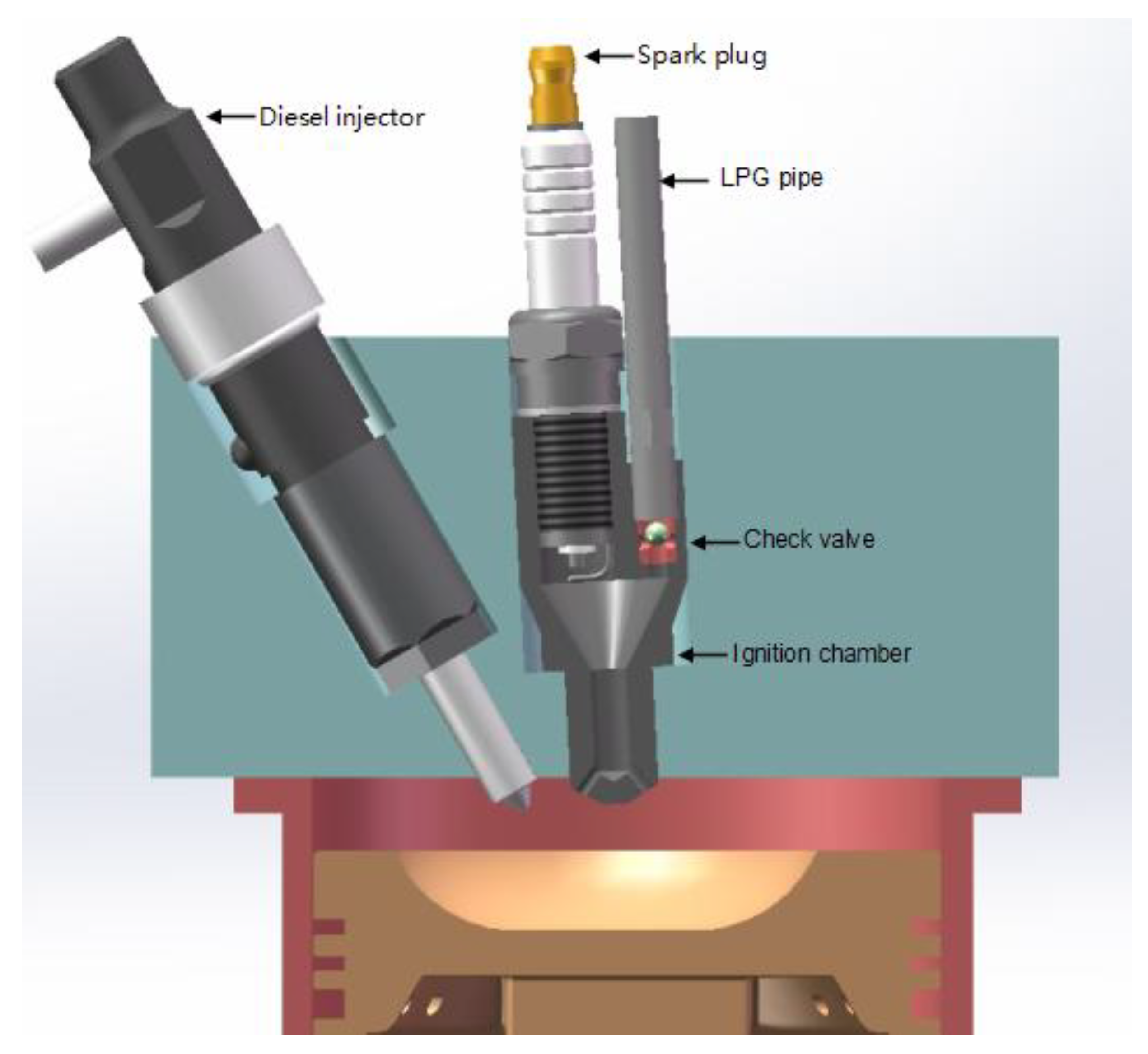
2. The JCCI System
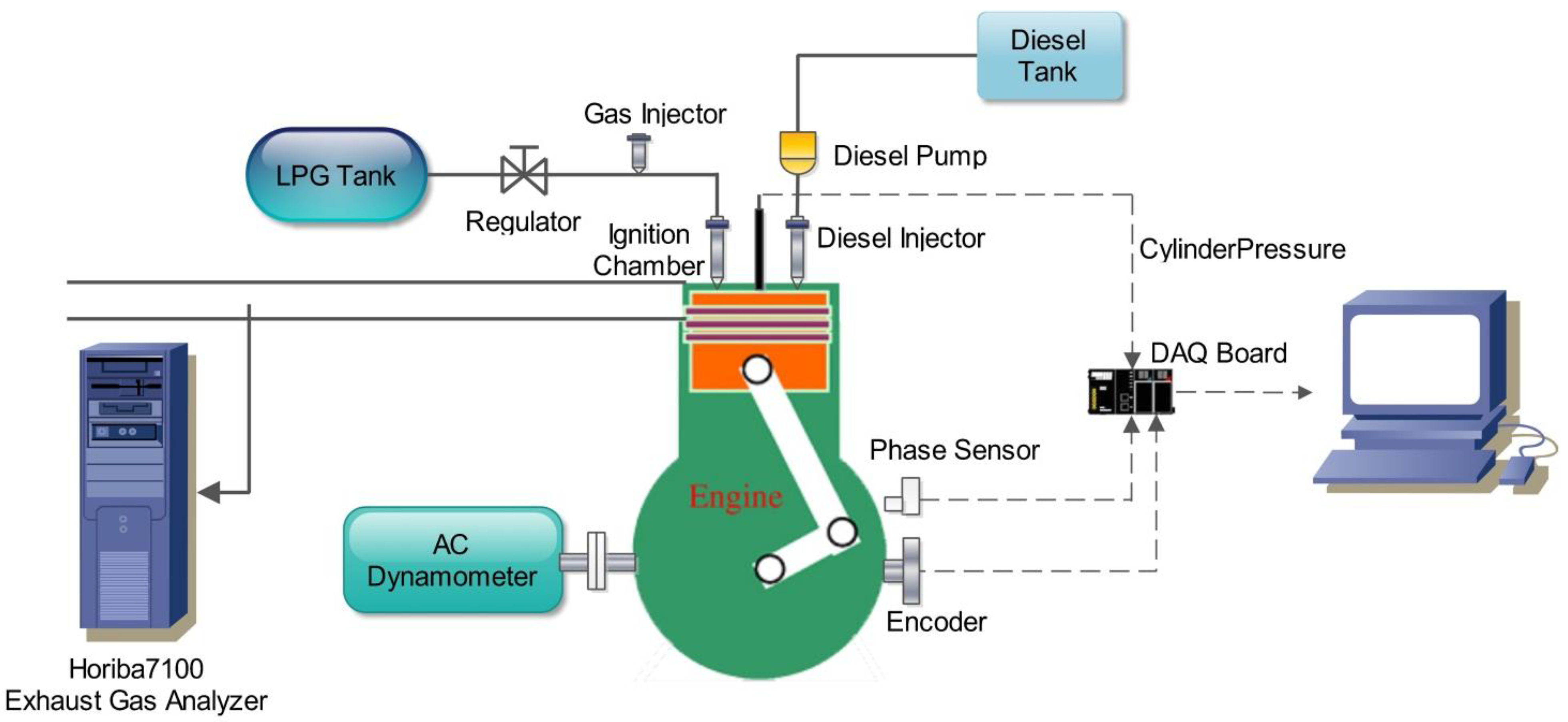
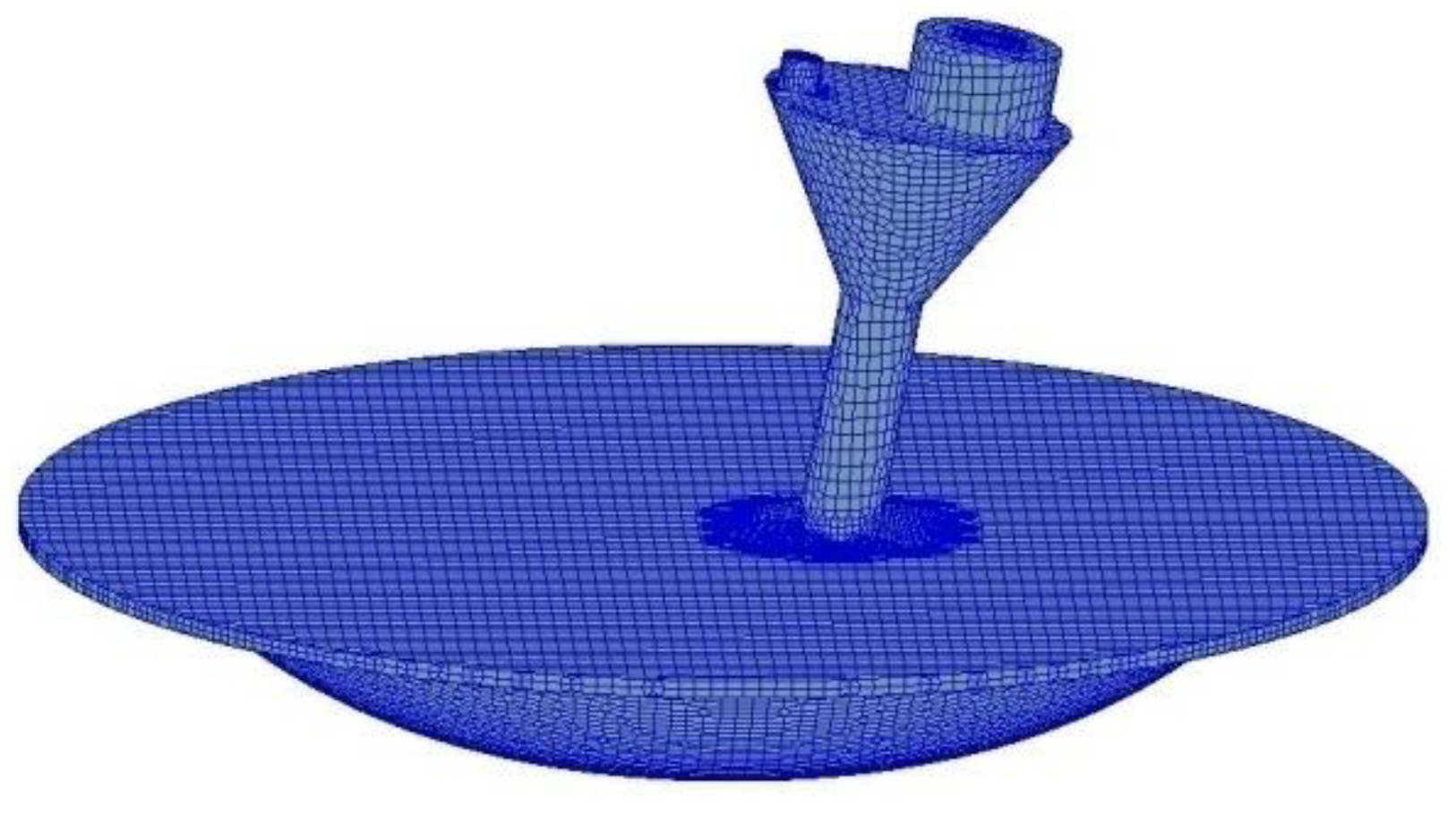
3. Experimental and Numerical Setup


| Engine type | Specifications |
|---|---|
| Bore × stoke | 86 mm × 72 mm |
| Compression ratio | 12 |
| Ignition chamber volume | 1.7 mL |
| Rated speed for diesel engine | 3000 rpm |
| Rated power for diesel engine | 5.68 kW |
| Intake valve opening (IVO) | 8.5° BTDC |
| Intake valve closing (IVC) | 44.5° ABDC |
| Exhaust valve opening (EVO) | 55.5° BBDC |
| Exhaust valve closing (EVC) | 8.5° ATDC |

| Computational setup | Specifications |
|---|---|
| Turbulent model | RNG k–ε model [23] |
| Breakup model | KH-RT model [24] |
| Combustion model | ECFM-3Z model [25] |
| Swirl ratio | 2.5 |
| Intake pressure | 1.01 bar |
| Intake temperature | 293 ± 3 K |
| Cylinder liner temperature | 470 K |
| Cylinder head temperature | 550 K |
| Piston wall temperature | 550 K |
| Ignition chamber wall temperature | 580 K |

| Operating parameters | Specifications |
|---|---|
| Speed | 3000 rpm |
| BMEP | 1.09 bar to 3.27 bar |
| Spark timing | 20° to 5° BTDC |
| Diesel injection timing | 45° BTDC |
| LPG injection timing | 120° BTDC |
4. Results and Discussion
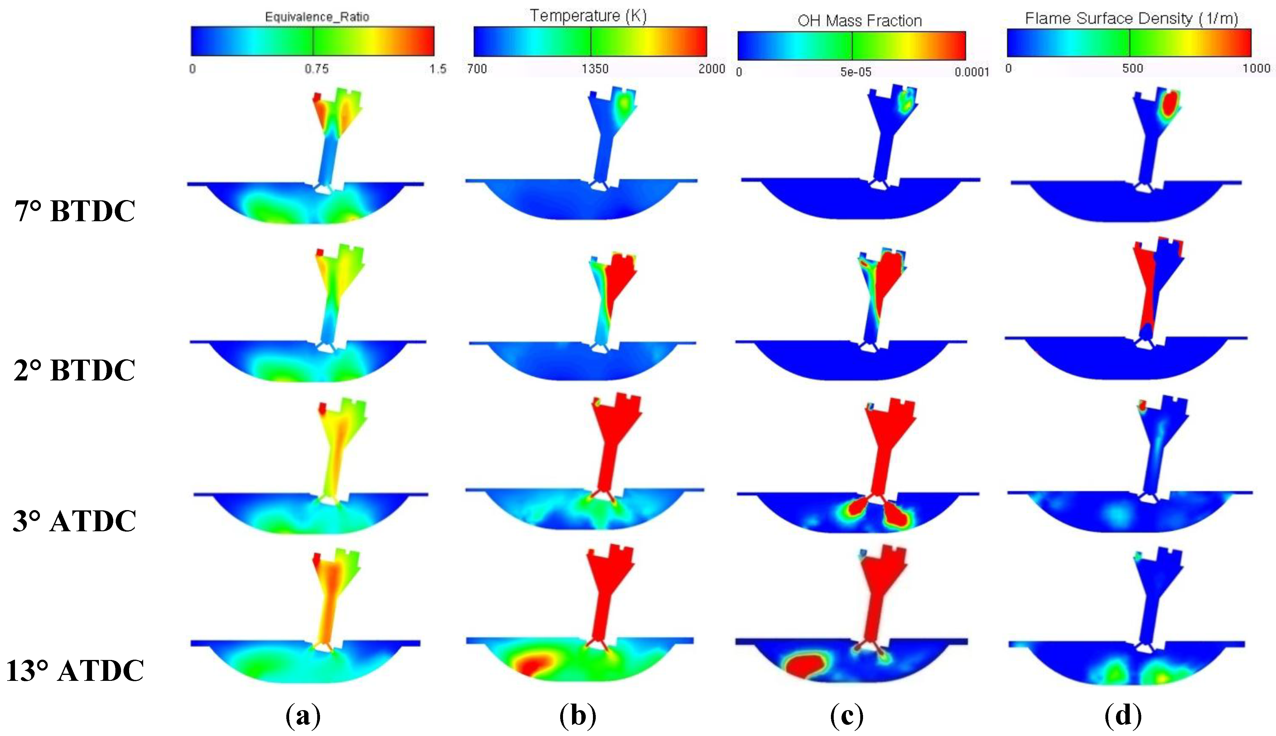
4.1. Numerical Analysis of Ignition Process in JCCI


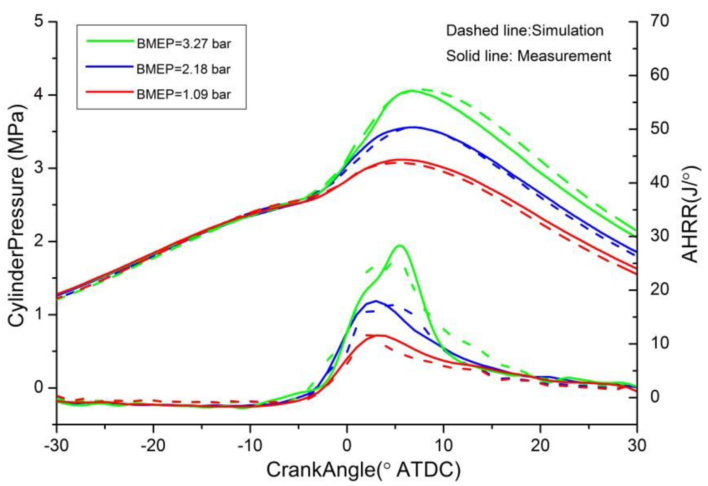
4.2. Analysis of Spark Timing Sweep Experimental Results
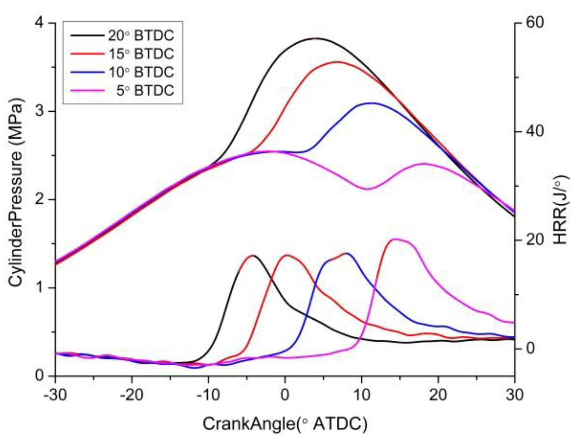
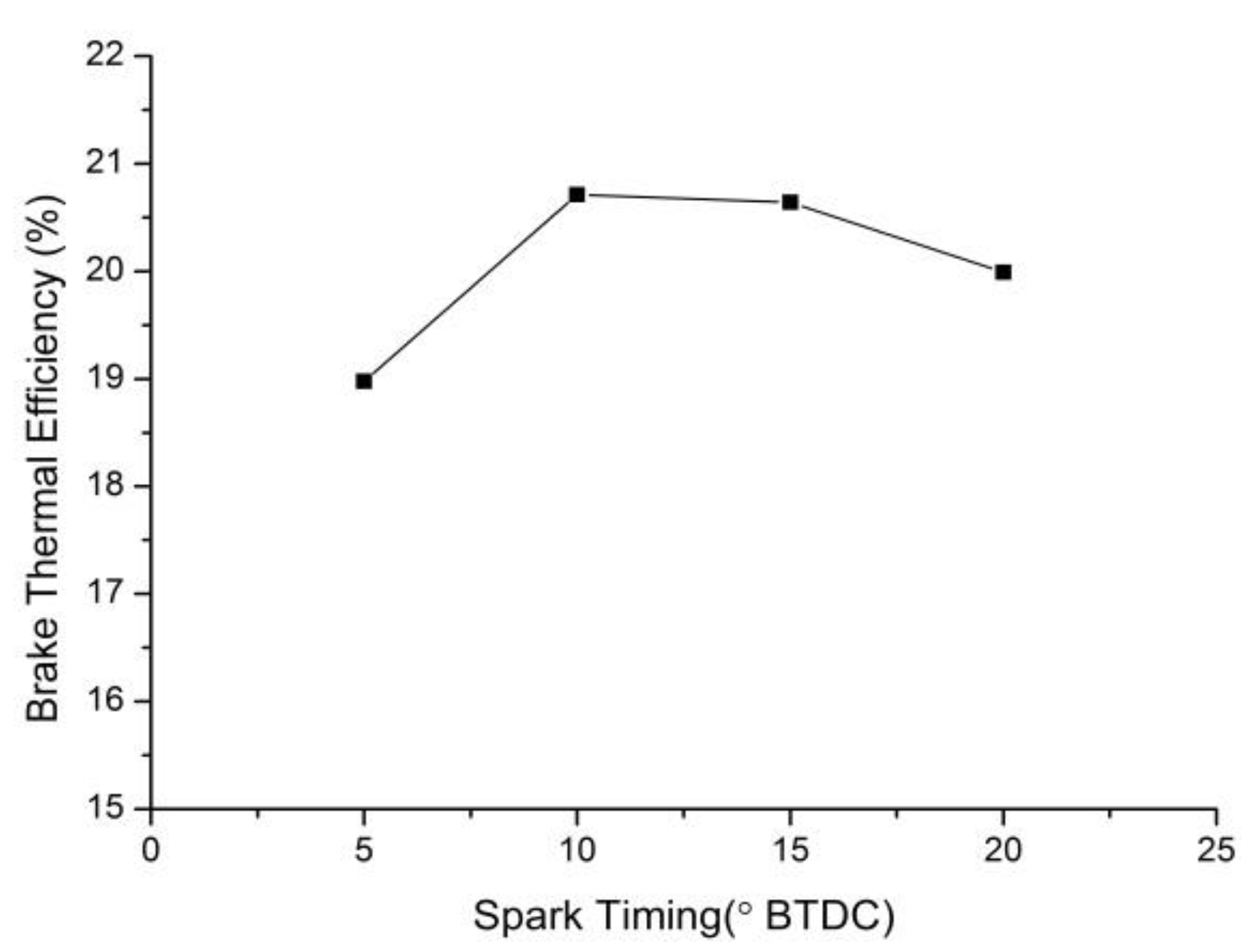
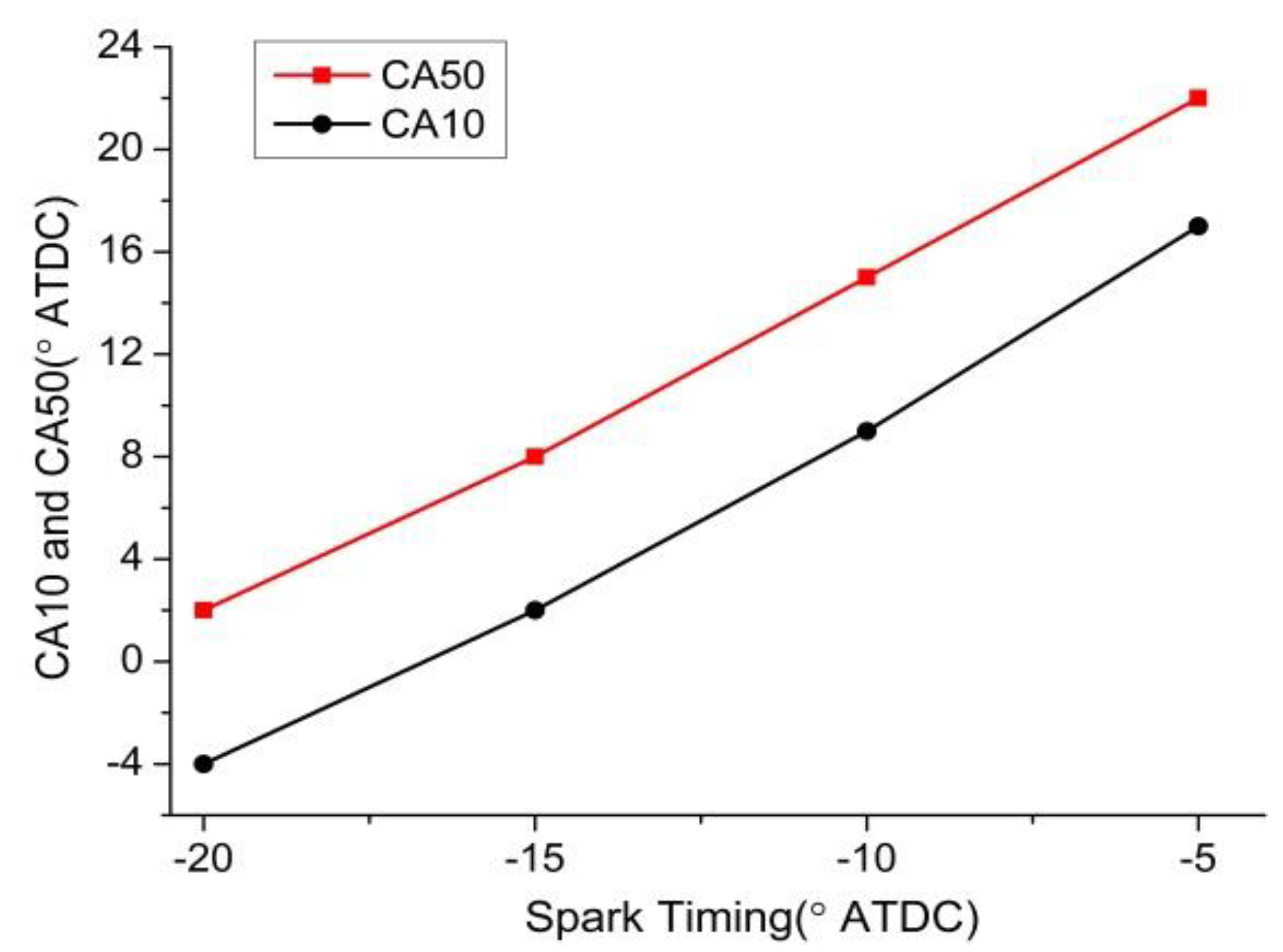
4.2.1. Effects of Spark Timing on Combustion Characteristics


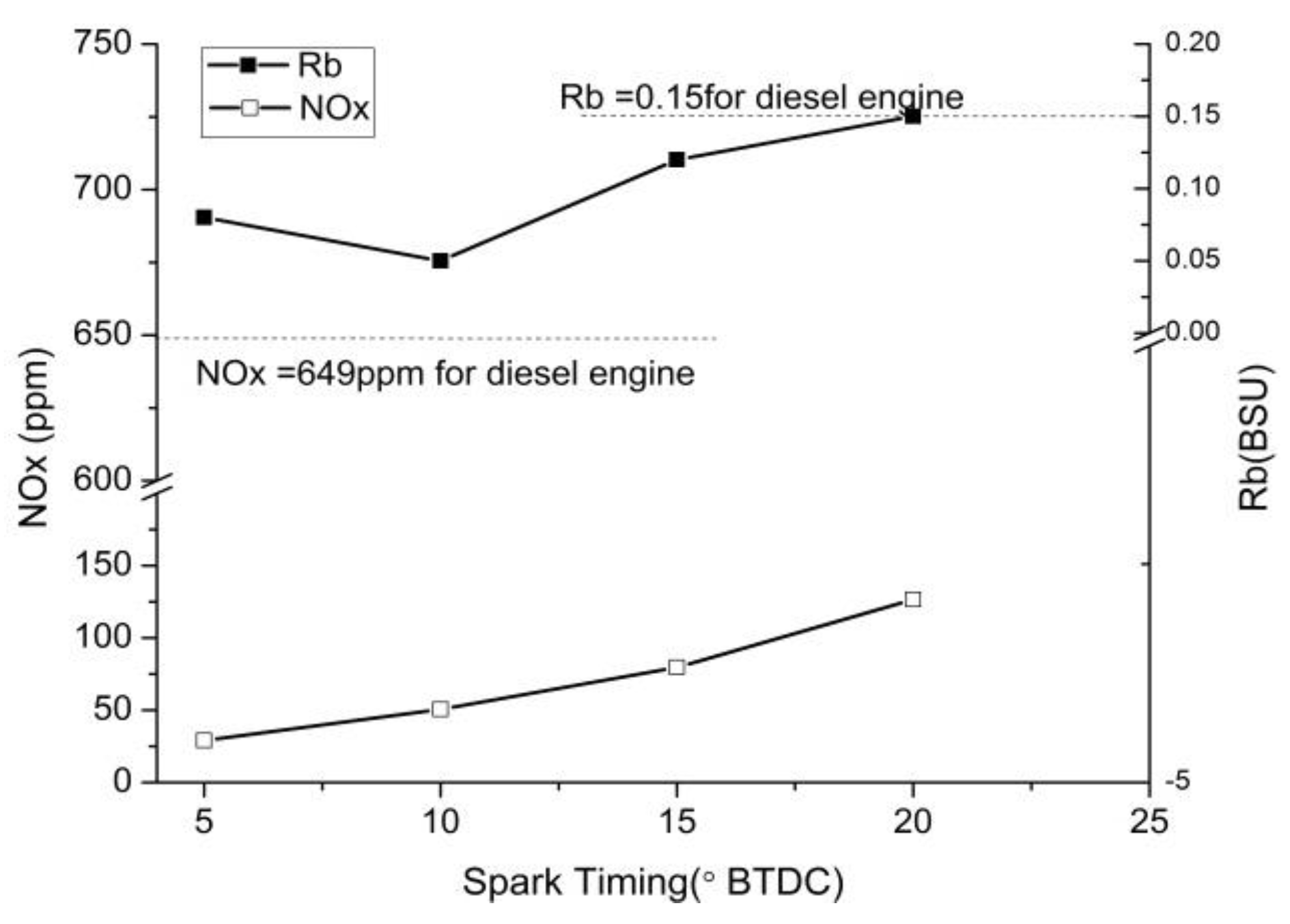
4.2.2. Effects of Spark Timing on Emissions


5. Conclusions
Acknowledgments
Author Contributions
Conflicts of Interest
References
- Hu, G. Prospect on diesel combustion research. J. Dalian Inst. Technol. 1982, 4, 71–80. [Google Scholar]
- Hu, G. New Strategy on Diesel Combustion Development; SAE Technical Paper 900442; SAE International: Warrendale, PA, USA, 1 February 1990. [Google Scholar] [CrossRef]
- Long, W.; Ohtsuka, H.; Obokata, T. Characterization of conical spray flow for diesel engine by means of laser doppler methods: PDA measurement of droplet size distribution. JSME Int. J. Series B Fluids Therm. Eng. 1996, 39, 554–561. [Google Scholar] [CrossRef]
- Leng, X.; Feng, L.; Tian, J.; Du, B.; Long, W.; Tian, H. A Study of the mixture formation process for a third-generation conical spray applied in HCCI diesel combustion. Fuel 2010, 89, 392–398. [Google Scholar] [CrossRef]
- Dumitrescu, C.E.; Neill, W.S.; Guo, H.; Hosseini, V.; Chippior, W.L. Fuel property effects on PCCI combustion in a heavy-duty diesel engine. Am. Soc. Mech. Eng. 2012, 134, 52801–52808. [Google Scholar]
- Stanglmaier, R.H.; Roberts, C.E. Homogeneous Charge Compression Ignition (HCCI): Benefits, compromises, and future engine applications. Prog. Technol. 2003, 100, 477–484. [Google Scholar]
- Luszcz, P.; Xu, H.; Wyzsnski, M.; Ma, X.; Stevens, R.; Tsolakis, A. Imaging studies of in-cylinder HCCI combustion. Front. Energy 2011, 5, 313–321. [Google Scholar]
- Kuboyama, T.; Moriyoshi, Y.; Hatamura, K.; Suzuki, M.; Takanashi, J.; Yamada, T.; Gotoh, S. Effect of fuel and thermal stratifications on the operational range of an HCCI gasoline engine using the blow-down super charge system. SAE Int. J. Engines 2010, 3, 666–680. [Google Scholar]
- Kokjohn, S.; Hanson, R.; Splitter, D.A.; Reitz, R.D. Experiments and modeling of dual-fuel HCCI and PCCI combustion using in-cylinder fuel blending. SAE Int. J. Engines 2009, 2, 24–39. [Google Scholar]
- Benajes, J.; Novella, R.; Garcia, A.; Domenech, V.; Durrett, R. An investigation on mixing and auto-ignition using diesel and gasoline in a direct-injection compression-ignition engine operating in PCCI combustion conditions. SAE Int. J. Engines 2011, 4, 2590–2602. [Google Scholar]
- Eichmeier, J.; Wagner, U.; Spicher, U. Controlling gasoline low temperature combustion by diesel micro pilot injection. J. Eng. Gas Turbines Power 2012, 134, 072802. [Google Scholar] [CrossRef]
- Flowers, D.; Aceves, S.M.; Martinez-Frias, J.; Smith, J.R.; Au, M.; Girard, J.; Dibble, R. Operation of a Four-Cylinder 1.9L Propane Fueled Homogeneous Charge Compression Ignition Engine: Basic Operating Characteristics and Cylinder-to-Cylinder Effects; SAE Technical Paper 2001-01-1895; SAE International: Warrendale, PA, USA, 7 May 2001. [Google Scholar] [CrossRef]
- Jia, M.; Xie, M.; Wang, T.; Peng, Z. The effect of injection timing and intake valve close timing on performance and emissions of diesel PCCI engine with a full engine cycle CFD simulation. Appl. Energy 2011, 88, 2967–2975. [Google Scholar] [CrossRef]
- Kim, D.S.; Lee, C.S. Improved emission characteristics of HCCI engine by various premixed fuels and cooled EGR. Fuel 2006, 85, 695–704. [Google Scholar] [CrossRef]
- Park, Y.; Bae, C. Influence of EGR and Pilot Injection on PCCI Combustion in a Single-Cylinder Diesel Engine; SAE Technical Paper2011-01-1823; SAE International: Warrendale, PA, USA, 30 August 2011. [Google Scholar] [CrossRef]
- Murase, E.; Hanada, K. Control of the Start of HCCI Combustion by pulsed flame jet; SAE Technical Paper 2002-01-2867; SAE International: Warrendale, PA, USA, 21 October 2002. [Google Scholar] [CrossRef]
- Kyaw, Z.H.; Watson, H.C. Hydrogen assisted jet ignition for near elimination of NOx and cyclic variability in the S.I. Engine. Symp. Int. Combust. 1992, 24, 1449–1455. [Google Scholar] [CrossRef]
- Gussak, L.A.; Michael, C.T.; Donald, C.S. High Chemical Activity of Incomplete Combustion Products and a Method of Prechamber Torch Ignition for Avalanche Activation of Combustion in Internal Combustion Engines; SAE Technical Paper 750890; SAE International: Warrendale, PA, USA, 1 February 1975. [Google Scholar] [CrossRef]
- Gussak, L.A.; Karpov, V.P.; Tikhonov, Y.V. The Application of Lag-Process in Prechamber Engines; SAE Technical Paper 790692; SAE International: Warrendale, PA, USA, 1 February 1979. [Google Scholar] [CrossRef]
- Attard, W.P.; Neil, F.; Patrick, P.; Toulson, E. A turbulent jet ignition pre-chamber combustion system for large fuel economy improvements in a modern vehicle powertrain. SAE Int. J. Engines 2010, 3, 20–37. [Google Scholar]
- Attard, W.P.; Michael, B.; Patrick, P.; Blaxill, H. A New Combustion System Achieving High Drive Cycle Fuel Economy Improvements in a Modern Vehicle Powertrain; SAE Technical Paper 2011-01-0664; SAE International: Warrendale, PA, USA, 12 April 2011. [Google Scholar] [CrossRef]
- Attard, W.; Blaxill, H. A Lean Burn Gasoline Fueled Pre-Chamber Jet Ignition Combustion System Achieving High Efficiency and Low NOx at Part Load; SAE Technical Paper 2012-01-1146; SAE International: Warrendale, PA, USA, 16 April 2012. [Google Scholar] [CrossRef]
- Hanjalić, K.; Popovac, M.; Hadžiabdić, M. A robust near-wall elliptic-relaxation eddy-viscosity turbulence model for CFD. Int. J. Heat Fluid Flow 2004, 25, 1047–1051. [Google Scholar] [CrossRef]
- Huh, K.Y.; Gosman, A.D. A phenomenological model of diesel spray atomization. In Proceedings of the International Conference on Multiphase Flows, Tsukuba, Japan, 24–27 September 1991.
- Colin, O.; Benkenida, A. The 3-Zones extended coherent flame model (Ecfm3z) for computing premixed/diffusion combustion. Oil Gas Sci. Technol. 2004, 59, 593–609. [Google Scholar] [CrossRef]
- Renou, B.; Mura, A.; Samson, E.; Boukhalfa, A. Characterization of the local flame structure and the flame surface density for freely propagating premixed flames at various Lewis numbers. Combust. Sci. Technol. 2010, 174, 143–179. [Google Scholar]
© 2014 by the authors; licensee MDPI, Basel, Switzerland. This article is an open access article distributed under the terms and conditions of the Creative Commons Attribution license (http://creativecommons.org/licenses/by/3.0/).
Share and Cite
Zhang, Q.; Long, W.; Tian, J.; Wang, Y.; Meng, X. Experimental and Numerical Study of Jet Controlled Compression Ignition on Combustion Phasing Control in Diesel Premixed Compression Ignition Systems. Energies 2014, 7, 4519-4531. https://doi.org/10.3390/en7074519
Zhang Q, Long W, Tian J, Wang Y, Meng X. Experimental and Numerical Study of Jet Controlled Compression Ignition on Combustion Phasing Control in Diesel Premixed Compression Ignition Systems. Energies. 2014; 7(7):4519-4531. https://doi.org/10.3390/en7074519
Chicago/Turabian StyleZhang, Qiang, Wuqiang Long, Jiangping Tian, Yicong Wang, and Xiangyu Meng. 2014. "Experimental and Numerical Study of Jet Controlled Compression Ignition on Combustion Phasing Control in Diesel Premixed Compression Ignition Systems" Energies 7, no. 7: 4519-4531. https://doi.org/10.3390/en7074519