Article

Modeling and Simulation of Enzymatic Biofuel Cells with Three-Dimensional Microelectrodes

Department of Mechanical and Materials Science Engineering, Florida International University, 10555 W. Flagler Street, Miami, FL 33174, USA
*
Author to whom correspondence should be addressed.
Energies 2014, 7(7), 4694-4709; https://doi.org/10.3390/en7074694
Submission received: 19 March 2014 / Revised: 2 July 2014 / Accepted: 4 July 2014 / Published: 22 July 2014

Abstract

:
The enzymatic biofuel cells (EBFCs) are considered as an attractive candidate for powering future implantable medical devices. In this study, a computational model of EBFCs based on three-dimensional (3-D) interdigitated microelectrode arrays was conducted. The main focus of this research is to investigate the effect of different designs and spatial distributions of the microelectrode arrays on mass transport of fuels, enzymatic reaction rate, open circuit output potential and current density. To optimize the performance of the EBFCs, numerical simulations have been performed for cylindrical electrodes with various electrode heights and well widths. Optimized cell performance was obtained when the well width is half of the height of the 3-D electrode. In addition, semi-elliptical shaped electrode is preferred based on the results from current density and resistive heating simulation.

1. Introduction

The last decade has seen an upsurge in the development of enzymatic biofuel cells (EBFCs) for their potential use as sustainable micropower sources in implantable medical devices. In principle, EBFCs convert the biochemical energy in living organisms into electrical energy via various enzyme-catalyzed redox reactions [1,2,3,4,5,6]. The EBFCs, in addition to powering the future generation of implanted medical devices, could also power biosensors for continuously monitoring chemical and physical conditions in environmental and military applications [7]. Recently, EBFCs were tested in vitro towards their ultimate goal as implanted micropower source in human bodies extracting power from glucose in blood [8,9]. However for an EBFC to successfully power an implantable medical device or autonomous sensor, significant reduction in size must be achieved while at the same time maintaining relatively high current and power. Normally, reducing the size of EBFCs directly results in smaller amounts of active electrode materials, which may significantly diminish the total energy and power output [10]. In this regard, in order to improve the power density of miniaturized EBFCs, researchers have proposed and investigated the novel micro/nano-electrode architectures, which offer increased surface area, superior physiochemical properties and enhanced electrode reactions. In particular, three-dimensional (3-D) microelectrode architectures have been considered as an attractive alternative solution due to the enhanced mass transport and higher electrode surface area compared to thin film two-dimensional (2-D) design in the same footprint area. Previous studies have shown that batteries with three dimensional architectures have reached 350% larger energy capacity compared to traditional two-dimensional designs [11]. Moreover, the ion transport distance for the 3-D microelectrode based batteries during discharge is 3.5 times shorter than that in the thin film batteries [12]. Therefore, it could be predicted that 3-D microelectrode architectures might offer great opportunities to maximize output power density and reducing the mass transport distances between electrodes in the EBFCs.
Although the 3-D microelectrode architectures have significant advantages over the thin film electrodes, requisite multifunction-mass transport, conductivity and reaction kinetics must be considered for 3-D microelectrode designs for the EBFCs. Modeling can be highly useful to obtain optimized design rule when coupling with geometrical arrangement and reaction mechanisms. Anandan et al. [13] and Godino et al. [14] investigated the mass transport phenomenon in micro- and nano-electrodes by using a finite element analysis approach. Their study showed that the increased active surface area leads to enhanced electrochemical performance when the reaction rate constant of the target species is low. However, at higher reaction rate constants, only the top part of electrodes could transfer electrons. In addition, the principle that an array of microelectrodes could behave as a single electrode makes it necessary to investigate the design of the 3-D microelectrode array. Therefore, it is critical to optimize the microelectrode geometry and configuration for the 3-D array to obtain uniform current density distribution, enhanced mass transport and improved reaction kinetics, which could be translated to optimized EBFC performance.
Recently, a more economical alternative, the carbon microelectromechanical systems (C-MEMS) technique involving the pyrolysis of patterned photoresist has developed as a promising platform for a wide variety of potential applications such as lithium-ion batteries, fuel cells, supercapacitors, electrochemical sensors and biosensors shown in Figure 1a. Our group has been focusing on developing C-MEMS-based micro/nanostructures [15,16,17,18,19,20,21,22,23], and building C-MEMS-based electrodes for EBFCs [24,25,26,27,28,29,30,31]. One of the most important concerns is to achieve direct electron transfer (DET) between the enzyme reaction site and the electrode. In order to realize DET after enzyme immobilization, the nano- or micro-structures of the electrodes are widely used as a conductive agent, which would allow increasing the developed surface area of the electrode without changing the geometric dimensions. Therefore, developing a volumic network where enzyme can be entrapped or creating pores to enable the adsorption of enzymes in such a network where the enzyme surface is close enough to the electroactive surface to allow DET process, is highly desired. Carbon-based materials are the most widely used ones due to the invaluable properties of carbon. Among the most cited are single-wall and multi-wall carbon nanotubes, carbon black, carbon nanoparticles, hollow carbon spheres, graphene, mesoporous carbon [32,33,34,35,36,37,38,39,40].
In this study, in order to obtain an optimum design for 3-D microelectrode arrays for practical C-MEMS based EBFCs applications, numerical simulations have been conducted by utilizing the batteries & fuel cell module from COMSOL Multiphysics 4.3b commercial software (license No. 1023246), which solves partial different equations by the finite element techniques. In order to simplify the simulation, the 2-D modeling has been applied in this research to a C-MEMS based 3-D microelectrode array that will be simulated as an electrode for EBFC. A 10 µm conductive layer composed of mesoporous carbon and enzyme is proposed. We assumed that this mesoporous carbon structure has well-ordered porosity allowing enzyme entrapment and substrate diffusion. One of our recent efforts on simulation was targeted orientation of a C-MEMS-based EBFC chip with 3-D microelectrode arrays inside a blood artery. However, we only investigated the stability of an EBFC chip placed in different orientations in the blood flow and a novel design to minimize the convective flux and optimize the mass transport around the microelectrode arrays [41]. More detailed work regarding the cell performance of microelectrode arrays based on both mass transport and enzyme kinetics have not been considered. In this work, we have conducted a detailed simulation study on the effect of dimensions and spatial arrangement of 3-D microelectrode arrays on the EBFC performance by incorporating the mass transport and enzymatic kinetics. In addition, four different electrode geometries were simulated to evaluate the distribution of current density on the electrodes.
Figure 1. (a) A miniaturized EBFC with 3D interdigitated microelectrode arrays; (b) schematic depiction of EBFC reaction mechanism.
Energies 07 04694 g001

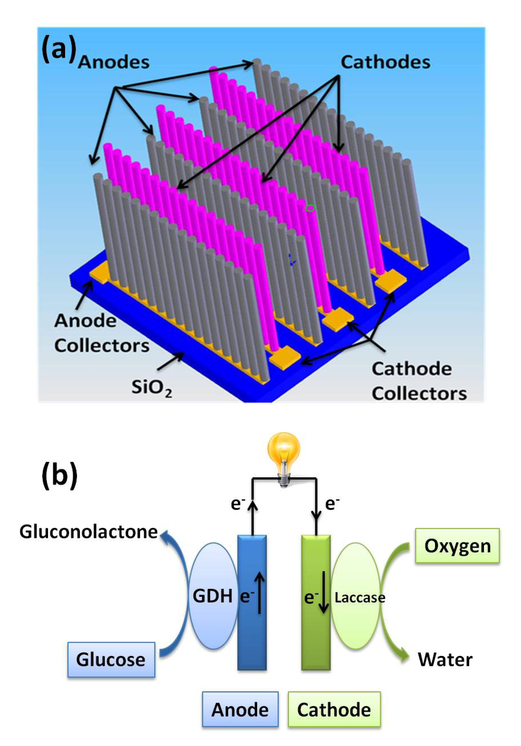
2. Mechanism of EBFCs

Among today’s glucose-oxidizing enzymes, glucose oxidase (GOx) has been the most widely used redox enzyme due to its thermostability and high selectivity for glucose. However, glucose oxidase is defined as an oxidoreductase that can utilize oxygen as the external electron acceptor, which will cause the oxygen competetion between GOx and laccase catalysis. Therefore, glucose dehydrogenase (GDH), which is insensitive to oxygen, has been considered in this study for simplicity. Figure 1b shows the schematic of 3-D microelectrodes immobilized with GDH and laccase on anode and cathode, respectively. The overall redox reactions of this EBFC are given by:
  • Anode:
    Energies 07 04694 i001
  • Cathode:
    Energies 07 04694 i002
In principle, glucose is catalyzed by GDH and produces gluconolactone and hydrogen ions and generates electrons on the anode. On the cathode, the laccase catalyst reduces oxygen and water is generated by combining with electrons and hydrogen ions. Laccase is multi-copper protein that can catalyze the four electron reduction of oxygen to water. It is believed that laccase catalysis involves reduction of the copper by reducing substrate. The FAD-GDH comprises oxidoreductases that catalyze the first hydroxyl group of glucose and other sugar molecules, utilizing FAD as the primary electron acceptor. When GDH catalyzes glucose oxidation, the GDH-FAD is reduced to GOx-FADH2, which can be oxidized by the electrode back to GDH-FAD shown in the following reactions:
GDH-FAD + Glucose → GDH-FADH2 + Gluconolactone
GDH-FADH2 ↔ GDH-FAD + 2H+ + 2e
For this modeling, we will consider that enzyme (GDH-FAD/laccase) and electrode reactions are coupled by DET in this simulation. In such a system, the coupled overall process is the redox transformation of the substrates, which can be considered as an enzyme-catalyzed electrode process.
The efficiency of utilization of the fuel is directly related to the enzyme kinetics. The Michaelis-Menten kinetics for a single-substrate reaction is considered for anode and cathode, respectively:
Energies 07 04694 i003
where S and P are the substrate and product; E is the enzyme; ES is enzyme and substrate complex by initial bimolecular reaction; k1, k−1 are the rate constants for the association and breakdown, respectively of the complex and k2 denote the rate constants for the breakdown of the complex. The steady state kinetics of the enzyme reaction (v) is expressed by:
Energies 07 04694 i004
where kcat (=k2) is catalytic rate constant, KM (=(k2 + k−1)/k1) is the Michaelis-Menten constant of the enzyme. [E] and [S] are the concentration of the enzyme and the substrate.

3. Simulation Modeling

A computational model of an EBFC system to simulate mass transport, enzyme kinetics and electric current were developed by COMSOL Multiphysics, which solves partial differential equations (PDEs) by finite element techniques. The schematic of a prototype design of an EBFC chip, having 3-D microelectrode arrays was proposed as shown in Figure 1a. The footprint was chosen as 15 × 15 mm in square. The diameter for each microelectrode is 30 µm and enzyme layer thickness is 10 µm. The height of the microelectrode has been chosen from 100 to 200 µm based on current C-MEMS technology. In order to simplify the simulation, 2-D modeling has been applied in this study. With the microelectrode dimensions and footprint area, the change of distance between two electrodes (well width) ranges from 10–200 µm, which will affect the number of microelectrodes within the same footprint in one row on the chip. In our previous paper, the pressure variation in each cardiac cycle is considered with a simple trigonometry function to maintain normal systolic/diastolic pressure variation of 120/80 mmHg in the artery [39]. The amount of glucose flowing in the artery will also change at the inlet according to contraction and extraction of blood artery which is considered as a transient model. In this study, in order to obtain the optimized design for 3-D microelectrode arrays, we simulate the model considering the 3-D microelectrode arrays is in the experimental beaker with a glucose concentration at 5 mol·m−3. In the diffusion module, the diffusion of substrate with enzyme kinetics is solved based on reaction-diffusion equations:
Energies 07 04694 i005
where c is the concentration of substrate; D is the diffusion coefficient; v is the redox reaction rate.
To compute the electric field ∇ø, we need to solve the continuity equation for current ∇J = 0. Current density is proportional to the conductivity and electric field J = σ∇ø. Conduction in this simulation occurs by a combination of electric field and diffusion, which is proportional to diffusion constant D and charge density. The current density is then described by generalized Ohm’s law:
Energies 07 04694 i006
where σ is electric conductivity of the buffer and F is the Faraday constant. In the above equation, electroneutrality conditions are assumed.
The overall of redox reaction at the electrode surface is assumed to be reversible. The electrode potential-concentration relationship is defined by the Nernst Equation:
Energies 07 04694 i007
where ø o is the standard potential, [ ø o x ] and [ ø r e d ] represent the concentration of the oxidized and reduced enzyme. In this simulation, we consider the concentration of the oxidized and reduced forms are from the active redox center of FAD/FADH2 for GDH and type 1 copper for laccase.
The boundary conditions and the relevant constants are shown in Table 1 and Table 2, respectively.
Table 1. Boundary conditions for simulation models.
BoundaryDiffusionPotential
Top boundary of bulk domain c = c 0 n · J = 0
Bulk-enzyme interface n ( N 1 N 2 ) = 0 V = V 0
Enzyme-electrode interface n ( N 1 N 2 ) = 0 n ( J 1 J 2 ) = 0
Side and bottom boundaries of bulk domain n ( D c ) = 0   n · J = 0
Table 2. Simulation parameters.
ConstantRef. ValueReference
R8.314 J·mol·K−1-
T300 K-
F96,485 C·mol−1-
Dglucose7 × 10−10 m2·s−1[42,43,44]
Doxygen1.74 × 10−9 m2·s−1[45,46]
KM_GDH17.4 mM[47]
KM_laccase133.4 mM[48]
kcat_GDH360 s−1[47]
kcat_laccase117 s−1[48]
ø oA−0.32 V[49]
ø oC0.585 V[49]
σcarbon8000 S·m−1[50]
σsubstrate4 S·m−1-
In addition, several assumptions have been made in this simulation:
(1)
2-D simulation is used to simplify the 3-D microelectrode design.
(2)
The DET between enzyme and electrode is assumed.
(3)
The enzyme kinetics constant is obtained from the literatures based on immobilized enzymes.
(4)
The enzyme is uniformly distributed in the enzyme layer.
(5)
Negligible change in heat transfer is assumed between enzyme layer and electrode interface.
(6)
Temperature distribution around the EBFCs is assumed to be uniform.

4. Results and Discussions

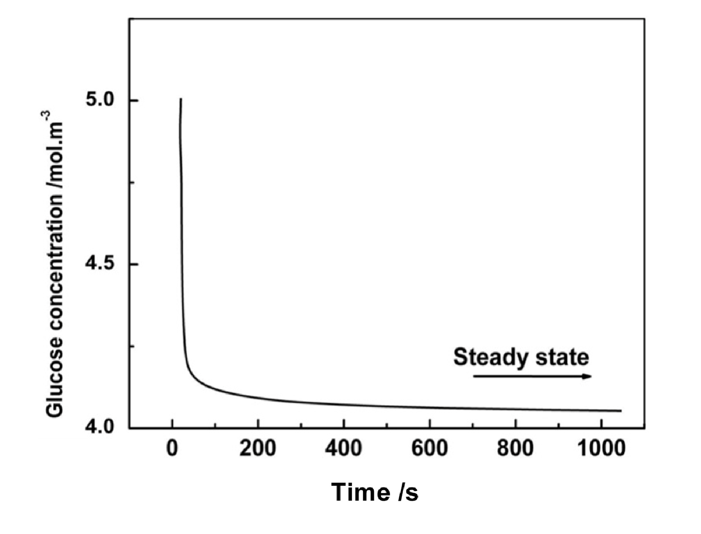
4.1. The Steady State Response

Initially at time t = 0, the concentration of the glucose is constant along the electrode. From t > 0, the glucose starts to react with enzyme. The glucose depletion from the bottom of the electrode causes the glucose diffusion from the bulk domain to the well between electrodes. We then investigated the response time for glucose to diffuse within one pair of microelectrodes before reaching a steady state. Figure 2 illustrates the steady state response time for an electrode with a height of 200 µm and a well width of 40 µm. The glucose concentration is from the top point of the electrode. Based on the glucose concentration evolution over operation time, the steady state response time for microelectrode arrays at this dimension is around 700 s. In the following study, we investigate the EBFC performance after the steady state condition has been met for each configuration of microelectrode array.
Figure 2. Response time to reach steady state for electrode at height of 200 µm with well width of 100 µm.
Energies 07 04694 g002

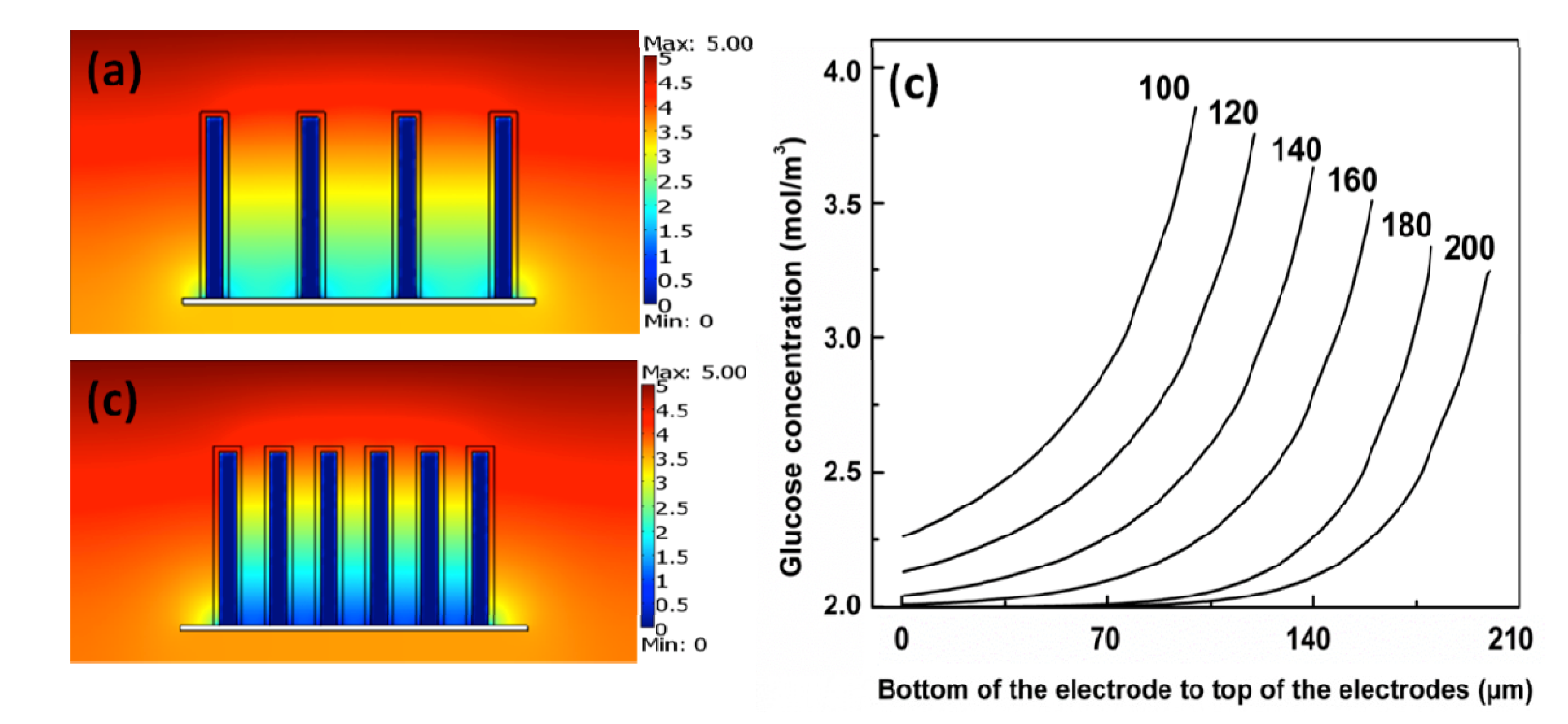
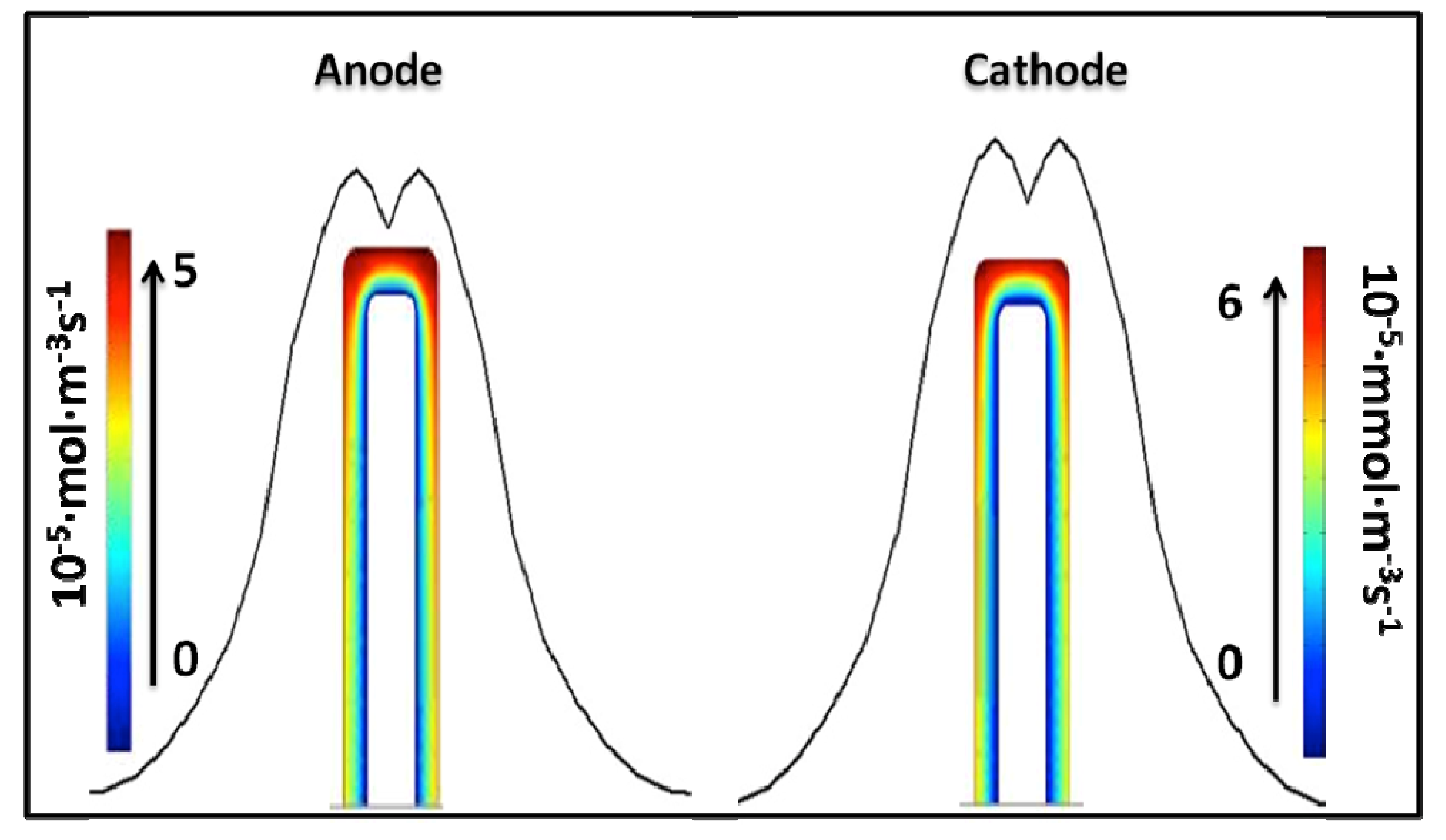
4.2. Impact of Mass Transport and Reaction Rate

Mass transport is investigated based on glucose and oxygen diffusion around electrodes in different microelectrode array configurations. The glucose concentrations along the electrode surface inside the well at different electrode dimensions after reaching steady state are shown in Figure 3a,b. The starting point is 0.05 µm from the bottom to the top of the electrode. Ideally, glucose should interact with the total surface area of electrodes from top to bottom to fully utilize the enzymes immobilized onto them. However, the glucose reacts immediately with the top portion of the electrode where it diffuses first and the rest of glucose reacts gradually down to the bottom of the electrode. From the results, we observed the non-uniformity of the concentration of glucose along the surface of electrode at all dimensions. There is a decrease in the glucose concentration along the vertical direction inside the well from the top to bottom of the electrode. We have simulated a microelectrode array with height of 200 µm with two well widths of 40 and 100 µm. The smaller glucose depletion occurs for the larger well width between two electrodes because there is more space for glucose. In order to investigate the effect of height on diffusion change, different height of microelectrode arrays at a fixed well width of 50 µm have been simulated and results were shown in Figure 3c. The glucose concentration is decreased from the top to the bottom of the electrode for all different height of microelectrode arrays. The concentration of the bottom of the electrode decreases as the height of the electrode increase. The competition between higher enzyme reaction rate and lower diffusion rate causes glucose depletion throughout the electrode surface and consequently generates non-uniform glucose concentration. Since the concentration gradient on the electrode surface is influenced by the enzyme kinetics defined by the Michaelis-Menten reaction rate Equation (6), the concentration gradient of the glucose and oxygen along the vertical direction from top to bottom of electrode surface leads to the relevant enzyme reaction variation in the enzyme layer shown in Figure 4. From the simulation results, the enzyme reaction rate decreases from the top to bottom along the surface of microelectrodes, which is consistent with the concentration gradient results. It is also observed that the outer surfaces of the microelectrodes experience larger enzyme reaction rates in the enzyme layer due to the diffusion. In addition, the noticeable maximum enzyme reaction rate at the top edges of the microelectrodes results from the edge effect of the electrode design.
Even though by increasing the well width, the glucose concentration gradient has less difference along the microelectrode surface from the bottom to the top thus the glucose depletion is getting smaller, the number of microelectrodes within the same footprint area decreases. Because the current and power density are based on the total number of microeletrodes, it is necessary to find the optimum configuration of microelectrode arrays based on the simulation results from current density.
Figure 3. Glucose concentration from the bottom to the top of electrode at electrode height of 200 µm with different well width (ww) (a) 40 µm; (b) 100 µm respectively; (c) gluocse concentration from the bottom to the top of electrode at different height from 100 µm to 200 µm.
Energies 07 04694 g003
Figure 4. Change in reaction rate along the surface of anode and cathode at electrode height of 200 µm.
Energies 07 04694 g004

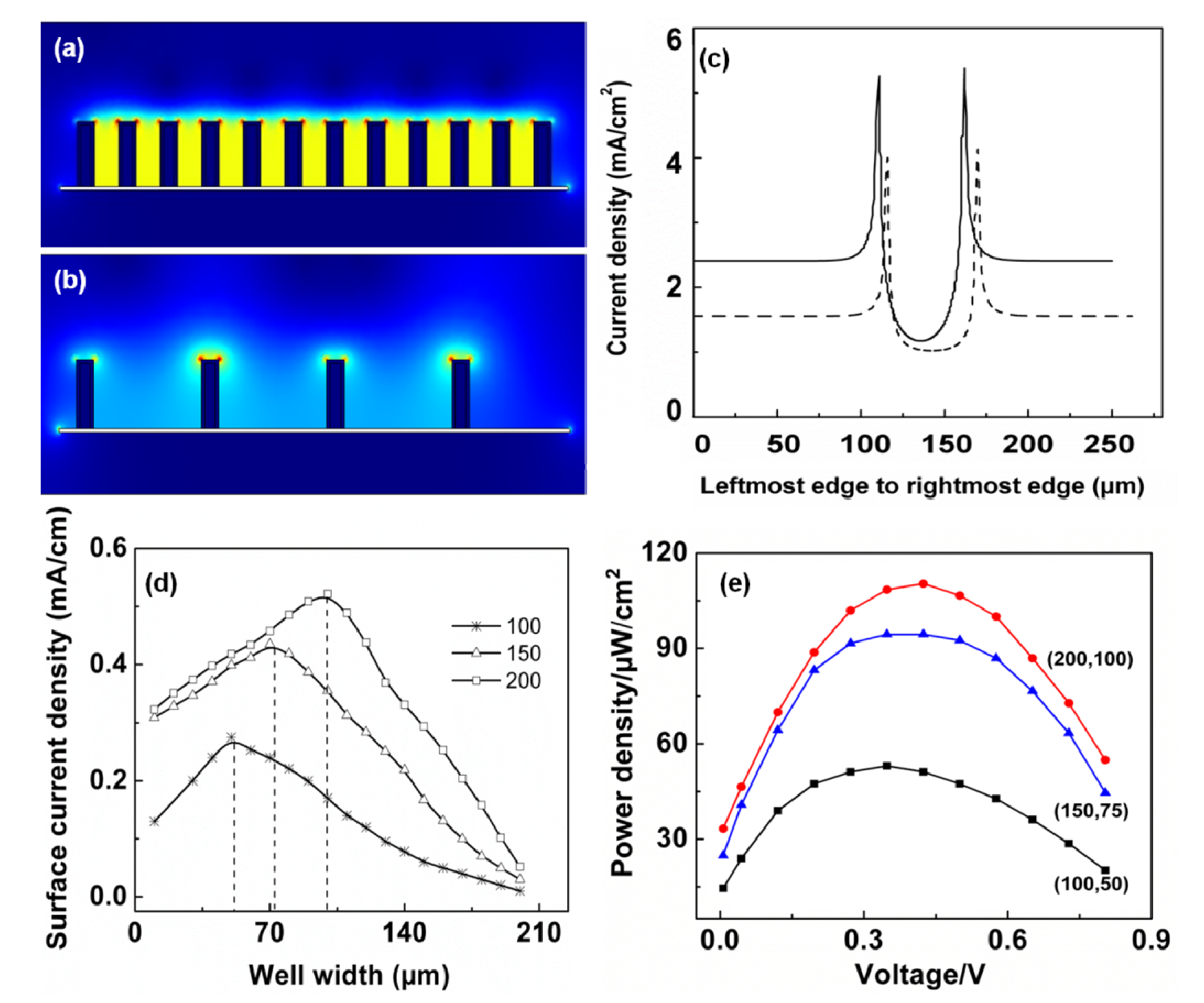
4.3. The Cell Performance of EBFCs

The current density of whole microelectrode arrays were simulated as shown in Figure 5a–c. The Figure 5a,b are the current density profiles for microelectrode arrays at the same height with different well width within the same footprint. From the previous diffusion result, the larger well width has better glucose diffusion along the electrode vertical surface. The substrate will react with the enzymes immobilized on the top of the electrodes first and at the meantime diffuse and react along the electrode surface from top to bottom. The competition between higher enzyme reaction rate and lower diffusion rate causes non-uniform electron transfer throughout the electrode surface and consequently generates a non-uniform current density. The current density is relatively low from the bottom of the electrode and increase in the higher portion of the electrode. It is observed that the current density maximum occurs on the top corner of each electrode. Figure 5c is the corresponding current density plot for these two configurations of microelectrode arrays. The current density for larger well width (solid line) is higher than that of smaller well width (dashed line). As we discussed before, even though current density for larger well width is higher, increase in well width causes a decrease in the number of microelectrodes in the same footprint. Therefore, integration of the current density along the electrode surface in one row on the chip has been evaluated at different well width for each constant height of microelectrode arrays, which qualitatively represents the total current collected on each post-electrode in one row within the same footprint area. The change of the line current density with respect to the well width and height is obtained by simulation and shown in Figure 5d. For each height, with the increase of well width the line current density reaches a peak and then decreases. This is because even though glucose depletion is less in the larger well width, less micoelectrodes in one row could result in a decrease in total line current density. A conclusion can be drawn from the simulation results that the maximum line current density is obtained when the height is roughly equal to two times the well width. It could be noticed that among the three cases, microelectrode array with 200 µm exhibited the highest current density of 0.52 mA/cm2. Ease of fabrication is an important consideration and since it is difficult to manufacture carbon microelectrodes higher than 200 µm by C-MEMS. Therefore, based on the results and practical application, to design the microelectrode arrays within 15 mm × 15 mm foot print, the optimum configuration is height and well width keeping as 200 µm and 100 µm.
One of the most important characteristics to examine in an EBFC is power density. In this work, simulation was conducted by incorporating the Nernst equation. To compare the performance among different electrode configurations, we simulated EBFCs with three heights: 100, 150 and 200 µm, all at 2:1 fixed ratio of height to well width based on the previous results, which the optimized configuration of microelectrodes is that the height is twice of the well width. Various external loads at the range of 5–500 kΩ are considered in the simulation in order to understand the power density-voltage relationship. As shown in Figure 5e, the power density for all four configurations of microelectrodes increases as the voltage gets higher and reaches a maximum. After reaching the maximum, increasing the voltage leads to a decrease in the power density. The electrode array with height of 200 µm is observed to have the highest power density at around 110 µW/cm2 when the voltage is approximately 0.44 V. This performance of EBFC is adequate for operation of low-voltage CMOS integrated circuits.
Figure 5. (a,b) Current density profile for one row of microelectrodes at 100 µm with different well width 50 µm and 100 µm; (c) current density at the surface of electrode along the vertical direction inside the well: 50 µm (dash line); 100 µm (solid line); (d) change of line current density with respect to electrode height and well width; (e) power density vs. cell voltage at different electrode heights. The height to well width ratio of electrode is 2:1.
Energies 07 04694 g005

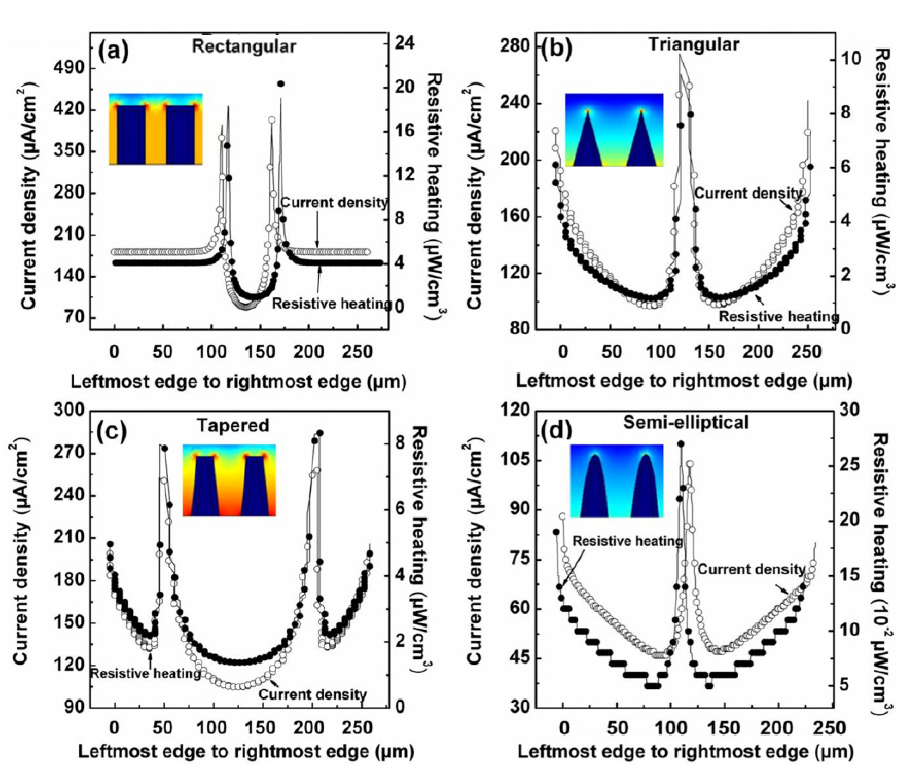
4.4. Geometry of the Electrodes

The simulation profile of electric field is shown in Figure 6 for rectangular electrodes. The contour plot also shows the electric field; with more contours at higher value of electric field and less contours at lesser values of electric field. The arrow plot shows the direction of the charge transfer, with tails coming out of cathodes and heads going into anodes. The electric field is inversely proportional to the distance between electrodes and hence it is higher in between the post rather than in surrounding region. At the corners and sharp edges as area decreases the charge density increases and so does the electric field, because the electric field is perpendicular to the surface area and proportional to the charge density. According to Ohm’s law, current density is directly proportional to electric field, and hence the current density is higher at sharp corners and edges. This may result in more heat dissipation/resistive heating and so electrodes can eventually degrade at those portions of electrodes. This higher heating can cause harm to enzymes immobilized onto posts. This may reduce the life span of enzymes, which can reduce the fuel cell longevity. In order for the electrodes and enzymes to last for long time, current density should be uniform around electrodes and edge effect should be minimized.
Figure 6. Electric field (surface, contour and arrow plot) profile surrounding the rectangle electrodes with constant potential of 0.585 V on cathode and −0.32 V on anode.
Energies 07 04694 g006
From the above discussions, it is inferred that not only dimensions, but the geometry of the electrodes also plays an important role in EBFC output performance. To find out more reliable and long lasting electrode configurations, four different geometries of one pair of electrodes with height of 100 µm, well width of 20 µm at bottom and diameter of 20 µm are implemented in order to obtain a more suitable configuration with uniform current density along the single electrode. In all these simulations, the open circuit potential for anodes is at −0.32 V (vs. SHE) and cathodes at 0.585 V (vs. SHE). For the anode, when the potential is in the interval from −0.32 V to 0 V (vs. SHE), dissolved O2 would get reduced on the carbon and then decrease the current, voltage and faradic efficiency [51]. In order to simplify the simulation, we don’t take into account any putative O2 reduction on the anode. The current density and resistive heating profiles for: (a) rectangular; (b) triangular; (c) tapered; and (d) semi-elliptical electrodes with height of 100 µm, well width of 20 µm at bottom and diameter of 20 µm are shown in Figure 7a–d, respectively. In the figures, the left Y-axis and the right Y-axis show the values for current density and resistive heating, respectively. The current density and resistive heating profiles follow almost the same trend for all the four geometries since heat dissipation is proportional to current density. The values for current density and resistive heating, for all the geometries, are summarized in Table 3.
Table 3. Statistical analysis of current density (CD) and resistive heating (RH) for rectangular, triangular, tapered and semi-elliptical geometry of electrodes.
GeometrySide EdgesTop EdgeCorners
PropertyCD (μA·cm−2)RH (μW·cm−3)CD (μA·cm−2)RH (μW·cm−3)CD (μA·cm−2)RH (μW·cm−3)
Rectangular17041001.541023
Triangular90–2251–8--270(top) 230(bottom)12(top) 7(bottom)
Tapered130–2102.5–5125–1351–32508.5
Semi-elliptical45–900.05–0.17--105(top) 47(bottom)0.27(top) 0.05(bottom)
Figure 7. Current density and resistive heating distribution plots for four different geometries of electrodes: (a) rectangular; (b) triangular; (c) tapered; and (d) semi-elliptical.
Energies 07 04694 g007
From the simulation results, it could be observed that the current density values are very high at the tip corners of the rectangular electrodes. The resistive heating is almost five times higher at tip corners compared to other locations due to the edge effect. In contrast, for the other majority locations of side and top of electrodes, the current density and resistive heating are uniformly distributed. In triangular electrodes, those localized high current density and resistive heating regions, are located at the tips of the electrodes, with much more stronger values than the values taken from the side walls. In the case of tapered electrodes, the non-uniformity of current density and resistive heating are much less compared to the rectangular and triangular electrode geometries. In semi-elliptical electrodes, the current density and resistive heating values are more uniformly distributed compared to all other geometries. The resistive heating values are very small at the top curvature as well as at edges. According to Ohm’s law, current density is directly proportional to electric field, and hence the current density is higher at sharp corners and edges. From these simulation results, semi-elliptical shaped geometry is more favorable due to lack of sharp corners and edges. But it should be noted that although semi-elliptical electrodes provides the least resistive heating, it might not be easy to fabricate such microstructures using conventional C-MEMS technology.
In order to truly check the plausibility of different computational models for EBFCs, effort is needed on experimental work, including fabrication techniques of different shapes of electrodes. At the same time, other essential EBFCs parameters such as overpotential, internal cell resistances as well as the cell performance in transient condition should be also investigated in the future work.

5. Conclusions

In this paper, a detailed simulation on 3-D microelectrode EBFC arrays is investigated. The novelty of this report is the incorporation of enzyme kinetics in the EBFC modeling. Optimization of the EBFC configuration suggests that in order to maximize the cell performance within the fixed print area, the ratio of the height and the well width of the electrode should be kept as 2:1 in general. From the modeling, the maximum power density for 3-D microelectrode EBFC reaches 110 µW/cm2 at 0.44 V in voltage when the dimension of electrodes is keeping height as 200 µm and well width as 100 µm. From current density and resistive heating distribution analysis for different geometries of electrodes, we highly recommend that semi-elliptical shaped electrode is more favorable to deliver uniform current density along the electrode.

Author Contributions

Yin Song performed the simulation and wrote the paper, Varun wrote the introduction and Chunlei Wang reviewed and edited the manuscript. All authors read and approved the manuscript.

Nomenclature

[i]
concentration of component i (mol·m−3)
c
concentration
D
diffusion coefficient (m2·s−1)
F
Faraday’s constant (C·mol−1)
JJ
current density (mA/cm2)
k
rate constant for enzyme complex (s−1)
kcat
catalytic rate constant (s−1)
KM
Michaelis Mention constant (mM)
N
flux (mol·m−2·s−1)
R
universal gas constant (J·mol·K−1)
T
room temperature (K)
v
enzyme reaction (mol·m−3·s−1)
z
number of electron transferred

Greek

σ
electric conductivity (S·m−1)
ø
electric potential (V)

Conflicts of Interest

The authors declare no conflict of interest.

References

  1. Mano, N.; Heller, A. Biofuel cells and their development. J. Electrochem. Soc. 2013, 150, A1136–A1138. [Google Scholar] [CrossRef]
  2. Palmore, G.; Whitesides, G.M. Microbial and enzymatic biofuel cells. In Enzymatic Conversion of Biomass for Fuels Production; Himmel, E., Ed.; American Chemical Society: Washington, DC, USA, 1994; Volume 566, pp. 271–290. [Google Scholar]
  3. Ivnitski, D.; Branch, B.; Atanassov, P.; Apblett, C. Glucose oxidase anode for biofuel cell based on direct electron transfer. Electrochem. Commun. 2006, 8, 1204–1210. [Google Scholar] [CrossRef]
  4. Katz, E.; Shipway, A.N.; Willner, I. Handbook of Fuel Cells—Fundamentals, Technology and Applications; John Wiley & Sons, Ltd.: Hoboken, NJ, USA, 2003; pp. 355–381. [Google Scholar]
  5. Heller, A. Miniature biofuel cells. Chem. Chem. Phys. 2004, 6, 209–216. [Google Scholar] [CrossRef]
  6. Ramanavicius, A.; Kausaite, A.; Ramanaviciene, A. Biofuel cell based on direct bioelectrocatalysis. Biosens. Bioelectron. 2005, 20, 1962–1967. [Google Scholar] [CrossRef] [PubMed]
  7. Halamkova, L.; Halamek, J.; Bocharova, V.; Szczupak, A.; Alfonta, L.; Katz, E. Implantable biofuel cell operating in a living snail. J. Am. Chem. Soc. 2012, 134, 5040–5043. [Google Scholar] [CrossRef] [PubMed]
  8. Coman, V.; Ludwig, R.; Harreither, W.; Haltrich, D.; Gorton, L.; Ruzgas, T.; Shleev, S. A direct electron transfer-based glucose/oxygen biofuel cell operating in human serum. Fuel. Cells 2010, 10, 9–16. [Google Scholar]
  9. Southcott, M.; MacVittie, K.; Halámek, J.; Halámková, L.; Jemison, WD.; Lobel, R.; Katz, E. Pacemaker powered by implantable biofuel cell operating under conditions mimicking human blood circulatory system–battery not included. Phys. Chem. Chem. Phys. 2013, 15, 6278–6283. [Google Scholar] [CrossRef] [PubMed]
  10. Ringeisen, B.R.; Henderson, E.; Wu, P.; Pietron, J.; Ray, R.; Little, B.; Biffinger, J.; Jones-meehan, J. High power density from a miniature microbial fuel cell using shewanella oneidensis DSP10. Environ. Sci. Technol. 2006, 40, 2629–2634. [Google Scholar] [CrossRef] [PubMed]
  11. Long, J.W.; Dunn, B.; Rolison, D.; White, H.S. Three-dimensional battery architectures. Chem. Rev. 2004, 104, 4463–4492. [Google Scholar] [CrossRef] [PubMed]
  12. Dunn, B.; Long, J.W.; Rolison, D. Rethinking multifunction in three dimensions for miniaturizing electrical energy storage. Interface 2008, 17, 49–53. [Google Scholar]
  13. Anandan, V.; Yang, X.; Kim, E.; Rao, Y.; Zhang, G. Role of reaction kinetics and mass transport in glucose sensing with nanopillar array electrodes. J. Biol. Eng. 2007, 1, 1–10. [Google Scholar] [CrossRef] [PubMed]
  14. Godino, N.; Borrise, X.; Munoz, F.X.; Campo, F.J.; Compton, R. Mass transport to nanoelectrode arrays and limitations of diffusion domain approach: Theory and experiment. J. Phys. Chem. 2009, 113, 11119–11125. [Google Scholar]
  15. Wang, C.; Taherabadi, L.; Jia, G.; Madou, M. C-MEMS for the manufacture of 3D microbatteries. Electrochem. Solid State Lett. 2004, 7, A435–A438. [Google Scholar] [CrossRef]
  16. Wang, C.; Jia, G.; Taherabadi, L.; Madou, M.J. A novel method for the fabrication of high aspect ratio C-MEMS structures. Microelectromechanical Syst. 2005, 14, 348–358. [Google Scholar] [CrossRef]
  17. Wang, C.; Madou, M. From MEMS to NEMS with carbon. Biosens. Bioelectron. 2005, 20, 2181–2187. [Google Scholar] [CrossRef] [PubMed]
  18. Park, B.Y.; Taherabadi, L.; Wang, C.; Zoval, J.; Madou, M. Morphological and electrical properties of carbon films of various thinknesses carbonized from photoresist and the implications for C-MEMS devices in conductive media. J. Electrochem. Soc. 2005, 152, J136–J143. [Google Scholar] [CrossRef]
  19. Malladi, K.; Wang, C.; Madou, M. Microfabrication of suspended C-MEMS structures by EB writer and pyrolysis. Carbon 2006, 44, 2602–2607. [Google Scholar] [CrossRef]
  20. Park, B.; Zaouk, Y.R.; Wang, C.; Madou, M. Fractal C-MEMS architectures for 3D miniature power and sensor applications. ECS Trans. 2006, 1, 1–11. [Google Scholar]
  21. Park, B.Y.; Zaouk, R.; Wang, C.; Zoval, J.; Madou, M. Fractal C-MEMS electrodes: Theory and preliminary fabrication. ECS Trans. 2007, 4, 83–92. [Google Scholar]
  22. Wang, C.; Zaouk, R.B.; Park, Y.; Madou, M. Carbon as a MEMS material: Micro and nano fabrication of pyrolyzed photoresist carbon. Int. J. Manuf. Tech. Manag. 2008, 13, 360–375. [Google Scholar]
  23. Min, H.; Park, B.Y.; Taherabadi, L.; Wang, C.; Yeh, Y.; Zaouk, R.; Madou, M.; Dunn, B. Fabrication and properties of a carbon/polypyrrole three-dimensional microbattery. J. Power Sour. 2008, 178, 795–800. [Google Scholar] [CrossRef]
  24. Yang, J.H.; Penmatsa, V.; Tajima, S.; Kawarada, H.; Wang, C. Direct amination on 3D pyrolyzed carbon micropattern surface for DNA detection. Mater. Lett. 2009, 63, 2680–2683. [Google Scholar] [CrossRef]
  25. Chen, W.; Beidaghi, M.; Penmatsa, V.; Li, W.; Wang, C. Integration of carbon nanotubes to C-MEMS for on-chip supercapacitors. IEEE Nanotech 2010, 9, 1222–1225. [Google Scholar]
  26. Penmatsa, V.; Yang, J.H.; Yu, Y.; Wang, C. Fabrication of porous carbon micropillars using a block copolymer as porogen. Carbon 2010, 48, 4109–4115. [Google Scholar] [CrossRef]
  27. Penmatsa, V.; Kawarada, H.; Wang, C. Fabrication of carbon nanostructures using photo nanoimprint lithography and pyrolysis. J. Micromech. Microeng. 2012, 22, 045024. [Google Scholar] [CrossRef]
  28. Penmatsa, V.; Kim, T.; Beidaghi, M.; Kawarada, H.; Wang, Z.; Gu, L.; Wang, C. Three-dimensional graphene nanosheets encrusted carbon micropillar arrays for electrochemical sensing. Nanoscale 2012, 4, 3673–3678. [Google Scholar] [CrossRef] [PubMed]
  29. Penmatsa, V.; Ruslinda, R.; Beidaghi, M.; Kawarada, H.; Wang, C. Platelet-derived growth factor oncoprotein detection using three-dimensional carbon microarrays. Biosens. Bioelectron. 2013, 39, 118–123. [Google Scholar] [CrossRef] [PubMed]
  30. Penmatsa, V.; Ruslinda, R.; Beidaghi, M.; Kawarada, H.; Wang, C. Functionalized three-dimensional carbon microarrays for cancer biomarker detection. ECS Trans. 2013, 45, 7–14. [Google Scholar] [CrossRef]
  31. Penmatsa, V. Functionalized carbon micro/nanostructures for biomolecular detection. Florida International University, ProQuest, UMI Dissertations Publishing, 2012; 3554197. [Google Scholar]
  32. Miyake, T.; Yoshino, S.; Yamada, T.; Hata, K.; Nishizawa, M. Self-regulating enzyme-nanotube ensemble films and their application as flexible electrodes for biofuel cells. J. Am. Chem. Soc. 2011, 133, 5129–5134. [Google Scholar] [CrossRef] [PubMed]
  33. Filip, J.; Sefcovicova, J.; Gemeiner, P.; Tkac, J. Electrochemistry of bilirubin oxidase and its use in preparation of a low cost enzymatic biofuel cell based on a renewable composite binder chitosan. Electrochim. Acta 2013, 87, 366–374. [Google Scholar] [CrossRef]
  34. Krishnan, S.; Armstrong, F.A. Order-of-magnitude enhancement of an enzymatic hydrogen-air fuel cell based on pyrenyl carbon nanostructures. Chem. Sci. 2012, 3, 1015–1023. [Google Scholar] [CrossRef]
  35. Miyake, T.; Haneda, K.; Yoshino, S.; Nishizawa, M. Flexible, layered biofuel cell. Biosens. Bioelectron. 2013, 40, 45–49. [Google Scholar] [CrossRef] [PubMed]
  36. Tasca, F.; Harreither, W.; Ludwig, R.; Gooding, J.J.; Gorton, L. Cellobiose dehydrogenase aryl diazoniunn modified single walled carbon nanotubes: Enhanced direct electron transfer through a positively charged surface. Anal. Chem. 2011, 83, 3042–3049. [Google Scholar] [CrossRef] [PubMed]
  37. Yan, Y.M.; Su, L.; Mao, L.Q. Multi-walled carbon nanotube-based glucose/O2 biofuel cell with glucose oxidase and laccase as biocatalysts. J. Nanosci. Nanotechnol. 2007, 7, 1625–1630. [Google Scholar] [CrossRef] [PubMed]
  38. Lesniewski, A.; Paszewski, M.; Opallo, M. Gold-carbon three dimensional film electrode prepared from oppositely charged conductive nanoparticles by layer-by-layer approach. Electrochem. Commun. 2010, 12, 435–437. [Google Scholar] [CrossRef]
  39. Liang, B.; Fang, L.; Yang, G; Hu, Y.C.; Guo, X.; Ye, X. Direct electron transfer glucose biosensor based on glucose oxidase self-assembled on electrochemically reduced carboxyl graphene. Biosens. Bioelectron 2013, 43, 131–136. [Google Scholar]
  40. Guo, C.X.; Hu, F.P.; Lou, X.W.; Li, C.M. High-performance biofuel cell made with hydrophilic ordered mesoporous carbon as electrode material. J. Power Sour. 2010, 195, 4090–4097. [Google Scholar] [CrossRef]
  41. Parikh, Y.; Yang, J.H.; Wang, C. Optimizing the mass transport phenomenon around micro-electrodes of an enzymatic biofuel cell inside a blood artery via finite element analysis method. J. Power Sour. 2009, 195, 4685–4694. [Google Scholar] [CrossRef]
  42. Picioreanu, C.; Head, I.M.; Katuri, K.P.; Loosdrecht, M.C.M.V.; Scott, K. A computational model for biofilm-based microbial fuel cells. Water Res. 2007, 41, 2921–2940. [Google Scholar] [CrossRef] [PubMed]
  43. Bernhardt, P.V. Enzyme electrochemistry-biocatalysis on an electrode. Aust. J. Chem. 2006, 59, 233–256. [Google Scholar] [CrossRef]
  44. Hamann, C.H.; Hamnett, A.; Vielstich, W. Electrochemistry, 2nd ed.; Wiley-VCH: New York, NY, USA, 1998. [Google Scholar]
  45. Li, H.; Luo, R.; Birgersson, E.; Lam, K.Y. A chemo-electro-mechanical model for simulation of responsive deformation of glucose-sensitive hydrogels with the effect of enzyme catalysis. J. Mech. Phys. Solids 2009, 57, 369–382. [Google Scholar] [CrossRef]
  46. Kouassi, G.; Irudayaraj, J.; McCarty, G. Activity of glucose oxidase functionalized onto magnetic nanoparticles. Biomagn. Res. Technol. 2005, 3, 1–10. [Google Scholar] [CrossRef] [PubMed] [Green Version]
  47. Zafar, M.; Beden, N.; Leech, D.; Sygmund, C.; Ludwig, R.; Gorton, L. Characterization of different FAD-dependent glucosedehydrogenases for possible use in glucose-based biosensors and biofuel cells. Anal. Bioanal. Chem. 2012, 402, 2069–2077. [Google Scholar] [CrossRef] [PubMed]
  48. Rekuća, A.; Bryjaka, J.; Szymańskab, K.; Jarzębski, A. Laccase immobilization on mesostructured cellular foams affords preparations with ultra high activity. Proc. Biochem. 2009, 44, 191–198. [Google Scholar] [CrossRef]
  49. Ahn, M.Y.; Zimmerman, A.R.; Martínez, C.E.; Archibald, D.D.; Bollag, J.M.; Dec, J. Characteristics of Trametes villosa laccase adsorbed on aluminum hydroxide. Enzym. Microb. Technol. 2007, 41, 141–148. [Google Scholar] [CrossRef]
  50. Spaeth, E.E.; Friedlander, S.K. The Diffusion of Oxygen, Carbon dioxide and inert gas in flowing blood. Biophys. J. 1967, 7, 827–851. [Google Scholar] [CrossRef] [PubMed]
  51. Prévoteau, A.; Mano, N. Oxygen reduction on redox mediators may affect glucose biosensors based on “wired enzymes”. Electrochim. Acta 2012, 68, 128–133. [Google Scholar] [CrossRef]

