Article

Comparison and Impact of Waste Heat Recovery Technologies on Passenger Car Fuel Consumption in a Normalized Driving Cycle

1
PSA Peugeot Citroën, 18 rue des Fauvelles, 92256 La Garenne-Colombes Cedex, France
2
Energy Systems, University of Liège, 7, chemins des chevreuils, Bât. B49 (P33), 4000 Liège, Belgium
3
Institut Pprime, University of Poitiers, boulevard Marie et Pierre Curie, Téléport 2, BP 30179, 86962 Futuroscope Chasseneuil Cedex, France
*
Author to whom correspondence should be addressed.
Energies 2014, 7(8), 5273-5290; https://doi.org/10.3390/en7085273
Submission received: 19 June 2014 / Revised: 19 July 2014 / Accepted: 8 August 2014 / Published: 14 August 2014
(This article belongs to the Special Issue Waste Heat Recovery—Strategy and Practice)

Abstract

:
The purpose of this article was to compare different waste heat recovery system technologies designed for automotive applications. A complete literature review is done and results in two comparative graphs. In the second part, simulation models are built and calibrated in order to assess the fuel consumption reduction that can be achieved on a real driving cycle. The strength of this article is that the models are calibrated using actual data. Finally, those simulations results are analyzed and the Rankine cycle and turbocompound are the two most profitable solutions. However the simulations of the turbocompound shows its limitations because the impact on the exhaust pressure drop is not taken into account in the assessment of the car fuel consumption. Fuel reduction of up to 6% could be achieved, depending on the driving cycle and the waste heat recovery technology.

Graphical Abstract

1. Introduction

Currently legislation on carbon dioxide emissions is being set by more and more governments across the World. As illustrated by Figure 1, Europe is a leader in this respect and has targeted an average carbon dioxide emission by the fleet of each car manufacturer of 95 g of CO2 per km in 2020, whereas United States is aiming at a similar goal, but not before 2025. The Chinese government is trying to reach by 2020 a limit of 120 g of carbon dioxide per kilometer and Japan is looking for a goal in 2020 around 100 g of CO2 per kilometer, but globally, the trend is, and will be, to restrict the carbon dioxide emissions.
Figure 1. Carbon dioxide emissions regulations of different governments across the World [1,2,3]. Adapted from [1,2,3].
Energies 07 05273 g001
In order to reach those future regulation targets, improvements in vehicle fuel consumption have to be achieved. Several aspects could be enhanced, but one of the major losses in a gasoline vehicle happens during the combustion process. In recent spark ignition engines, the efficiency can be up to 35% and it is common knowledge that roughly one third of the energy released by the combustion is wasted in the coolant fluid and one third in the exhaust gases. Those percentages vary with the load engine as some authors [4,5] present it.
Those two waste heat sources can be exploited in order to increase the overall efficiency of the engine. The energy released in the coolant is however not a very good candidate for waste heat recovery. This is mostly due to the fact that this energy is at a very low temperature. Thus it is very difficult to harvestt. On the contrary, exhaust gases show a very large potential for waste heat recovery since they exit the engine at a very high temperature [6].
The exhaust line waste heat energy can be recovered by different means. The use of heat engines describing thermodynamic cycles such as Rankine and Stirling engines is possible. A turbine similar to the one of car turbocharger can also be used (turbocompounding) and coupled to an electric machine or to the transmission line of the vehicle. Thermoelectricity is another alternative in which heat is directly converted into electricity. Other more exotic technologies are also currently being researched. For example, thermoacoustic [7], steam turbocharging [8], 5-stroke [9] or 6-stroke [5] engines are among those technologies.
The present paper deals with the comparison of three waste heat recovery systems. The first part of this paper presents a complete state of the art of the waste heat recovery technologies with a major focus on mobile applications (mostly car and truck). At the end of that section, trends are shown and two figures are drawn in order to highlight the advantages and drawbacks of each technology. In the second part, the models of each technology will be introduced. Unlike most articles found in the open literature this paper shows simulation models that have been calibrated in order to allow a meaningful comparison. Finally, simulation results are shown and technologies are compared. The limits of the simulations are presented and discussed.

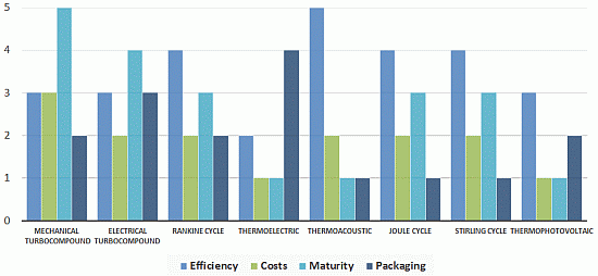
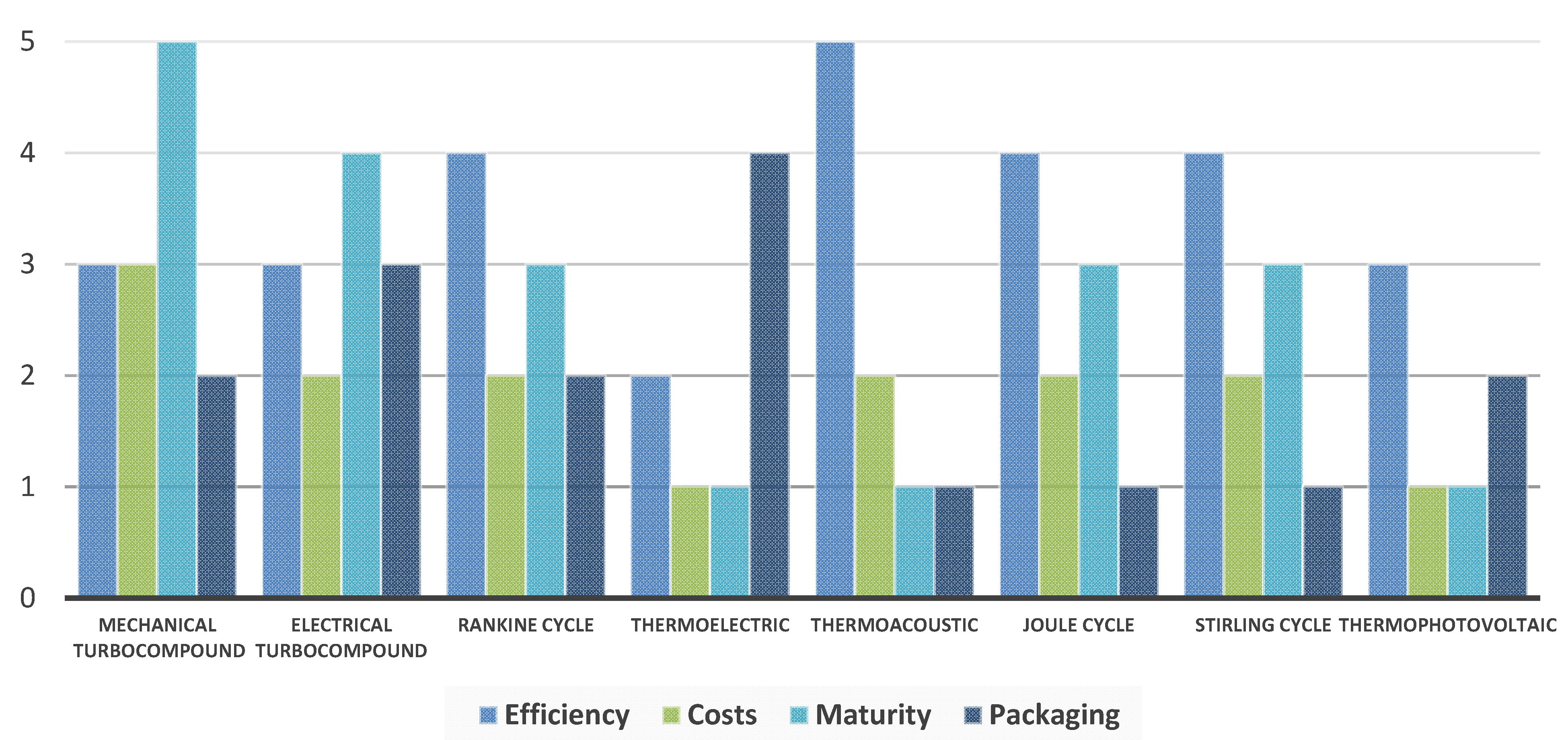
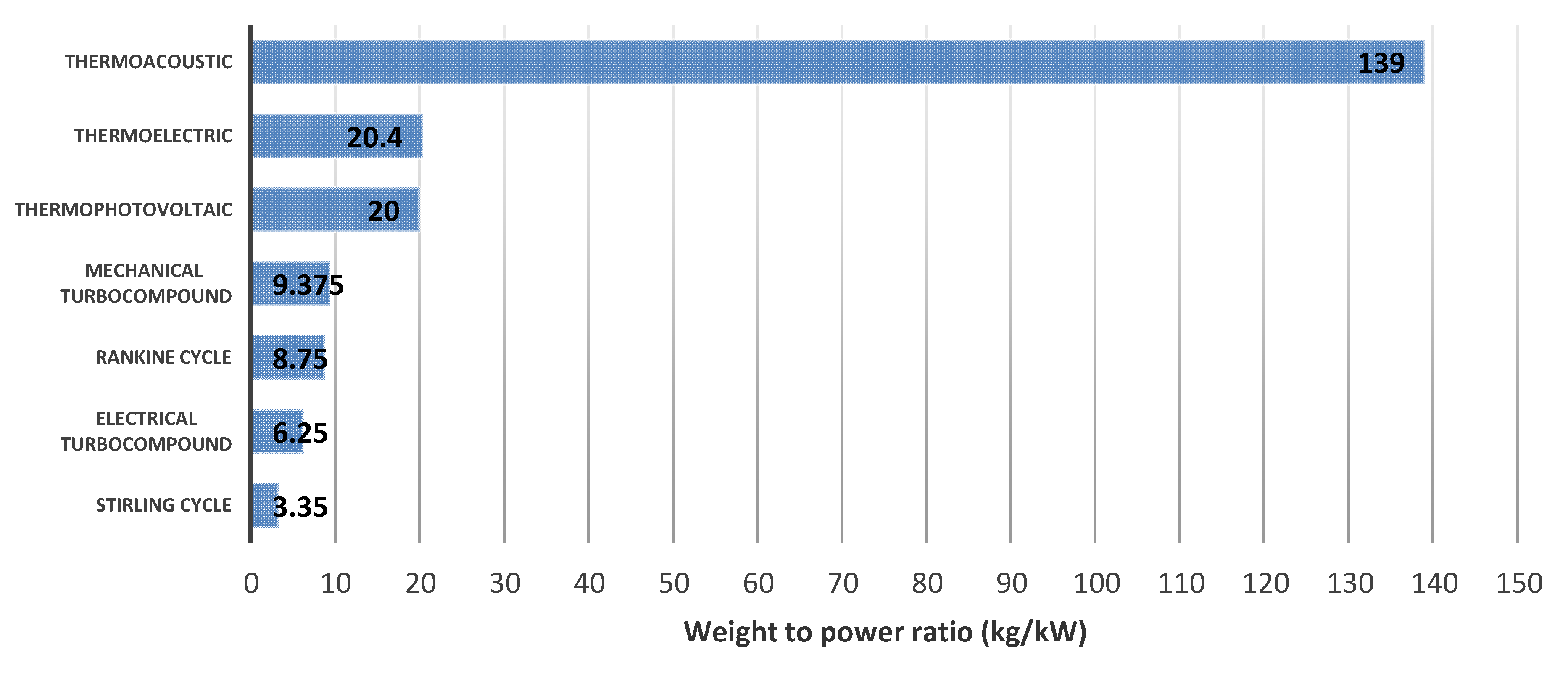
2. Waste Heat Recovery Technologies: Complete State of the Art

The first adaptation of a combustion engine to harvest the energy released in the exhaust gas was achieved as early as in the 1920s. In order to take advantage of the low price of diesel compared to coal, a locomotive used a diesel engine whose exhaust line has been modified to recover the heat and vaporize water to produce additional power [10] by means of a Rankine cycle engine. The exhaust heat recovery system could produce up to 15% to 30% of additional power [11] and was particularly helpful for the diesel engine when the locomotive was starting and required a huge torque. The development was then suspended due to the diminishing difference between fuel prices. Thus, the commercialization of such a locomotive was no longer of interest anymore.
After that period, nothing new really happened until the early 1970s where the oil crisis struck and the US Clean Air Act regulation was implemented. Those motivations drove car manufacturers to reduce car fuel consumption and many researchers investigated the Rankine cycle technology for this purpose. The waste heat recovery with a Rankine cycle was first researched for truck applications. Patel et al. [12] studied an organic Rankine cycle using a mixture of trifluoroethanol and water (50 molar percent each) and a three-stage axial turbine mechanically coupled to the engine shaft. At peak conditions, the system was able to produce an additional 26 kW of mechanical power. No literature on passenger cars has been found during this period.
The first research found on passenger cars was conducted by Oomori et al. [13], who combined the cooling system of an engine and a scroll expander to create a Rankine cycle. They used R123 as the working fluid and were able to reduce the fuel consumption of the car by 3%. However their system’s performance was largely dependent on the ambient temperature.
Research became intensive after 2000 and Endo et al. [6] presented results on a Rankine cycle coupled to a passenger car engine. The expander was an axial swash plate expander operated at a pressure between 40 and 90 bar. Their system showed a maximal cycle efficiency of 13% with produced power up to 3 kW. The following year, the turbosteamer was introduced by Freymann et al. [14]. This waste heat recovery system is composed of two Rankine cycles used to recover waste heat from the coolant and from the exhaust gases. In the following years, that system evolved and used only one Rankine cycle [15]. This last version of the turbosteamer produced electricity with a small impulsion turbine of maximum 2 kW and a target of 10% of improvement in the fuel consumption seemed conceivable. The latest investigations were made by Leduc et al. [16] on the integration of a steam Rankine cycle into a passenger car. The expander is a swash plate type and water is the working fluid of which pressure varied from 10 to 30 bar.
At the beginning of the 20th century, various engineers were developing six-stroke engines in order to avoid paying licensing costs on Otto’s patent. One of those six-stroke engines was developed by Leonard Dyer [17]. The four first strokes of his engine were identical to an Otto engine and the remaining two strokes were dedicated to the vaporization of a small amount of water with the help of some remaining exhaust gas and to its expansion during the last stroke. Very little literature exists about those types of engine and no actual efficiency value of the engine has ever been given. However, Conklin et al. [5] modeled the engine and saw that water injection increased the mean pressure of the engine and thus its power. They produced electrical power up to 810 W using a car alternator with a poor efficiency.
In the late 80s, Birkholz et al. [18] developed a thermoelectric generator and were able to produce up to 58 W in peak conditions, using FeSi2 elements. Since then a lot of research has been conducted on thermoelectric generators for passenger car applications. During the 90s, several studies revealed systems producing power going up to 200 W for passenger cars [19,20,21] or up to 1 kW for a small truck application [22]. However, thermoelectricity always showed very poor efficiency because of the low figure of merit (ZT). The latter number characterizes the thermoelement and actually, most of thermoelectric materials do not show a ZT value above unity. The efficiency is moreover affected by the dependence of the ZT value on the temperature and the requirements to have a matching impedance to the thermoelectric generator. Most commercial generators currently available are made with Bi2Te3 elements. Extensive research is currently focused on finding materials with improved ZT values and lower cost.
In the early 90s, truck manufacturers started to introduce turbocompounding to their vehicles. However, this technology was already known and had prior developments in the aerospace industry, as turbocompound units were first introduced in diesel engines used for planes. The technology was developed in the 1940s [23]. The technology did not meet with success because of the introduction of jet propulsion. Then in the 1990s, truck manufacturers successfully mounted them on trucks [24]. The benefit of a mechanical turbocompound is a fuel consumption reduction of about 5% to 10% [25,26]. Airplanes and trucks both have engines that mostly operate in steady-state conditions. Since it is not the case in passenger cars, the development of turbocompound systems took longer. The project led by CPT [27] aimed at developing a small turbocompound for cars. The turbine produced electricity that was injected back into the vehicle and could produce up to 1 kW [28]. The turbine developed by CPT worked with a pressure ratio between 1 and 1.3 in order to avoid a high backpressure, which would have had a negative impact on the engine fuel consumption. Another project [29] investigated the use of an electric turbocompound. Not much information is given about any experimental results, however the targeted fuel reduction is about 10%.
Thermoacoustics is another technology that is still in a fundamental research phase, since research just started in the 80s. No actual application to a truck or a passenger car is reported in the literature. Thermoacoustics benefits from its reliability and has been used in some space probes for that particular reason [30]. Until the end of the 90s, thermoacoustic generators did not produce a lot of power. However, researchers have recently been able to produce 890 W with 22% efficiency [31] or up to 451 W with 15.3% efficiency [32]. System packaging is currently one of the main disadvantages of those devices.
Systems based on other thermodynamic cycles such as Stirling or Joule cycles are also among possible waste heat recovery technologies. The Stirling cycle engine does seem favorable for automotive or truck integration since it has been evaluated to be very heavy and not compact [33], therefore, no literature on automotive or truck integration has been found. The Joule cycle engine presents also huge drawbacks for mobile applications of waste heat recovery. The Joule cycle engine has a gas-gas heat exchanger that requires a huge heat transfer area in order to achieve a high efficiency. This conclusion was reached by the only researchers that worked on a Joule cycle system for a mobile application in the open literature [34].
Other more exotic technologies have been investigated. As an example, a prototype vehicle moved with a thermophotovoltaic generatorhas been built [35]. This technology is based on the conversion of heat into photons that will produce electricity afterwards. However, this requires a very high temperature since the photon production is proportional to the temperature to the power 4.
To summarize this state of the art review, it can be concluded that waste heat recovery technologies could be helpful in reducing CO2 emissions and three of them are emerging: Rankine cycle systems, turbocompounding and thermoelectric generators. This conclusion is also shared by different authors [36,37,38]. Finally, a few key elements for automotive integration for each technology are summarized by Figure 2. Each technology has been assigned a score in various categories going from 1 to 5, 5 being the best.
Figure 2 shows that turbocompounding and Rankine cycle systems are the most probable technologies to be soon integrated into passenger cars. Thermoelectric generators lack produced power and maturity whereas thermoacoustic or thermophotovoltaic generators are in an early phase of research. Joule and Stirling cycle engines are definitely not suitable for mobile applications due to their volume and/or their weight.
Figure 2. Performance indicators of each waste heat recovery technology for an automotive application.
Energies 07 05273 g002
Another important indicator for a passenger car application is the weight-to-power ratio. According to diverse information provided in the literature, Figure 3 has been drawn and introduces weight-to-power ratio for the aforementioned waste heat recovery technologies. No data have been found however for the Joule cycle engine. For all other technologies, data comes from mobile applications and in priority from passenger car applications. For thermoacoustic generators, figures could not be found for car applications and data from a space probe has been used. Moreover mechanical turbocompound systems for cars does not exist and an additional weight of 5 kg to the electric turbocompound has been added to take into account the weight of the reduction gearbox. Figure 3 clearly shows the advantage of turbocompound units followed by Rankine cycle ones. However, the choice of the technology cannot be based on that only factor.
Figure 3. Weight to power ratio for different waste heat recovery technologies on a mobile application [15,27,30,33,39,40]. Adapted from [15,27,30,33,39,40].
Energies 07 05273 g003
As a conclusion to this state of the art, it should be noticed that the indicators presented in Figure 2 and in Figure 3 are not the only parameters to take into account in the choice of a waste heat recovery technology. According to the literature, thermoelectric generators are not mature yet and some efficient materials have still to be manufactured. In addition to be efficient, the P and N materials of the thermoelectric generator module have to behave similarly in respect to the thermal expansion. Otherwise displacement due to thermal expansion will decrease the lifespan of the thermoelectric device. Bi2Te3 materials are not suited for the temperature range of a gasoline engine and new materials have to be manufactured. The use of skutterudite type materials seems to be the current trend, but research on new materials is very active.
Turbocompounding presents also some drawbacks. Firstly, it increases the exhaust backpressure of the engine, which will affect the exhaust gas after treatment system and the engine performance. An efficient high speed alternator has also to be designed and manufactured at a moderate cost. Radial turbines are the most used among truck turbocompound engines and the only passenger car turbocompound engine also uses a radial type.
The integration volume of the Rankine cycle system is one of its drawbacks but the major one is surely the additional heat that has to be evacuated at the condenser. This will impact either the radiator of the engine or the integration space at the front of the vehicle. A trend for volumetric expanders can be seen in passenger car applications and the use of water seems generalized.

3. Modeling of Various Waste Heat Recovery Technologies
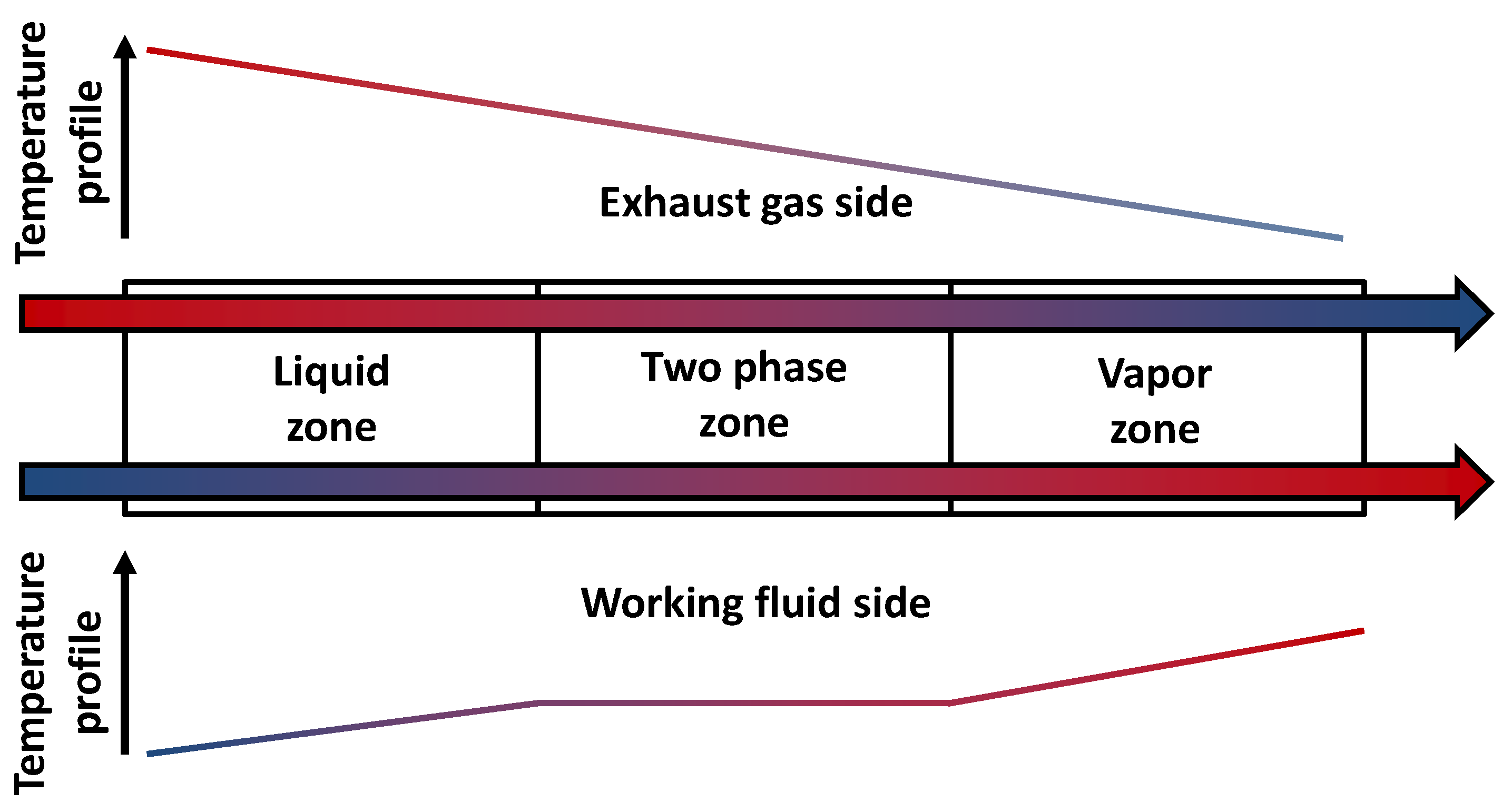
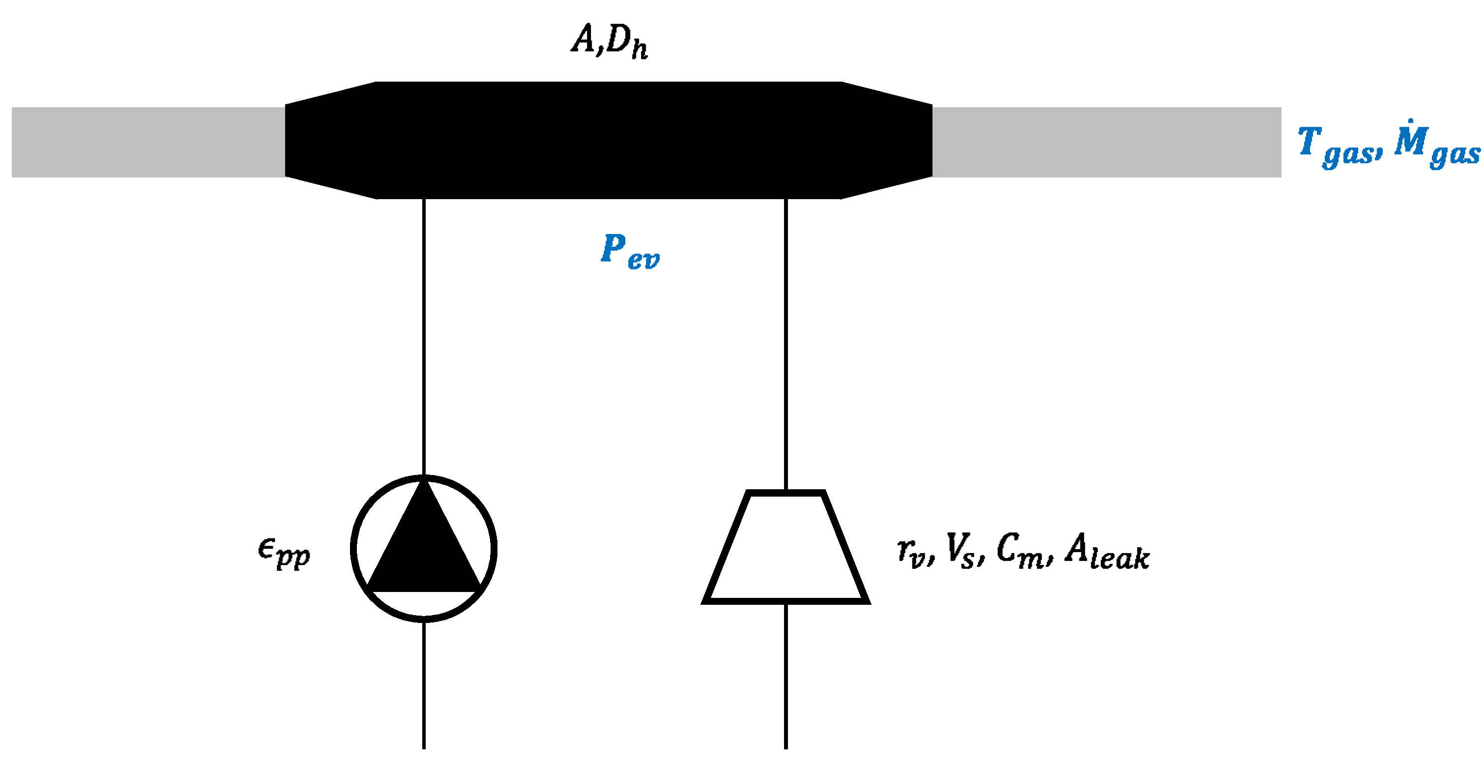
3.1. Rankine Cycle

The Rankine cycle model is a quasi-steady state model developed in Matlab. The model consists of three components including the pump, the evaporator and the expander. The condenser is not modeled in order to decrease the computational time. This hypothesis is valid since the condensation temperature will remain constant by adjusting the mass flow rate of the cooling fluid. The temperature at the entry of the pump is then set by the user. It corresponds to the saturation temperature at the condenser exhaust (which is the condensing temperature if no pressure losses are described) decreased by the subcooling. The pump is simply modeled by its efficiency and Equation (1) is used to determine the outlet temperature:
ϵ p p = h e x , i s h s u h e x h s u
The evaporator is modeled as a counter flow evaporator, illustrated in Figure 4. The model is composed of three moving boundaries zones. The model does not account for pressure losses on the working fluid side. The heat transfer rate is evaluated by an epsilon-NTU method using Equation (2):
Q ˙ = ϵ C ˙ m i n ( T g a s , s u T w f , s u )
Figure 4. Scheme of a three-zone model for an evaporator.
Energies 07 05273 g004
The NTU number can also be evaluated using the efficiency of Equation (2). According to the number of phases in the zone, Equations (3) or (4) are respectively used:
N T U 1 P = 1 ω 1 ln ( ϵ 1 ϵ ω 1 )
N T U 2 P = ln ( 1 1 ϵ )
NTU numbers and AU values are connected with the ratio of capacity flow rates. The heat transfer area can be computed knowing the U value, which can be evaluated with the heat transfer coefficients. These coefficients are given by the Dittus-Boelter correlation (5) for a one-phase zone and by Equation (6) for a two-phase zone [41]:
H T C = C k D h R e 0.8 P r 1 / 3
H T C = C   B o 0.5 k D h R e 0.8 P r 1 / 3
The expander is a volumetric expander. A scroll expander has been chosen and modeled. The choice of the scroll expander has been made regarding the numerous advantages of the scroll expander (low frictional losses, ability to support liquid droplets, size and weight, few moving elements, etc.). The model includes various losses that account for the pressure drop at the supply of the machine, internal leakages and the losses associated with the mismatching between internal and external pressure ratios. The model requires a few geometric parameters such as the built in volume ratio and the displacement (see [42] for a more detailed description of the model).
Figure 5 shows a schematic representation of the Rankine cycle model and indicates the parameters as well as the input variables. The inputs of the model are the temperature and the mass flow rate of the exhaust gases. The control parameters of the cycle are the mass flow rate and the evaporating pressure of the working fluid.
Figure 5. Overview of the Rankine cycle model, the set parameters and the inputs of the model.
Energies 07 05273 g005
The model of the evaporator of the Rankine cycle has been calibrated based on measurements collected on a Rankine cycle test bench [43]. The expander model has not been calibrated due to a lack of data. However, realistic parameters have been set based on previous works.
In order to optimize the performance of the Rankine cycle coupled to the passenger car internal combustion engine, an algorithm has been implemented for the control of the system. The goal of the optimization is to maximize the produced work by adjusting the evaporating pressure. A lower limit is also imposed on the extracted power from exhaust gas in order to ensure that the minimal mass flow rate of working fluid can be vaporized and overheated. Indeed the pump can only provide a fixed range of mass flow rates and too small mass flow rates are unreachable.

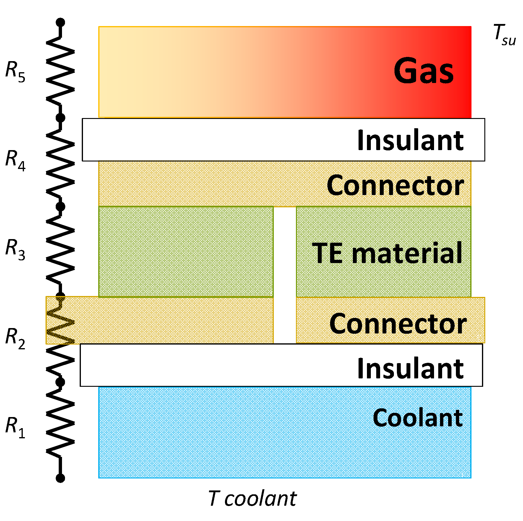
3.2. Thermoelectricity

The thermoelectric generator is modeled considering the thermal resistance scheme presented in Figure 6. The thermal resistances are the convective resistances on the gas and coolant sides, and the conduction resistances of the leg, of the thermoelectric generator and of the insulation.
Figure 6. Scheme for the evaluation of the performance of one thermoelectric generator module.
Energies 07 05273 g006
Geometric parameters and gas properties combined with the definition of the Nusselt number provides the convective heat transfer coefficient between the gas and the hot side of the thermoelectric module.
The heat transfer rate between the gas and the coolant is provided by the following equation, where T s u is the supply temperature of the gas and R t h is the overall thermal resistance. In order to simplify the calculation, the temperature of the coolant is set constant at 100 °C:
Q ˙ = T s u T c o o l a n t R t h
The temperature at the exhaust of the module is provided by Equation (8):
T e x = T s u Q ˙ c p , g a s M ˙
Knowing the temperature on each side of the leg of the module is necessary in order to evaluate the performance of the module. These temperatures are respectively given by Equations (9) and (10):
T c o l d = T c o o l a n t + Q ˙ ( R 1 + R 2 )
T h o t = T c o l d + Q ˙ R 3
In order to calibrate the model, a polynomial law for the evaluation of the mean ZT value in function of the mean leg temperature, defined by means of Equations (9) and (10), is used. Then, the efficiency of the thermoelectric module can be computed by Equation (11):
η = 1 + Z T ¯ 1 1 + Z T ¯ + T c o l d T h o t T h o t T c o l d T h o t
Finally, produced electrical power can be determined by Equation (12) using the efficiency and the heat transfer rate:
W ˙ = η Q ˙

3.3. Turbocompound

Modeling a turbocompound can be quite complex and may need CFD calculations. In order to simplify the approach, data from a turbine of a car turbocharger are used and relationships have been calibrated with those data.
The work produced by the turbine is given by Equation (13):
W ˙ = η M ˙ c p T ( 1 r p 1 γ γ )
In order to determine the pressure ratio, a first relationship relates the gas mass flow rate, the pressure ratio and the turbine speed and is given by the Equation (14). This relationship is a variant of the one given in [44] where the influence of the speed of the turbine has been taken into account:
M ˙ = ( k 1 ( r p 1 ) + k 2 ( r p 1 ) k 3 ) ( r p k 4 ) N k 5
Then, the efficiency has also to be determined. The shape of the efficiency curve versus pressure ratio is similar to the curve used in tire dynamics modeling [45]. The Pacejka formula requires five parameters themselves function of the pressure ratio and the rotational speed. This make a total of 24 parameters to identify, based on experiments, as Equation (15) shows:
η = A + D sin ( C atan ( B ( r p F ) E ( B ( r p F ) atan ( B ( r p F ) ) ) ) )
The parameters   A , B , C , D and E are given by the following five relationships:
A = x 1 e x 2 N + x 3 N x 4 + x 5
B = x 6 e x 7 N
C = x 8 + x 9   N
D = x 10   e x 11   N + x 12   N
E = x 13 N 5 + x 14 N 4 + x 15 N 3 + x 16 N 2 + x 17 N + x 18
F = x 19 + x 20 e x 21 N + x 22 N x 23 + x 24 N
Some data on turbocharger turbines of passenger cars have been used to calibrate those relations. Once the two relationships are calibrated, an optimization is run to maximize the produced worked of the turbine. The optimization sets the rotational speed of the turbine and avoids dangerous behavior such as too high rotational speeds or too high pressure ratios. A too high rotational speed would drive the relationship out of the calibration range and a too high pressure ratio would damage the engine. Thus, the simulation of the turbine is always kept in the limit of the calibration data.
After the calibration of the turbine model, it has to be noted that the turbine requires too huge a mass flow rate. In order to keep the calibration, similitude laws have been applied in order to reduce the power and the mass flow rate of the turbine.

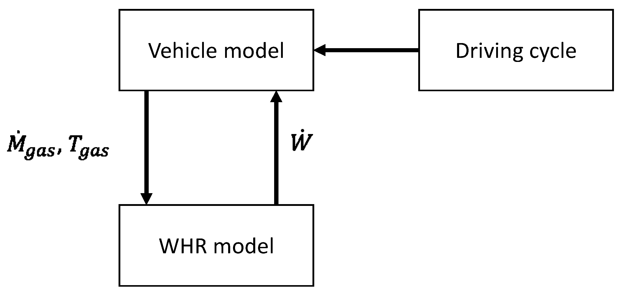
4. Simulations of the Various Waste Heat Recovery Technologies

4.1. Simulation Parameters

This study focusses on two spark ignition engines. The first one is an atmospheric engine whereas the second one is turbocharged. Simulation models are used with experimental data on a New European Driving Cycle (NEDC) Driving Cycle, a driving cycle in which every car is evaluated for emissions and consumption. Some data have also been used for those engines on a Worldwide harmonized Light vehicles Test Procedures (WLTP) Driving Cycle. That cycle is said to be the future normalized cycle used for the evaluation of the emission and the fuel consumption. It is more representative of real world vehicle operation where accelerations are higher than the ones of the NEDC driving cycle. Therefore there is more energy released in the gas in the WLTC cycle.
The simulation model of the engine was previously built under a Simulink environment. The vehicle model is composed of several blocks. The vehicle model evaluates the resistive force applied on the vehicle and includes different sources of losses such as transmission losses, gearbox losses, etc. The models follows the speed setting of the driving cycle by modifying the engine working conditions and the gearbox ratio. The losses have been quantified based on actual vehicle data. In order to evaluate the fuel consumption of the engine, a map has been provided to the simulation environment. That map represent the fuel consumption of the vehicle for a given torque and speed of the engine. The map has also been derived from experimental data. A flowchart of the whole simulation model is presented in Figure 7. The vehicle model provides the WHR model with the mass flow rate and the temperature of the gas at the exhaust of the gas after-treatment system.
The simulated vehicle is a mid-size vehicle of approximately 1500 kg for the atmospheric engine and 1500 kg for the turbocharged engine. Both engines work on gasoline fuel and show a displacement of 1.6 L.
The characteristics for each waste heat recovery technology are summarized in Table 1. An additional weight is included in the simulation and is varying according to the technology. Those additional weights are based on values found in the literature. Electric efficiencies of the electric generator for the Rankine cycle and the turbocompound have been set both to 90%.
Figure 7. Flowchart of the complete simulation model.
Energies 07 05273 g007
Table 1. Characteristics for the simulation of the different waste heat recovery technologies [15,27,39].
Additional parametersRankine cycleThermoelectricityTurbocompound
Additional weight (kg)201010
Converter efficiency (%)9090
The energy produced by any waste heat recovery technology is then completely reused in the vehicle. In order to reuse that energy, an electric motor is modeled by a constant efficiency and adds a boost of power to the engine shaft in order to reduce the power that has to be provided by the engine. Modeling an electric motor has been chosen in order to reduce the interdependence between the vehicle model and the waste heat recovery system model. Indeed, the engine speed would set the speed of the power generating machine.
Finally, all the following results are based on steady state simulation model. Despite the fact that those results do not include any dynamics, they still provide an interesting basis of comparison of different waste heat recovery systems.

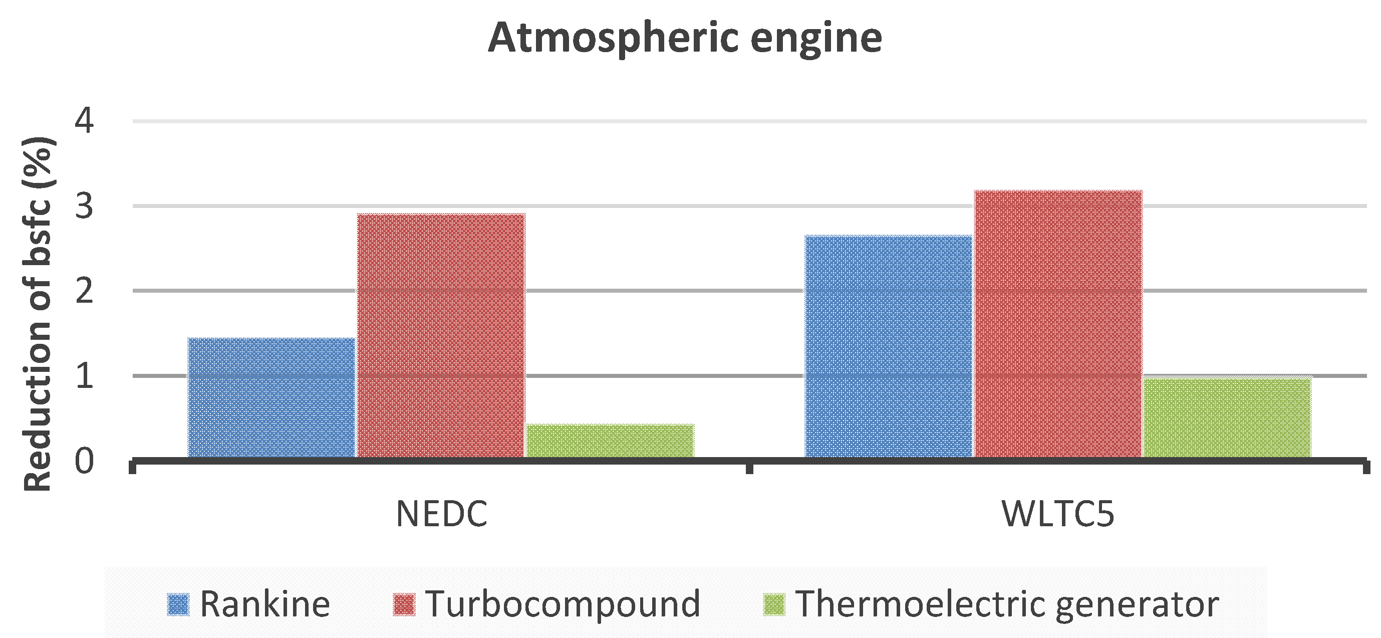
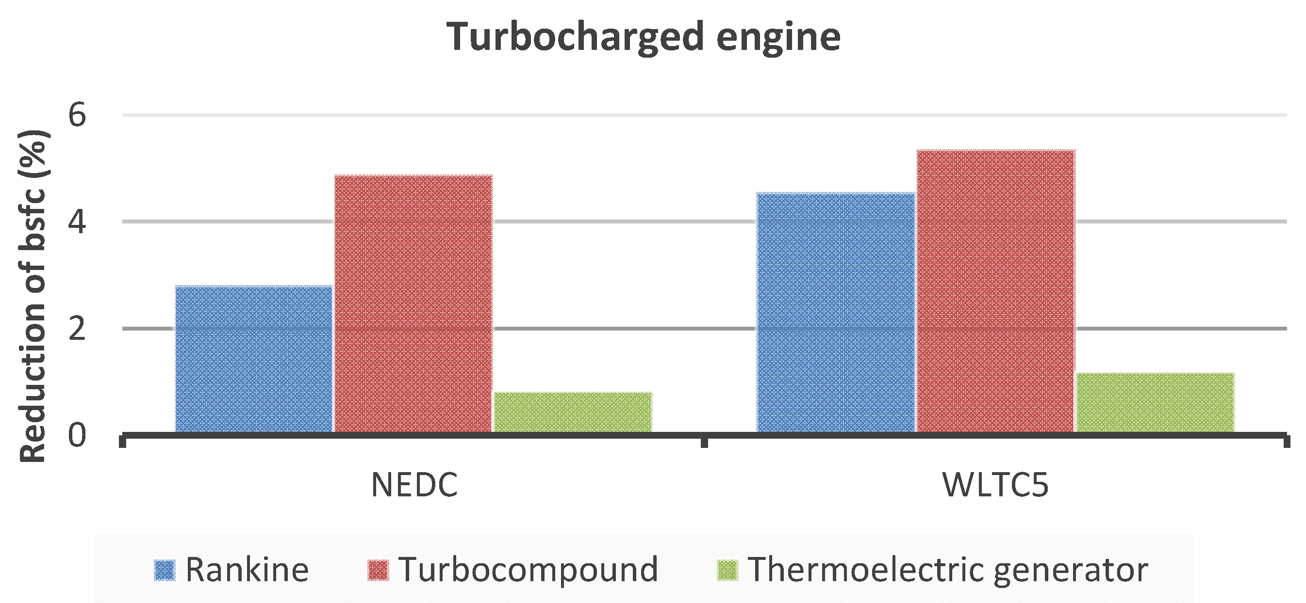
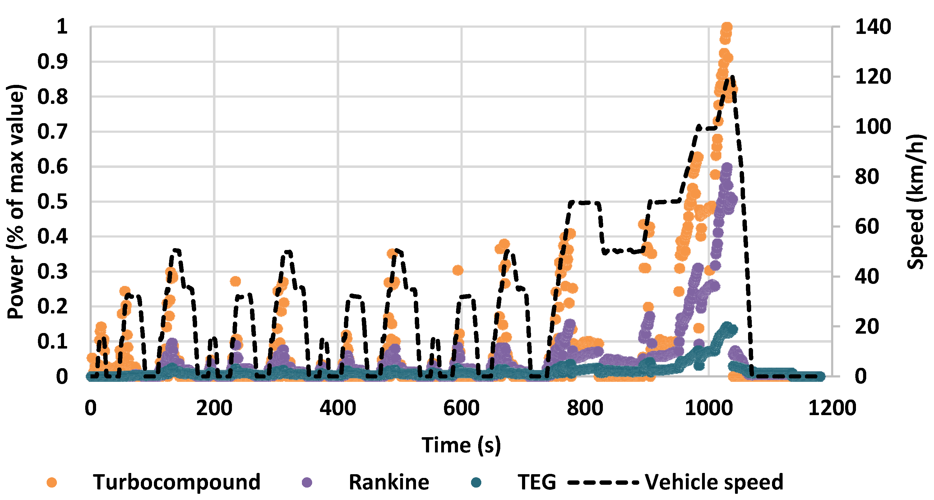
4.2. Simulation Results

The reductions in the fuel consumption of the vehicle for the different waste heat recovery technologies are presented in Figure 8 for an atmospheric engine and in Figure 8 for a turbocharged engine.
Figure 8. Reduction of fuel consumption for an atmospheric engine.
Energies 07 05273 g008
Figure 7 shows that the turbocompound provides the best results for each driving cycle. However, the turbocompound is affected by huge counterpressure at the engine exhaust. In addition to that, the exhaust backpressure is increased by the turbocompound and was not taken into account in the global evaluation of the fuel consumption. The mean back pressure of the turbocompound is 188 m bar in the NEDC Driving Cycle and 419 m bar in the WLTC Driving Cycle. Those pressures are relatively high and can introduce new issues or increase fuel consumption by increasing the indicated mean effective pressure in the IC engine.
On that same Figure, the Rankine cycle system is shown to be the second most efficient solution. The Rankine cycle decreases the fuel consumption as much as the turbocompound in the WLTC driving cycle. The mean produced power by the Rankine cycle is less than that of the turbocompound, as shown in Figure 7, because the Rankine cycle is more often used than the turbocompound. The Rankine cycle is able to recover energy for 64% of the time in the NEDC and for 71% in the WLTC. Compared to that, the turbocompound is barely used with the atmospheric engine with only 19% and 35% of the time for the NEDC and the WLTC respectively. Thermoelectricity shows the smallest reduction but has the highest time of use. The thermoelectric generator can be used almost all the time, but the power produced is rather low.
Figure 9 shows the results in the reduction of fuel consumption for a turbocharged engine. Firstly, the general conclusion is that the improvement is higher due to the higher mass of the vehicle that leads to higher working conditions of the engine. Turbocompounding offers the best performance for the NEDC and the WLTC cycles. Trends for both engines are similar, but a turbocharged engine discharges exhaust gases with a higher mass flow rate, resulting in a higher energy content of those gases. Therefore, reduction of fuel consumption is higher for the turbocharged engine.
Besides its increased weight, the Rankine cycle system offers acceptable performance with low backpressure depending on how well the evaporator is designed. It has also to be noticed that despite a very small fuel consumption reduction, the performance is not particularly high and is mostly due to the partial load conditions of the engine.
Figure 9. Reduction of fuel consumption for a turbocharged engine.
Energies 07 05273 g009
Some interesting results are also presented in Figure 10. The behavior of each system all along the driving cycle can be seen. First, it can be noticed that turbocompound shows the highest produced power but also the less frequent utilization. Turbocompound is mostly used in the acceleration phase of the vehicle and is almost never used otherwise. The reason is that the turbine of the turbocompound converts kinetic energy of the exhaust gas and therefore when the exhaust gas mass flow rate is too low, the turbine is not active, resulting in a low mean produced power.
Figure 10. Evolution of the normalized produced power of a turbocharged engine in function of the time with the speed profile of the driving cycle.
Energies 07 05273 g010
Then, Rankine cycle shows a high produced power, slightly less than turbocompound, and is more frequently used that turbocompound. Rankine cycle can be used in the acceleration phase but not only then. The Rankine cycle is also not active during the start-up phase of the engine. The exhaust gas contains too little energy and the criterion set in the model excludes those points. However, depending on how precisely the mass flow rate of the working fluid can be controlled, the energy contained in the exhaust gases at those times can still be harvested even if the temperature is very low. Rankine cycle shows better utilization than the turbocompound mostly because it does not rely only on the mass flow rate as the turbocompound does. Finally, the thermoelectric generator produces the less amount of power and the most frequent utilization. The thermoelectric generator has the advantage of only requiring a temperature difference and is less affected by the mass flow rate of the exhaust gases.

5. Conclusions

A complete state of the art review of the main technologies to recover waste heat energy in the exhaust gases of a light duty vehicle engine has been provided. As a conclusion to that state of the art, major drawbacks of those technologies have been pointed out and several relevant performance indicators have been compared: efficiency, cost, technical maturity, packaging and weight to power ratio.
The second part of this article focuses on the evaluation of the performance of three of those technologies on two different gasoline engines considering two different driving cycles. This evaluation is based on simulation. The models of three waste heat recovery systems have been built and calibrated based on measurement data.
The results presented in this article only rely on quasi-steady state models. Thus, the results presented here are not totally representative of the reality. It is very well known that passenger car engines have a very transient behavior. However, those results already show trends of each technology of waste heat recovery and allow one to draw early conclusions. Finally, such systems show benefits to achieve CO2 emission goals and, looking at the R&D trends, waste heat recovery should be introduced in the next few years on the market.

Author Contributions

All authors contributed to the work in this manuscript. Ludovic Guillaume helped to the Rankine cycle modeling. Mouad Diny provided some help on the thermoelectric model and an industrial overview of the results. Hamid Zaïdi reviewed and revised the paper. Vincent Lemort helped with precious advices regarding the modeling of the systems and the analysis and presentation of the results. Arnaud Legros conducted the exhaustive state of the art, built all the models, carried out all the results and wrote the paper.

Nomenclature

Symbols

B o Boiling number
C Constant
C ˙ m i n Minimum capacitive flow rateJ/s.K
c p Constant pressure specific heat capacityJ/kg.K
D h Hydraulic diameterM
h Specific enthalpyJ/kg.K
H T C Heat transfer coefficientW/m²K
k Thermal conductivityW/mK
M ˙ Mass flow rateKg/s
N T U Number of transfer units
P r Prandtl number
Q ˙ Heat transfer rateW
R Thermal resistancem2K/W
R e Reynolds number
T TemperatureK
W ˙ Power W
Z T ¯ Mean figure of merit

Subscripts

1POne phase
2PTwo phases
ColdCold side
CoolantCoolant side
ExExhaust
GasGas side
HotHot side
IsIsentropic
PpPump
SuSupply
wfWorking fluid side

Greek letters

γ Heat capacity ratio
ϵ Effectiveness
η Efficiency
ω Capacitive mass flow rate ratio

Conflicts of Interest

The authors declare no conflict of interest.

References

  1. Daccord, R.; Melis, J.; Kientz, T.; Darmedru, A.; Pireyre, R.; Brisseau, N.; Fonteneau, E. Exhaust heat recovery with rankine piston expander. In Proceedings of ICE Powertrain Electrification & Energy Recovery, Rueil-Malmaison, France, 28 May 2013.
  2. Mexico Light-Duty Vehicle CO2 and Fuel Economy Standards; International Council On Clean Transportation: Berlin, Germany, 2012.
  3. Borgne, G.L. Le Véhicule 2L/100km: Un Grand Programme D'avenir Mobilisateur; Ateliers de la filière automobile: Paris, France, 2013. (In French) [Google Scholar]
  4. Chammas, R.E.; Clodic, D. Combined cycle for hybrid vehicles. In Proceedings of SAE World Congress, Detroit, MI, USA, 11–14 April 2005.
  5. Conklin, J.C.; Szybist, J.P. A highly efficient six-stroke internal combustion engine cycle with water injection for in-cylinder exhaust heat recovery. Engery 2010, 35, 1658–1664. [Google Scholar]
  6. Endo, T.; Kawajiri, S.; Kojima, Y.; Takahashi, K.; Baba, T.; Ibaraki, S.; Takahashi, T.; Shinohara, M. Study on maximizing exergy in automotive engines. SAE Technical Paper 2007. [Google Scholar] [CrossRef]
  7. Gardner, D.L.; Howard, C.Q. Waste-heat-driven thermoacoustic engine and refrigerator. In Proceedings of Acoustics 2009, Adelaide, Australia, 23–25 November 2009.
  8. Fu, J.; Liu, J.; Yang, Y.; Ren, C.; Zhu, G. A new apporach for exhaust energy recovery of internal combustion engine: Steam turbocharging. Appli. Therm. Eng. 2013, 52, 150–159. [Google Scholar] [CrossRef]
  9. Sirot, F. Les moteurs à cycles asymétriques, une approche énergétique efficiente en phase avec les nouveaux enjeux technico-économiques: Cas du moteur 5 temps SWG. In Proceedings of Utilisation rationnelle de l'énergie et environnement, Paris, France, 26 March 2013. (In French)
  10. Douglas-self. The Kitson-Still Steam-Diesel Locomotive. Available online: http://www.douglas-self.com/MUSEUM/LOCOLOCO/kitson/kitsonst.htm (accessed on 6 March 2012).
  11. Toom, R. Waste heat regeneration systems for internal combustion engines. In Proceedings of Global Powertrain Congress, Berlin, Germany, 18 June 2007.
  12. Patel, P.S.; Doyle, E.F. Compounding the truck diesel engine with an organic rankine cycle system. In Proceedings of Automotive Engineering Congress and Exposition, Detroit, MI, USA, 23–27 February 1976.
  13. Oomori, H.; Ogino, S. Waste heat recovery of passenger car using a combination of rankine bottoming cycle and evaporative engine cooling system. SAE Technical Paper 1993. [Google Scholar] [CrossRef]
  14. Freymann, R.; Strobl, W.; Oblieglo, A. The turbosteamer: A system introducing the principle of cogeneration in automotive applications. MTZ Worldw. 2008, 69, 20–27. [Google Scholar]
  15. Freymann, R.; Ringler, J.; Seifert, M.; Hörst, T. The second generation turbosteamer. MTZ Worldw. 2012, 73, 18–23. [Google Scholar] [CrossRef]
  16. Leduc, P.; Smague, P. Rankine system for heat recovery: An interesting way to reduce fuel consumption. Ing. L'automob. 2013, 826, 34–39. [Google Scholar]
  17. Dyer, L.H. Internal Combustion Engine. U.S. Patent 1,339,176, 5 April 1920. [Google Scholar]
  18. Birkholtz, U.; Grob, E.; Stohrer, U.; Voss, K.; Gruden, D.O.; Wurster, W. Conversion of waste exhaust heat in automobile using FeSi2 thermoelements. In Proceedings of 7th IEEE International Conference on Thermoelectric Energy Conversion, Arlington, VA, USA, 16–18 March 1988.
  19. Takanose, E.; Tamakoshi, H. The development of thermolectric generator for passenger car. In Proceedings of 12th IEEE International Conference on Thermoelectrics, Yokohama, Japan, 9–11 November 1993.
  20. Ikoma, K.; Munekiyo, M.; Furuya, K.; Kobayashi, M.; Izumi, T. Thermoelectric Module and Generator for Gasoline Engin Vehicles. In Proceedings of 17th IEEE International Conference on Thermoelectrics, Nagoya, Japan, 24–28 May 1998.
  21. Ikoma, K.; Munekiyo, M.; Furuya, K.; Kobayashi, M.; Izumi, T. Thermoelectric generator for gasoline engine vehicles using Bi2Te3 modules. J. Jpn Inst. Met. 1999, 63, 1475–1478. [Google Scholar]
  22. Bass, J.C.; Elsner, N.B.; Leavitt, F.A. Performance of the 1 kw thermoelectric generator for diesel engines. In Proceedings of 13th International Conference on Thermoelectrics, Kansas City, MO, USA, 30 August–1 September 1995.
  23. Engines, W.A. Facts about the Wright Turbocompound. Available online: http://www.enginehistory.org/Wright/TC%20Facts.pdf (accessed on 10 March 2014).
  24. Hetting, C.; Tunberg, A. Le camion Scania—Un routier centenaire. Scania World 2002. Available online: http://toolkitstatic.scania.com/scaniaworld/archive/pdf/ScaniaWorld_fr.pdf (accessed on 14 August 2014). (In French).
  25. Greszler, A. Diesel Turbo-Compound Technology. In Proceedings of DEER Confrerence, Dearborn, MI, USA, 4–7 August 2008.
  26. Nicolino, J.-F. Récupération D'énergie par Tubocompound: Applications à la Compétition Automobile et à la Série. In Proceedings of Utilisation rationnelle de l'énergie et environnement, Paris, France, 3 April 2012. (In French)
  27. TIGERS. Available online: http://www.cpowert.com/Products/TIGERS (accessed on 16 December 2013).
  28. Romagnoli, A.; Bin-Mamat, A.; Martinez-Botas, R. Design and development of a Low Pressure Turbine (LPT) for Turbocompounding Applications Using RICARDO WAVE. In Proceedings of Ricardo Software User Conference and Workshops, Ludwigsburg, Germany, 9–10 April 2013.
  29. Vuk, C.T. Turbo compounding: A technology who’s time has come. In Proceedings of DEER Conference, Chicago, IL, USA, 21–25 August 2005.
  30. Petach, M.; Tward, E.; Backhaus, S. Design of A High Efficiency Power Source (HEPS) Based on Thermoacoustic Technology; NASA: Los Alamos, NM, USA, 2004. [Google Scholar]
  31. Backhaus, S.; Swift, G.W. A thermoacoustic-Stirling heat engine: Detailed study. J. Acoust. Soc. Am. 2000, 107, 3148–3166. [Google Scholar] [CrossRef] [PubMed]
  32. Wu, Z.; Man, M.; Luo, E.; Dai, W.; Zhou, Y. Experimental investigation of a 500 W traveling-wave thermoacoustic electricity generator. Chin. Sci. Bull. 2011, 56, 1975–1977. [Google Scholar]
  33. Struzyna, R.; Span, R.; Eifler, W. Utilization of waste heat through thermodynamic cycles. In Proceedings of 20th Aachen colloquium Automobile and engine technology, Aachen, Germany, 10–12 October 2011.
  34. Patterson, D.J.; Kruiswyk, R.W. An engine system approach to exhaust waste heat recovery. In Proceedings of DEER Conference, Detroit, MI, USA, 13–16 August 2007.
  35. Morrison, O.; Seal, M.; West, E.; Connelly, W. Use of a thermophotovoltaic generator in a hybrid electric vehicle. In Proceedings of Thermophotovoltaic Generation of Electricity: Fourth NREL Conference, Denver, CO, USA, 11–14 October 1999.
  36. Bernhart, W. Trends in ICE-Technologies. In Proceedings of Automotive Megatrends, Dearborn, MI, USA, 19–20 March 2013.
  37. Baker, H.; Cornwell, R.; Koehler, E.; Patterson, J. Review of low carbon technologies for heavy goods vehicles—Annex 1. Available online: http://www.ukpia.com/Libraries/Download/Review-of-Low-Carbon-Technologies-for-HGVs.sflb.ashx (accessed on 11 August 2014).
  38. Pattison, N. Automotive world megatrends. In Proceedings of Automotive Megatrends, Brussels, Belgium, 12–13 November 2013.
  39. Fairbanks, J.W. Automotive thermoelectric generators and HVAC. In Proceedings of DEEE Conference, Dearborn, MI, USA, 16–19 October 2012.
  40. Seal, M. Quiet, Clean, Multi-Fueled, Multi-Kilowatt Thermophotovoltaic Generator; Western Washington University: Bellingham, WA, USA, 2000. [Google Scholar]
  41. Hsieh, Y.Y.; Lin, T.F. Evaporation heat transfer and pressure drop of refrigerant R-410A flow in a vertical plate heat exchanger. J. Heat Transf. 2003, 125, 852–857. [Google Scholar] [CrossRef]
  42. Lemort, V.; Quoilin, S.; Cuevas, C.; Lebrun, J. Testing and modeling a scroll expander integrated into an organic Rankine cycle. Appli. Therm. Eng. 2009, 29, 3094–3102. [Google Scholar]
  43. Legros, A.; Guillaume, L.; Diny, M.; Zaidi, H.; Lemort, V. Experimental investigations of the valorization of the exhaust waste heat of a gasoline engine based on a rankine cycle. In Presented at FISITA World Automotive Congress, Maastricht, The Netherlands, 3 June 2014.
  44. Pettersson, F. Simulation of a Turbo Charged Spark Ignited Engine. Master Thesis, Linköpings Universitet, Linköping, Sweden, 2000. [Google Scholar]
  45. Pacejka, H. Tire and Vehicle Dynamics; Butterworth-Heinemann: Oxford, UK, 2012. [Google Scholar]

