1. Introduction
When considering the risks and opportunities that lie for humanity in the nearest future, it becomes clear that energy is a main topic to discuss. Indeed, human beings on Earth require an ever-rising amount of resources, due to the increase of world population which, not only has already surpassed the 7000 million inhabitants mark [
1], but also is expected to become more than 8200 million in 2030 [
2] and 9300 million by 2050 [
3]. At the same time, there is a gradual shift in the way the Earth is populated, with an ongoing trend of rural exodus and urban migration. This trend has become so noticeable that nowadays there are more people living in cities than in the countryside, something that has never happened before [
4]. This change creates new challenges in terms of infrastructures, transport and energy management that must be solved from a sustainability-based point of view. In the end, an optimization of energy usage must be sought so as to guarantee that the needs of present and future population are covered.
As far as energy and electricity are concerned, one major development to take into account is the “Smart Grid”. Although it has been defined in different manners (for example, as “sophisticated, digitally enhanced power systems where the use of modern communications and control technologies allows much greater robustness, efficiency and flexibility than today’s power systems” [
5] or as an electrical power infrastructure capable of making intelligent decisions about the status of electrical power systems [
6]), there are two features that are inherent to it: energy saving as a clear target—using mechanisms that tend to regulate and incentive the reduction of energy usage at peak hours, such as Demand Side Management [
7] and an extensive use of Information and Communication Technologies—effectively recognized by several standards, as IEEE P2030, so as to guarantee seamless communication among electricity employment stages [
8]. Demand Side Management can also be used for long-term energy consumption planning, as it is likely to establish policies in load balance and load usage for extended periods of time, thus resulting in the ability to forecast energy consumption and deal with it in a less unpredictable manner. From our point of view, the Smart Grid can be defined as a conventional power grid that becomes enhanced by the use of Information and Communication Technologies, allowing it to perform complex and innovative functionalities bent on energy savings and information management platform. Therefore, end users become able to consume electricity in a more efficient manner, stretching the use of energy resources for longer periods of time.
Typically, a Smart Grid will involve different stakeholders. Among them, it is necessary to highlight the importance of the following:
Transmission System Operator (TSO): it is the provider of the conventional grid equipment, which is responsible for power transmission, especially when high voltage electricity is transferred;
Distribution System Operator (DSO): it is the entity that manages medium voltage transmission. Also, it usually behaves as the mediating actor between the TSO and the aggregator, selling the energy to the latter;
Aggregator: this company purchases the electricity that is sold by the DSO, and resells it to the end users that are going to consume it. However, they may be able to collect a share of energy by themselves;
“Prosumer”: while traditional energy consumers are present in the Smart Grid as well, they are also able to obtain energy from their own equipment (solar panels, small-sized windmills, etc.), thus becoming an actor able to produce and consume energy, hence the term “prosumer” (producer + consumer).
At the same time, there are several differing technologies involved in the Smart Grid; it can be argued that the most notorious ones are:
Distributed Energy Resources (DERs): they have been previously referred to as the equipment that a prosumer employs in order to obtain energy from its local environment. Commonly, these resources will be located at the user workplace or dwelling;
Advanced Metering Infrastructure (AMI): it is the equipment used for energy-related measurements (consumption, costs, etc.); it is usually placed at the end user’s surroundings;
Big Data: rather than being a hardware-based technology, Big Data is about the management and analysis of the significant amount of information that will be required within the Smart Grid, which will be advisable if services and applications are to be implemented satisfactory.
With a grid conceptually as old as one hundred years [
8], stakeholders of varying interests and heterogeneous technologies, information interchange at the ICT systems that belong to the Smart Grid becomes the next issue to deal with. Given the different nature of each of the actors, it is likely that information dealing with data requests or event triggering will be transferred in many different formats. Depending on the equipment manufacturer (for example, Siemens [
9] and Schneider [
10] have independent developments in this area), information may be transferred using one kind of data format (XML, JSON) or another; when used with equipment from other manufacturers, proprietary solutions with a low degree of compatibility and accessibility are prone to appear as well. This interoperability challenge is a major issue in the Smart Grid environment, ranging from what may be found in a microgrid when using power standards (Ustun
et al. [
11]) to a more holistic view comprising the whole Smart Grid [
12]. It is also faced when devices from different vendors are just collecting information from the environment [
13], something not dissimilar to what AMI is expected to do. We consider that the best way to fix this problem is designing a software layer that abstracts the heterogeneity of the hardware devices that are present in the environment and offer a homogenous-looking appearance to the application layer. This software layer is called “middleware”. Middleware has been defined in many ways; its usability ranges from a bridge between a system and an operator, capable of monitoring different pieces of equipment, to a tool employed to couple the functionalities of a Secondary Substation Node with the utility systems of a grid [
14]. In any case, the underlying idea is that it will hide the variety of the hardware devices used as part of the Smart Grid to ease the development of the applications handled by end users without expert knowledge of ICTs.
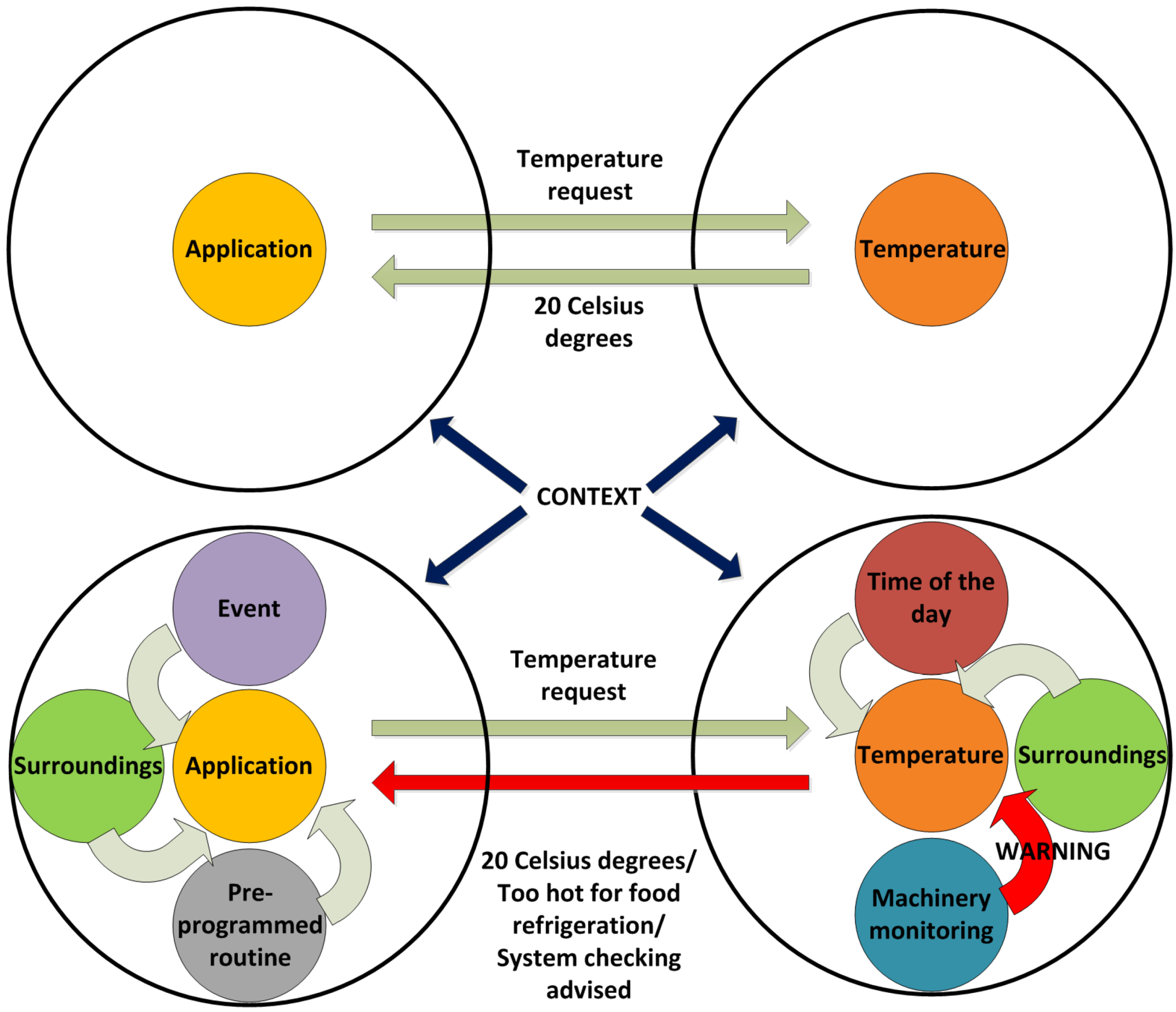
Information management is another major research topic that is critical for the correct performance of the Smart Grid, for it will offer the data that is required both for end user applications and right middleware management. Here, “data semantics” must be pinpointed; although not taking part just in the Smart Grid, it is foreseen to become of major importance for developments in this area. Semantics allows entities to become aware of the transferred data and consequently, knowledge can be inferred from the transmitted information. As a use case, if a request for temperature is made, and the result is “20 °C”, it is all the information that can be extracted in a conventional system. However, in a semantic environment, the obtained temperature will be evaluated, and if possible, actions will be considered, behaving as “20 °C is too hot for food refrigeration. It is suggested to check the systems” instead of the isolated temperature value. Commonly, ontologies will be taking great responsibility, as they are in charge of compiling the information about the entities that are part of the system. An ontology can be loosely described as a dictionary containing updated information about all the entities that are part of a system, along with all their interrelations and interactions. They are often represented in RDF standard format, which is not dissimilar to XML [
15]. Web Ontology Language is often used as a language to compose them, even when they are developed for a Smart Grid as an element of its architecture [
16].
Similarly, other system features come in handy for semantic data, such as “context awareness”: if data semantics is awareness of the information inferred from data, then context awareness can be deemed as the information that the system obtains becoming aware of its surroundings; it can also be defined as “the ability of computing systems to acquire and reason about the context information and adapt the corresponding applications accordingly” [
17]. In this way, context awareness turns into a facility that is exploited to the system advantage, working closely with semantics in order to infer information from a holistic perspective, as it has been represented in
Figure 1.
Figure 1.
Differences between a context-aware and a non-context-aware application.
Figure 1.
Differences between a context-aware and a non-context-aware application.
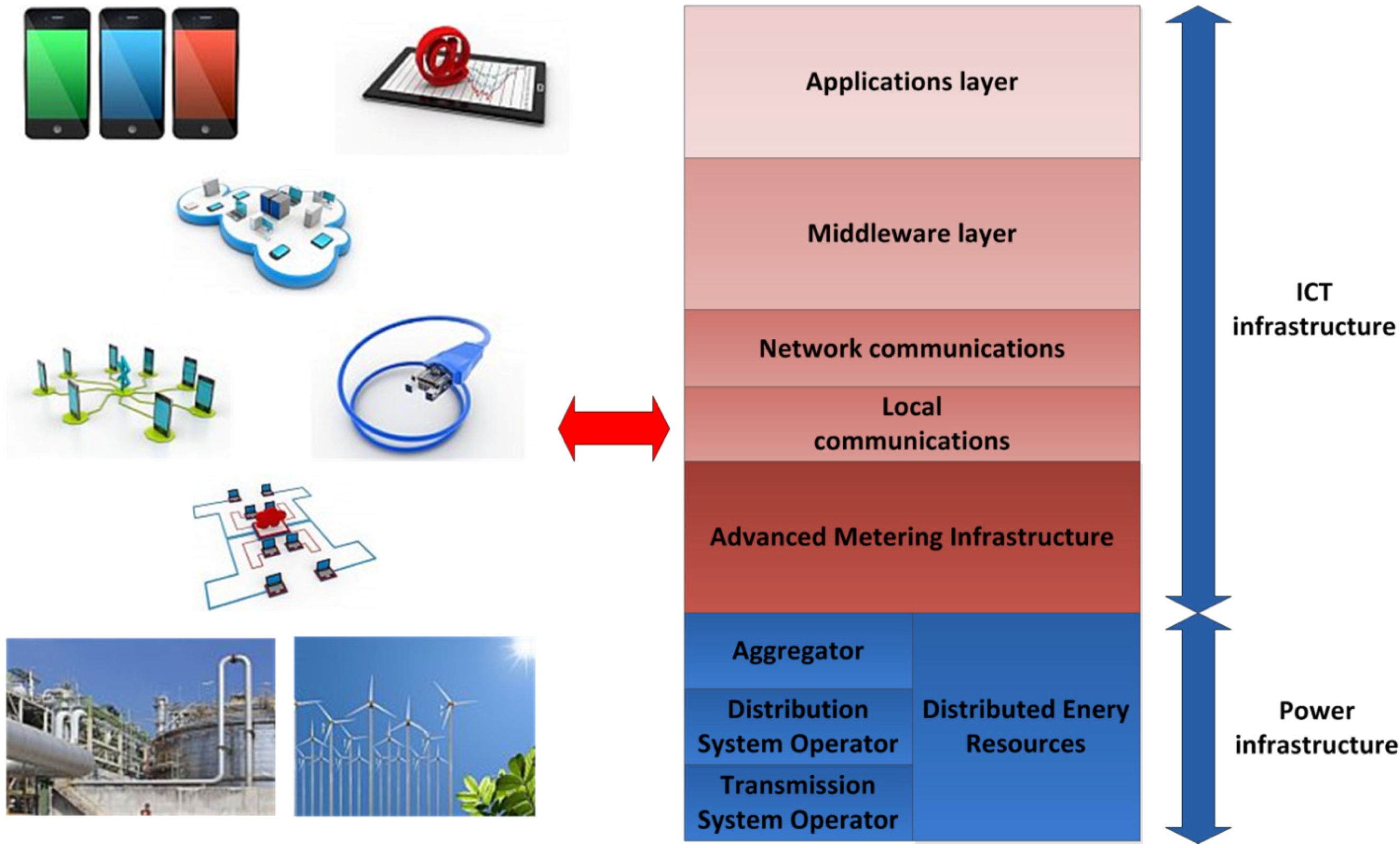
In the end, a Smart Grid system can be organized as the way represented in
Figure 2. There are two different areas of knowledge that must be considered according to its subjacent features: one related with power creation and transmission—consisting of all the equipment used to generate electricity, either from regular facilities as power plants, or Distributed Energy Resources—and another one related with Information and Communication Technologies (ICT). Additionally, a middleware layer is a useful optimization for information management in its domains.
Figure 2.
Layered overview of the Smart Grid
Figure 2.
Layered overview of the Smart Grid
Although there are a great number of developments involving information management as an unavoidable feature of the Smart Grid, they often fall short in taking into account the three different characteristics—in fact, non-functional requirements—that have been defined as critical in this introduction: Smart Grid focus, prominent information management layer and semantic capabilities for data treatment. There are several major reasons to choose these as the non-functional requirements as the scope of the solution shown in this paper:
Smart Grid focus guarantees that an optimized solution has been developed for the specific needs and services of this environment, such as Demand Side Management, Demand Response or energy consumption forecasting. Should an ICT-based architecture be ported from any other environment to the Smart grid, major changes are likely to be required, thus resulting in a more constrained system and additional adaptation efforts;
A prominent information management layer is a must-have if information is going to be transferred with efficiency, for it can be charged with the tasks typically related with data (request/response transfers, context awareness, entity registration, etc.). Alas, semantic capabilities are more easily added if they become located in a layer or component as this;
Semantic capabilities are a compelling addition to a Smart Grid-based architecture because they allow the system to have smarter capabilities: registration can offer more information about the entities involved, applications are able to implement more complex functionalities and the information semantics allows the system to learn new concepts that will improve the future performance of the system.
It should come as no surprise that an implemented proposal fully considering these features has been put forward in this paper, showing how the three defined non-functional requirements have been modeled, implemented and tested with actual devices and applications. The contributions of this paper can be summarized as presented below:
A semantic middleware architecture has been implemented from scratch for a microgrid encased in a Smart Grid. It does not only abstract hardware heterogeneity for the upper layers, but also has semantic features implemented which are capable of dealing with transmitted information according to its meaning (semantic storage of information, SPAQRL requests,
etc.). Also, while tests have been done using a microgrid model, it could be installed in several of them that altogether make a Smart Grid, provided that there is a coordination mechanism among the different microgrids (for example, multi-agent coordination for global information discovery [
18]);
This semantic middleware architecture has been developed using open software tools. Fuse ESB and Java programming language have been critical for the architecture implementation. In this way, the architecture can be modified by third party developers and further expanded, and its services can be learnt and utilized for research purposes;
The semantic middleware architecture presented here is distributed. It can be deployed in most of the devices that would be expected in a microgrid so as to have them cooperating simultaneously in different parts of the system. AMI open enough to have Fuse ESB-like components can have software
bundles installed, as shown in
section 5.
The remaining parts of the paper are organized as follows: a related works section is provided to evaluate the most notorious developments when considering Smart Grid focus, information management and semantics. Challenges found in these architectures, along with their evaluation, are described in
Section 3.
Section 4 describes thoroughly our proposal, depicting in an accurate manner all the elements that are important in it. Results of the testing activities that have been conducted are shown in
section 5. Conclusions and future works have been added in
section 6 and, to wrap the whole paper, acknowledgements and references have been added as the last two sections.
2. Related Works
When considering how information is managed in the Smart Grid, there are several facts that must be acknowledged. In spite of having a majority of the solutions created in an “ad hoc” fashion, some other information management platforms make use of a differentiated level that may or may not be shaped as a differentiated layer. In order to accurately evaluate how the studied proposals are matching and fulfilling the non-functional requirements (Smart Grid focus, information management prominence and semantic capabilities) presented here, a classification system has been developed. Depending on the maturity level of those requirements in each of the reviewed proposals, a score is given ranging from 1 to 5.
Table 1 is depicting the criteria used to grade how focused the proposals are on the idea of developing a proposal tailored for the needs of the Smart Grid. It has to be considered that, rather than the quality of the related works, what is being taken into account is their suitability to the non-functional requirements defined as of major importance. Therefore, chances are that the presented proposals are successfully matching the requirements that they were conceived with, but they struggle to adapt to the scenario and conditions presented here.
Table 1.
Grade description for Smart Grid focus.
Table 1.
Grade description for Smart Grid focus.
| Smart grid focus | Grade description |
|---|
| Grade: 5 | Information management platform conceived, designed and implemented for the Smart Grid from the beginning. Tests are provided by using a number of actual devices. Extensive information about its features is provided. |
| Grade: 4 | Information management platform conceived, designed and implemented for the Smart Grid almost from scratch. Tests are provided by using simulation tools rather than actual devices. |
| Grade: 3 | The information management platform has used a significant plethora of components prior to its usage in the Smart Grid, although the development has been tested and modified for the latter scenario. |
| Grade: 2 | Information management platform ported from another kind of system alien to the Smart Grid. Important information is missing. |
| Grade: 1 | The information management platform is not related with the Smart Grid / very scarce information is provided about its characteristics. |
Furthermore, as depicted in
Table 2, information management prominence has been graded as well. In this case, the relevance of any kind of refined procedure used for data collection and transfer able to cope with information of different origins has been considered, taking into account the quantity of detail and practicality of the information management proposals.
Table 2.
Grade description for Information Management Prominence.
Table 2.
Grade description for Information Management Prominence.
| Information management prominence | Grade description |
|---|
| Grade: 5 | Specific components designed and implemented in order to treat and enrich the data that is transferred throughout the system. Extensive information is provided about specific characteristics of the Smart Grid. |
| Grade: 4 | A detailed description about information management is provided, without having specific or prominent components used for them. Information is provided about specific characteristics of the Smart Grid |
| Grade: 3 | Data regarding information management is offered at an acceptable level: overall characteristics of the system (block diagrams, etc.) are provided, but there are less data about information treatment and transfer. |
| Grade: 2 | Provided data is a superficial description of the characteristics of information management without profound, detailed description. |
| Grade: 1 | No data available about management procedures or very scarce information is provided about its characteristics. |
Finally, as shown in
Table 3, the implementation of semantic capabilities has been graded as well, taking into account the information that was presented about them, as well as the depth of semantics and ontologies usage in the proposal.
Among the available information management platforms, the most relevant and updated are described and review in the following subsections.
Table 3.
Grade description for Semantic Capabilities.
Table 3.
Grade description for Semantic Capabilities.
| Semantic capabilities | Grade description |
|---|
| Grade: 5 | Semantic capabilities have been made part as part of the proposal since the first design stages and are used extensively as part of the proposal. Descriptions regarding used ontologies or ontology languages provided. |
| Grade: 4 | Semantic capabilities are added for prominent services. The amount of functionalities using them is significant. Detailed information provided about their characteristics and usage. |
| Grade: 3 | Semantics are used for a small set of functionalities. Information regarding semantics is offered at an intermediate level (theoretical concepts, description of the ontology). |
| Grade: 2 | Information regarding semantics is treated at a superficial level (theoretical concepts). Few information is provided about semantic capabilities |
| Grade: 1 | No semantic capabilities are provided in the proposal / very scarce information is provided about its characteristics. |
2.1. A Cloud Optimization Perspective
Xi Fang
et al. put forward an information management platform strongly based on cloud computing devoted to Smart Grid systems [
19]. Their proposal covers four different domains, namely “Smart Grid domain”, “cloud domain”, “broker domain” and “network domain”
. Smart Grid domain deals with three concepts: “Data Item” as an information object generated by some information sources, “Computational Project” as the component that uses Data Items and output information from previously finished tasks as inputs, and a “User” willing to access to the information related to Data Items or the outputs generated by the Computational Projects. Additionally, cloud domain consists of one or several clouds used for storage and computational services; different clouds may have different pricing policies depending on their particular needs. Broker domain will be the one responsible for mediation between the Smart Grid domain and the cloud domain whenever there are facilities that have to be interchanged. Finally, the network domain is involved with the network infrastructure and data transmission between any two former domains. The leading idea of this proposal is that the pricing policies of the Smart Grid, information provisioning and information storage will be offered as transparent facilities.
As far as cloud computing is concerned, it is a way to have a distributed solution that allows to store and execute complex and heavier operations than a standalone system would be able to perform. However, cloud computing systems tend to be more vulnerable in terms of security than other systems and must be equipped with extra mechanisms as Intrusion Detection Systems (IDSs) [
20]. Besides, little information is provided about how to deal with peripheral devices as AMIs or high level applications, and semantic treatment of data takes not part in the proposal.
Smart Grid focus: 4 (detailed description, simulated results). Information Management Prominence: 4 (detailed description). Semantic capabilities: 1 (no semantic capabilities).
2.3. Smart-Frame
Joonsang Baek
et al. offer their own ideas about an information management platform for the Smart Grid [
22]. As it was done with the first proposal, the authors rely on a cloud computing infrastructure to provide a platform for information management, especially conceived to deal with issues of the front end elements present in the system. The authors’ proposal is described according to three different viewpoints: “system architecture”, “logical components” and “information management”. System architecture explains how the system is divided into different regions that are managed by separated cloud computing centers, each of which can be set up either from a public or a private cloud. What is more, this service architecture exposes four different kinds of cloud computing services: Infrastructure-as-a-Service (IaaS), Platform-as-a-Service (PaaS), Data-as-a-Service (DaaS) and Software-as-a-Service (SaaS). Logical Components depict how services are classified according to four different clusters (information storage, general user services, control and management services and electricity distribution services), recognizing at the same time Infrastructure-as-a-Service as the backbone of the system. Information Management is focused on dataflow through the different entities of the proposal; a centralized service deals with the information flow by using a schedule defining particular sources and destinations for the information. In addition to the three different perspectives shown by the authors, an identity-based cryptographic solution is described to have a more trustworthy platform.
The presented proposal takes a more defined view on a platform (the authors refer to it as a “framework”) specifically built for a Smart Grid, but focuses primarily on the security functionalities that have been developed. Plus, semantic treatment of data is neglected, with no use of processed information in order to infer knowledge from the transmitted data. Finally, while the cloud computing paradigm offers a series of advantages compared to other distributed solutions, it also poses specific risks (security, accessibility) that must be considered as well.
Smart Grid focus: 4 (detailed description, simulated results). Information Management Prominence: 3 (proposal dealing mostly with security and cloud capabilities). Semantic capabilities: 1 (no semantic capabilities).
2.6. Service-Oriented Middleware for the Smart Grid
Liang Zhou
et al. put forward their own solution, providing a more middleware-oriented implementation [
27]. Here, middleware is used as a way to guarantee that the disparity of the underlying devices will not affect the availability of services within the system. What is more, a high degree of flexibility on the provided services is offered as well. The presented architecture is composed of three layers with different functionalities: a “user part” (mostly concerned about Quality of Service features that are going to be provided for the end users, as well as economy-driven applications), a “control part” (equipped with four different functions called fault report, security guarantee, user information management and power allocation that can be used for further developments), and a “transmission layer” (composed by communication, generation and distribution parts; this layer’s usual functionality will be power transmission from the generation plants to the distribution facilities through a group of substations).
This proposal is able to provide a clear layer devoted to information management for the Smart Grid that combines the advantages of having a distributed architecture and a dedicated management of the data flow from the applications and end user devices. Unfortunately, there is not a given way to use semantically enriched information; ontologies or mechanisms to provide advanced services, such as context awareness, have not been implemented either.
Smart Grid focus: 4 (detailed description, simulated results). Information Management Prominence: 5 (specific components designed and implemented). Semantic capabilities: 1 (no semantic capabilities).
2.7. Advanced Demand Side Management for the Future Smart Grid
Pedram Samadi
et al. offer their own work regarding Demand Side Management by using a mechanism design [
28]. It is assumed by the authors that end users have been equipped with “Energy Consumption Controllers (ECCs)” that are collecting information about consumer behavior. In this way, it is possible to have a more refined pricing methodology. The idea behind is that a “Vickrey-Clarke-Groves” mechanism can be used to improve the relation between the aggregate utility functions of the users and the total energy cost, which is capital for the performance of Demand Side Management within the Smart Grid. It must be highlighted that the main motivation for this piece of work is this DSM service; thus, the contributions that are claimed by the authors (Vickrey-Clarke-Groves usage for the Smart Grid, optimization problem formulation and its properties, especially truthfulness and efficiency, use case for their algorithm) are conceived entirely for it. Consequently, although this proposal fares fine in the area of DSM one of the most compelling services associated to the Smart Grid is not showing the overall perspective that is expected from an information management platform able to acknowledge data transfer among the different entities of the system. Alas, there is no information about how higher level capabilities (semantic web, context awareness,
etc.) are offered in this platform.
Smart Grid focus: 3 (extensive description of a single application). Information Management Prominence: 2 (information management as an afterthought). Semantic capabilities: 1 (no semantic capabilities).
4. Description of the Proposal
The architecture described in this document for the middleware uses as inputs the requirements defined in the e-GOTHAM project [
30] for a microgrid, and takes into account the IEEE 2030 Guide [
31] and CEN-CENELEC-ETSI SGAM [
32]. While the latter offers a holistic view of a completed microgrid, dividing its functionalities in five different layers (business, functional, information, computation and communication) it lacks an accurate description of what to use for data and information management, which is the main scope of our proposal.
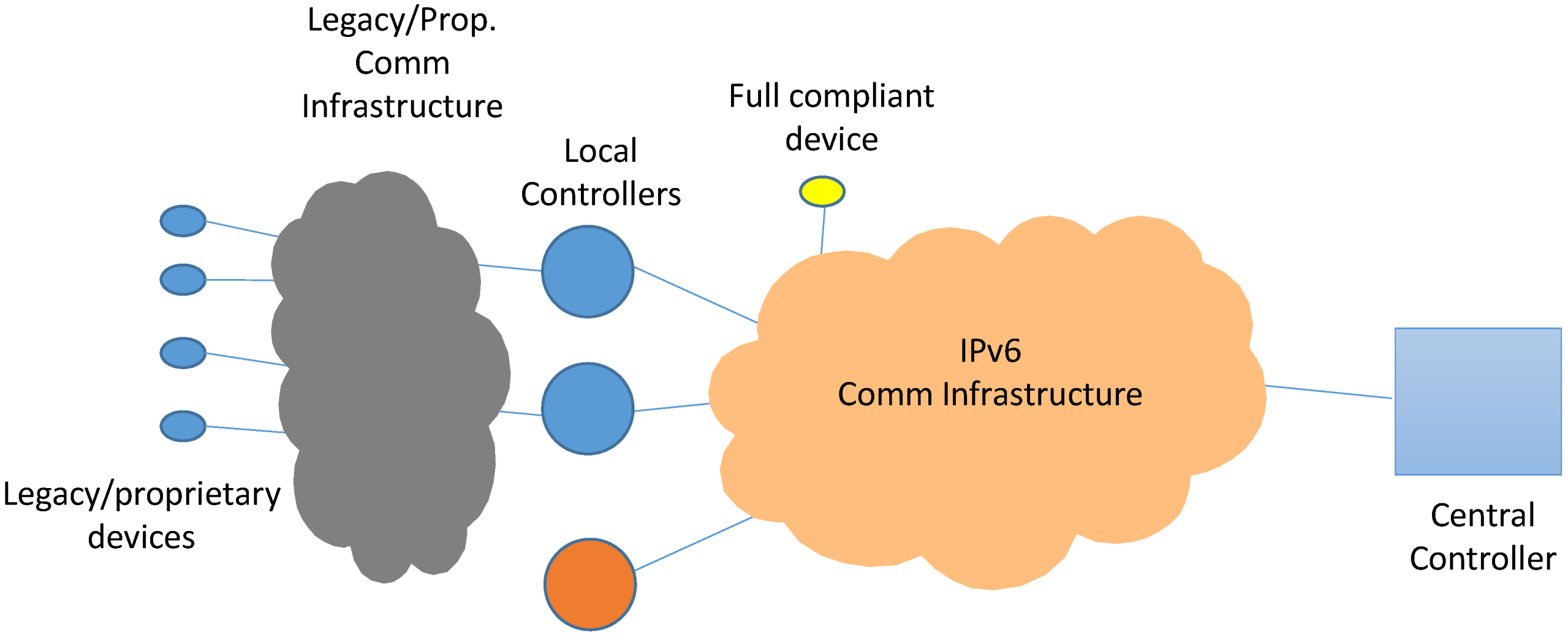
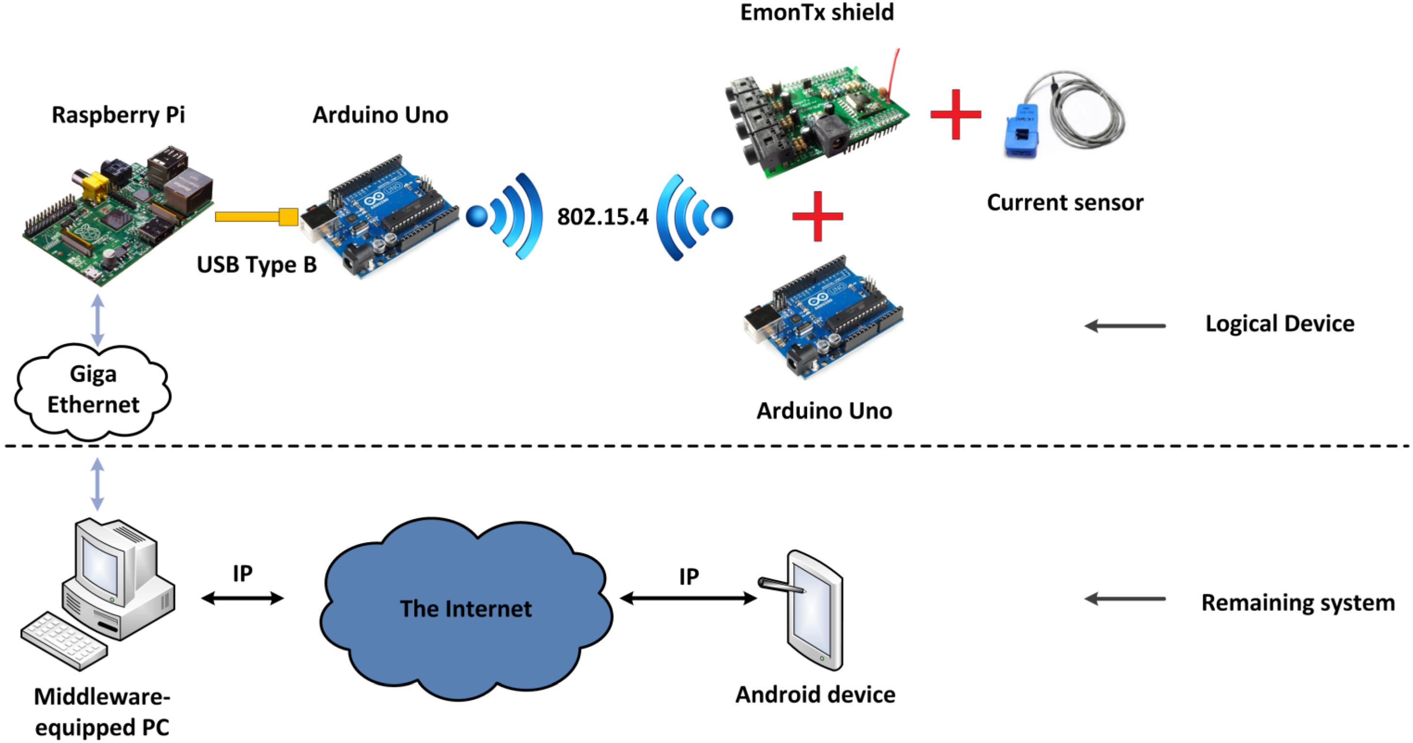
Rather than being deployed in one single device, the middleware architecture presented here is distributed in several physical elements, as illustrated in
Figure 3. These elements represent the ICT components of the microgrid used as part of the Smart Grid. A “Central Controller” (a hardware device involving functionalities that affect the whole microgrid are deployed) connected to several “Local Controllers” (simpler hardware devices including functionalities that involve one or several devices locally) and full compatible devices can be viewed. Some Local Controllers may act as bridges between legacy (already existing hardware pieces) or project proprietary (specifically developed) devices and the middleware architecture.
Figure 3.
System elements and networks
Figure 3.
System elements and networks
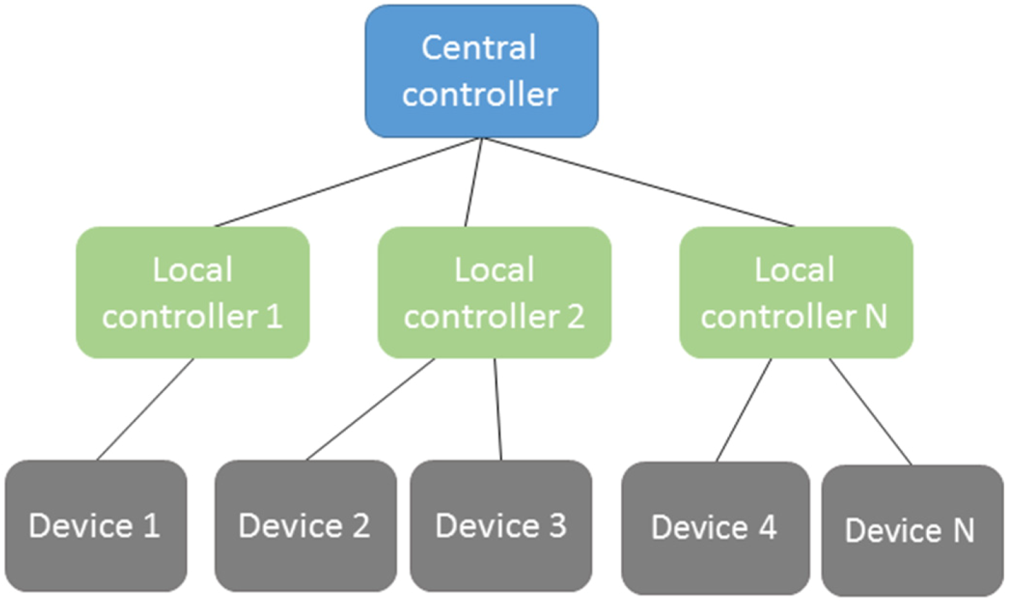
Figure 4 shows the hierarchy existing through the system elements. Usually, there is only one Central Controller; the amount and types of Local Controllers will depend on the scenario where the middleware is deployed. Devices will rely on Local Controllers.
Figure 4.
Middleware elements hierarchy.
Figure 4.
Middleware elements hierarchy.
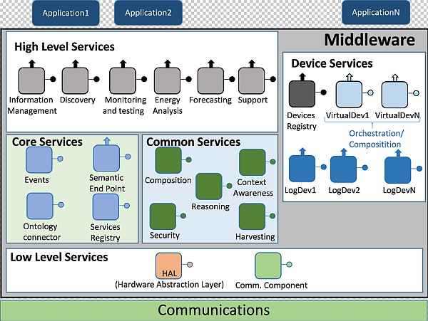
4.1. Architecture Presentation
When a middleware architecture had to be conceived for its usage in the Smart Grid, there were three main aspects that had to be considered for the implementation stage:
It required both SOA concepts to be used and a layered model for services divided and located in upper and lower levels;
It should be a distributed middleware architecture, where different hardware components may have several middleware parts deployed;
Semantic characteristics should be included. This was a critical challenge, for a particular ontology that would have the middleware architecture as its domain would be employed for semantic service and data registration, in order to infer knowledge from the information that is being transferred.
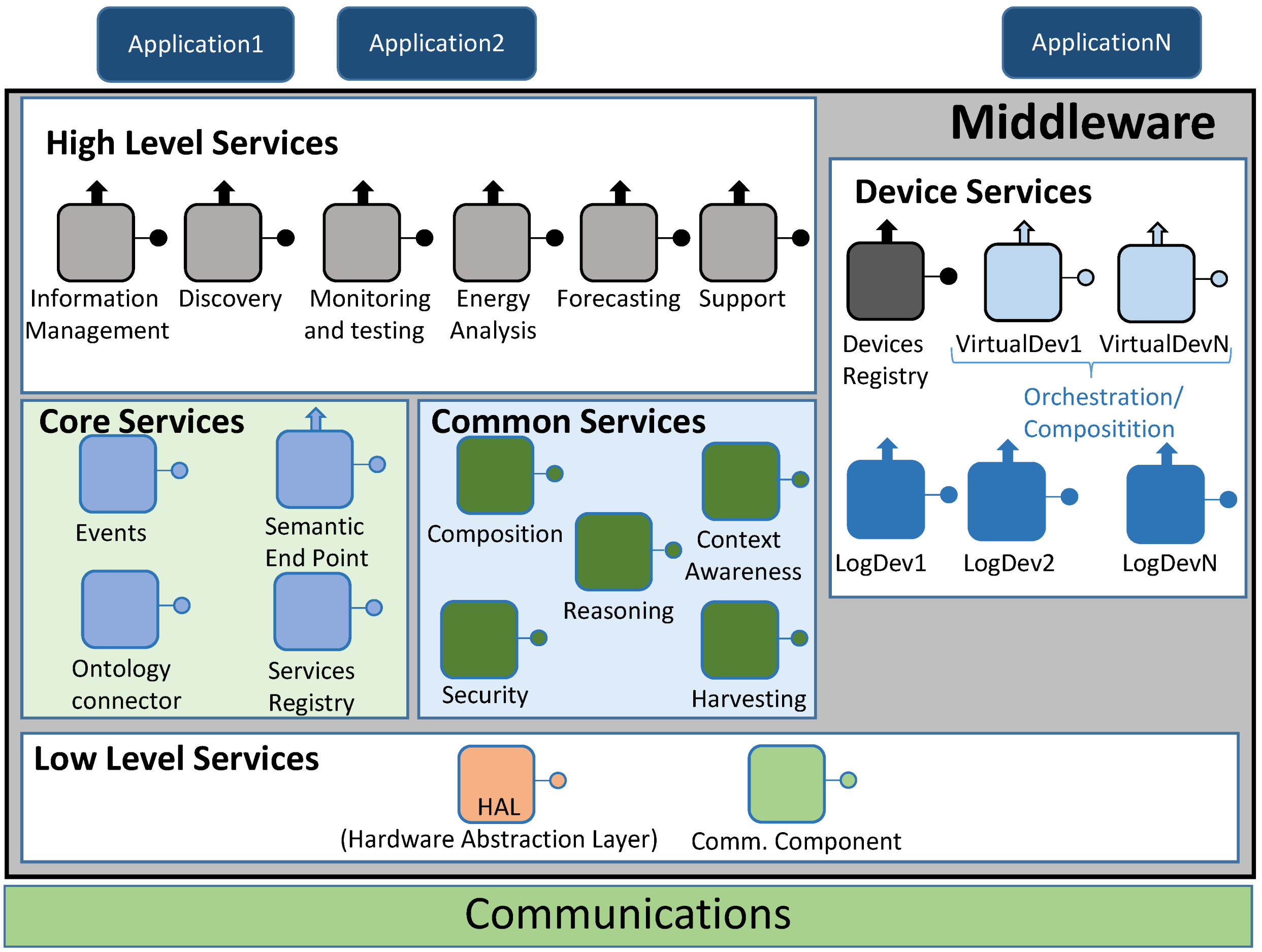
After several preliminary designs, a middleware architecture fulfilling the non-functional requirements defined in previous sections, along with its own major features, was elaborated, as depicted in
Figure 5.
Figure 5.
Middleware architecture.
Figure 5.
Middleware architecture.
Since a Smart Grid may be used for a plethora of different applications, related with data requests or information storage, dividing middleware functionalities by separated blocks—in a divide-and-conquer approach—was something to consider. In fact, it had been done before in the work presented by other authors as Liang
et al. [
33] or Sucic
et al. [
34], which was taking into account standards bound to the conventional power grid. Also, having components inside each of the blocks can be used as objects that manage different middleware functionalities, as described by Jin and Sung [
35].
4.1.1. High Level Services
These are the access points for applications at the upper layer that perform actions involving middleware properties. They can be regarded as the very first kind of services that are used in the middleware architecture from an upper point of view. Their functionalities are accessed via Representation State Transfer (REST) interfaces. Six services have been defined:
Information Management. It checks whether the information that has been retrieved by the middleware as an answer to a request matches the structure of the inner service ontology that the architecture is using;
Discovery. It is used to let the end user know what services are available, both in the middleware architecture and related to the hardware devices that are part of the system;
Monitoring and testing. It is used as a way to test the current status of the services that can be employed. Besides, it will be the most usual high level service to be executed when a pilot interface is managed;
Energy analysis. When requests involving specific data about energy are done, this high level service will come in handy to direct the data request;
Forecasting. Much like energy analysis, this high level service will be used whenever there is a request related with forecasting information;
Support. This high level middleware service is conceived for ancillary functionalities that are particular of the hardware device where the middleware architecture is deployed. If the monitoring and testing component is not enough by itself, Support high level service may be used as well.
4.1.2. Core Services
The services that are part of this block are the most critical of the ones taking part in the middleware architecture, as they have functionalities (semantic information treatment, service registry) that middleware cannot do without. The ones that have been identified as mandatory are as follows:
Events. As the middleware architecture used may use protocols that follow a publish/subscribe paradigm (for example, Advance Message Queuing Protocol or AMQP), it is useful to have a component to handle this sort of communications;
Semantic Endpoint. It offers compatibility between devices that do not use the middleware ontology and the remaining parts of the middleware architecture;
Ontology connector. It is used as a way to map the information retrieved from the devices and services into a semantic-compliant data model used within the middleware architecture;
Service Registry. Its main functionality is the registry of the services that, instead of being obtained from outer devices, are part of the middleware. Besides, they will be semantically registered by means of the operations made by the Ontology Connector.
4.1.3. Device Services
In this middleware block, all the devices (sensors and actuators) connected to the system have a logical representation in the middleware architecture based on their most important features and capabilities. This representation is named “Logical Device”. Logical Devices can be implemented on an IP-connected piece of equipment as long as the device hardware can run a mandatory minimum part of the middleware. For those devices incapable of implementing any part of the middleware (due to their low capabilities or any other constraining reason) the associated Logical Device will be implemented either in the Central or the Local Controller. Creation of Logical Devices allows the usage of the service ontology to describe in a complete manner the physical devices characteristics and to registry these elements in the device semantic database for later discovery and use. Three types of services have been enumerated here:
Devices Registry. It carries out the actions required to register a Logical Device and integrate it as part of the whole deployment. In addition to that, it will keep a strong connection with the deployed Logical Devices by means of heartbeat messages that will be sent to the Device Registry service. It must be noted that since Device Registry will be used with device services and Service Registry with middleware services, they are using different pieces of information;
Logical Devices. Used to represent the hardware devices that take part in the whole system. They are also used as service containers, depending on the sensors and capabilities that physical devices are equipped with. In addition to encapsulate hardware device features, they also provide a way to be deployed as compressed files in Fuse ESB-friendly locations, as explained later. The inclusion of Logical Devices in the architecture was decided after considering the Virtual Entities and Services defined in Internet of Things Architecture (IoT-A) [
36];
Virtual Devices. Virtual Devices result by merging two or more Logical Devices into a single one that will offer composed services dependent on the ones provided by Logical Devices. For example, a Logical Device offering a “temperature” service, and another one providing a “humidity” service can be merged into a third, different one named “environmental conditions” service that can be used to evaluate to probability of getting moss plants in one room.
4.1.4. Common Services
While designing this middleware architecture, some common functionalities required for the correct performance of the applications used in the system would sprang up (data gathering, context awareness, service composition,
etc.) regardless of the differing characteristics of the latter. Thus, a block of services dealing with the ones most usually employed has been created, in order to tackle the functionalities most closely linked to the frequent data transfers and operations required. One major feature of this block is that despite the fact that some components of the other blocks may not be deployed in a particular scenario, all common services are likely to be needed, regardless of the middleware surrounding environment. Five services have been defined as the ones taking part here.
Composition. It becomes of major importance when Virtual Devices are formed, as it will be the one used for this task;
Context awareness. It will be responsible for using retrieved information about the current status of the overall system, taking into account if there is any faulty performance so as to fix it;
Reasoning. When required, it will work jointly with Context Awareness to provide decision making mechanisms;
Security. It is a component devoted to functionalities and extra needs involving security. It provides features as integrity, privacy or authenticity, albeit the extra features required in this component will have to be met at the application and/or hardware levels;
Harvesting. This service collects the information obtained from the Low Level services and transfers it to the upper layers of the middleware architecture.
4.1.5. Low Level Services
As opposed to the other services, the ones located at this block are more focused on outer parts of the middleware architecture, such as the communications layer, that are used to either establish connections with other devices or with other components of the distributed middleware. The two entities that have been located here are:
Hardware Abstraction Layer (HAL). Its main usage point is to abstract all the hardware-specific features that may be found as part of the hardware components of the deployment;
Communications component. It is the actual interface between the communications layer protocol and the middleware architecture. Depending on the protocol used outside the middleware, it may use interfaces adapted to the communications protocol used (Java Message Service or JMS, AMQP, etc.).
4.2. Implementation Software Facilities
Next subsections deal with the different software tools used to implement the described middleware architecture.
Section 4.2.1 is about Enterprise Service Bus;
section 4.2.2 offers information about the interfaces that have been used for software bundle communication. Finally,
section 4.2.3 describes the messages used for data interchange within the middleware
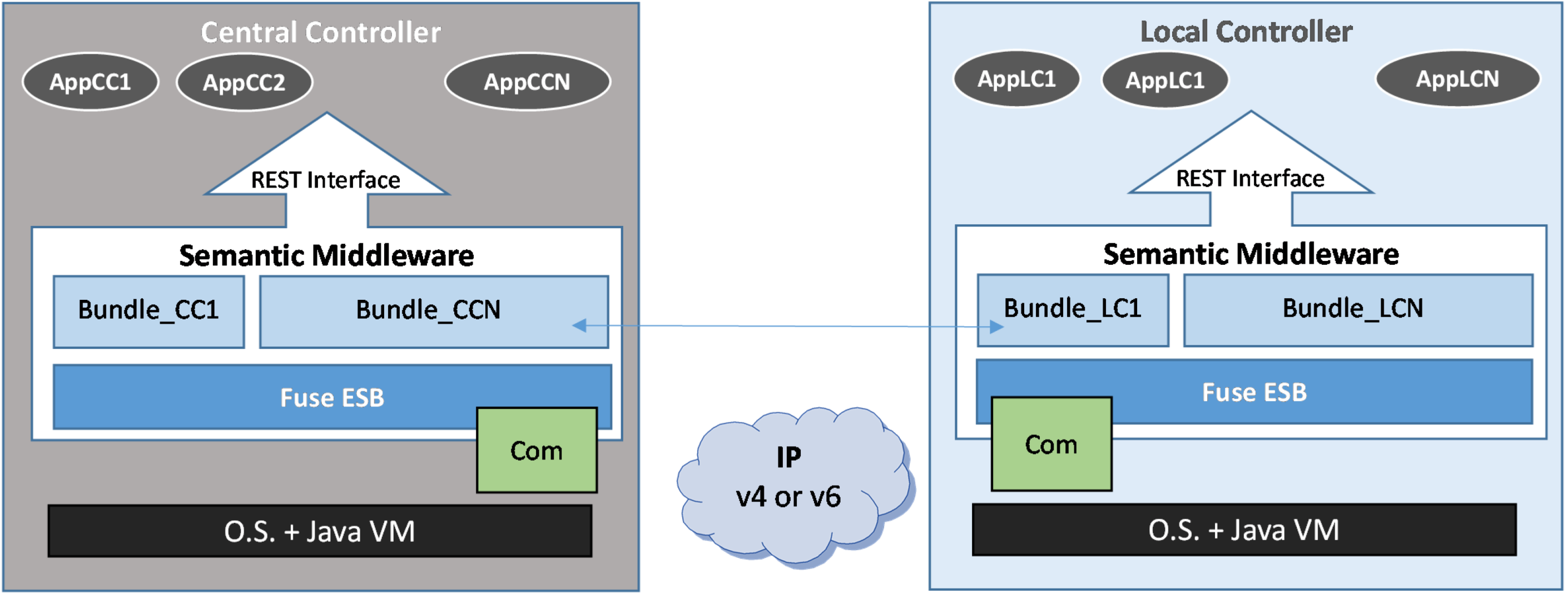
4.2.1. Fuse Enterprise Service Bus
An Enterprise Service Bus (ESB) was selected to deploy the semantic middleware architecture. ESB is a well-known software architecture that uses the bus as a message system to interchange information between the application components or, in ESB terminology, “bundles”. ESB also allows the implementation and publication of interfaces using several techniques in an affordable way in terms of computational resources. For the deployment that has been tested with real devices, JBoss Fuse ESB has been chosen; its inter-bundle communication capabilities can be used by the different services that are implemented [
37]. Another advantage of using Fuse ESB is that it performs its functionalities regardless of the protocols that are used at lower levels. For example, the access to physical devices and Local Controllers may also be driven by AMQP, an open standard application layer protocol for message oriented exchange [
38].
Thus, Fuse ESB can be regarded as the place where services are allocated and from where they can be provided.
Figure 6 depicts the general schema used for the implementation where the Central Controller and the Local Controller can be distinguished. Each of them is using distributed components that are being shared throughout the system. This structure comes in handy when different components are deployed in the Central (Device registry, Service registry, Ontology Connector,
etc.) and Local (Logical Device, Virtual Devices,
etc.) controllers. Applications running in the Central Controller are called AppCC1 (after Application at Central Controller number 1), AppCC2, and so on until AppCN. In the same way, applications belonging to the Local Controller are AppLC1 (after Application at Local Controller number 1), AppLC2, and so on until AppLCN. Both groups of applications use the services provided by the semantic middleware by means of RESTful interfaces.
Figure 6.
Enterprise Service Bus (ESB) extends the middleware to the Local Controller.
Figure 6.
Enterprise Service Bus (ESB) extends the middleware to the Local Controller.
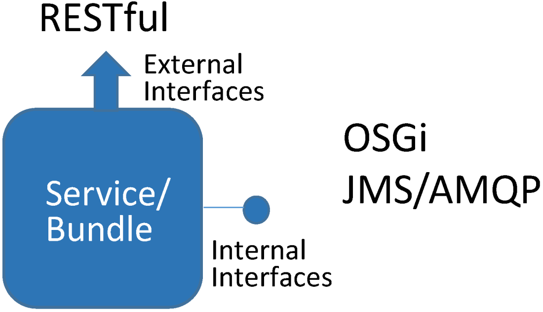
4.2.2. Service Interfaces Types
Figure 7 shows the interfaces offered by the middleware services. Two kinds of interfaces can be highlighted: internal and external. External interfaces are implemented by using a RESTful solution easy to handle with an ESB. Internal interfaces can be implemented using Open Service Gateway initiative (OSGi) interfaces (which are the native ones for Fuse ESB), JMS ones for asynchronous communications or AMQP bridged to the ESB using JMS capabilities. Interchanged messages are semantics-based messages codified in application layer meta-languages and languages as eXtensive Markup Language (XML) or JavaScript Object Notation (JSON).
Figure 7.
Interfaces for a high level service bundle.
Figure 7.
Interfaces for a high level service bundle.
4.2.3. Operation Protocol Messages
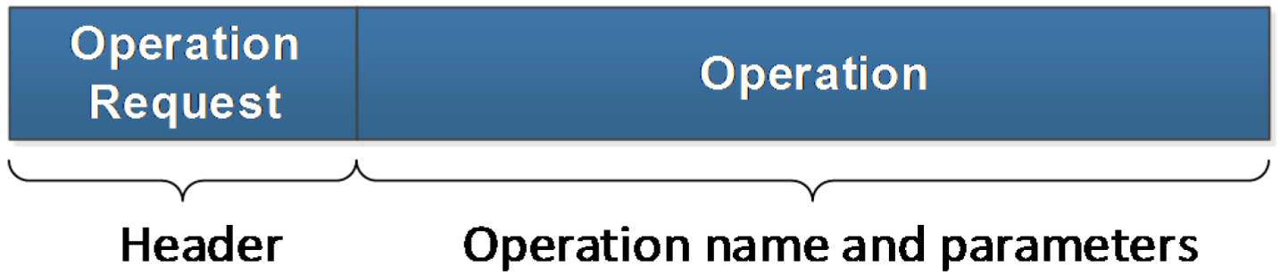
Regardless of the interface type—OSGi, JMS or AMQP—the interchanged messages share the same content and data fields. Two kinds of messages will be used in the operation protocol: operation request and operation response. They have been described in XML and contain the information of the operations. Operation messages are as follows:
Operation Request: by following a client-server paradigm, they will be sent from a Fuse ESB bundle acting as the client and received by a different bundle acting as the server. This message is made up by two fields:
- a)
Message type: it identifies what kind of message is being transferred;
- b)
Operation: this field encases the operation significant characteristics, namely the operation name and the input parameters. Furthermore, if any precondition is required for the operation to be triggered, it will be included as well.
The message appearance has been depicted in
Figure 8.
Figure 8.
Operation request message.
Figure 8.
Operation request message.
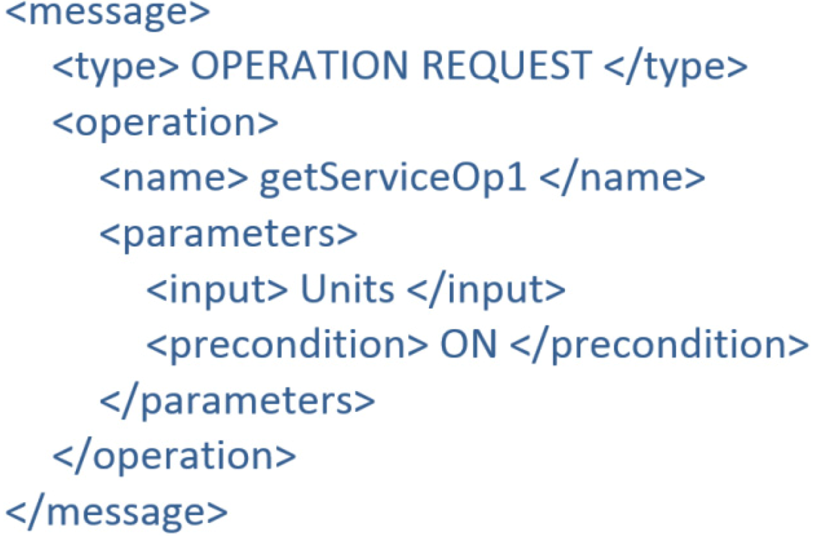
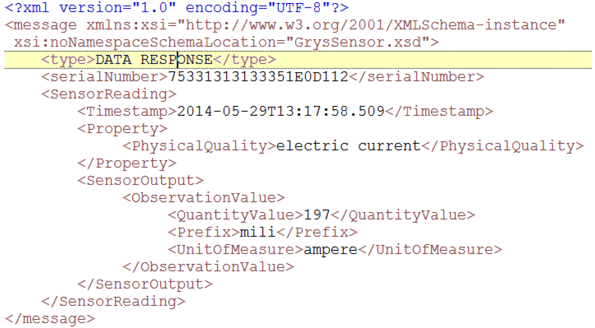
An example of the XML-formatted message that is being transmitted looks as presented in
Figure 9.
Figure 9.
Operation request eXtensive markup language (XML) example.
Figure 9.
Operation request eXtensive markup language (XML) example.
Operation Response: it is the natural counterpart of the Operation Request message, the one that is sent from the server bundle to the client one as an answer. As the former one, it is divided in two different parameters:
- a)
Message type: it identifies the kind of message that is being interchanged between bundles;
- b)
Operation: its content resembles Operation Request message, albeit the parameters that are contained are the output returned value instead of the inputs that were sent before.
4.3. Semantic Features
One of the project objectives has been achieving a middleware architecture with the innovative characteristic of inferring semantic knowledge from data. In order to integrate this characteristic in the semantic middleware architecture, a service-oriented ontology, where services from the middleware are semantically annotated in a repository, has been developed. Although the idea of having a “gluing” layer that uses a communication bus with semantic capabilities is not entirely new (Jeroen Famaey
et al. do indeed put it forward [
39]), so far it has not been fully implemented in a middleware architecture for Smart Grid environments. These semantic features allow easy information exchanges between different types of computers, devices or components employing several kinds of operating systems and application languages. Therefore, interoperability of heterogeneous information sources between different middleware components can be enabled by means of this ontology. In addition to that, the ontology provides a knowledge domain where the semantic data reusability becomes plausible.
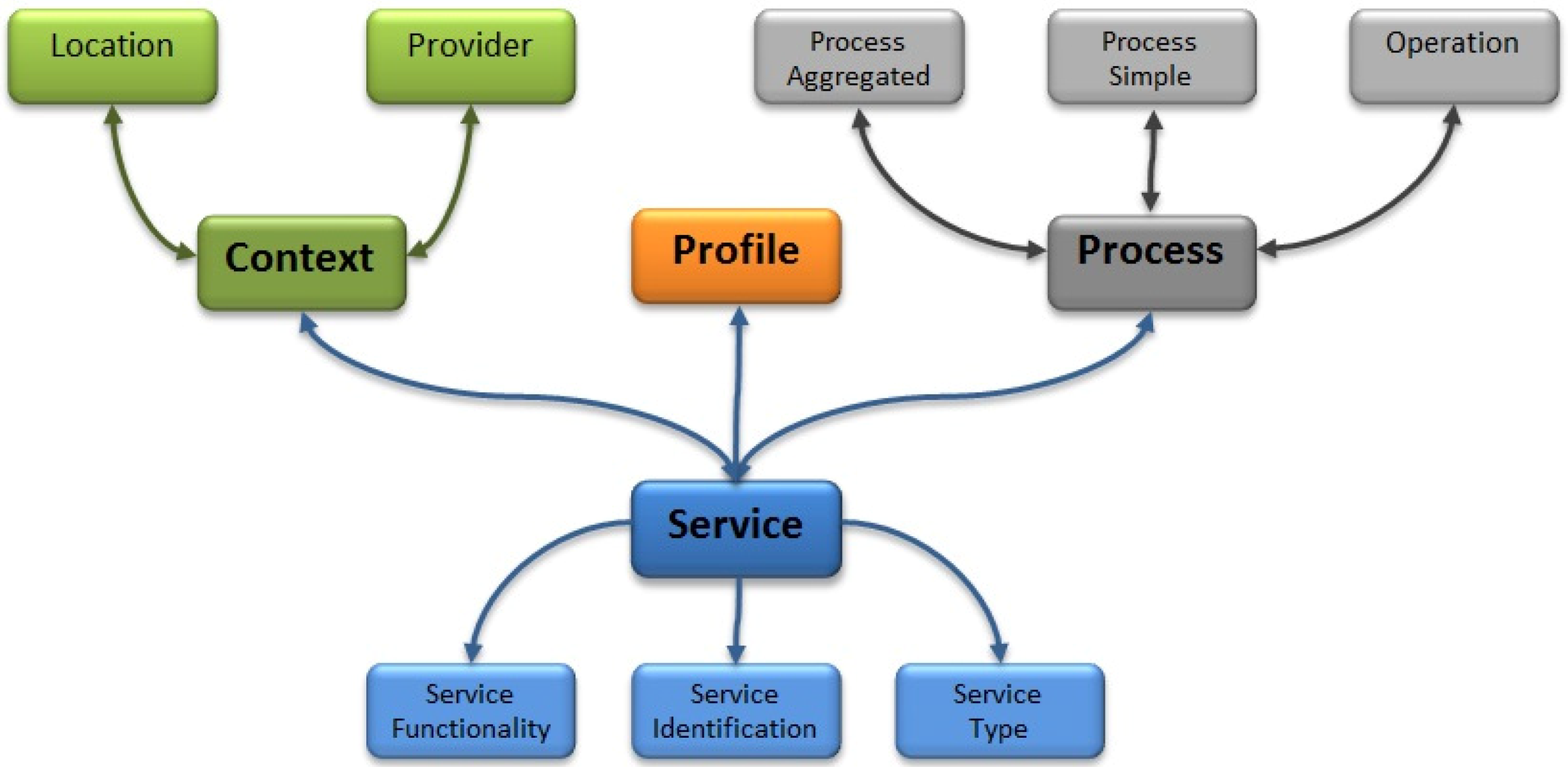
The service-oriented ontology has been designed in Web Ontology Language (OWL) with the Protégé tool [
40] and a general overview is presented in
Figure 10.
Figure 10.
General overview of the service-oriented ontology.
Figure 10.
General overview of the service-oriented ontology.
The main class—called “Service”—has, in turn, three subclasses: “ServiceFunctionality”, “ServiceIdentification” and “ServiceType”. The first one describes the functionality that the service has been designed for. The second subclass identifies uniquely the service inside the middleware architecture, and the third one indicates which sort of service is taking into account the architecture classification (high level services, device services, core services, common services, and low level services). There are three more important classes in the ontology directly related to the “Service” class. The first one is called “Context” which defines the interrelated conditions in which the service exists or occurs. It is able to provide the specific location (class “Location”) and inform about the provider of the service using the class “Provider”. The second one is the “Process” class. It represents the logic of the service which it can be a simple process (class “ProcessSimple”) or an aggregated one (class “ProcessAggregated”). On the one hand, a simple process is a single service that takes the requested information directly and its functionality with the appropriated treatment provides. On the other hand, an aggregated process supplies a new functionality composed by two or more simple process. “Process” class is linked with “Operation” class because one process may have one or more operations associated. Finally, the class named as “Profile” represents the public description of the service; for example, the protocol used between the service and the application that are using it.
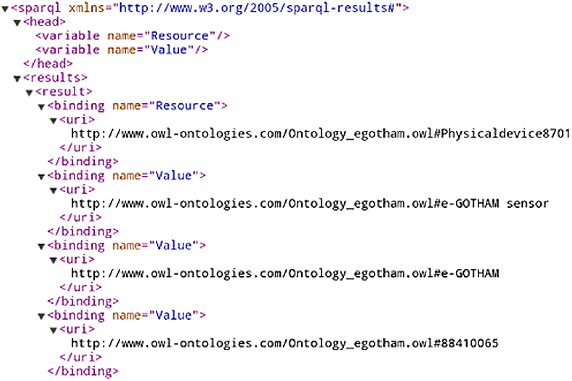
Figure 11 shows an example of a semantically annotated service represented in RDF; it shows a plethora of semantically annotated information: functionality, type, identification or location are provided, as well as the methods used to achieve the functionality (getHeatMeasurement).
This service-oriented ontology has been managed by means of a Jena API [
24] that allows us to control all its classes and relationships using Java language. It offers the possibility of storing all the information in a semantic repository based on RDF triples, thus keeping it available to later consult these data with a particular query language called SPARQL [
41].
Figure 11.
Example of semantically annotated service.
Figure 11.
Example of semantically annotated service.
4.4. Device Registry
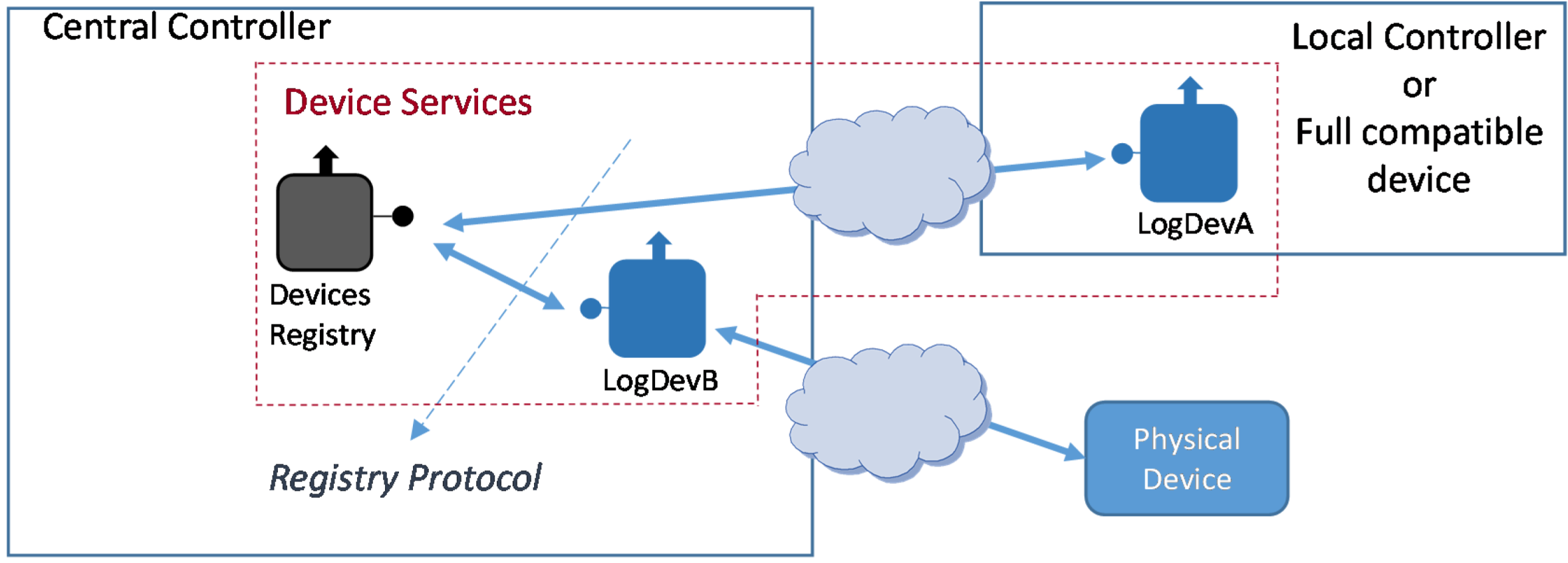
One of the most important tasks a semantic middleware must implement is service registration, so that existing services and their capabilities are known. Thus, Logical Devices require to be registered in the middleware to know their presence and their functionality. Logical Devices can be implemented inside the middleware architecture in two ways: Logical Device Type A and Logical Device Type B.
Figure 12 represents the scenario where the two types of existing Logical Devices are depicted:
Logical Device Type A. It will be implemented as part of the Local Controller. Since the Local Controller will be effectively a device accessible enough to install the Logical Device, it can be regarded as a full middleware-compliant device (e.g., LogDevA in
Figure 12);
Logical Device Type B. Unlike type A, this Logical Device is implemented outside the device it is bound to; in fact, it will be usually implemented at the Central Controller (e.g., LogDevB in
Figure 12). This option will be used, for example, when the physical device is not computationally capable of having a functional middleware installation.
Figure 12.
Logical device types.
Figure 12.
Logical device types.
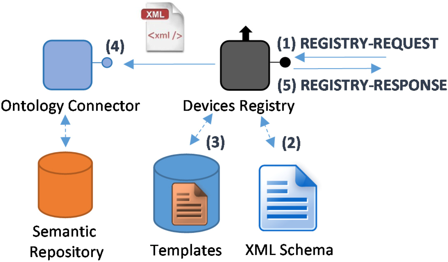
4.4.1. Registry Protocol
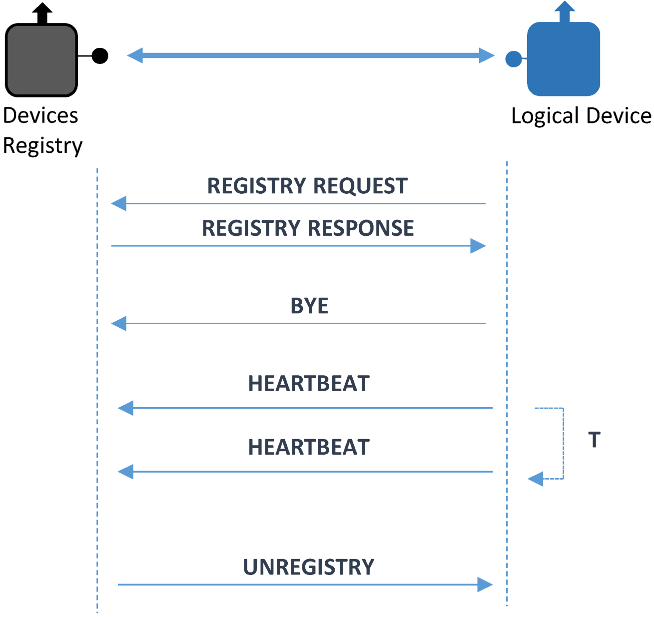
It is mandatory to elaborate a protocol to register the Logical Devices that are mapping physical devices existing throughout the system. The two displayed kinds of Logical Devices will use this protocol in their relations with the Device Registry, as illustrated in
Figure 13.
Figure 13.
Device registry protocol.
Figure 13.
Device registry protocol.
The protocol messages have been defined in the following manner:
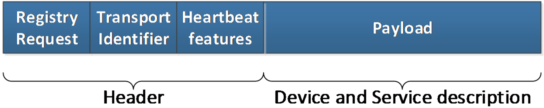
Registry Request. It is the message used to integrate a Logical Device. In this message there will be data required to send the request. These data are:
- a)
Message type: it has the same functionality as before: identifying the kind of message that is being transferred;
- b)
Transport identifier: used to particularize a device according to lower layer parameters, such as an IP address. It has been conceived as an optional parameter, as it is used just in case lower layers do not provide a way to get a sender identifier;
- c)
Heartbeat features: used so as to confirm that once the registration has taken place, the devices that have been registered will send messages to guarantee that they remain functional and can perform their assigned tasks. As related in [
42], using a dynamic procedure to send these messages that is aware of the success or failure of the device performance is advisable. Consequently, heartbeat messages will be given the opportunity to be sent at a decreasing rate, as long as all the previous ones have reached its destination successfully. Different algorithms can be used as well; if the value field has zero as a value, a constant periodic amount of time will be used between messages, otherwise some other ways of transmitting heartbeat messages can be used;
- d)
Payload: among the contents of this field there will be a physical device unique identifier (labeled as deviceTypeID in the XML representation of this message) and context sensitive data. By means of deviceTypeID information—which is providing the device manufacturer, model and serial number—one template will be used to complete the semantic registration of the device, as it will be described in
section 4.4.3. This template will be filled up with information from the Logical Device and sent to the Ontology Connector so as to have the device semantically stored.
The appearance of this message will be as represented in
Figure 14.
Figure 14.
Registry request message.
Figure 14.
Registry request message.
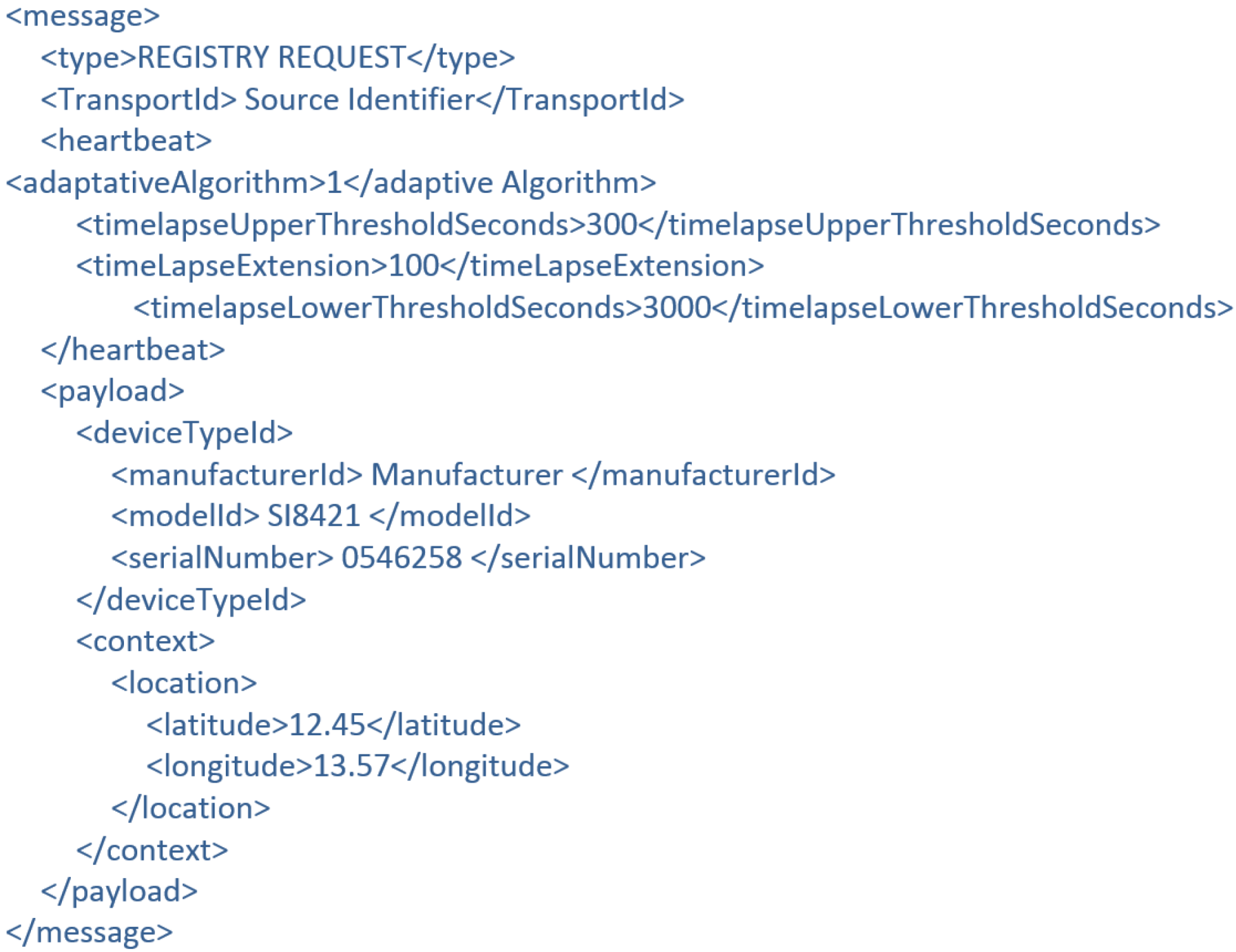
Additionally, the XML representation of the message resembles the ones that were depicted in
Figure 15. As it can be noted, heartbeat characteristics have been added as well.
Figure 15.
Device registry request XML example.
Figure 15.
Device registry request XML example.
Registry Response. Used to confirm that the registration process was completed. It is sent from the Device Registry to the Logical Device that sent a Registry request before;
Bye. This is a message sent when a Logical Device chooses voluntarily to be disconnected from the system (instead of being forced out by an accident or any other malfunctioning issues);
Unregister. This message is quite similar to Bye with a difference in the direction it is transferred: instead of travelling from the Logical Device to the Device Registry, it will go the other way round, as the action of disconnecting the device from the system will be taken by the Device Registry;
Heartbeat. This message will be the one that is used by the Logical Device to send a periodical acknowledgment of the good performance of the system.
4.4.2. Registering Physical Devices
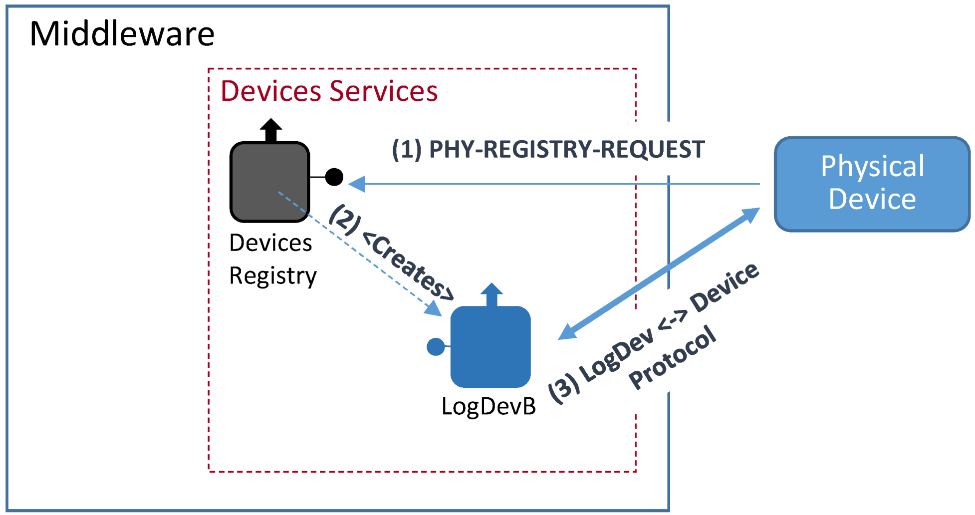
As far as logical device creation is concerned there are different procedures to launch Logical Devices, provided that their wanted type of Logical Device (A or B) is taken into account. Logical Devices categorized as type A either run in a Local Controller or are a Local Controller by themselves. In any case, they will be pre-installed Logical Device pre-existing the registration process. Type B Logical Devices must be generated by the Device Registry according to the process described in next lines.
Figure 16 shows the steps used to create a Logical Device of type B.
Figure 16.
Logical Device B type creation.
Figure 16.
Logical Device B type creation.
This process can be explained as follows:
The physical device sends a Phy-Registry-Request message to the Devices Registry. This message contains the same physical device unique identifier associated to the label <deviceTypeId> used in the previously described Registry Request message;
The Devices Registry service checks if the physical device is correctly formatted and creates, if checking was successful, the right bound Logical Device;
Once the logical device is created, it connects with its bound physical device using the appropriate communication protocol that will depend on the physical devices communication capabilities. The Logical Device will get from the physical device all the information needed to represent it within the middleware architecture.
4.4.3. Registry and Ontology
Up until this point, the procedures and actions related with the registry protocol carried out to register a Logical Device have already been described. However, the semantic registration in the middleware architecture must be explained too, as illustrated in
Figure 17.
Figure 17.
Semantic registry process.
Figure 17.
Semantic registry process.
The steps that must be taken for the complete process of a Type A registration device are:
A Request Registry for service registration will be received at the Device Registry;
This message will have data on its payload part that will have to be validated as any other XML-formatted document. In order to do so, there will be several XMLSchemas that effectively guarantee that the information received by the Device Registry is compliant with the format that is expected from the Logical Devices;
Semantic registration requires a template to be filled with the information once the content of the request has been validated. These templates will be pre-installed in the Central Controller with the deployed middleware architecture;
When the template fulfilling is finished, it is sent towards the Ontology Connector using the OSGi-based interface for internal middleware communications;
The Ontology Connector will collect the information sent by the Device Registry and store it for its future usage. The process has been depicted in
Figure 18.
Figure 18.
Ontology Connector components.
Figure 18.
Ontology Connector components.
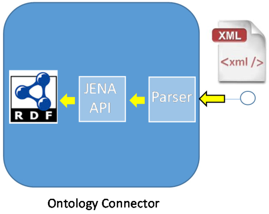
The role taken by the Ontology Connector will require the usage of three different inner components:
Parsing block: when it receives the XML-formatted information it will extract the most relevant fields to have them processed by the next block;
JENA API block: it is in charge of turning the attributes that had been collected before into RDF-formatted files that will contain the semantic information;
RDF files: they will contain the information related with the middleware ontology. It will usually be dealing with information about the services and their capabilities.
4.5. Middleware Service Registry
Middleware service registry is conceived as the registration of the services that take part in the middleware architecture rather than the devices that connect to the system. Since they are services that do not depend on physical devices, fewer messages are required for the whole process. Specifically, only registry request and registry response are required.
Registry Request. It is the message used to start the registration. It has two familiar fields:
- a)
Message type: it will identify what kind of message is being sent;
- b)
Payload: this field is containing the majority of the information required by the service. They will too make use of templates in order to determine how the content should look like in order to successfully complete the registration process.
Registry Response. This message will be sent back to the service that sent the registry request in the first place. The data that is part of the message are:
- a)
Message type: it defines the kind of message that is sent from one bundle to another;
- b)
Payload: it contains the information related with the result of the registry process.
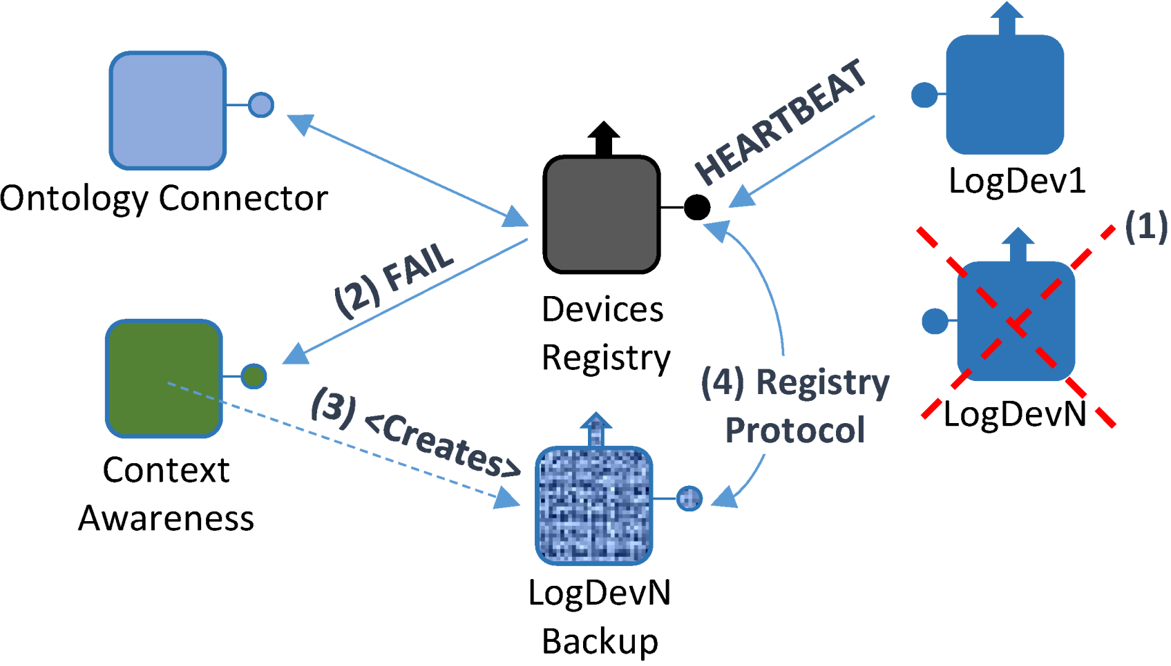
4.6. Context Awareness
The main concept behind our vision of context awareness is that the system must be able to carry on performing their duties in the best possible way, even if there are malfunctions affecting the system. Therefore, the idea of offering functionalities that guarantee
resilience has to be included. This scenario is the one that we consider as most important, since it is the one most likely to take place in an extended deployment of the scenario. Resilience is understood in the scope of this project as the ability of the system to carry on performing its functionalities while remaining unaffected to a great extent in case any issue comes up. Adding context aware features to a middleware architecture has been tried before; for example, Di Zheng
et al. [
43] put forward a context aware middleware architecture for Quality Management, albeit it is conceived primarily for mobile devices.
In order to manage all the operations related to context awareness, a specific component was developed for them (Context Awareness service). Heartbeat messages are important for resilience, as it will be acknowledging the presence of the devices taking part in the system and, by proxy, its regular performance as the procedure is represented in
Figure 19.
Figure 19.
Logical device backing up scenario.
Figure 19.
Logical device backing up scenario.
The Logical Device backing up process can be explained as follows:
A failure takes place in one of the devices integrated in the system; consequently, it affects the Logical Device that is bound to it (Logical Device N). Therefore, it will not be able to send any Heartbeat messages to the Device Registry;
In the absence of Heartbeat messages, Logical Device N will be forced to send a FAIL message, containing the Logical Device N unique identifier, along with the last time when a successful heartbeat message was received;
By using the unique identifier, a Logical Device backup will be created by the Context Awareness component, specifically created for this task according to all the functionalities that were previously contained by the Logical Device, thus creating Logical Device N Backup (LogDevN Backup);
At this point, a lighter registry request message will be sent by LogDevN Backup to complete the registration process.
After having the former Logical Device replaced by its new LogDevN Backup, the latter will be kept functional until there is a new registry request from the physical device that had previously gone out of order. In that case, the procedure that is used to acknowledge the recovery of the former Logical Device must be foreseen as well. It should be executed following next steps displayed in
Figure 20:
When the LogDevN gets recovered it will start running again. Since it will have to be notified for the whole middleware architecture, the registry protocol must be initiated;
LogDevN will be registered. At this very moment, LogDevN Backup will no longer be necessary; a Recover message will be sent from the Device Registry component to the Context Awareness one so as to notify the changes in the existing Logical Devices;
Also, this change is notified at the Ontology Connector. It will edit the ontology contents in order to update it to the new current situation;
Finally, the Logical Device that was used as a backup will be unregistered. For this purpose, a message to unregister the backup Logical Device.
Figure 20.
Logical Device resume.
Figure 20.
Logical Device resume.


