Article

Induced Voltages Ratio-Based Algorithm for Fault Detection, and Faulted Phase and Winding Identification of a Three-Winding Power Transformer

1
Wind Energy Grid-Adaptive Technology Research Center, Chonbuk National University, Chonju 561-756, Korea
2
The School of Electrical and Electronic Engineering, Yonsei University, Seoul 120-749, Korea
3
The School of Electrical and Electronic Engineering, The University of Manchester, Manchester M13 9PL, UK
4
Department of Electrical Engineering, Wind Energy Grid-Adaptive Technology Research Center, and Smart Grid Research Center, Chonbuk National University, Chonju 561-756, Korea
*
Author to whom correspondence should be addressed.
Energies 2014, 7(9), 6031-6049; https://doi.org/10.3390/en7096031
Submission received: 6 August 2014 / Revised: 5 September 2014 / Accepted: 9 September 2014 / Published: 12 September 2014

Abstract

:
This paper proposes an algorithm for fault detection, faulted phase and winding identification of a three-winding power transformer based on the induced voltages in the electrical power system. The ratio of the induced voltages of the primary-secondary, primary-tertiary and secondary-tertiary windings is the same as the corresponding turns ratio during normal operating conditions, magnetic inrush, and over-excitation. It differs from the turns ratio during an internal fault. For a single phase and a three-phase power transformer with wye-connected windings, the induced voltages of each pair of windings are estimated. For a three-phase power transformer with delta-connected windings, the induced voltage differences are estimated to use the line currents, because the delta winding currents are practically unavailable. Six detectors are suggested for fault detection. An additional three detectors and a rule for faulted phase and winding identification are presented as well. The proposed algorithm can not only detect an internal fault, but also identify the faulted phase and winding of a three-winding power transformer. The various test results with Electromagnetic Transients Program (EMTP)-generated data show that the proposed algorithm successfully discriminates internal faults from normal operating conditions including magnetic inrush and over-excitation. This paper concludes by implementing the algorithm into a prototype relay based on a digital signal processor.

1. Introduction

Power transformer protection relays in a power system must be able to differentiate internal faults from all other operating conditions, and current differential relays have been widely used for transformer protection. The relays, however, are prone to malfunctioning during magnetic inrush or over-excitation conditions because the magnetizing current becomes significant, but cannot be measured. To prevent malfunctions, the relays adopt restraining or blocking signals that are derived from the current, the voltage, or the flux [1].
Restraining or blocking signals for a three-winding transformer are determined in a very similar manner to those of a two-winding transformer, except for the number of the signals. A differential relay used the one vector difference as a restraint quantity and the vector sum as the differential operating quantity [2].
The transformer differential relays with harmonic based restraining or blocking signal [3,4,5,6] ensure stability during magnetizing inrush and over-excitation, but may reduce the sensitivity for internal faults. In addition, the method causes an operating time delay of a relay because of the restraining or blocking signal.
Transformer protection techniques that rely on the electro-magnetic differential equations of the transformer were suggested [7,8,9]. Since these techniques do not require additional restraining or blocking signals, the operating time of the relays is faster than that of the conventional differential relay with harmonic-based restraining or blocking signals. The delta winding currents, which are practically unavailable, were used in [7], whilst the line currents of the delta side were used in [8,9]. However, these techniques cannot be used directly for fault type classification.
Recently, modern numerical protection technologies for power transformers have been proposed using wavelet transforms [10,11], neural networks [12,13], Park’s components [14,15], and gradient vector of the differential current [16]. Wavelet-based algorithms were proven to achieve good accuracy [10,11]. However, it is crucial to choose the appropriate wavelet for satisfactory analysis and long data windows are required. Moreover, they are susceptible to noises and unpredicted disturbances. Neural networks [12,13] were proved as an efficient tool for classification and identification of the events. However, a huge computational burden is inevitable for training or comparing signals.
A restraining signal was obtained using Park’s transform [14,15], whilst the slope of the differential current in each phase was used for differential protection [16]. These techniques successfully differentiate magnetic inrush from internal faults, particularly in the case of simultaneous inrush and internal faults, but difficulties arise in identifying the faulted phase and winding.
Fault classification methods of a power transformer were proposed [17,18]. Pseudo-inversion of the linear relationship between faults and protection response, norm in the Banach space, and Bayes probability calculation are used [17]. The discrete wavelet transform in combination with back propagation neural networks was used to classify internal fault types of a three-phase transformer [18]. However, difficulties will arise in identifying the faulted phase and winding of a three-winding transformer with delta-connected windings.
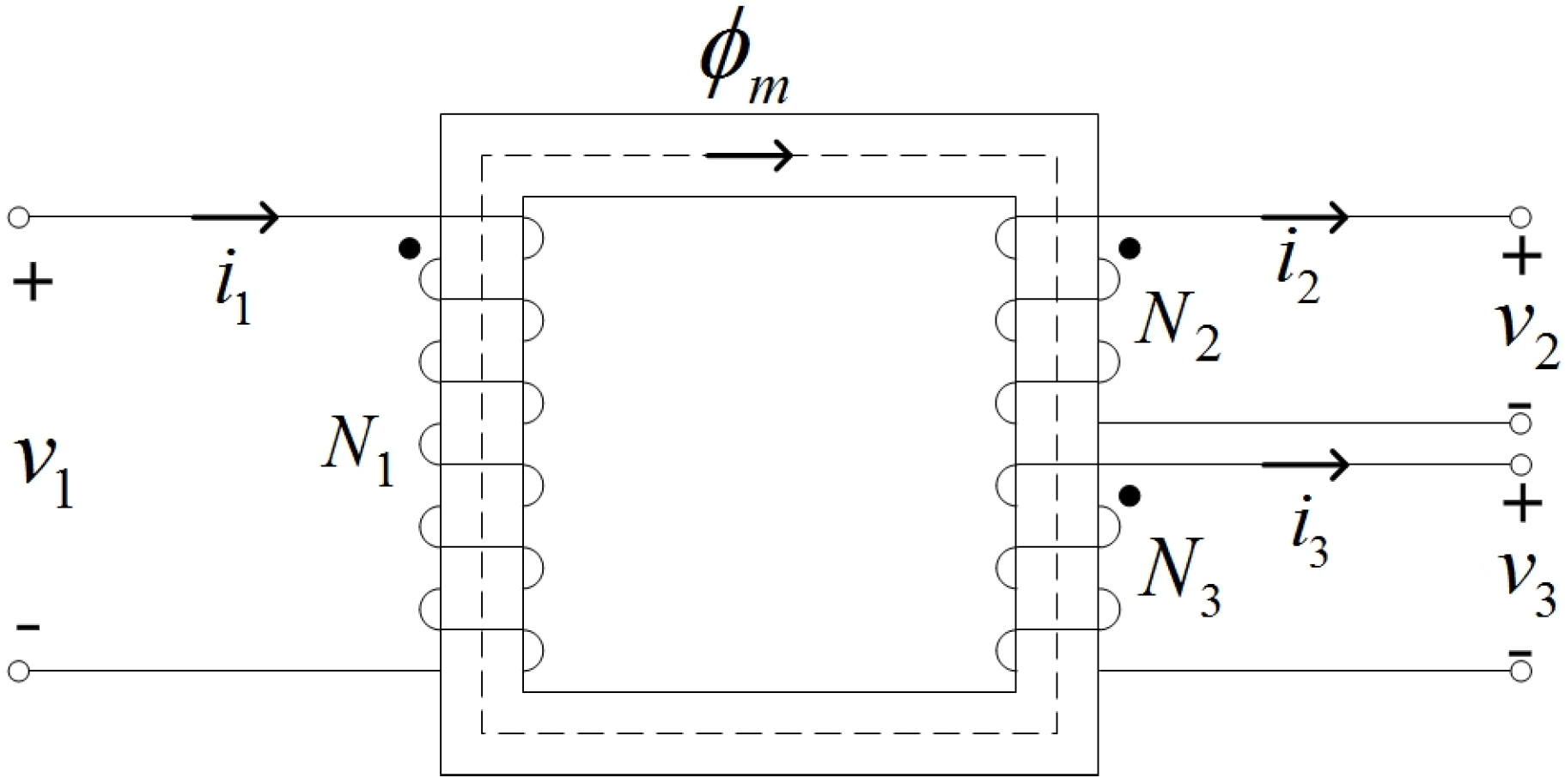
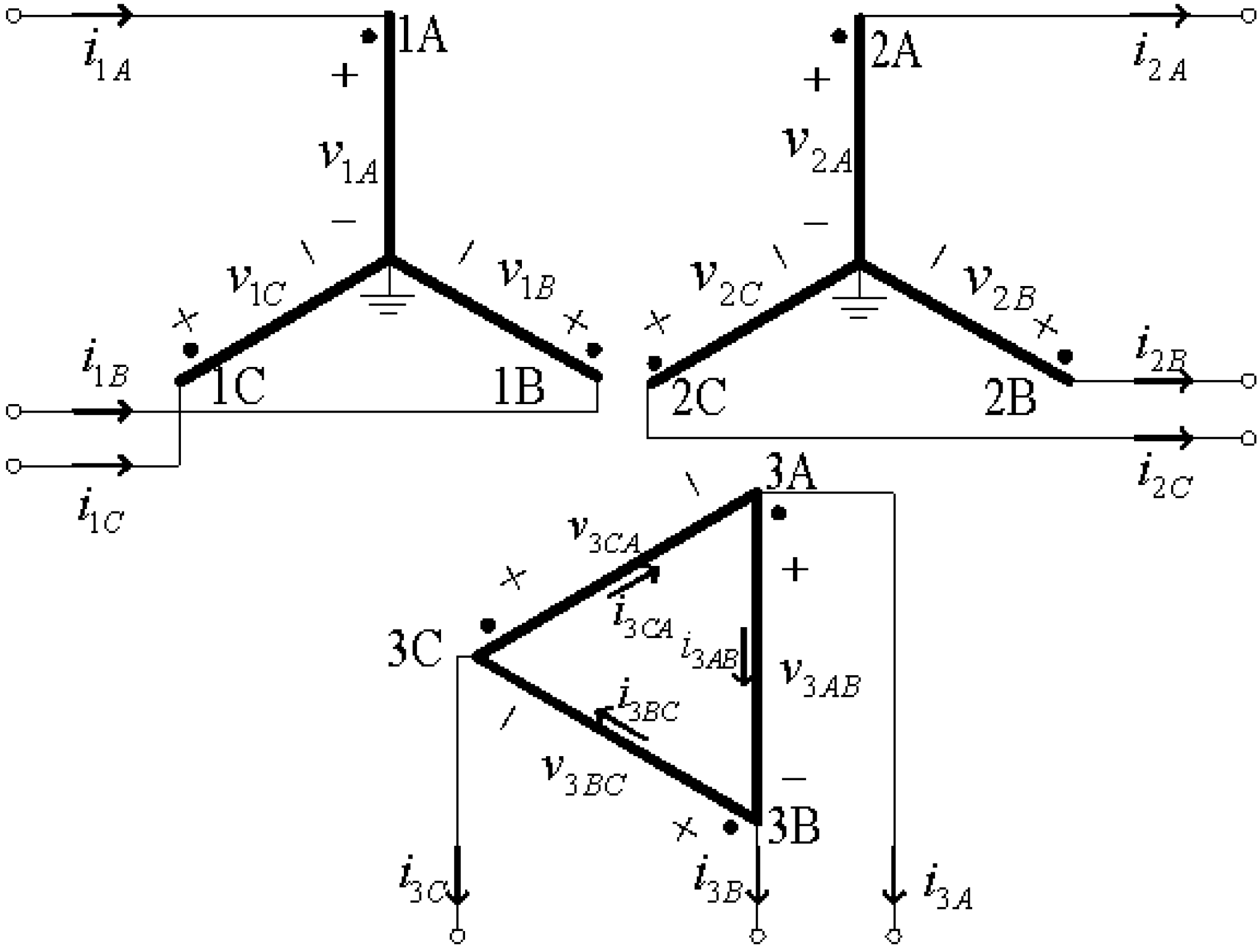
This paper proposes an algorithm for fault detection and faulted phase and winding identification of a three-winding power transformer based on the induced voltages in a power system. This paper extends the method in [
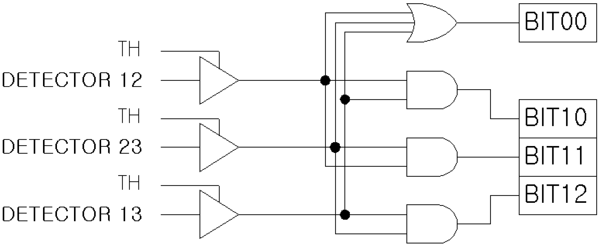
9] to a three-winding transformer and suggests a rule for fault detection and fault type identification. The ratio of the induced voltages of the primary-secondary, primary-tertiary and secondary-tertiary windings is the same as the corresponding turns ratio during normal operating conditions, magnetic inrush, and over-excitation. It differs from the turns ratio during an internal winding fault. For a single phase or a three-phase transformer with wye-connected windings, induced voltages of each pair of windings are estimated. On the other hand, for a three-phase transformer with delta-connected windings, the induced voltage differences are estimated to use the line currents, which are practically available. Nine detectors and a rule are suggested for fault detection for faulted phase and winding identification. The performance of the proposed algorithm was investigated with Electromagnetic Transients Program (EMTP)-generated data under various internal fault conditions and normal operating conditions including magnetic inrush and over-excitation. The paper concludes by implementing the algorithm in a prototype relay based on a digital signal processor.

2. Fault Detection, and Faulted Phase and Winding Identification of a Three-Winding Transformer Based on the Induced Voltages

In [8,9] the design and evaluation of a fault detection technique based on the induced voltages was described. The technique can be extended to faulted phase and winding identification as well as fault detection of a three-winding transformer. In this Section, we will describe nine detectors and a rule for fault detection, and faulted phase and winding identification of a single phase transformer and a three-phase Y-Y-Δ transformer.

2.1. Three-Winding Single-Phase Transformer

Figure 1 shows a three-winding single-phase transformer. If there is no internal fault, v1, v2, and v3 at any instant can be given by:
v 1 = R 1 i 1 + L l 1 d i 1 d t + e 1
v 2 = R 2 i 2 L l 2 d i 2 d t + e 2
v 3 = R 3 i 3 L l 3 d i 3 d t + e 3
Figure 1. Three-winding single-phase transformer.
Energies 07 06031 g001
The induced voltages e1, e2, and e3 can be determined using Equations (1)–(3). The ratios of the induced voltages (RIVs) between the matching windings are defined by:
RIV 12 = e 1 e 2 RIV 13 = e 1 e 3 RIV 23 = e 2 e 3
In the steady state, RIV12, RIV13 and RIV23 at any instant equal the turns ratios i.e., N1/N2, N1/N3, and N2/N3; the only exception is when e1 = 0, e2 = 0, or e3 = 0. For magnetic inrush and over-excitation, the three RIVs are also equal to their turns ratios, although e1, e2, and e3 are now non-sinusoidal and distorted. On the other hand, for internal faults, the RIV associated with the faulted winding is not equal to the turns ratio. This is why the three RIVs can be used directly for discriminating an internal fault from magnetic inrush and over-excitation. However, even for normal operating conditions, the RIVs are not always equal to the turns ratios because e1, e2, and e3 are instantaneous values and thus pass through zero. Therefore, the detectors described by Equations (5)–(7) are used to detect a fault instead of Equation (4). The detectors evaluate the percent difference between the two estimated induced voltages. If Equations (5)–(7) are less than a threshold, the transformer is not faulted; if one of them is greater, it is:
D e t e c t o r 12 = e 1 N 1 N 2 e 2 2 V 1 × 100 ( % )
D e t e c t o r 13 = e 1 N 1 N 3 e 3 2 V 1 × 100 ( % )
D e t e c t o r 23 = e 2 N 2 N 3 e 3 2 V 2 × 100 ( % )
In addition, the faulted winding can be identified using Detector12, Detector13 and Detector23 in accordance with a logic diagram shown in Figure 2. Table 1 shows a rule for detecting a fault and identifying a faulted winding from the detectors. A fault is detected when BIT00 is activated. This occurs if one or more detectors exceed a threshold. A primary winding fault is detected if BIT10 is active, and BIT11 and BIT12 are inactive. Similarly, a secondary and a tertiary winding fault can be detected.
Figure 2. Logic diagram for fault detection and faulted winding identification of a single-phase transformer.
Energies 07 06031 g002
Table 1. Rule for detecting a fault and the faulted winding for a three-winding single-phase transformer.
BIT00Fault detection
0No internal fault
1Internal fault
BIT10BIT11BIT12Faulted winding identification
100Primary winding
010Secondary winding
001Tertiary winding
111Two or three winding
Other casesUnidentified

2.2. Three-Winding Three-Phase Y-Y-Δ Transformer

A three-winding Y-Y-Δ transformer is studied in this paper. The connections of the primary, secondary and tertiary windings are shown in Figure 3. The voltages of the primary, secondary and tertiary windings can be represented by:
v 1 A = R 1 A i 1 A + L l 1 A d i 1 A d t + e 1 A
v 1 B = R 1 B i 1 B + L l 1 B d i 1 B d t + e 1 B
v 1 C = R 1 C i 1 C + L l 1 C d i 1 C d t + e 1 C
v 2 A = R 2 A i 2 A L l 2 A d i 2 A d t + e 2 A
v 2 B = R 2 B i 2 B L l 2 B d i 2 B d t + e 2 B
v 2 C = R 2 C i 2 C L l 2 C d i 2 C d t + e 2 C
v 3 A B = R 3 A B i 3 A B + L l 3 A B d i 3 A B d t + e 3 A B
v 3 B C = R 3 B C i 3 B C + L l 3 B C d i 3 B C d t + e 3 B C
v 3 C A = R 3 C A i 3 C A + L l 3 C A d i 3 C A d t + e 3 C A
Figure 3. Three-winding three-phase Y-Y-Δ transformer.
Energies 07 06031 g003
e1A, e1B, e1C, e2A, e2B and e2C can be obtained directly from Equations (8–13). Thus, the three detectors between the primary and secondary windings can be derived in a similar way to a single-phase transformer.
For the delta winding, e3AB, e3BC and e3CA cannot be derived from Equations (14–16) because i3AB, i3BC and i3CA are practically unavailable. The line currents are always available and consequently, i3A, i3B and i3C in Equation (17) are used to detect an internal fault.
i 3 C A i 3 A B = i 3 A i 3 A B i 3 B C = i 3 B i 3 B C i 3 C A = i 3 C
This assumes the following assumptions are also valid:
R 3 A B R 3 B C R 3 C A = R L l 3 A B L l 3 B C L l 3 C A = L l
Equation (14) is subtracted from Equation (16) to derive Equation (19), Equation (15) from Equation (14) to derive Equation (20), and Equation (16) from Equation (15) to derive Equation (21), i.e.,:
e 3 C A e 3 A B = v 3 C A v 3 A B R i 3 A L l d i 3 A d t
e 3 A B e 3 B C = v 3 A B v 3 B C R i 3 B L l d i 3 B d t
e 3 B C e 3 C A = v 3 B C v 3 C A R i 3 C L l d i 3 C d t
Whilst e3AB, e3BC and e3CA cannot be calculated, their differences can be calculated from Equations (19–21). Similarly, e1Ce1A, e1Ae1B, and e1Be1C, the corresponding equations to Equations (19), (20) and (21) can be derived from Equations (8–10):
e 1 C e 1 A = v 1 C v 1 A ( R 1 C i 1 C R 1 A i 1 A ) ( L l 1 C d i 1 C d t L l 1 A d i 1 A d t )
e 1 A e 1 B = v 1 A v 1 B ( R 1 A i 1 A R 1 B i 1 B ) ( L l 1 A d i 1 A d t L l 1 B d i 1 B d t )
e 1 B e 1 C = v 1 B v 1 C ( R 1 B i 1 B R 1 C i 1 C ) ( L l 1 B d i 1 B d t L l 1 C d i 1 C d t )
For a Y-Y-Δ transformer, if there is no internal fault, Equations (25) and (26) are valid:
e 1 A e 2 A = N 1 N 2 e 1 B e 2 B = N 1 N 2 e 1 C e 2 C = N 1 N 2
e 1 A e 3 A B = N 1 N 3 e 1 B e 3 B C = N 1 N 3 e 1 C e 3 C A = N 1 N 3
e1A, e1B, e1C, e2A, e2B and e2C can be calculated, but e3AB, e3BC and e3CA cannot. Thus, Equation (26) cannot be applied directly to the detectors. In this paper, Equation (27) is used for fault detection of a Y-Y-Δ transformer, because Equation (26) is a necessary and sufficient condition for Equation (27). Its proof was shown in [8].
e 1 C e 1 A e 3 C A e 3 A B = N 1 N 3 , e 1 A e 1 B e 3 A B e 3 B C = N 1 N 3 , e 1 B e 1 C e 3 B C e 3 C A = N 1 N 3
Thus, the six detectors can be expressed as:
D e t e c t o r 1 = e 1 A N 1 N 2 e 2 A 2 V 1 A × 100 ( % )
D e t e c t o r 2 = e 1 B N 1 N 2 e 2 B 2 V 1 B × 100 ( % )
D e t e c t o r 3 = e 1 C N 1 N 2 e 2 C 2 V 1 C × 100 ( % )
D e t e c t o r 4 = ( e 1 C e 1 A ) N 1 N 3 ( e 3 C A e 3 A B ) 2 V 1 C A × 100 ( % )
D e t e c t o r 5 = ( e 1 A e 1 B ) N 1 N 3 ( e 3 A B e 3 B C ) 2 V 1 A B × 100 ( % )
D e t e c t o r 6 = ( e 1 B e 1 C ) N 1 N 3 ( e 3 B C e 3 C A ) 2 V 1 B C × 100 ( % )
The Detectors 1–6 are sufficient only for fault detection. However, more detectors are needed for faulted winding identification. As in a single-phase transformer, the additional three detectors (Equations (34–36)) between the secondary and tertiary windings can be used to identify the faulted winding:
D e t e c t o r 7 = ( e 2 C e 2 A ) N 2 N 3 ( e 3 C A e 3 A B ) 2 V 2 C A × 100 ( % )
D e t e c t o r 8 = ( e 2 A e 2 B ) N 2 N 3 ( e 3 A B e 3 B C ) 2 V 2 A B × 100 ( % )
D e t e c t o r 9 = ( e 2 B e 2 C ) N 2 N 3 ( e 3 B C e 3 C A ) 2 V 2 B C × 100 ( % )
Table 2 and Figure 4 show a logic diagram and a rule for detecting a fault and identifying the faulted phase and winding from the detectors (Equations (28)–(36)). BIT00 is used for detecting a fault. BIT10, BIT11 and BIT12 are used for identifying the faulted phase of the primary or secondary winding, whilst BIT20, BIT21 and BIT22 for identifying the faulted phase of the primary or tertiary windings. In addition, BIT30, BIT 31 and BIT32 are used for identifying the faulted winding. For example, if a fault occurs on the phase “A” of the primary winding, Detector 1, 4, and 5 exceed the threshold value. Then, BIT00 has 1 and thus a fault is detected. BIT10, BIT11 and BIT12 have 1, 0, and 0 whereas BIT20, BIT21 and BIT22 indicate 1, 1 and 0. Thus, the faulted phase is identified as an “A” phase. On the other hand, BIT30, BIT31 and BIT32 indicate 1, 0 and 0 and thus the faulted winding is identified as the primary winding.
Figure 4. Logic diagram for fault detection and faulted winding identification of a Y-Y-Δ transformer.
Energies 07 06031 g004
Table 2. Rule for detecting a fault and the faulted phase and winding for a three-winding three-phase transformer.
BIT 00Fault detection
0No internal fault
1Internal fault
BIT10BIT11BIT12Faulted phase identification
000No phase
100A phase
010B phase
001C phase
110A phase and B phase
011B phase and C phase
101C phase and A phase
111All phases
BIT20BIT21BIT22Faulted phase identification
000No phase
110A phase
011B phase
101C phase
111Two or three phases
Other casesUnidentified
BIT30BIT31BIT32Faulted winding identification
100Primary winding
010Secondary winding
001Tertiary winding
111Two or three windings
Other casesUnidentified

3. Case Studies

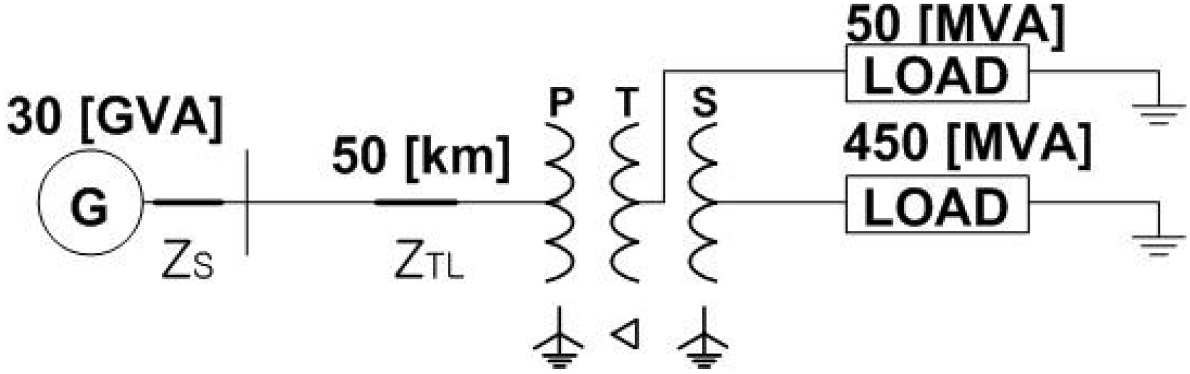
Figure 5 shows a single line diagram of the simulated system. The three-winding Y-Y-Δ transformer (345kV/154kV/23kV, 500 MVA) is modeled using EMTP and the sampling rate is 32 samples/cycle. The modeling techniques described in [19] are used to represent turn-to-ground and turn-to-turn winding faults.
The hysteresis characteristics of the core are modeled using a type-96 element; the saturation point of (100 A, 822 Vs) is selected using HYSDAT, a subroutine of EMTP. Butterworth 2nd order filters with a stop-band cut-off frequency of 960 Hz (sampling frequency/2) are used as anti-aliasing filters.
Figure 5. Single line diagram of the simulated system.
Energies 07 06031 g005
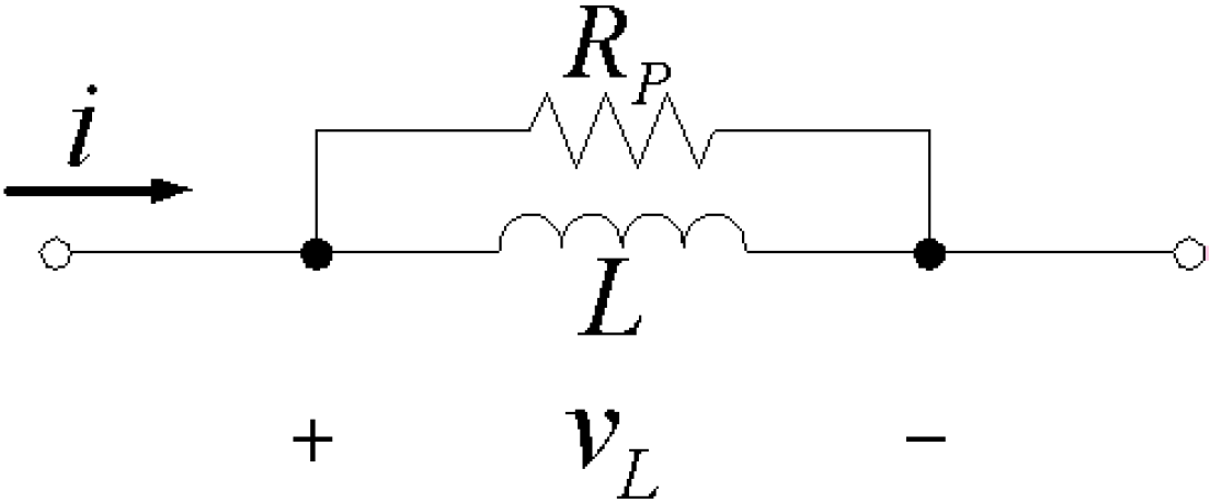
Equations (8–13) and (19–24) contain derivative terms, which can be approximated numerically. Among the approximation methods using two successive sample points, the trapezoidal rule causes errors smaller than the backward Euler method. However, it causes numerical oscillation. In this paper, the differentiation terms are approximated by the trapezoidal rule, expressed in the form of Equation (37). Numerical oscillations are damped by the use of a parallel damping resistance, RP, as shown in Figure 6 [20]:
v L ( t ) = 1 Δ t 2 L + 1 R P { i ( t ) i ( t Δ t ) } R P 2 L Δ t R P + 2 L Δ t v ( t Δ t )
RP is calculated using Equation (38), as suggested by Alvarado [20]:
R P = 20 3 2 L Δ t
Figure 6. Inductance model for the parallel damping.
Energies 07 06031 g006
The performance of the proposed algorithm is verified under various operating conditions such as magnetic inrush, internal winding faults, over-excitation and different core characteristics. For convenience, six Detectors for detecting an internal fault are shown in the case studies.

3.1. Magnetic Inrush

The magnitude of the inrush current depends on the energisation angle, the remanent flux in the core, and the load current. Thus, inrush data is generated by varying the above three parameters in accordance with Table 3.
Table 3. Conditions of magnetic inrush data Generation.
Energisation angle (°)0, 90
Remanent flux (%)0, 30, 50, 80
LoadNo load, full load
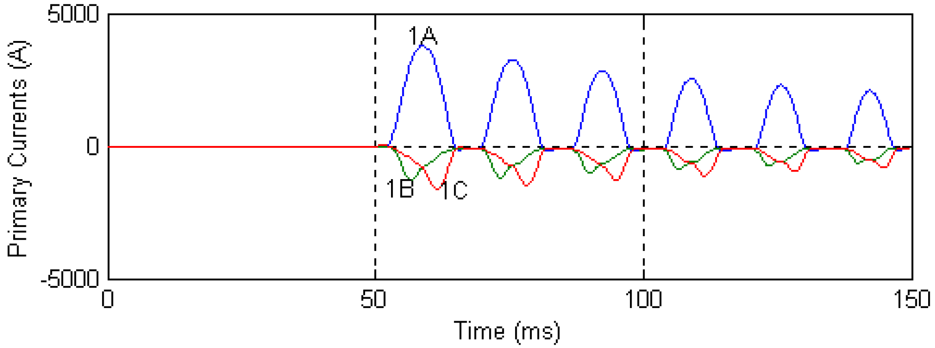
Case 1: Energisation angle of 0°, 80% remanent flux, no load;
Figure 7, Figure 8, Figure 9 and 
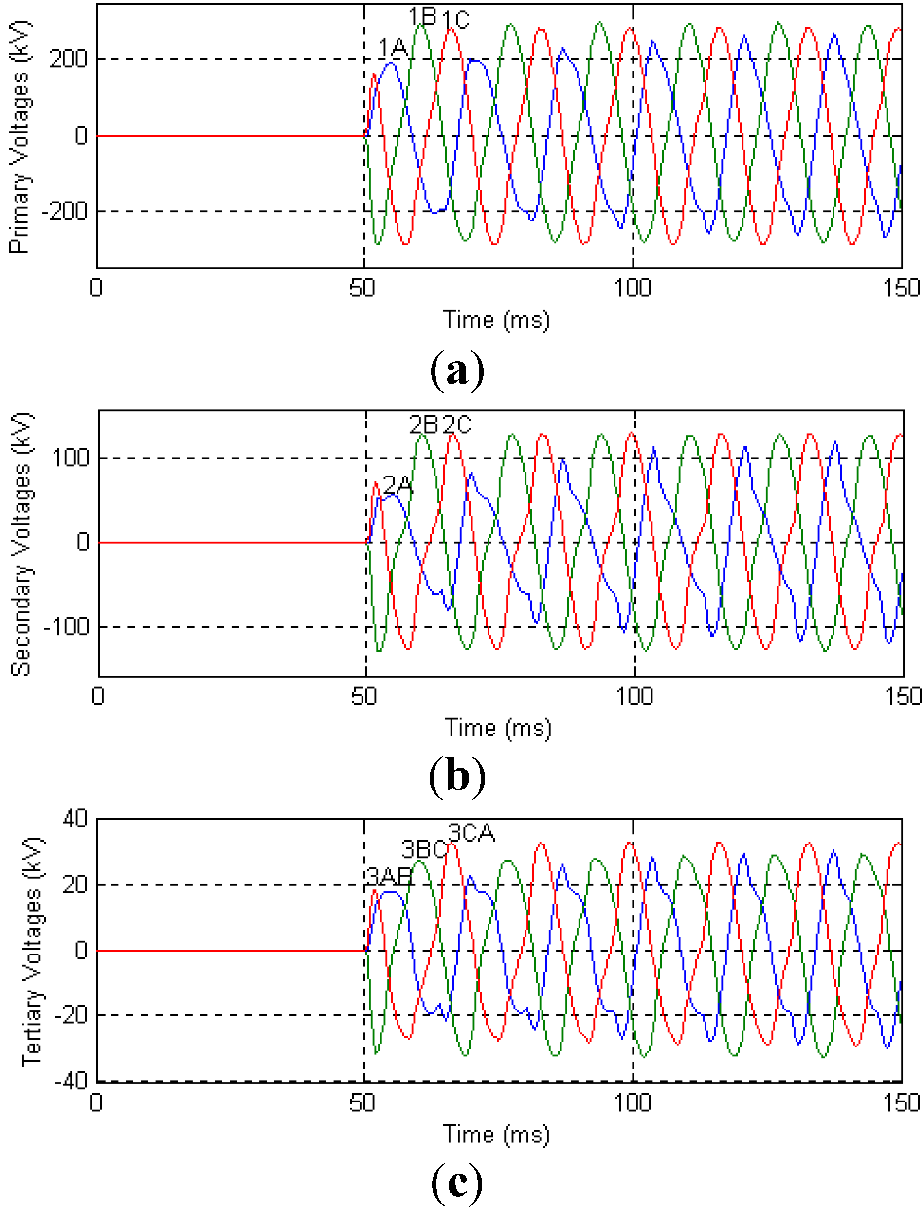
Figure 10 show the results for Case 1. An energisation angle of 0° and 80% remanent flux results in very large inrush currents in the primary windings. The three-phase voltages are severely distorted as shown in Figure 8. Using the currents and voltages, induced voltages or induced voltage differences are estimated.
Figure 7. Three-phase primary currents for Case 1.
Energies 07 06031 g007
Figure 8. Three-phase voltages for Case 1 (a) Primary voltages (v1A, v1B, v1C); (b) Secondary voltages (v2A, v2B, v2C); and (c) Tertiary voltages (v3AB, v3BC, v3CA).
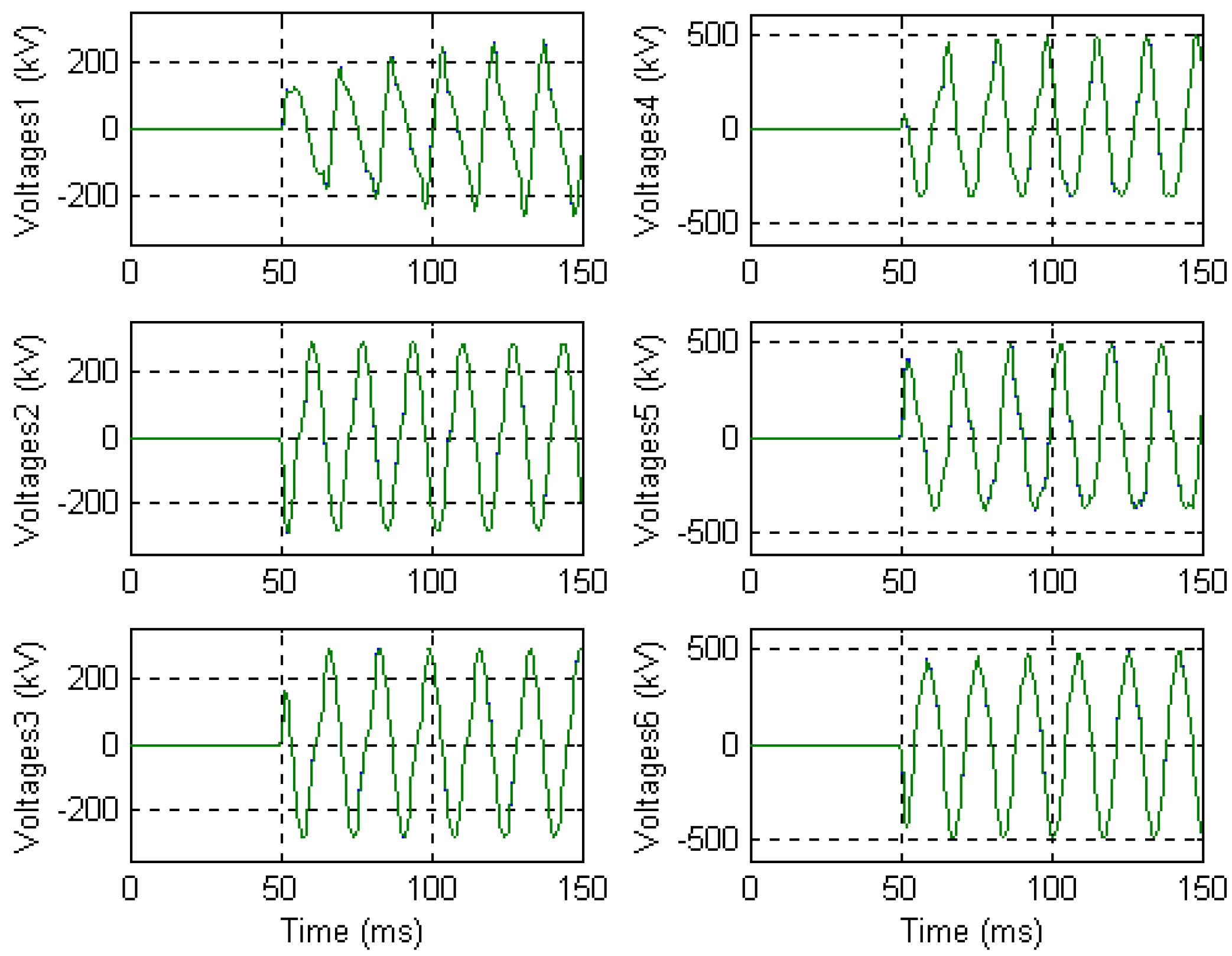
Energies 07 06031 g008
Figure 9. Two induced voltages of Voltage 1‒3 and two induced voltage differences of Voltage 4‒6 for Case 1.
Energies 07 06031 g009
Figure 10. Detectors and the trip signals for Case 1.
Energies 07 06031 g010
Two estimated induced voltages of Voltages 1‒3 and two estimated induced voltage differences of Voltages 4‒6, which are terms in the numerator of the six detectors, are shown in six subfigures in Figure 9. For example, Voltages 4 shows e1Ce1A and N1/N3(e3CAe3AB) of Detector 4, estimated from Equations (22) and (19), respectively. As expected, they are non-sinusoidal and severely distorted. The results clearly indicate that the two estimated terms are nearly the same even though the inrush currents are very large and the voltages are severely distorted.
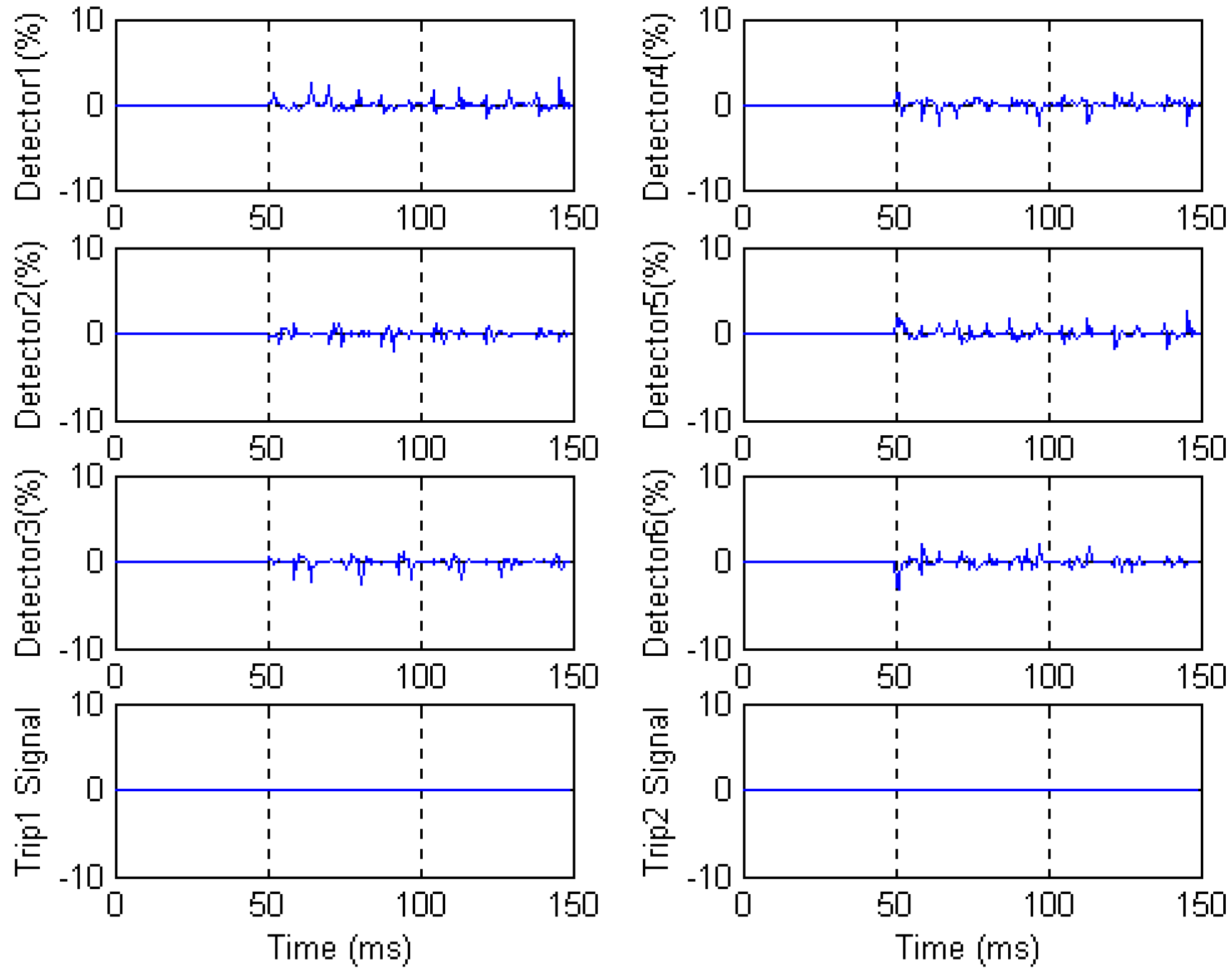
The operating threshold for the detectors is determined by considering the noise caused by the hardware, the sensitivity of a relay, stability margin of the relay and so on. For the system studied in this paper, the recommended value is 5%. In addition, a security counter is used to prevent mal-function due to transients. If a sample value in the detector exceeds 5%, the counter is increased by 1; if not, it is decreased by 1. In addition, if the counter is less than 0, it is reset to 0. If the counter exceeds 4, the trip signal is activated. Figure 10 shows the operating response of the six detectors and the two trip signals. The Trip1 and Trip2 signals are issued based on the results of Detectors 1–3 and Detectors 4–6, respectively. As all six remain below 5%, none of the trip signals are activated.

3.2. Internal Winding Faults

The fault data for various faults on the phase ‘A’ of the primary winding were generated and used to test the algorithm. The test results for the two of the fault scenarios are described in Cases 2 and 3:
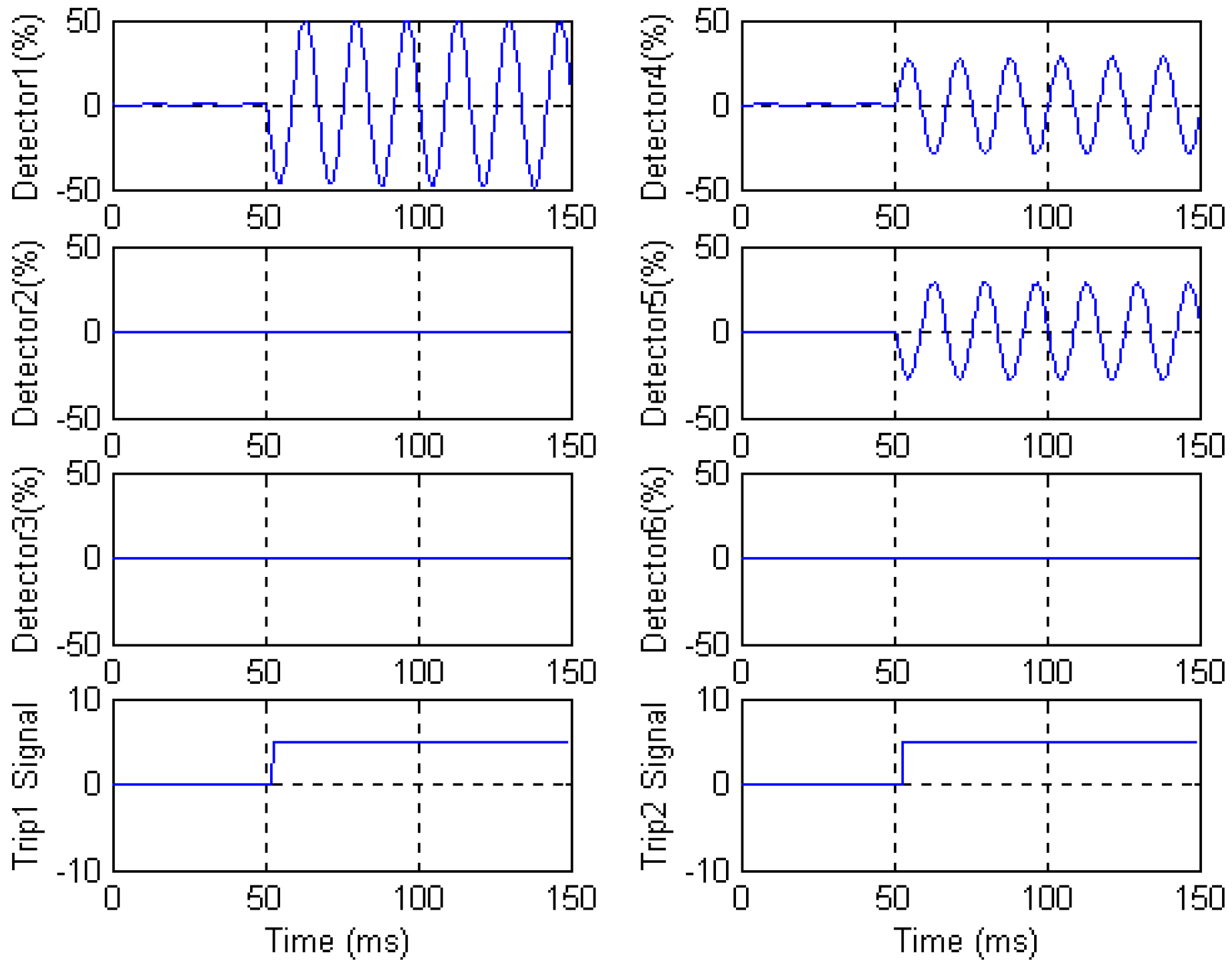
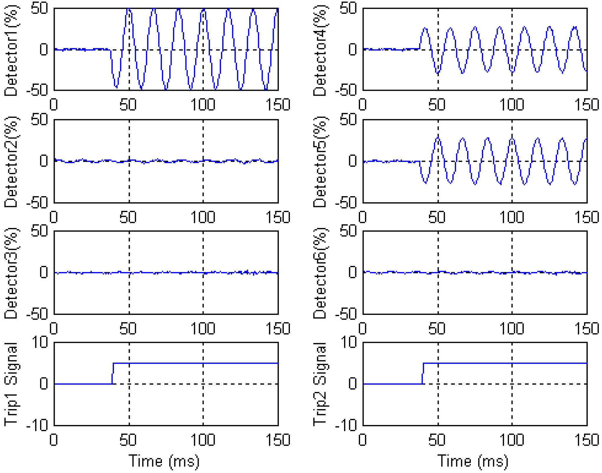
Case 2: A turn-to-ground fault, located 60% from the neutral winding end and at 0° inception angle;
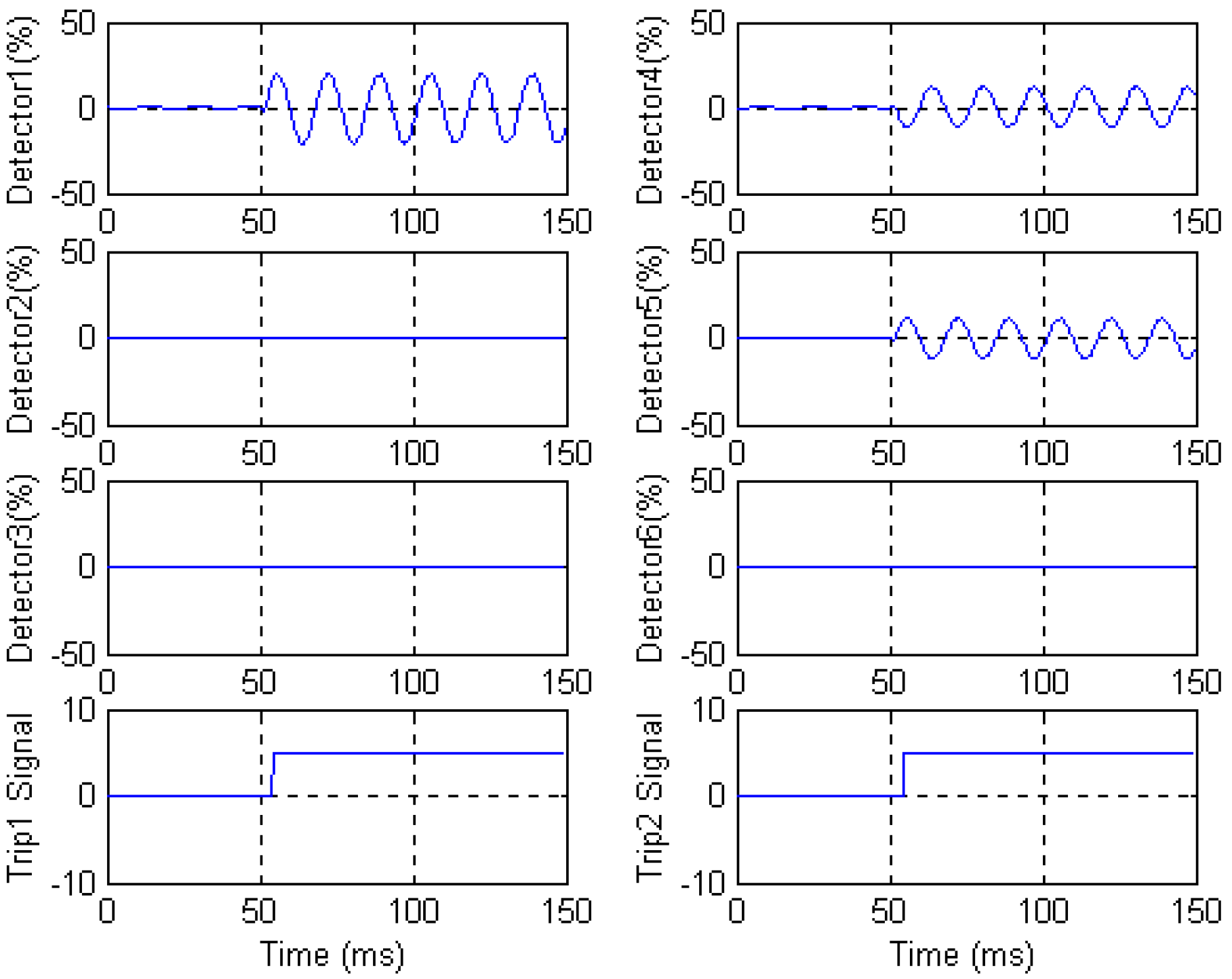
Case 3: A turn-to-turn fault, located between 20% and 10% and at 0° inception angle;
Figure 11 and Figure 12 show the operating responses of the six detectors for Cases 2 and 3, respectively. As expected, the two induced voltage differences are not the same and thus Detectors 1, 4 and 5 exceed the 5% operating threshold. The signals in Detectors 2, 3 and 6 remain small, because they are not affected by a fault on phase A. In Case 2, the Trip1 and Trip2 signals are activated 2.6 and 3.1 ms, respectively, after fault occurrence. In Case 3, these delays are increased to 4.2 and 4.7 ms.
Figure 11. Detectors and the trip signals for Case 2.
Energies 07 06031 g011
Figure 12. Detectors and the trip signals for Case 3.
Energies 07 06031 g012

3.3. Over-Excitation

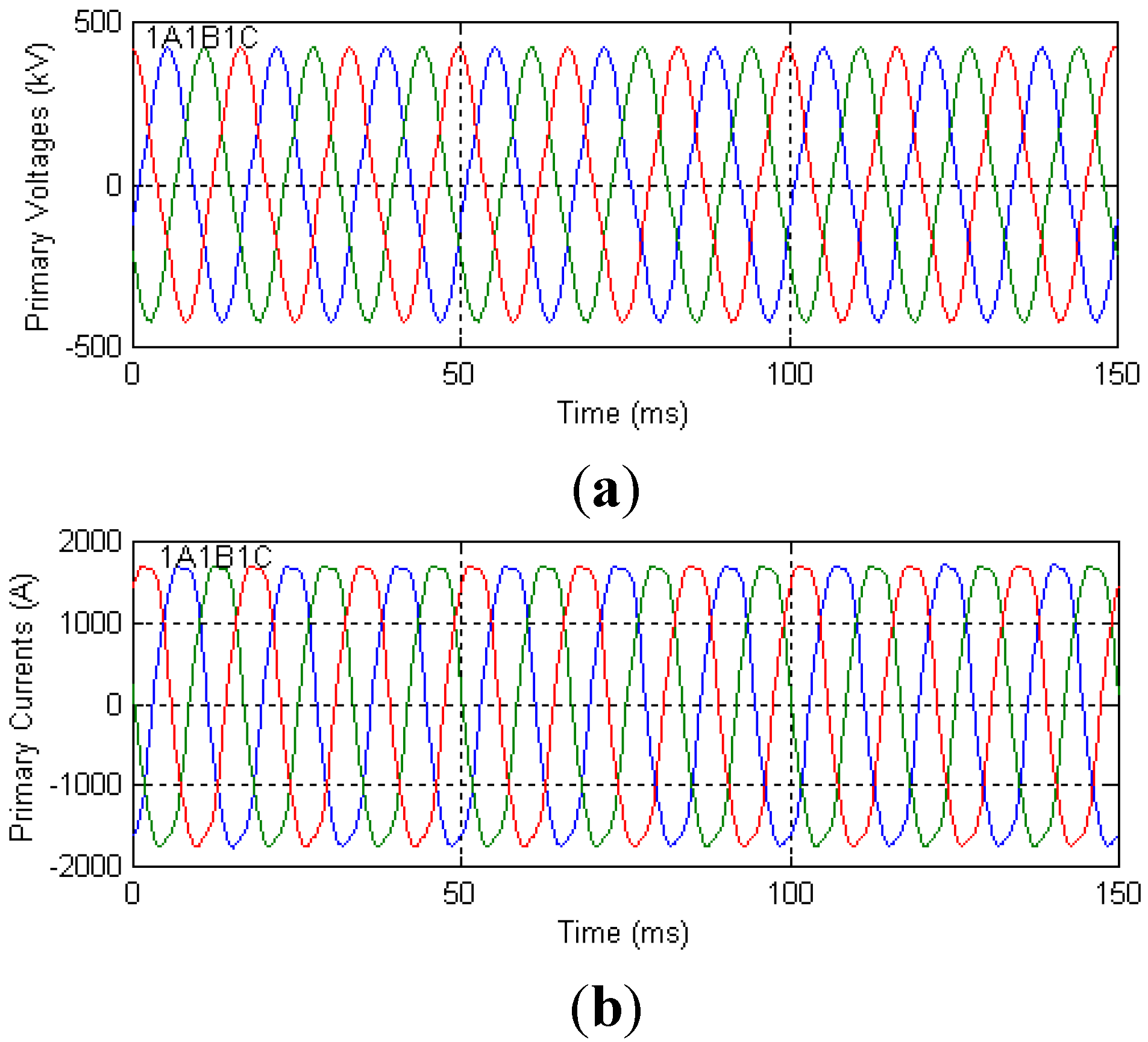
Case 4: Overvoltage of 150% applied, full load;
The algorithm was tested during over-excitation of the transformer. Figure 13 and Figure 14 show the results for an extreme over-voltage of 150% of the primary rated voltage and a full load condition. The primary currents and voltages are distorted as shown in Figure 13. However, the algorithm accurately estimates the induced voltage differences and thus the six Detectors remain below the operating threshold and the trip signals are not issued, as shown in Figure 14.
Figure 13. Primary voltages and current for Case 4 (a) Primary voltages (v1A, v1B, v1C); and (b) Primary currents (i1A, i1B, i1C).
Energies 07 06031 g013
Figure 14. Detectors and the trip signals for Case 4.
Energies 07 06031 g014

3.4. Different Core Characteristics

As the algorithm does not require hysteresis data, it can detect internal faults even if the core characteristics are changed. To validate this statement, tests were performed with different core characteristics; i.e., the excitation currents at the saturation points were changed without modifying the flux linkages. The winding resistances and the leakage inductances remain unchanged.
Case 5: Energisation angle of 0°, 80% remanent flux, no load, saturation point of (200 A, 822 Vs);
Figure 15 shows the results for Case 5; this is identical to Case 1 except for the change in the saturation point. The inrush currents are larger than those observed in Case 1 and the voltages are more severely distorted. However, the signals in the detectors remain below the 5% threshold; and the two trip signals are not activated. The results clearly show that the algorithm accurately estimates the induced voltage differences and is not affected by changing the core characteristics.

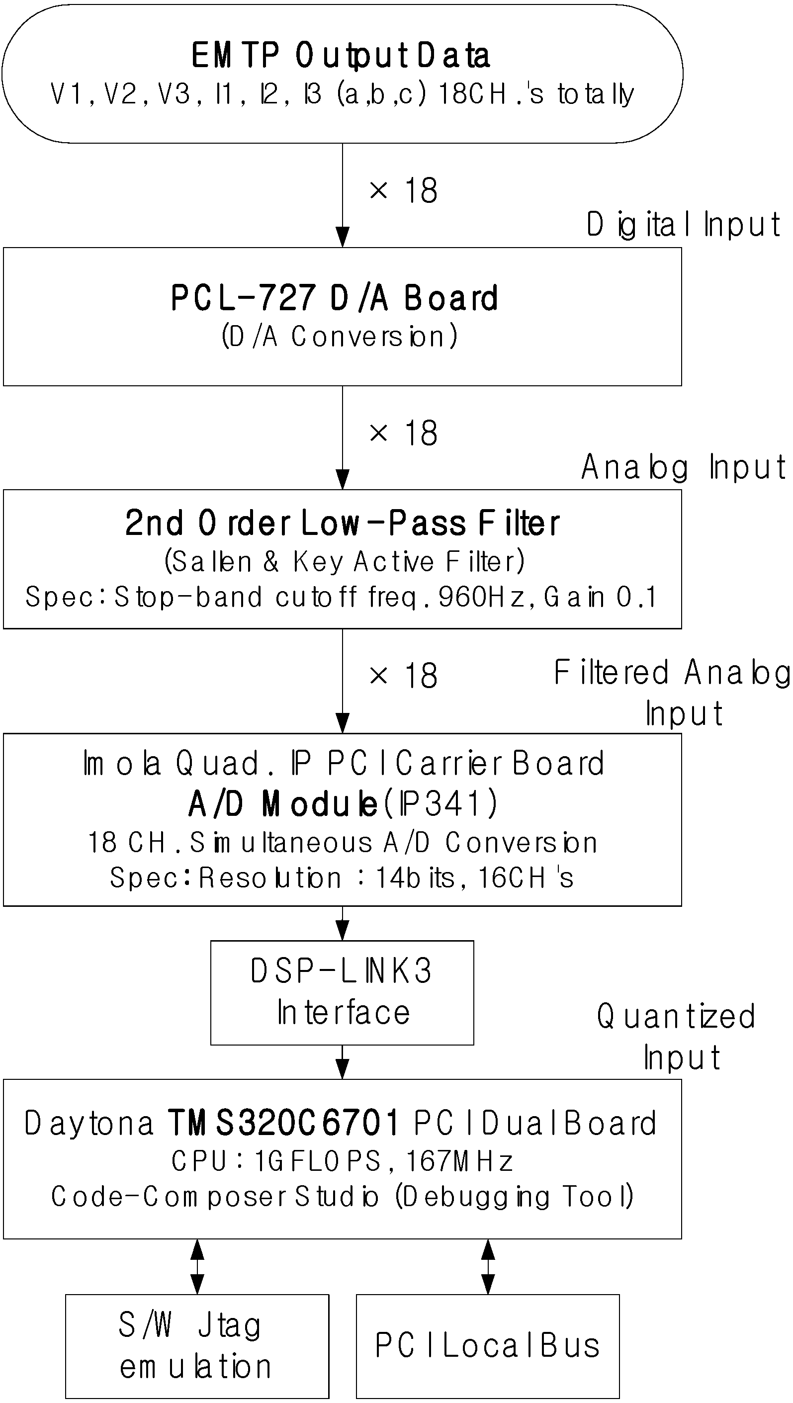
4. Hardware Implementation Test

Figure 16 shows the configuration of the test system. The algorithm was implemented on the TMS320C6701 digital signal processor. The sampling rate is 32 samples/cycle. The currents and voltages of 18 channels are passed through the 2nd Butterworth filters (fc = 960 Hz), which are Sallen & Key active filters, to the 16-bit A/D converter.
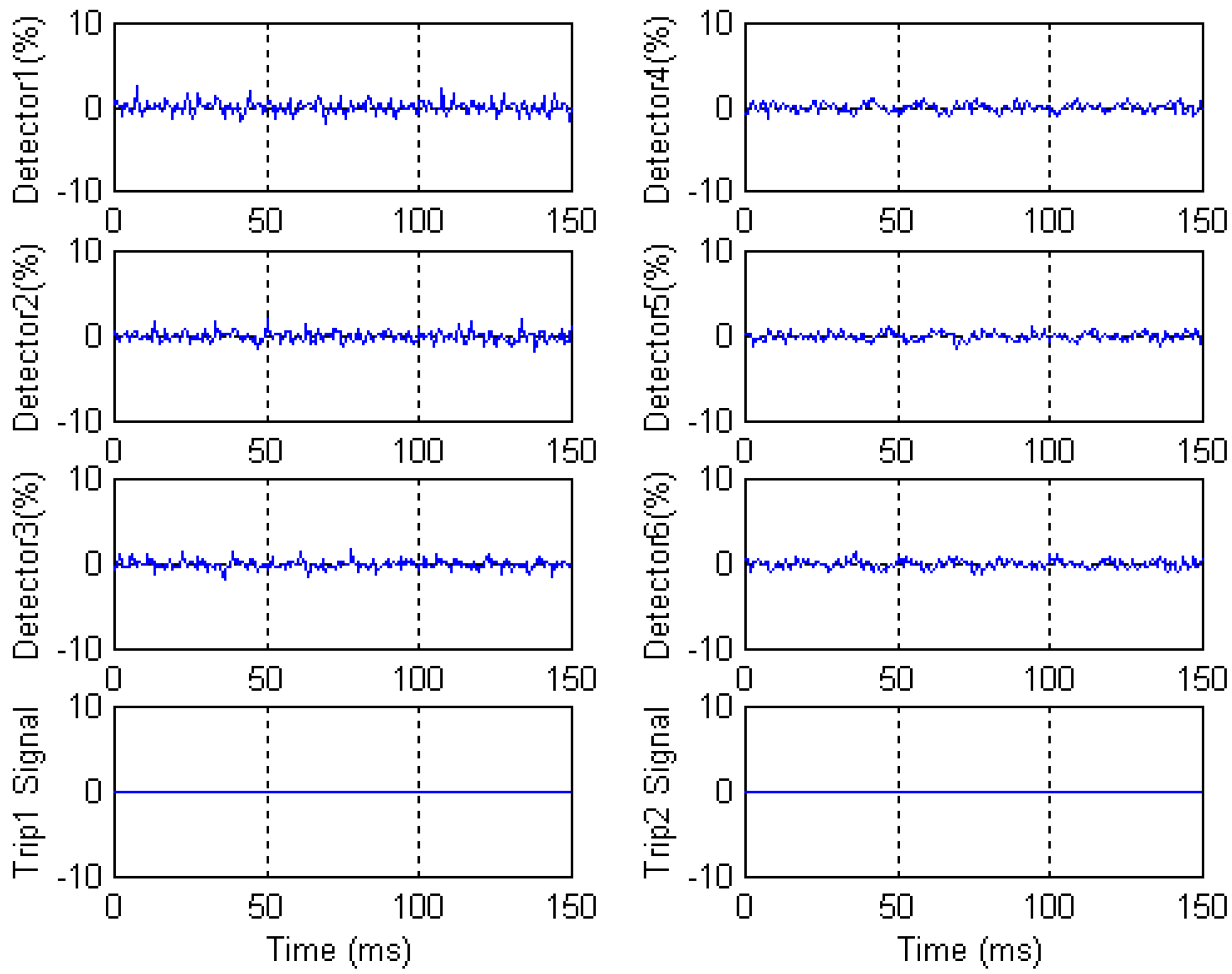
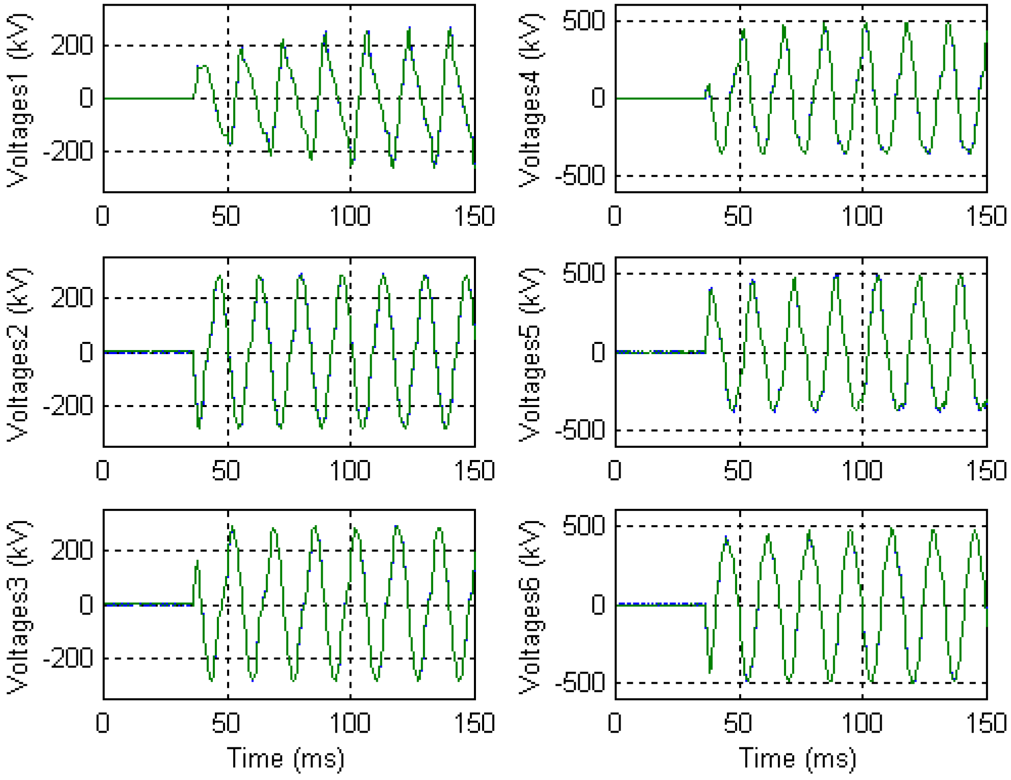
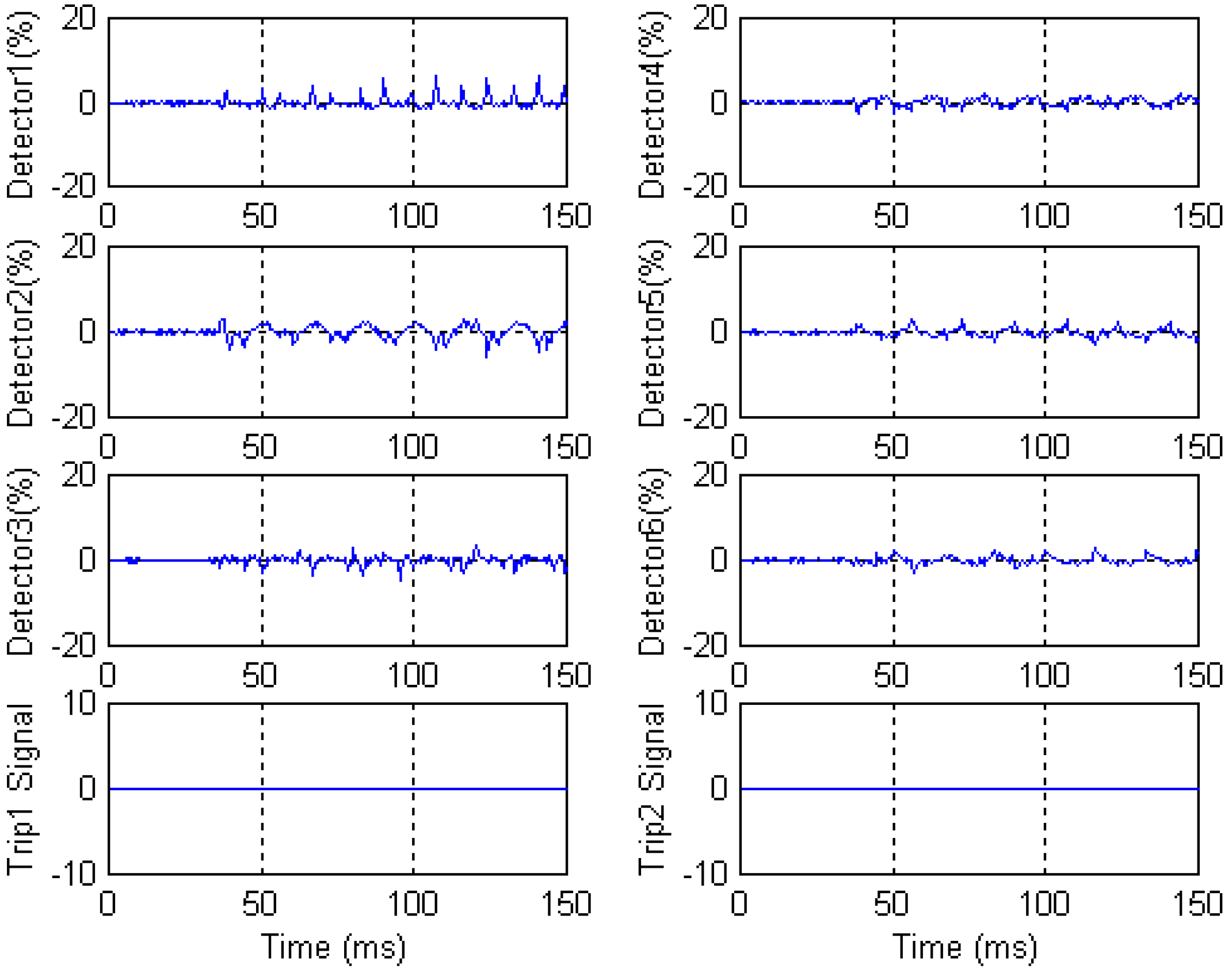
Figure 17 and Figure 18 show the results for Case 1. Noise signals in the hardware result in the larger errors than observed in the simulation results. However, the algorithm performs successfully with a threshold of 5% and a security counter of 4.
Figure 19 shows the results for Case 2. The Trip1 and Trip2 signals are activated 2.6 ms and 3.1 ms after fault occurrence. Consequently, all the test results support the conclusion that a prototype monitoring system, based on the algorithm, can successfully discriminate between internal faults and magnetic inrush.
Figure 15. Detectors and the trip signals for Case 5.
Energies 07 06031 g015
Figure 16. Configuration of hardware implementation.
Energies 07 06031 g016
Figure 17. Two induced voltages of Voltage 1‒3 and two induced voltage differences of Voltage 4‒6 for Case 1.
Energies 07 06031 g017
Figure 18. Detectors and the trip signals for Case 1.
Energies 07 06031 g018
Figure 19. Detectors and the trip signals for Case 2.
Energies 07 06031 g019

5. Conclusions

This paper proposes an algorithm for fault detection, faulted phase and winding identification of a three-winding transformer based on the induced voltages. Nine detectors and a rule are suggested for fault detection for faulted phase and winding identification. The algorithm accurately estimates the induced voltage differences and uses them to discriminate between internal winding faults and normal operating conditions. In addition, the algorithm can identify the faulted winding and its phase in a simple manner.
The results clearly demonstrate that the proposed algorithm remains stable during magnetic inrush and over-excitation conditions, and is not affected by changing the core characteristics. The algorithm successfully detected a wide range of internal faults in a fraction of a cycle. A prototype monitoring system, based on the described algorithm, successfully discriminates between internal faults and normal operating conditions.
The proposed algorithm can not only detect an internal fault but also identify the faulted phase and winding of a three-winding transformer. In addition, it does not require hysteresis data and the operating time is faster than that of conventional harmonically restrained differential relays because it operates in the time domain.

Acknowledgements

This work was supported partly by the National Research Foundation of Korea (NRF) grant funded by the Korea government (MSIP) (No. 2010-0028509), and partly by the National Research Foundation of Korea (NRF) grant funded by the Korea government (MEST) (No.2011-0028065).

Author Contributions

All the authors contributed to this paper. Byung Eun Lee and Yong Cheol Kang mainly proposed the algorithm of this paper. Byung Eun Lee has carried out the simulation tests and Yong Cheol Kang has checked the simulation results. Writing was done by Byung Eun Lee, Jung-Wook Park, Peter A. Crossley, and Yong Cheol Kang. Final review was done by Byung Eun Lee, Jung-Wook Park, Peter A. Crossley, and Yong Cheol Kang.

Nomenclature

Symbols
Definition
v1, v2, v3
Voltages
i1, i2, i3
Currents
R1, R2, R3
Winding resistances
Ll1, Ll2, Ll3
Leakage inductances
e1, e2, e3
Induced voltages
V1, V2
Rated voltages
ϕm
Mutual flux
N1, N2, N3
Number of turns (for 3 ϕ)
v1A, v1B, v1C
Primary voltages (for 3 ϕ)
i1A, i1B, i1C
Primary currents (for 3 ϕ)
v2A, v2B, v2C
Secondary voltages (for 3 ϕ)
i2A, i2B, i2C
Secondary currents (for 3 ϕ)
v3AB, v3BC, v3CA
Tertiary voltages (for 3 ϕ)
i3AB, i3BC, i3CA
Tertiary winding currents (for 3 ϕ)
i3A, i3B, i3C
Line currents (for 3 ϕ)
R1A, R1B, R1C
Primary winding resistances (for 3 ϕ)
Ll1A, Ll1B, Ll1C
Primary leakage inductances (for 3 ϕ)
e1A, e1B, e1C
Primary induced voltages (for 3 ϕ)
R2A, R2B, R2C
Secondary winding resistances (for 3 ϕ)
Ll2A, Ll2B, Ll2C
Secondary leakage inductances (for 3 ϕ)
e2A, e2B, e2C
Secondary induced voltages (for 3 ϕ)
R3AB, R3BC, R3CA
Tertiary winding resistances (for 3 ϕ)
Ll3AB, Ll3BC, Ll3CA
Tertiary leakage inductances (for 3 ϕ)
e3AB, e3BC, e3CA
Tertiary induced voltages (for 3 ϕ)
V1AB, V1BC, V1CA, V2AB, V2BC, V2CA
Rated phase-to-phase voltages (for 3 ϕ)

Conflicts of Interest

The authors declare no conflict of interest.

References

  1. Phadke, A.G.; Thorp, J.S. Computer Relaying for Power Systems; Research Studies Press: Hertfordshire, UK, 1988. [Google Scholar]
  2. Al-Fakhri, B.; Elagtal, I.A. A Unique Current Differential Based Algorithm for Protection of Three-Winding Transformers and Busbars. In Proceedings of the 2001 IEEE Power Engineering Society Winter Meeting, Columbus, OH, USA, 28 January–1 February 2001; pp. 687–692.
  3. Hayward, C.D. Harmonic-current-restrained relays for transformer differential protection. Am. Inst. Electr. Eng. Trans. 1941, 60, 377–382. [Google Scholar] [CrossRef]
  4. Mathews, C.W. An improved transformer differential relay. Electr. Eng. 1954, 73, 645–650. [Google Scholar] [CrossRef]
  5. Sharp, R.L.; Glassburn, W.E. A transformer differential relay with second-harmonic restraint. Trans. Power Appar. Syst. 1958, 77, 913–918. [Google Scholar] [CrossRef]
  6. Einvall, C.H.; Linders, J.R. A three-phase differential relay for transformer protection. IEEE Trans. Power Appar. Syst. 1975, 94, 1971–1980. [Google Scholar] [CrossRef]
  7. Sachdev, M.S.; Sidhu, T.S.; Wood, H.C. A digital relaying algorithm for detecting transformer winding faults. IEEE Trans. Power Deliv. 1989, 4, 1638–1648. [Google Scholar] [CrossRef]
  8. Kang, Y.C.; Lee, B.E.; Kang, S.H.; Kim, S.S.; Lee, J.K. A Transformer Protective Relaying Algorithm Using the Ratio of Induced Voltages. In Proceedings of the IEEE 2001 Power Engineering Society Summer Meeting, Vancouver, BC, Canada, 15–19 July 2001; pp. 109–114.
  9. Kang, Y.C.; Lee, B.E.; Kang, S.H. Transformer protection relay based on the induced voltages. Int. J. Electr. Power Energy Syst. 2007, 29, 281–289. [Google Scholar] [CrossRef]
  10. Saleh, S.A.; Rahman, M.A. Real-time testing of a WPT-based protection algorithm for three-phase power transformers. IEEE Trans. Ind. Appl. 2005, 41, 1125–1132. [Google Scholar] [CrossRef]
  11. Saleh, S.A.; Scaplen, B.; Rahman, M.A. A new implementation method of wavelet-packet-transform differential protection for power transformers. IEEE Trans. Ind. Appl. 2011, 47, 1003–1012. [Google Scholar] [CrossRef]
  12. Tripathy, M.; Maheshwari, R.P.; Verma, H.K. Radial basis probabilistic neural network for differential protection of power transformer. IET Gener. Trans. Distrib. 2008, 2, 43–52. [Google Scholar] [CrossRef]
  13. Tripathy, M.; Maheshwari, R.P.; Verma, H.K. Power transformer differential protection based on optimal probabilistic neural network. IEEE Trans. Power Deliv. 2010, 25, 102–112. [Google Scholar] [CrossRef]
  14. Oliveira, L.M.R.; Cardoso, A.J.M. Application of park’s power components to the differential protection of three-phase transformers. Electr. Power Syst. Res. 2012, 83, 203–211. [Google Scholar] [CrossRef]
  15. Oliveira, L.M.R.; Cardoso, A.J.M. Extended park’s vector approach-based differential protection of three-phase power transformers. IET Electr. Power Appl. 2012, 6, 463–472. [Google Scholar] [CrossRef]
  16. Alencar, R.J.N.; Bezerra, U.H.; Ferreira, A.M.D. A method to identify inrush currents in power transformers protection based on the differential current gradient. Electr. Power Syst. Res. 2014, 111, 78–84. [Google Scholar] [CrossRef]
  17. Babnik, T.; Gubina, F. Fast power transformer fault classification methods based on protection signals. IEE Proc. Gener. Transm. Distrib. 2003, 150, 205–210. [Google Scholar] [CrossRef]
  18. Ngaopitakkul, A.; Kunakorn, A. Internal fault classification in transformer windings using combination of discrete wavelet transforms and back-propagation neural networks. Int. J. Control. Autom. Syst. 2006, 4, 365–371. [Google Scholar]
  19. Bastard, P.; Bertrand, P.; Meunier, M. A transformer model for winding fault studies. IEEE Trans. Power Deliv. 1994, 9, 690–699. [Google Scholar] [CrossRef]
  20. Dommel, H.W. ElectroMagnetic Transients Program. Reference Manual (EMTP Theory Book); Bonneville Power Administration: Portland, OR, USA, 1986. [Google Scholar]

