Article

A Novel Constant-Pressure Pumped Hydro Combined with Compressed Air Energy Storage System

*
Author to whom correspondence should be addressed.
School of Energy and Power Engineering, Xi’an Jiaotong University, Xi’an 710049, Shaanxi, China
Energies 2015, 8(1), 154-171; https://doi.org/10.3390/en8010154
Submission received: 28 August 2014 / Accepted: 19 December 2014 / Published: 26 December 2014
(This article belongs to the Special Issue Sustainable Energy Innovation: Strategies to Accelerate Progress)

Abstract

:
As intermittent renewable energy is receiving increasing attention, the combination of intermittent renewable energy with large-scale energy storage technology is considered as an important technological approach for the wider application of wind power and solar energy. Pumped hydro combined with compressed air energy storage system (PHCA) is one of the energy storage systems that not only integrates the advantages but also overcomes the disadvantages of compressed air energy storage (CAES) systems and pumped hydro energy storage systems to solve the problem of energy storage in China’s arid regions. Aiming at the variable working conditions of PHCA system technology, this study proposes a new constant-pressure PHCA. The most significant characteristics of this system were that the water pump and hydroturbine work under stable conditions and this improves the working efficiency of the equipment without incurring an energy loss. In addition, the constant-pressure PHCA system was subjected to energy and exergy analysis, in expectation of exploring an attractive solution for the large-scale storage of existing intermittent renewable energy.

1. Introduction

With the increasing depletion of traditional fossil energy sources, the use of renewable energy has been attracted more and more attention. The development of renewable energy has become a primary task in many countries [1]. However, due to the inherent randomness and volatility of wind energy, solar energy, bio-energy, etc., the development of new energy sources is a huge challenge confronted by countries all over the world. How to solve the volatility of renewable energy sources is the key issue of the development and utilization of renewable energy in the future [2,3]. In recent years, China’s wind and solar power generation capacity has developed rapidly. Since 2010, the installed capacity of wind power in China has been ranked first in the world, and as of the end of 2013, the cumulative installed capacity of China’s wind turbines exceeded 90 GW. Unfortunately, due to the randomness and intermittence of wind energy, as well as the poor peak shaving ability of the existing power grid, a considerable proportion of the wind power generated failed to reach the power grid. In 2013 alone, China’s wasted wind power exceeded 15 TW·h. It can be expected that this loss will increase with the further expansion of the installed wind power capacity. Energy storage technology can improve the supply capacity of power system, its energy utilization efficiency, and the security and reliability [4], and improve the utilization of new energy by storing excess power in power utilization troughs and releasing it during power utilization peaks. At present, there are two technologies suitable for energy storage in large-scale power systems, namely, pumped hydro energy storage technology and compressed air energy storage (CAES) technology [5,6].
Pumped hydro energy storage is currently the most practical and mature energy storage technology available for electricity [7,8,9]; according to the data from the Electric Power Research Institute (EPRI), pumped hydro energy storage ranks first in the global energy storage market and accounts for more than 99% of the total installed capacity. However, owing to the shortcomings of this technology, including large investment requirement, long construction period, being affected by topography and its influence on regional ecology and geology, the promotion of pumped hydro energy storage technology is limited in China [10,11,12].
Germany established a demonstration project for a CAES station in the 1970s to 1980s, which is still in operation today. At present, operating power stations include America’s Alabama project and Germany’s Huntorf project [13]. In the 21st century, CAES systems, and especially the issues related to the feasibility thereof have been investigated [14,15,16,17,18,19]. Grazzini et al. [19] proposed an advanced adiabatic CAES system, which dispensed with the combustion chamber of traditional CAES systems and improved the heat utilization ratio. Kim et al. [20] developed an energy storage system by maintaining a constant voltage using a fixed head of water. This system improved the efficiency of CAES and solved the problem of variable working conditions. However, the biggest problems facing CAES systems remain the large intermediate cooling circulating water flow in the multistage compression storage process, the stability and sealing problem of the underground air storage cavern, as well as the auxiliary heating problem of air in the power generation process by compressed air expansion. Therefore, CAES power stations require specific geological conditions, favorable water resources, and an abundant natural gas supply.
Assuming that a pressure vessel bearing the compressed air at certain internal pressure was connected to a pump by a pipeline and valve (Figure 1), when the pump delivers water to the vessel, a virtual dam is built between the lower tank of the pump and the interior of the pressure vessel. For example, when the internal pressure in the pressure vessel P is 5 MPa, the bottom height of the virtual dam h is 500 m.
Figure 1. The physical model of pumped hydro combined with compressed air energy storage system (PHCA).
Energies 08 00154 g001
Based on this principle, Wang et al. [21] proposed a model for a pumped hydro energy storage system to fundamentally solve the aforementioned problems by using compressed air that was used to seal the pressure vessel to artificially build that virtual dam. By controlling the air pressure in the vessel, the fall, upstream and downstream of the virtual dam, was changed. The energy storage system consisted of: a storage vessel, a water tank connected to atmosphere, a water pump, and a hydroturbine-driven electrical generating set. However, since the pressure in the pressure vessel fluctuates with changing water level, the power generation process and energy storage process are all variable. Considering the design condition deviations from the hydroturbine and water pump, its energy storage efficiency and power generation quality are likely to be decreased. To ensure stable operation, a novel constant-pressure pumped hydro combined with compressed air energy storage system (PHCA) was proposed. Moreover, the thermodynamic performance of the system and factors influencing the system performance from a theoretical standpoint was discussed. The results provided theoretical support for the application of the system.

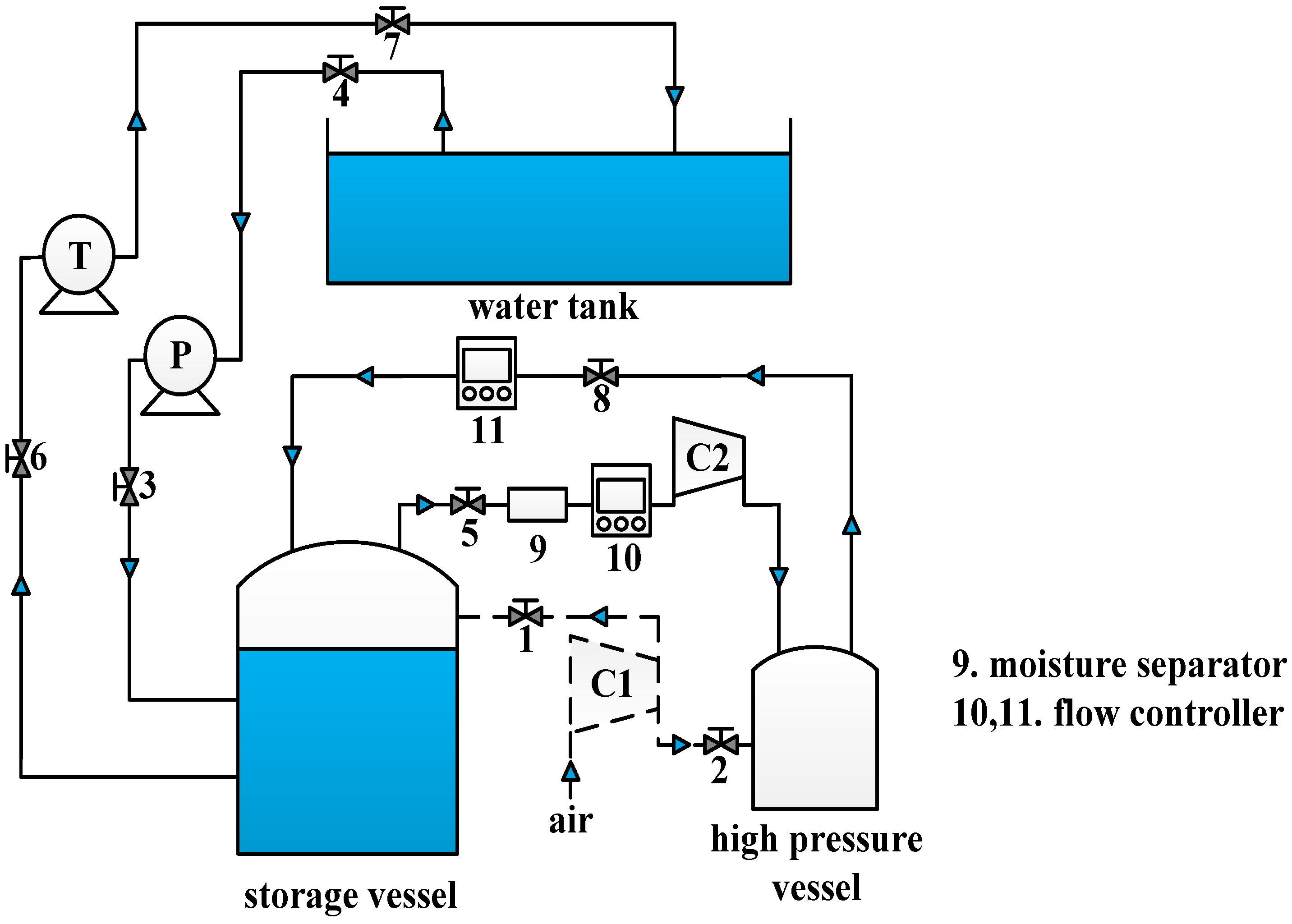
2. Physical Model and Working Principles

Figure 2 shows the constant-pressure PHCA:
(1)
Initial compression process: by opening the valves 1 and 2, the storage vessel and high pressure vessel were firstly pressurised to the preset pressure P1 through compressor 1. Closing valves 1 and 2, stops compressor C1.
(2)
Water injection process for energy storage: when needing energy storage, valves 3 and 4 were opened to transfer the water in the water tank to the storage vessel through the high-pressure water pump. Meanwhile, valve 5 and compressor C2 were started to pump the air in the storage vessel into the high pressure vessel. In this way, the pressure P1 in the storage vessel was kept constant regardless of the rising water level. As the air in high pressure vessel was compressed to target pressure P2, valves were closed and energy storage ended.
(3)
Power generation process: valve 6, valve 7, and throttle valve 8 were opened and then the hydroturbine generated power under the high pressure. Since P2 > P1, the air at P2 in the high pressure vessel flowed spontaneously after being throttled to P1 by throttle valve 8. The pressure P1 in the storage vessel was thereby kept constant as the water level decreased. Subsequently, the water flowing through the hydroturbine returned to the water storage tank to allow it to be recycled. The water pump and hydroturbine in the system worked at a constant pressure throughout the process.
Figure 2. Schematic of the constant-pressure PHCA.
Energies 08 00154 g002

3. Thermodynamic Analysis

To analyze the new constant-pressure PHCA, the following assumptions were made:
(1)
The gas only consists of nitrogen which is scarcely soluble in water and acts as an ideal gas.
(2)
The hydraulic water is incompressible in the thermodynamic calculations.
(3)
The high pressure vessel is an adiabatic container.
(4)
In the gas and liquid flows, negligible potential and kinetic energy effects, absence of phase change, and no chemical reaction were assumed.
(5)
There is no pressure loss in the pipeline of gas and liquid flows.

3.1. Initial Compression Process

To improve the working capacity per unit working medium, the water should be pumped to a higher level in a traditional pumped hydro energy storage station to increase the gravitational potential of any upstream water. However, in the new constant-pressure PHCA, the storage vessel should be injected with air at certain pressure in advance. Since this process happens once in the whole system and was deemed preparatory, a compressor with a low flow rate was used for cost-effectiveness. Moreover, due to the large volume of the storage vessel, the air input process was slow. It was assumed that the storage vessel was endowed with sufficient heat exchange capacity to its exterior to ensure a constant temperature of the air in the storage vessel. Therefore, the initial compression process was treated as approximately isothermal process. When the storage vessel was inflated, the work consumption per unit mass is:
w = R gn T 0 ln ( p 1 p 0 )
where p0 is the initial pressure of storage vessel; and p1 is the terminal pressure. If the storage vessel has a volume Vh, according to the state equation of an ideal gas:
d m a = d ( p V h R gn T 0 ) = V h R gn T 0 d p
The mass of the inflated air is:
m a = p 0 p 1 d m = p 0 p 1 V h R gn T 0 d p = V h R gn T 0 ( p 1 p 0 )
The work consumption of the inflating process is:
W c1 = 1 2 w d m a = p 0 p 1 V h ln ( p p 0 ) d p = p 0 V h ( p 1 p 0 ln p 1 p 0 p 1 p 0 + 1 )
When the high pressure vessel is inflated, the work consumption per unit mass is Equation (1): high pressure vessel was mainly used to maintain a constant pressure in the whole pumping and gas-compression process. Being similar to that of the storage vessel, the inflation process was also isothermal. If the volume of the high pressure vessel is Vs, according to the state equation of an ideal air:
d m a = d ( p V s R gn T 0 ) = V s R gn T 0 d p
The mass of pressurized air is:
m a = p 0 p 1 d m = p 0 p 1 V s R gn T 0 d p = V s R gn T 0 ( p 1 p 0 )
The total work in the inflating process is:
W c1 ´ = 1 2 w d m a = p 0 p 1 V s ln ( p p 0 ) d p = p 0 V s ( p 1 p 0 ln p 1 p 0 p 1 p 0 + 1 )

3.2. Water Injection Process

The vessel was filled with water by the high pressure water pump. As the water level increased, the pressure of air in the storage vessel increased. Using compressor C2, the air was compressed in the high pressure vessel to maintain a constant pressure in the storage vessel during the water-filling process. After filling, the mass of water used was:
m w = ρ w V w
where ρw is the density of water; and Vw is the volume of water in the storage vessel. When neglecting the height difference between the water tank and the storage vessel, the water pump work per unit mass is:
w p = p 0 p 1 1 ρ w d p = p 1 p 0 ρ w
The total pump work is as follows:
W p = w p m w / η p = ( p 1 p 0 ) V w p
Substituting the hydrosphere ratio ε = V w V h V w into Equation (10) gives:
W p = ( p 1 p 0 ) V h ε 1 + ε p

3.3. Constant Pressure Process

In the inflation process for the high pressure vessel, the mass of air in the vessel increased as compressor C2 continuously stored the compressed air for delivery to the high pressure vessel, thus following the variations of pressure and temperature. Taking the high pressure vessel space as the control volume, the following equation applies to the inflation and energy storage processes according to the first law of thermodynamics:
δ Q = d E cv + ( h out + v out 2 2 + g z out ) δ m out ( h in + v in 2 2 + g z in ) δ m in + δ W i
During inflation, while ignoring the kinetic energy and potential energy of the gas, the thermodynamic energy (stored energy) controlled the volume so that:
δ Q = d E cv + h out δ m out h in δ m in + δ W i
Because the high pressure vessel is adiabatic, δQ = 0; there is no external work δWi = 0 and no gas flow, thus δmout = 0; Therefore:
d U h in δ m in = 0
In an infinitesimal process, the gas inflow is equal to the increased amount of gas within the control volume, the mass balance equation is:
δ m in = d m
The specific enthalpy of the gas inflow in the process hin = cpT2, therefore:
c p T 2 d m = d ( m u ) = m d u + u d m = c V m d T + c V T d m
By iteration:
m c V d T = ( c p T 2 c V T ) d m
d m m = d T k T 2 T
Since d p p + d V V d m m d T T = 0 and dV = 0, it is given that:
d p p = k T 2 ( k T 2 T ) T d T
By integrating:
T s2 = k T s1 T s1 T 2 + p s1 p s2 ( k T s1 T 2 )
where ps1 is the initial pressure in the high pressure vessel; ps2 is the pressure in the high pressure vessel after expansion; T2 is the air inflow temperature; Ts1 is the initial temperature of the high pressure vessel; and Ts2 is the temperature of high pressure vessel after inflation.
When high pressure vessel was used to deflate to the storage vessel, the space in the high pressure vessel was treated as the control volume. Since there was no gas inflow, δmin = 0. According to the first law of thermodynamics and the assumptions above, the following equation was available (after some simplification):
d U + h out δ m out = 0
In the infinitesimal process, since the gas deflation volume equaled the decreased volume of the gas in the control volume, the mass equation is:
δ m out = d m
While deflating, the specific enthalpy of the deflating gas was equal to the specific enthalpy of the gas in the vessel at that time, namely, hout = h. Therefore:
d U = h d m
Namely mdu + udm = hdm.
As for an ideal gas, the formula can be rewritten as:
c p T d m = c V m d T + c V T d m
By sorting:
d m m = 1 k 1 d T T
Since d p p + d V V d m m d T T = 0 and dV = 0:
d T T = k 1 k d p p
Integration yielded:
T s3 = k T s1 T s1 T 0 + p s1 p s2 ( k T s1 T 0 ) ( p s2 ´ p s1 ´ ) k 1 k
where ps1 is the initial pressure of high pressure vessel; ps2 is the pressure of the high pressure vessel after deflation; and Ts3 is the temperature of the high pressure vessel after deflation.
According to the Equation (27), the initial temperature of the high pressure vessel was 298 K. Since the air entering the high pressure vessel from the compressor outlet was T2, it can be inferred that the temperature variation in the high pressure vessel was related to the pressure variation range of the high pressure vessel. Therefore, according to different pressure ratios, the temperature of the high pressure vessel after deflation can be found, as shown in Figure 3.
Figure 3. The variations in high pressure vessel temperature with pressure ratio.
Energies 08 00154 g003
As shown in Figure 3, in a certain pressure ratio range, the temperature difference between the high pressure vessel after deflation and the initial temperature (298 K) was not more than 5 K. Therefore, the air in the high pressure vessel was deemed to have retained its initial state after a series of inflation/deflation processes. The unit work consumption of adiabatic compressed inflation is:
w = k k 1 R gn T 0 [ ( p p 1 ) k 1 k 1 ) ]
where k is the adiabatic index; p1 is the constant pressure in the storage vessel; and p2 is the terminal pressure in the high pressure vessel. If the volume of the compressed air is Vw, the mass of the compressed air used to maintain a constant pressure in the storage vessel is:
d m b = V w k T 0 R gn d p
To maintain constant pressure the total power consumption is:
W c 2 = p 1 p 2 w d m b / η c = V w k 1 [ k 2 k 1 p 1 1 k k ( p 2 2 k 1 k p 1 2 k 1 k ) ( p 2 p 1 ) ] / η c

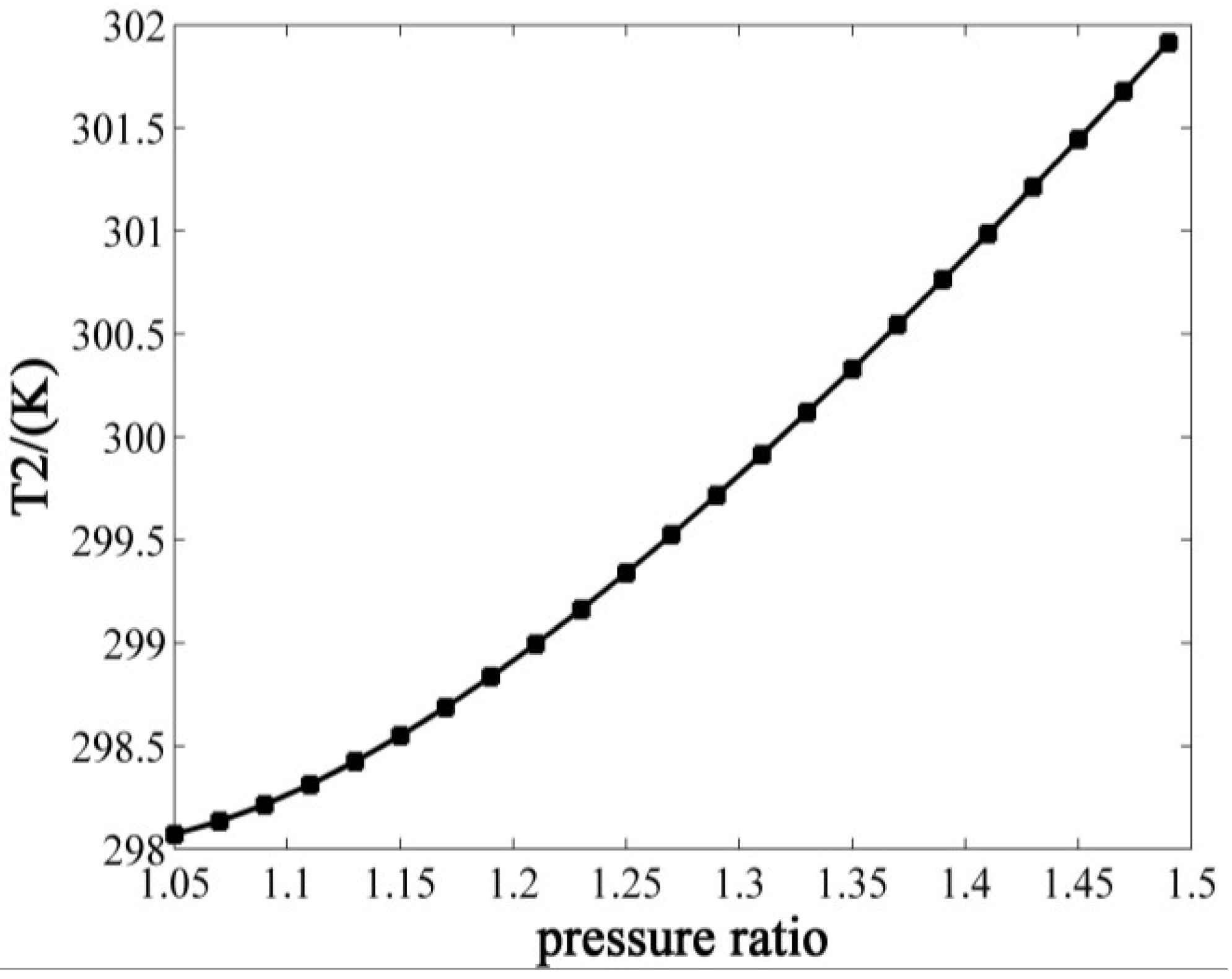
3.4. Power Generation Process

When generating power, the high-pressure air in the high pressure vessel was spontaneously discharged and delivered to the storage vessel to maintain the constant pressure therein. Therefore, the work done by the water per unit mass in the hydroturbine is:
w t = p 1 p 0 ρ w
The total work output of the hydroturbine is:
W t = w t m w η t = ( p 1 p 0 ) V w η t
Substituting the hydrosphere ratio ε = V w V h V w into Equation (32) gives:
W t = ( p 1 p 0 ) V h ε 1 + ε η t

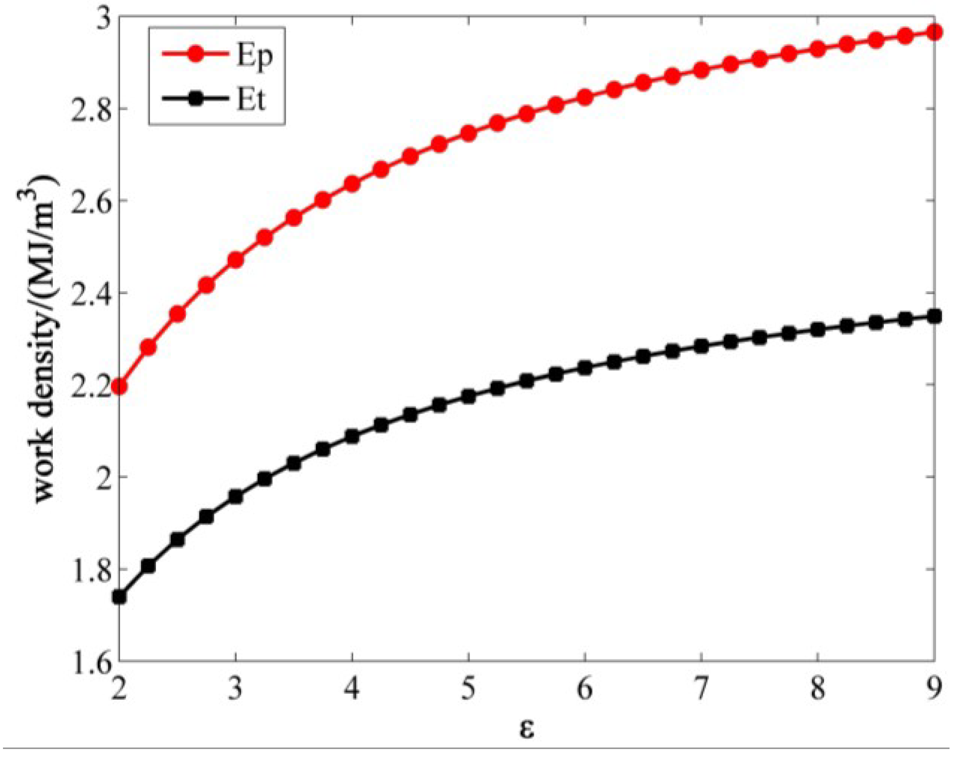
3.5. The Influences of Work Density

In constant-pressure PHCA system, the storage vessel is one of the key components: it ensures the normal operation of the whole system and its cost is related to the overall cost of the whole system. Therefore, the input and output capacities of the pressure vessel per unit volume acts forms an important basis for the optimization of the system. Table 1 shows the values of main parameters used in the model.
Table 1. Main parameters and their values of constant-pressure PHCA system.
ParameterUnitValue
Ambient temperatureK298
Ambient pressurePa100,000
Volume of storage vesselm340
Volume of high pressure vesselm35
Adiabatic index-1.4
Gas constantJ·kg−1·K−1296
Constant pressure specific heatJ·kg−1·K−11,042
Density of waterkg·m−31,000
Efficiency of water pump%88
Efficiency of hydroturbine%90
The work density is defined by:
E p = W p V h = ( p 1 p 0 ) ε 1 + ε p
E t = W t V h = ( p 1 p 0 ) ε 1 + ε η t
According to the two equations above, the relationship between work density, pre-set pressure, and hydrosphere ratio can be obtained. As shown in Figure 4 and Figure 5, with increased pre-set pressure and water-air volume ratio, the work density of the storage system increased.
Figure 4. The variation of work density with pre-set pressure.
Energies 08 00154 g004
Figure 5. The variation of work density with water-air volume ratio.
Energies 08 00154 g005

4. Energy and Exergy Analysis

The first law of thermodynamics states that energy is conserved in a fundamental aspect of the energy concept that has been widely used for analysis of energy utilization. The second law of thermodynamics establishes the difference in the quality of different forms of energy and explains why some processes can spontaneously occur while others cannot. It is essential to perform a thorough analysis of both quantity and quality of the energy in the constant-pressure PHCA system [22,23,24].

4.1. Energy Analysis

Energy analysis is based on the first law of thermodynamics, which is based on the conservation principle of energy in quantity. As suggested by the working process of the constant-pressure PHCA, when the air in the storage vessel was compressed to the pre-set pressure, compressor 1 stopped working in subsequent energy storage and power generation processes provided that the high pressure vessel was sealed. Therefore, the system efficiency was expressed as:
η = W t W p + W c 2

4.2. Exergy Analysis

Exergy is the maximum theoretical work obtainable from an overall system consisting a system and the environment as the system comes into equilibrium with the environment [24]. Exergy analysis is a method that uses the conservation of mass and conservation of energy principles together with the second law of thermodynamics for the analysis while exergy destruction is the measure of irreversibility which is the source of performance loss [25]. The exergy analysis assessing the magnitude of exergy destruction identifies the equipment, the magnitude and the source of thermodynamic inefficiencies in an energy storage system. Therefore, the exergy analysis would help to provide an efficient system with minimizing the exergy destruction in the system [26].

4.2.1. The Exergy Balancing Relationship in a Stable Flowing System

The exergy balancing relationship for a stable flowing system is expressed as:
E L = E in E out
where Ein is the exergy inflow to the sytem; Eout is the exergy outflow from the sytem; and EL is the exergy loss in the system. The exergy inflow or outflow of the system can be inferred by the mass flow or work and heat transmission:
E in = E m , in + E q , in
E out = E m , out + E q , out
where Em,in is the exergy transmitted by the mass inflow system; Em,out is the exergy transmitted by the mass outflow system; Eq,in is the exergy transmitted by the work and heat inflow system; and Eq,out is the exergy transmitted by the work and heat outflow system.
According to the exergy transmitted by the mass flow:
E m , in E m , out = G m [ ( h in h out ) T 0 ( s in s out ) ]
As for ideal gas with constant specific heat:
h in h out = c p ( T in T out )
s in s out = c p ln T in T out R g ln p in p out
where cp is the specific heat at constant pressure; and Rg is the ideal gas constant.
In the liquid medium, the volume variations in the assumed incompressible liquid were ignored, namely dV = 0, and thus:
h in h out = c ( T in T out ) + p in p out ρ
s in s out = c ln T in T out
where c is the specific heat capacity of the liquid.
According to the exergy transmitted by the inflow system induced by heat:
E q , in = ( 1 T 0 T ) δ Q in
According to the exergy transmitted by the outflow system induced by heat:
E q , out = ( 1 T 0 T ) δ Q out
where T0 is the ambient temperature.

4.2.2. Exergy Analysis of Each Component of the System

4.2.2.1. Exergy Analysis of the Compressor

The exergy loss was:
E c , L = E c , in E c , out = W C + E c , m , in E c , m , out
Therefore, the exergy efficiency was:
η E , C = E c , m , out E c , m , in W C

4.2.2.2. Exergy Analysis of the Water Pump

The exergy loss was:
E p , L = E p , out E p , in = E p , m , out E p , m , in E p , W , in
Therefore the exergy efficiency was:
η E , p = E p , m , out E p , m , in E p , W , in

4.2.2.3. Exergy Analysis of the Hydroturbine

The exergy loss was:
E t , L = E t , in E t , out = E t , m , in E t , m , out E t , W , in
Therefore, the exergy efficiency was:
η E , t = E t , m , in E t , m , out E t , W , in

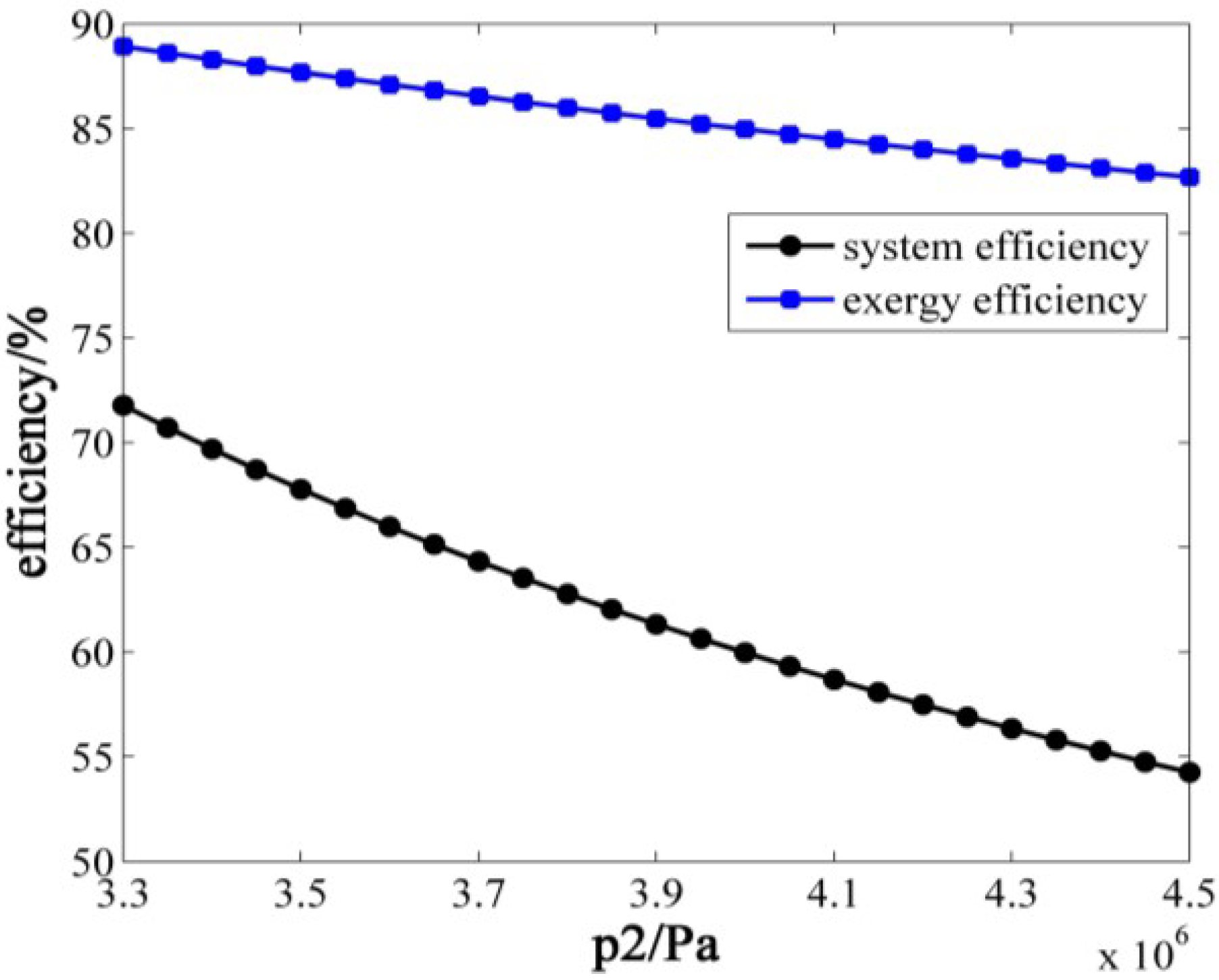
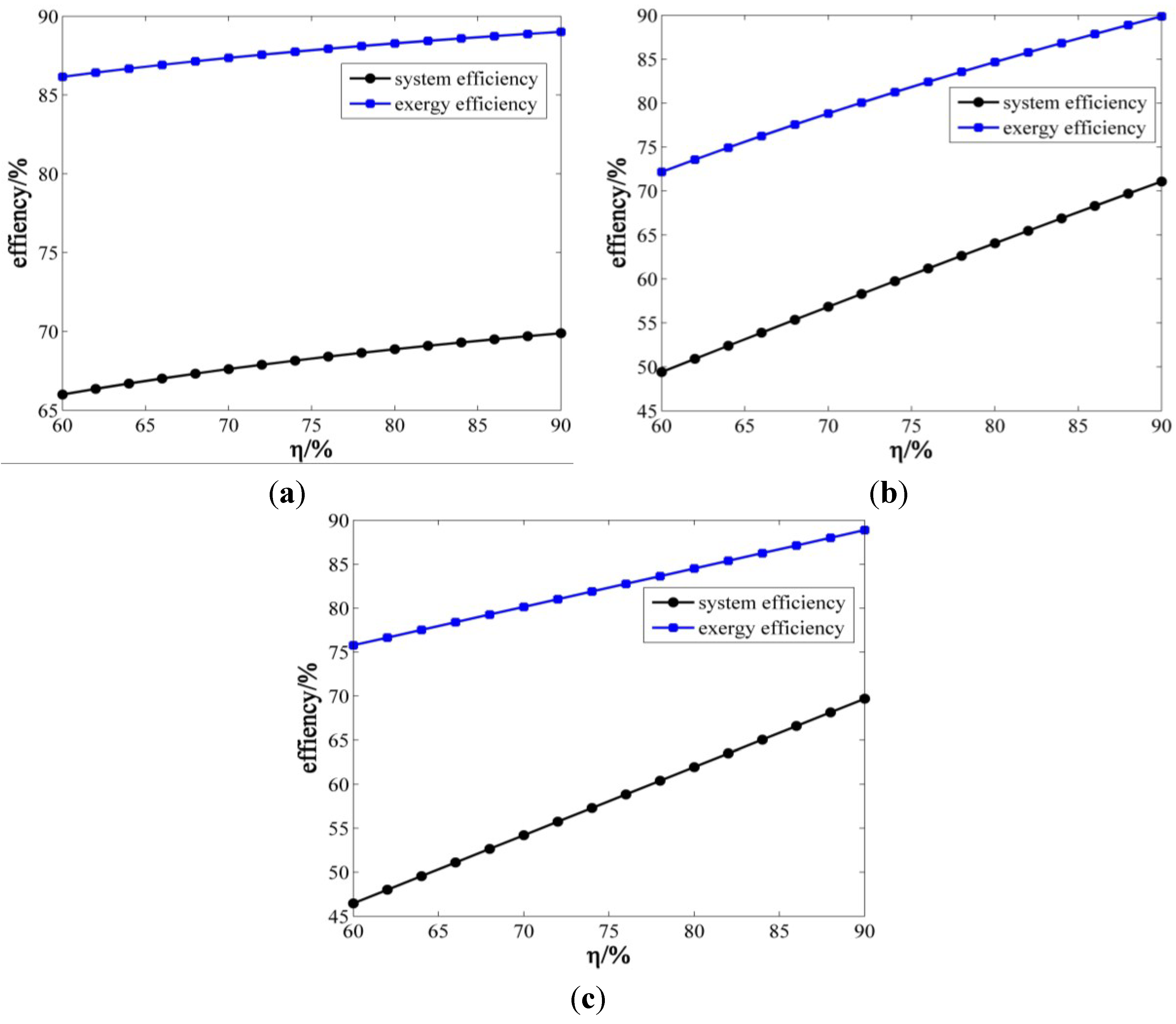
4.2.3. The Influencing Factors of the Exergy Efficiency

The exergy loss of the system was:
E x , L = E x , pay E x , gain
Therefore, the exergy efficiency of the system was:
η E x = E x , gain E x , pay

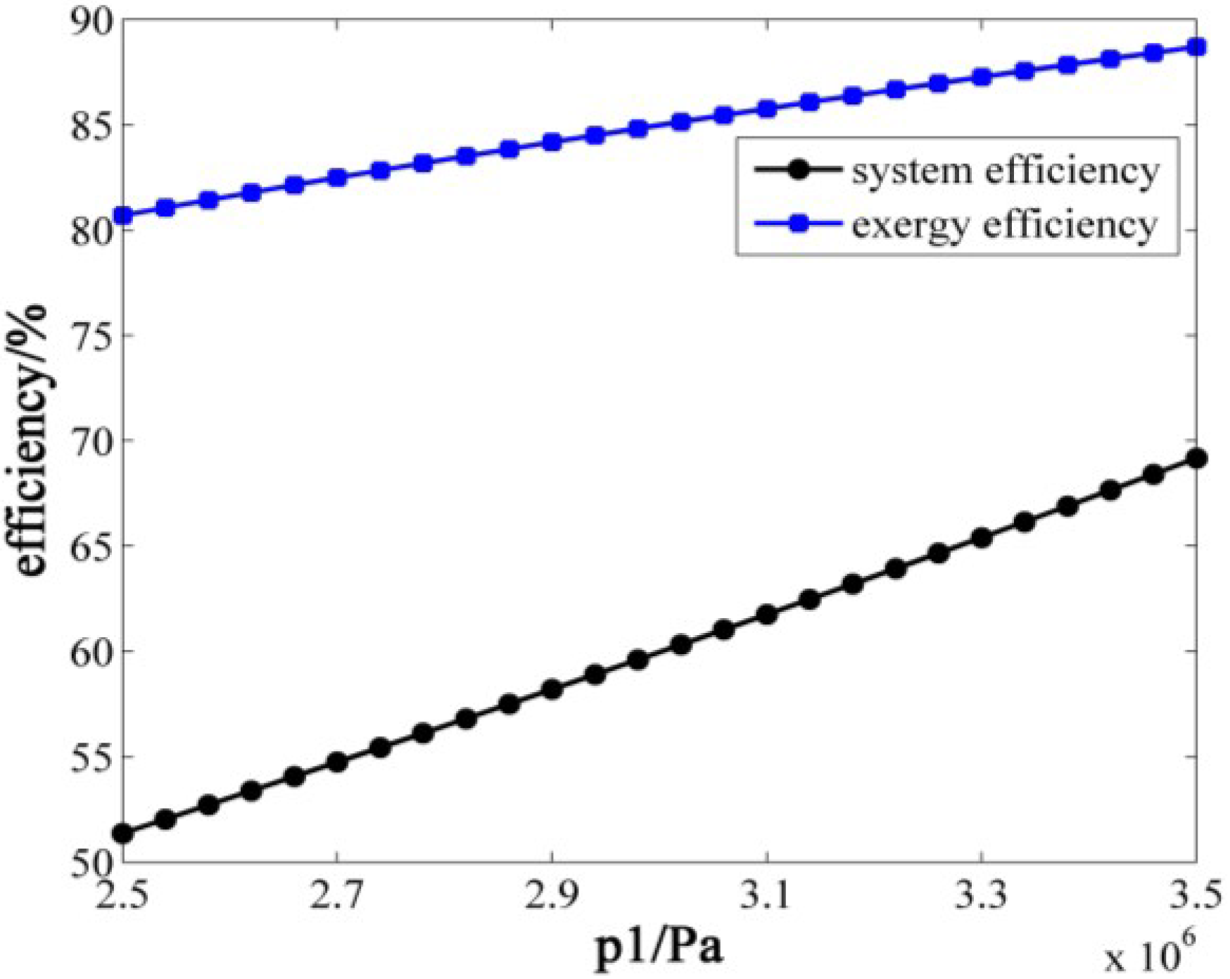
5. Results and Discussion

Energy and exergy analysis were performed for the constant-pressure PHCA system. When changing the pre-set pressure in the storage vessel and maintaining pressure Ph to a level below pressure Ps in the high pressure vessel, the variations of the system efficiency and exergy efficiency with a pre-set pressure were then obtained. Figure 6 shows that both the system efficiency and the exergy efficiency of the system increased with increased pre-set pressure. While both the system efficiency and the exergy efficiency were not sensitive to the water-air volume ratio, the energy intensity of the system could be improved by increasing the water-air volume without influencing the system efficiency and exergy efficiency that within the allowable volume range for the storage vessel.
Figure 6. The variations of system efficiency and exergy efficiency with pre-set pressure.
Energies 08 00154 g006
When changing the pressure in the high pressure vessel while maintaining pressure Ps at a level above pressure Ph in the storage vessel, the variations in system efficiency and exergy efficiency with pressure in the high pressure vessel could be obtained. It can be seen from Figure 7 that both the system efficiency and the exergy efficiency of the system decreased by the increased pressure in the high pressure vessel. It meant that when Ph was constant, the smaller the pressure difference between storage vessel and high pressure vessel, the higher the proportion of the energy utilization in the constant-pressure PHCA.
Figure 7. The variation of system efficiency with pressure in the high pressure vessel.
Energies 08 00154 g007
Figure 8 shows the system efficiency and the exergy efficiency versus its mechanical efficiency: with increased machinery efficiency the system efficiency and the exergy efficiency increased constantly, but the rate of increasing extent with different factors was different.
Figure 8. The variation of system efficiency with mechanical efficiency: (a) the variation of compressor efficiency; (b) the variation of water pump efficiency; and (c) The variation of hydroturbine efficiency.
Energies 08 00154 g008
Both the system efficiency and exergy efficiency increased slowly with increasing compressor efficiency, while the system efficiency and exergy efficiency showed an obvious upward trend as the water pump and hydroturbine efficiency increased. In the aspect of the system efficiency, it was mainly because that the compressor only increases the pressure of the air, the work done by water pump and hydroturbine on the other hand, was much larger than that done by compressor. In the aspect of the exergy efficiency, due to the fact the work done by compressor accounted for only a small proportion of the total work, the irreversible destruction of the compressor efficiency showed little influence on the exergy efficiency of the whole system. Moreover, compared with the hydroturbine efficiency, the pump efficiency exerted a greater influence on the exergy efficiency of the whole system. Making sure the low exergy destruction of hydroturbine and water pump was the important issue to improve the quality of energy consumption which meant that the efficiency of water pump and hydroturbine was the key issue to improve the system performance. The results from Figure 6, Figure 7 and Figure 8 confirm that the exergy efficiency of the proposed system was much higher than that of the CAES systems [16]. This finding was mainly attributed to the following reasons: first, the efficiency of the hydroturbine and water pump was both higher than that of the compressor and expander; second, auxiliary heating systems were not required in the proposed system while the exergy destruction of the intercooler and external combustion heater was high.

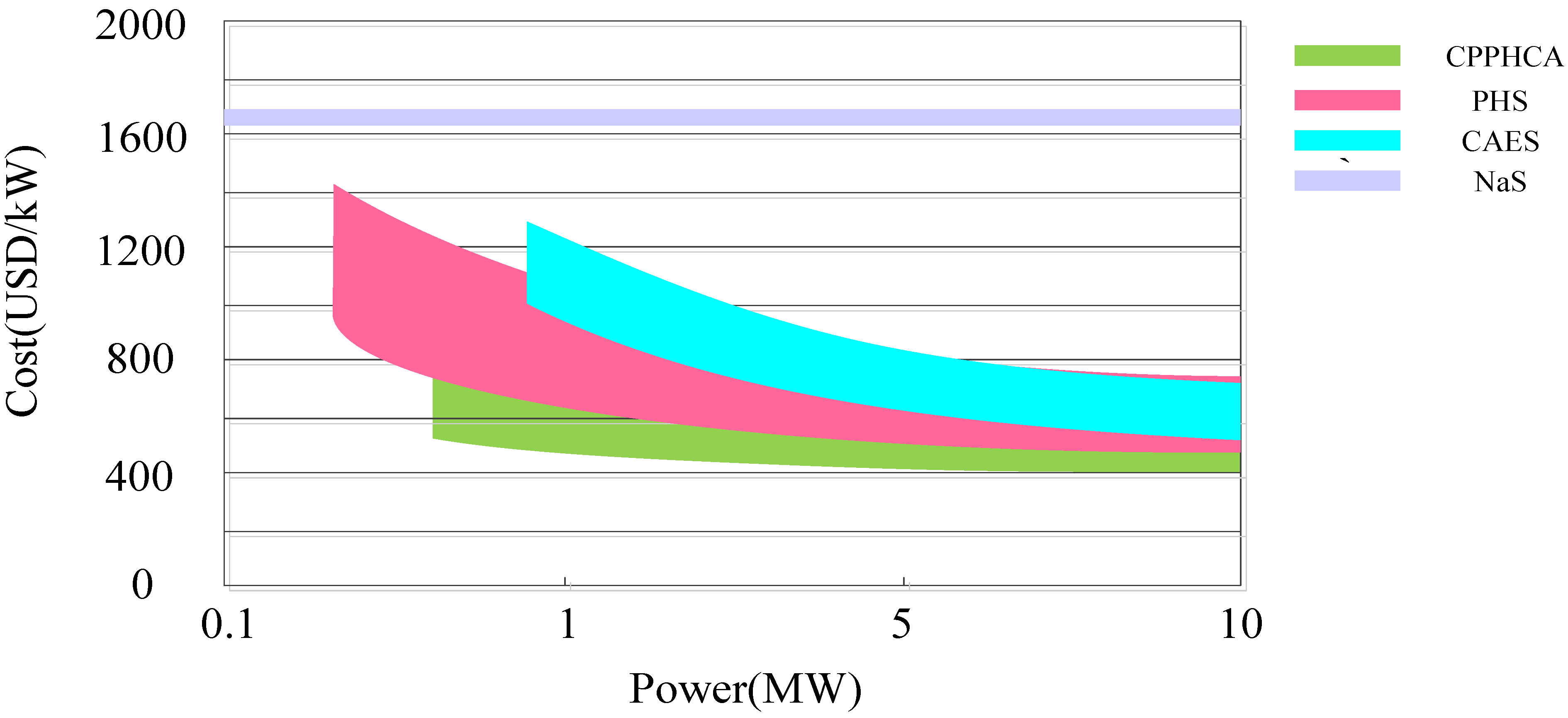
6. Economic Analysis

Modeling and simulation activities were being carried out to evaluate this novel system. Figure 9 summarizes the economic aspects of constant-pressure PHCA (CPPHCA), pumped hydro storage (PHS), CAES and NaS battery [27,28]. Figure 9 presents the cost range instead of an accurate cost at each power with considering the cost of equipment, construction materials, labor and many other aspects in different places. The constant-pressure PHCA shows better economies than that of the other three mainly due to its simple structure. Furthermore, with considering its site independent nature and environmentally friendly, the proposed energy storage system offers the potential to be widely built.
Figure 9. Economic comparison of energy storage system. CPPHCA: constant-pressure PHCA; PHS: pumped hydro storage; and CAES: compressed air energy storage.
Energies 08 00154 g009

7. Conclusions

In this paper, the analysis of the constant-pressure PHCA suggested that it was feasible with regard to both its high efficiency and low exergy destruction at a low cost compared with other energy storage systems. The work density of the storage system increased with increasing both pre-set pressure and water-air volume ratio. With increased pre-set pressure, the system efficiency increased; the system efficiency decreased with increasing pressure in the high pressure vessel. The system efficiency was proportional to the efficiency of compressor, water pump and hydroturbine.
The exergy efficiency of the whole system was less influenced by the pressure in the high pressure vessel and the efficiency of the compressor, while it could be improved by rising the pre-set pressure in the storage vessel and enhancing the working efficiency of either or both of the hydroturbine and water pump. Both the system efficiency and the exergy efficiency have nothing to do with water-air volume ratio. The constant-pressure PHCA ensured that the hydroturbine and water pump can operate at their rated working conditions with high efficiency which could improve the energy utilization level. Therefore, the constant-pressure PHCA would have a broad application prospects in the future.

Acknowledgments

This work was supported by the National High-Technology Research and Development Program (“863” Program) of China (2012AA052505) and by the Chinese National Natural Science Funds (51176145).

Author Contributions

Erren Yao conducted the detailed calculations, simulations and he was responsible for drafting and revising the whole paper; Huanran Wang provided the original idea and contributed to revising the paper; Long Liu revised the paper; and Guang Xi provided the main technical guidance and gave some valuable comments on revising the paper.

Nomenclature

p
Pressure
T
Temperature
V
Volume
k
Adiabatic index
ρ
Density
Cp
Constant pressure specific heat
Rg
Gas constant
ε
Water-air volume ratio
η
Efficiency
m
Mass

Subscripts

w
Water
a
Air
p
Water pump
t
Hydroturbine
c
Compressor
h
Storage vessel
s
High pressure vessel

Conflicts of Interest

The authors declare no conflict of interest.

References

  1. Bazmi, A.A.; Zahedi, G. Sustainable energy systems: Role of optimization modeling techniques in power generation and supply—A review. Renew. Sustain. Energy Rev. 2011, 15, 3480–3500. [Google Scholar] [CrossRef]
  2. Liu, W.; Lund, H.; Mathiesen, B.V. Large-scale integration of wind power into the existing Chinese energy system. Energy 2011, 36, 4753–4760. [Google Scholar] [CrossRef]
  3. Blarke, M.B.; Lund, H. The effectiveness of storage and relocation options in renewable energy systems. Renew. Energy 2008, 33, 1499–1507. [Google Scholar] [CrossRef]
  4. Linden, S.V. Bulk energy storage potential in the USA, current developments and future prospects. Energy 2006, 31, 3446–3457. [Google Scholar] [CrossRef]
  5. Beaudin, M.; Zareipour, H.; Schellenberglabe, A.; Rosehart, W. Energy storage for mitigating the variability of renewable electricity sources: An updated review. Energy Sustain. Dev. 2010, 14, 302–314. [Google Scholar] [CrossRef]
  6. Yang, C.; Jackson, R.B. Opportunities and barriers to pumped-hydro energy storage in the United States. Renew. Sustain. Energy Rev. 2011, 15, 839–844. [Google Scholar] [CrossRef]
  7. Connolly, D.; Lund, H.; Finn, P.; Mathiesen, B.V.; Leahy, M. Practical operation strategies for pumped hydroelectric energy storage (PHES) utilising electricity price arbitrage. Energy Policy 2011, 39, 4189–4196. [Google Scholar] [CrossRef]
  8. Ekman, C.K.; Jensen, S.H. Prospects for large scale electricity storage in Denmark. Energy Convers. Manag. 2010, 51, 1140–1147. [Google Scholar] [CrossRef]
  9. Deane, J.P.; Ó Gallachóir, B.P.; McKeogh, E.J. Techno-economic review of existing and new pumped hydro energy storage plant. Renew. Sustain. Energy Rev. 2010, 14, 1293–1302. [Google Scholar] [CrossRef]
  10. Kapsali, M.; Kaldellis, J.K. Combining hydro and variable wind power generation by means of pumped-storage under economically viable terms. Appl. Energy 2010, 87, 3475–3485. [Google Scholar] [CrossRef]
  11. Kondoh, J.; Ishii, I.; Yamaguchi, H.; Murata, A.; Otani, K.; Sakuta, K.; Higuchi, N.; Sekine, S.; Kamimoto, M. Electrical energy storage systems for energy networks. Energy Convers. Manag. 2000, 41, 1863–1874. [Google Scholar] [CrossRef]
  12. Ibrahim, H.; Ilinca, A.; Perron, J. Energy storage systems—Characteristics and comparisons. Renew. Sustain. Energy Rev. 2008, 12, 1221–1250. [Google Scholar] [CrossRef]
  13. Crotogino, F.; Mohmeyer, K.U.; Scharf, R. Huntorf CAES: More than 20 years of successful operation. In Proceedings of the Solution Mining Research Institute (SMRI) Spring Meeting, Orlando, FL, USA, 15–18 April 2001; pp. 351–357.
  14. Cavallo, A. Controllable and affordable utility-scale electricity from intermittent wind resources and compressed air energy storage (CAES). Energy 2007, 32, 120–127. [Google Scholar] [CrossRef]
  15. Martínez, M.; Molina, M.G.; Mercado, P.E. Dynamic performance of Compressed Air Energy Storage (CAES) plant for applications in power systems. In Proceedings of the 2010 IEEE/PES Transmission and Distribution Conference and Exposition: Latin America (T&D-LA), Sao Paulo, Brazil, 8–10 November 2010; pp. 496–503.
  16. Kim, Y.M.; Favrat, D. Energy and exergy analysis of a micro-compressed air energy storage and air cycle heating and cooling system. Energy 2010, 35, 213–220. [Google Scholar]
  17. Daneshi, H.; Srivastava, A.K.; Daneshi, A. Generation scheduling with integration of wind power and compressed air energy storage. In Proceedings of the 2010 IEEE PES Transmission and Distribution Conference and Exposition, New Orleans, LA, USA, 19–22 April 2010; pp. 1–6.
  18. Ibrahim, H.; Younes, R.; Ilinca, A.; Dimitrova, M.; Perron, J. Study and design of a hybrid wind–diesel-compressed air energy storage system for remote areas. Appl. Energy 2010, 87, 1749–1762. [Google Scholar] [CrossRef]
  19. Grazzini, G.; Milazzo, A. Thermodynamic analysis of CAES/TES systems for renewable energy plants. Renew. Energy 2008, 33, 1998–2006. [Google Scholar] [CrossRef]
  20. Kim, Y.M.; Shin, D.G.; Favrat, D. Operating characteristics of constant-pressure compressed air energy storage (CAES) system combined with pumped hydro storage based on energy and exergy analysis. Energy 2011, 36, 6220–6233. [Google Scholar] [CrossRef]
  21. Wang, H.R.; Wang, L.Q.; Wang, X.B.; Yao, E.R. A novel pumped hydro combined with compressed air energy storage system. Energies 2013, 6, 1554–1567. [Google Scholar] [CrossRef]
  22. Shekarchian, M.; Zarifi, F.; Moghavvemi, M.; Motasemi, F.; Mahlia, T.M.I. Energy, exergy, environmental and economic analysis of industrial fired heaters based on heat recovery and preheating techniques. Energy Convers. Manag. 2013, 71, 51–61. [Google Scholar]
  23. Moran, M.J.; Shapiro, H.N.; Boettner, D.D.; Bailey, M.B. Fundamentals of Engineering Thermodynamics, 7th ed.; John Wiley & Sons: New York, NY, USA, 2010. [Google Scholar]
  24. Dincer, I.; Rosen, M.A. Exergy: Energy, Environment and Sustainable Development, 2nd ed.; Elsevier: Oxford, UK, 2013. [Google Scholar]
  25. Dincer, I. The role of exergy in energy policy making. Energy Policy 2002, 30, 137–149. [Google Scholar] [CrossRef]
  26. Ranjan, K.R.; Kaushik, S.C. Energy, exergy and thermo-economic analysis of solar distillation systems: A review. Renew. Sustain. Energy Rev. 2013, 27, 709–723. [Google Scholar]
  27. Lee, S.S.; Kim, Y.M.; Park, J.K.; Moon, S.I.; Yoon, Y.T. Compressed air energy storage units for power generation and DSM in Korea. In Proceedings of the 2007 IEEE Power Engineering Society General Meeting, Tampa, FL, USA, 24–28 June 2007; pp. 1–6.
  28. Kazempour, S.J.; Moghaddam, M.P.; Haghifam, M.R.; Yousefi, G.R. Electric energy storage systems in a market-based economy: Comparison of emerging and traditional technologies. Renew. Energy 2009, 34, 2630–2639. [Google Scholar]

