1. Introduction
In recent decades, electric vehicles (EVs) have attracted more and more interest due to the requirements of energy conservation and emissions reduction around the world. The high power density and the capability to operate continuously under fault conditions are necessary characteristics for a motor used for EVs [
1,
2,
3,
4,
5]. The permanent magnet synchronous motor (PMSM) is an attractive candidate for EVs due to its advantage of high power density. Compared to single-rotor PMSM, double-rotor PMSM (DRPMSM) has the advantages of big air gap area and large ratio of diameter to length, both of which are dominant factors in increasing the torque density [
6]. By adopting multiphase techniques to stator winding, the torque density and the fault tolerance ability of the machine are further improved. Fault-tolerant operation requires connection between machine neutral point and the drive circuit neutral point for three-phase PMSM, whereas for the five-phase machines, the fault-tolerant operation can be achieved by adding fault detection and fault-tolerance control algorithms without additional hardware connections [
7,
8,
9,
10].
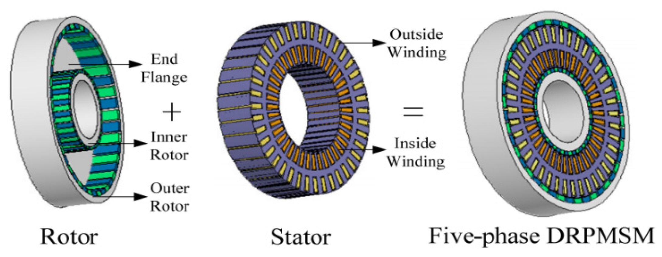
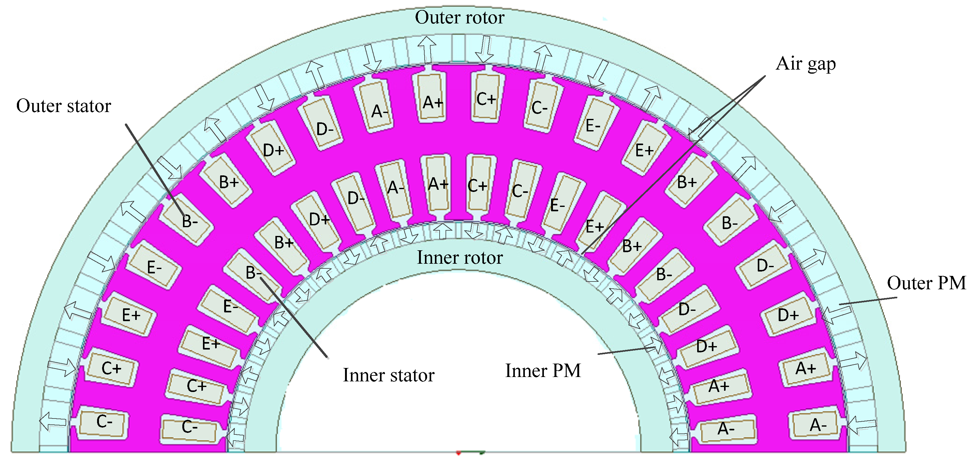
This paper investigates fault-tolerant operation of five-phase DRPMSM under all kinds of open-circuit fault conditions. As shown in
Figure 1, the five-phase DRPMSM consists of two rotors and one stator, which combines the advantages of high fault tolerance of multi-phase machines and high power density of dual rotors machines and permanent magnet machines. The motor can be seen as a combination of an “inner motor” and “outer motor”, of which the inner motor is composed of the inner rotor and the inside windings of the stator, and the outer motor is composed of the outer rotor and the outside windings of the stator [
11]. If inside and outside windings of the stator are connected in series, the motor can be driven by only a set of five-leg drivers, which is the machine’s series drive mode.
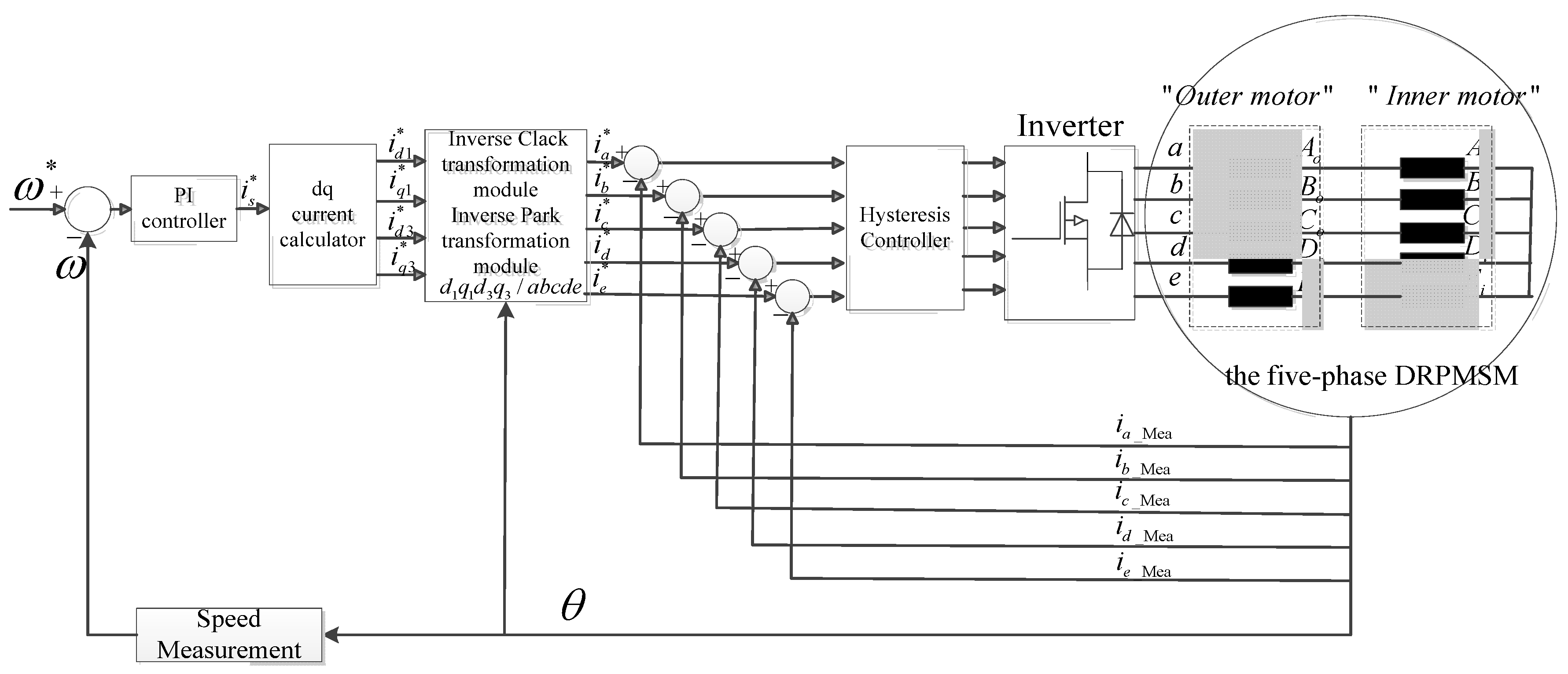
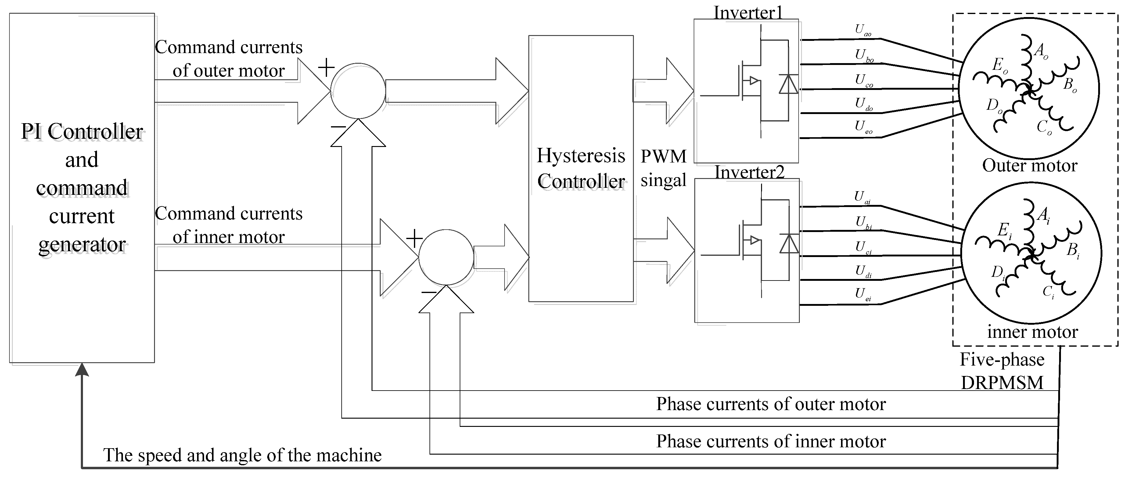
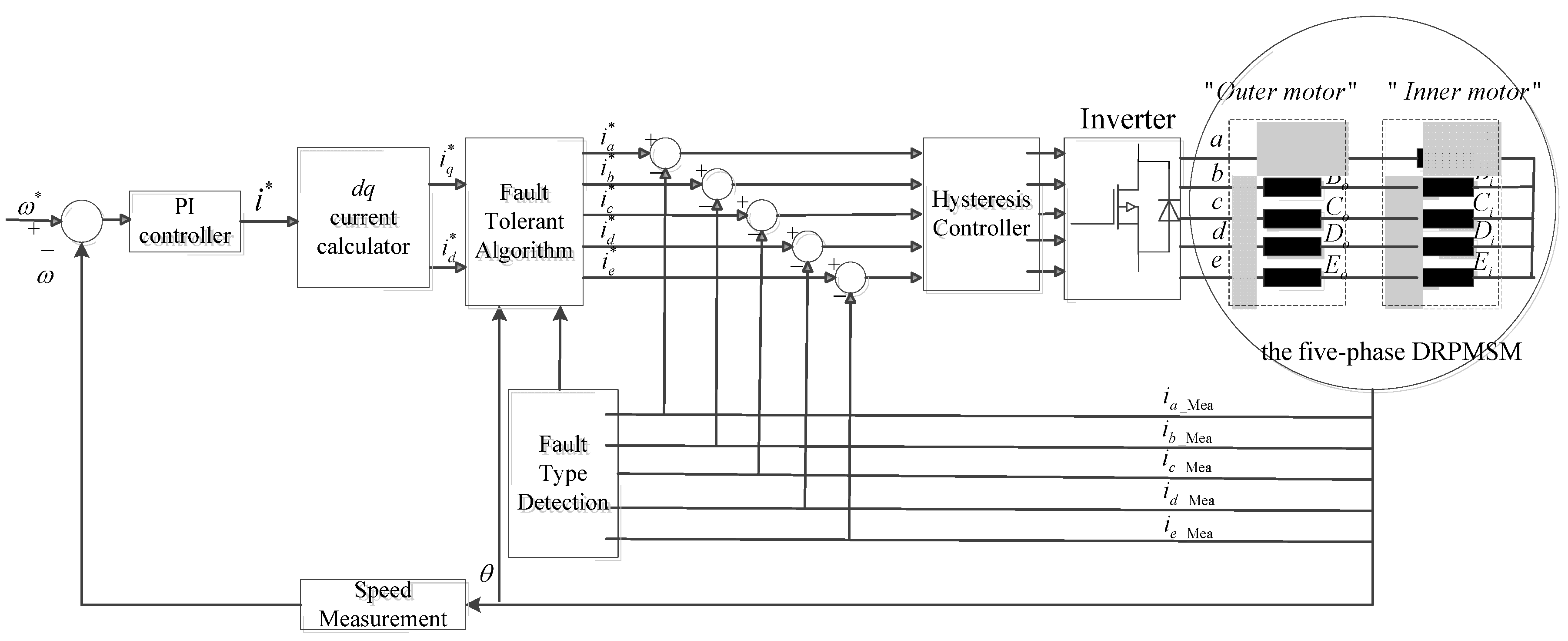
Figure 2 shows the control block diagram when the motor operates normally in series drive mode, in which fundamental current components and third harmonic current components are both considered. If the inside and outside windings of the stator are connected in parallel, two sets of five-leg drivers are needed and that is called the machine’s parallel drive mode.
Figure 1.
The component diagram of the five-phase dual-rotor permanent magnet synchronous motor (DRPMSM).
Figure 1.
The component diagram of the five-phase dual-rotor permanent magnet synchronous motor (DRPMSM).
Figure 2.
The control block diagram of five-phase DRPMSM in series drive mode under normal operation.
Figure 2.
The control block diagram of five-phase DRPMSM in series drive mode under normal operation.
The motor is fed by a five-phase voltage source inverter. Under normal conditions, the machine works steadily with a rated load. However, an unexpected fault in the drive system or machine may occur due to improper operation. According to statistics from [
12], the most common faults in the motor drive system are an open-phase or broken-phase of machines, short-circuiting of stator windings and damage to switching devices in the five-phase bridge inverter (damage to switching devices constitutes more than 50% of the motor applications’ system faults [
9]). As for the single line to ground short-circuit fault at the machine terminal or the switching devices short-circuit fault, by adopting Fast Fuse Technology (add fuse to the circuit in series), it can become an open-circuit fault [
12]. Therefore, research into open-circuit fault-tolerance of five-phase DRPMSM in different drive modes has universal significance. When a fault occurs in five-phase DRPMSM, the control system detects the type of fault and adopts the corresponding fault-tolerance operation technique, thus ensuring the machine’s ability to continue to operate under fault conditions.
For five-phase single-rotor PMSM fault-tolerance control strategies, much significant work has been done [
13,
14,
15,
16,
17,
18,
19,
20,
21,
22,
23,
24,
25,
26,
27,
28,
29,
30,
31,
32]. By injecting proper current in the remaining healthy phases under open-circuit fault conditions, the magnetomotive force (MMF) whose amplitude and rotational speed are the same as normal conditions can be generated [
14,
15]. However, this method cannot obtain the unique current solution, and there is larger torque ripple in the electromagnetic torque, and the total ohmic loss is not minimal either. For single-phase fault in five-phase PMSM, Dwari and Parsa [
16] eliminated the torque ripple in the electromagnetic torque and minimizes the total ohmic loss by using the theory of mirror symmetry of the currents in the heathy phases, but it cannot achieve maximum electromagnetic torque as the excitation currents are not equal in healthy phases. References [
17,
18,
19] maximize electromagnetic torque and eliminate the torque ripple under certain possible fault cases in five-phase PMSM by injecting excitation currents with a third-harmonic component. Dwari and Parsa [
20] studied possible fault cases and fault-tolerant operation of a five-phase brushless DC motor, whose back electromotive force (EMF) is a trapezoidal wave. Due to limitations of the drive circuit topology and stator windings of the machine in the aforementioned work, the sum of currents in healthy phases is constrained to zero. In [
21,
22], an additional bridge leg is added to the five-phase inverter to eliminate this constraint, and a smooth electromagnetic torque is obtained. References [
23,
24,
25,
26] discussed fault-tolerant operation under different stator winding configurations (pentacle, pentagon and star connection), and the result shows that the machine possesses higher fault-tolerance performance and smaller electromagnetic torque ripple when the stator winding is configured in a pentacle or pentagon. In [
27,
28], based on vectorial approach control and degrees of freedom, fault-operation of a seven-phase axial flux machine is investigated. In [
29,
30], a global fault-tolerance control technique is proposed, which can be applied to analyze all possible fault cases in any multi-phase motor regardless of the configuration of the motor’s stator windings. Mohammadpour
et al. [
31] proposed an iterative control strategy for
m-phase permanent machines under fault tolerant operation. Kestelyn and Semail [
32] proposes a novel way of generating optimal current references in real time to obtain a constant torque regardless of the number of open circuited phases in an
m-phase PMSM for practical applications. Previous works only concentrate on single rotor motors. As for five-phase DRPMSM, as there are two kinds of drive modes and the back EMFs of the inner motor and outer motor are different, previous work cannot be applied to five-phase DRPMSM directly, and also the interaction between the inner motor and outer motor under fault-tolerant conditions was not investigated in previous work.
In this paper, all possible open-circuit fault types of the five-phase DRPMSM in two drive modes (series drive mode and parallel drive mode) are analyzed. To ensure the five-phase DRPMSM achieves maximum electromagnetic torque with minimal torque-ripple under fault conditions, fault-tolerance techniques are adopted in this paper. Mirror symmetry of the currents in the heathy phases developed in [
16] and instantaneous power balance theory are applied to calculate the fault-tolerant injecting currents which contain the third harmonic component. The fault-tolerance performances in parallel drive mode and in series mode are compared. The analytical results are illustrated by finite element analysis (FEA) based on Maxwell. Finally, considering possible environmental factors, co-simulation based on Simulink-Simplorer-Maxwell is conducted.
2. The Open-Phase Fault Tolerance Technique of Five-Phase Dual-Rotor Permanent Magnet Synchronous Motor (DRPMSM) in Series Drive Mode
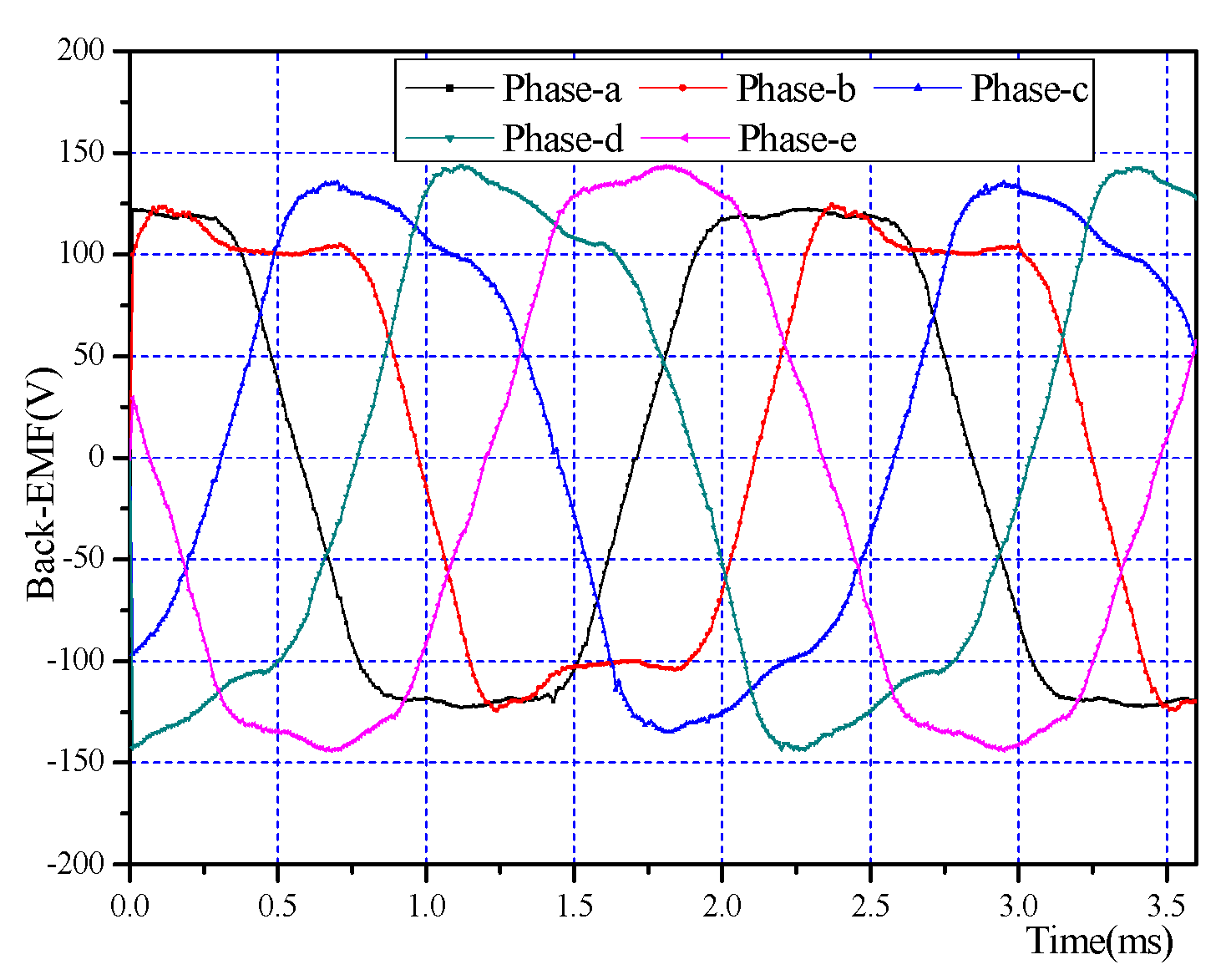
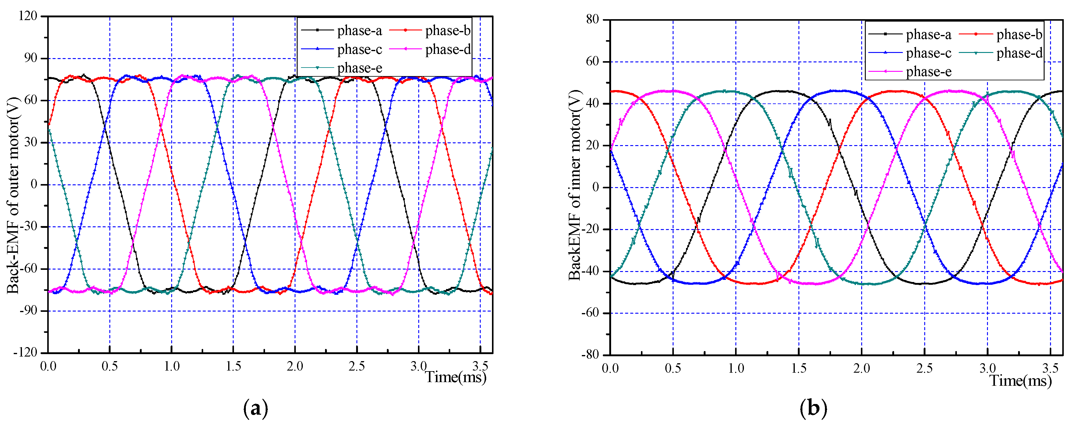
A 44 pole-40 plot five-phase DRPMSM with rated speed 1200 rpm and rated electromagnetic torque 18 Nm is designed in Maxwell. The back-EMF of the motor is a superposition of the inner motor and out motor. Operated at speed of 1200 rpm at no load, the motor’s back-EMF waveform and its harmonic component analysis are shown in
Figure 3. Using Fourier decomposition, fundamental and third harmonic components are only considered, and the back-EMF of the motor can be described as:
where,
is the fundamental amplitude of back-EMF,
is the third harmonic amplitude of back-EMF,
is electrical angular speed of the motor, and for this machine,
V and
V.
Figure 3.
The no-load back electromotive force (EMF) in series drive mode (a) waveform and (b) harmonic component analysis.
Figure 3.
The no-load back electromotive force (EMF) in series drive mode (a) waveform and (b) harmonic component analysis.
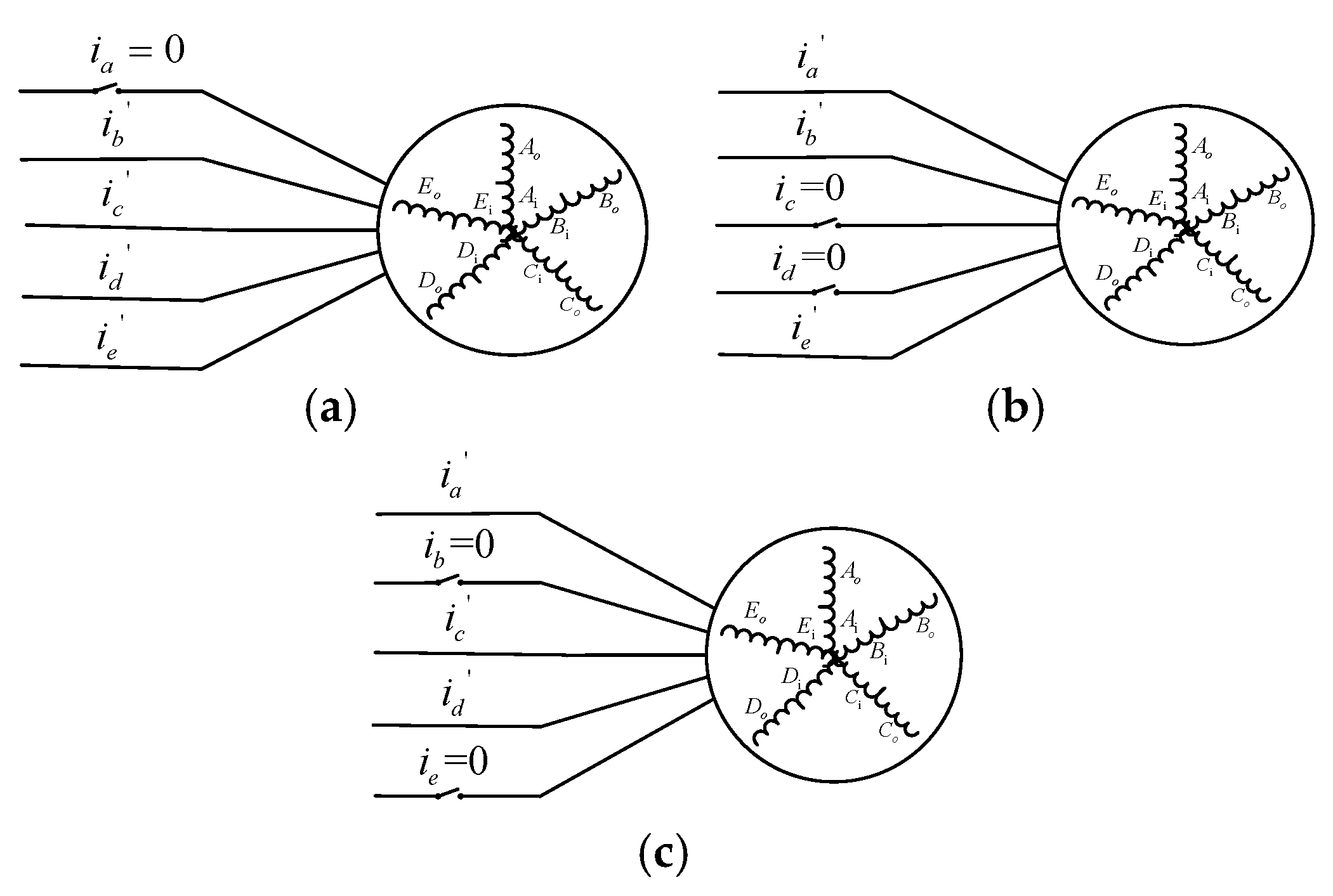
When the motor is operated in series drive mode, the currents passing inside windings and outside windings of stator are the same. In other words, any fault that occurs in the inverter or in the inside or outside windings of the stator will cause the corresponding phase to be totally open-circuit. Under normal conditions, the currents containing the third harmonic are injected to output maximum torque. Fundamental amplitude and third harmonic amplitude of injected current are
I1 = 6.36 A and
I3 =
E3/E1 ×
I1 = 1.03 A, respectively. When the motor operating in series mode, there are three types of fault that may occur, including single-phase open-circuit fault, nonadjacent double-phase fault and adjacent double-phase fault, as shown in
Figure 4.
Figure 4.
Three fault types when the motor operates in series drive mode. (a) Single-phase open-circuit fault; (b) adjacent double-phase fault; (c) nonadjacent double-phase fault.
Figure 4.
Three fault types when the motor operates in series drive mode. (a) Single-phase open-circuit fault; (b) adjacent double-phase fault; (c) nonadjacent double-phase fault.
2.1. Single-Phase Open-Circuit Fault-Tolerance Technique
Under single-phase open-circuit conditions, we assume phase “a” as the open phase. Using theory of mirror symmetry of the currents in the heathy phase, the injected currents can be expressed as:
in which,
is the rotor angular velocity,
,
and
,
are the amplitudes of the fundamental and third harmonic fault-tolerant current components,
,
and
,
are the initial phase angle of the fundamental and third harmonic fault-tolerant current components. There are eight unknown variables (
) in Equation (2), so eight equations are needed to solve these variables.
Firstly, the electrical input power and the mechanical output power should be balanced with neglecting loss, and then the following equation can be derived as:
where,
is average power produced by the fundamental components,
is average power produced by the third-harmonic components.
Secondly, due to the associated power electronic drive components and the thermal limits of stator winding, the maximum output torque is primarily decided by the maximum value of phase currents. However, under fault-tolerant conditions, in order to obtain the same output torque as in normal conditions with minimum fundamental components of fault-tolerant currents, the fundamental components of fault-tolerant currents should be constrained to be equal. The constraint for equal fundamental components can be defined as:
Thirdly, considering star connection of stator windings, the summation of currents in the heathy phases should be constrained to zero:
To satisfy Equation (5), the sum of different frequency components of currents should be zero. Therefore, Equation (5) can be derived as:
Fourthly, for torque-pulsation-free operation, taking advantage of extra freedoms of the equation in Equation (2), the torque ripple should be constrained to zero. When the fundamental and third-harmonic components of injected currents interact with the back-EMF, three different frequency components (2ω, 4ω, 6ω) are produced in the electromagnetic torque.
The condition for zero second-order torque pulsation can be obtained as:
The condition for zero fourth-order torque pulsation can be obtained as:
The condition for zero sixth-order torque pulsation can be obtained as:
Considering Equations (3) (4) (6)–(9), there are seven equations in total (in which Equation (6) contains two equations), thereby another constraint equation is needed in order to provide a unique solution. In this work, the total stator loss is minimized to find the last equation. Considering equal stator phase resistance, the equivalent cost function to minimize the loss can be defined as:
Setting Equation (10) as the objective function, combining with the previous equations, the Lagrange equation can be listed. With the known variables
E1,
E3 and
P defined at the beginning of this section, the unique optimum solution to the fault-tolerant currents can be obtained, as shown in
Table 1.
Table 1.
The optimum solutions to the fault-tolerant currents under single-phase open-circuit fault type.
Table 1.
The optimum solutions to the fault-tolerant currents under single-phase open-circuit fault type.
| The Unknown Variables | The Solution to the Equations | The Unknown Variables | The Solution to the Equations |
|---|
| 8.59 | | −43.88 |
| 1.11 | | −90 |
| 8.59 | | −136.22 |
| 0.69 | | −90 |
In order to generate the same average electromagnetic torque as under normal conditions, it can be calculated from
Table 1 that the maximum fundamental amplitude value 8.59 A in injected fault-tolerant currents is 1.35 times of the fundamental current amplitude value 6.36 A under normal conditions. For this solution, the third harmonic current components are not equal, but all of them have small amplitudes.
The torque results obtained by FEA are shown in
Figure 5. It can be observed that the average torque is 18.08 Nm with 2.3% torque ripple under normal conditions, whereas 14.41 Nm’s average torque with 30.4% torque ripple is produced under single phase open circuit fault conditions. As a comparison, under fault-tolerant conditions, the average torque is 17.43 Nm, which is 96.4% of the normal torque, and the torque ripple is 7.7%, which is much smaller than that under single phase open circuit fault conditions. The third harmonic components reduce the torque ripple, but this also causes a certain amount of copper loss. There are slight torque errors between fault-tolerant conditions and normal conditions.
Figure 5.
The motor operates under single phase open circuit conditions: (a) the electromagnetic torque obtained by finite element analysis (FEA); (b) the injected fault-tolerant currents.
Figure 5.
The motor operates under single phase open circuit conditions: (a) the electromagnetic torque obtained by finite element analysis (FEA); (b) the injected fault-tolerant currents.
However, the load back EMF, which is the back EMF when the motor operates at a speed of 1200 rpm with rated load, is used for FEA. The waveform of load back EMF is shown in
Figure 6, as we can see, due to the armature reaction, the load back EMF has changed a little in health phases compared to no-load back EMF in
Figure 3.
Figure 6.
The load back EMF waveform under single-phase open-circuit fault-tolerant conditions.
Figure 6.
The load back EMF waveform under single-phase open-circuit fault-tolerant conditions.
2.2. Non-Adjacent Double-Phase Open-Circuit Fault-Tolerance Technique
Under non-adjacent double-phase open-circuit fault-tolerant conditions, we assume phase “b” and “e” as open phases. The fault-tolerant currents in heathy phases can be expressed as:
There are six unknown variables to be determined. The condition for average mechanical and electrical power balance can be obtained as:
The same as the single-phase open-circuit fault in
Section 2.1, to maximize the motor’s electromagnetic torque, the fundamental components of the fault-tolerant currents can be constrained to be equal:
The condition for zero neutral current can be obtained as:
There are four Equations ((11)–(14)) that are defined at this point in this problem. Two more degrees of the freedom can be used to eliminate the second-order and forth-order torque pulsation of the machine. The condition for zero second-order torque pulsation is:
The condition for zero fourth-order torque pulsation is:
Considering the known variables (
,
), the solution to the fault-tolerant currents is obtained as shown in
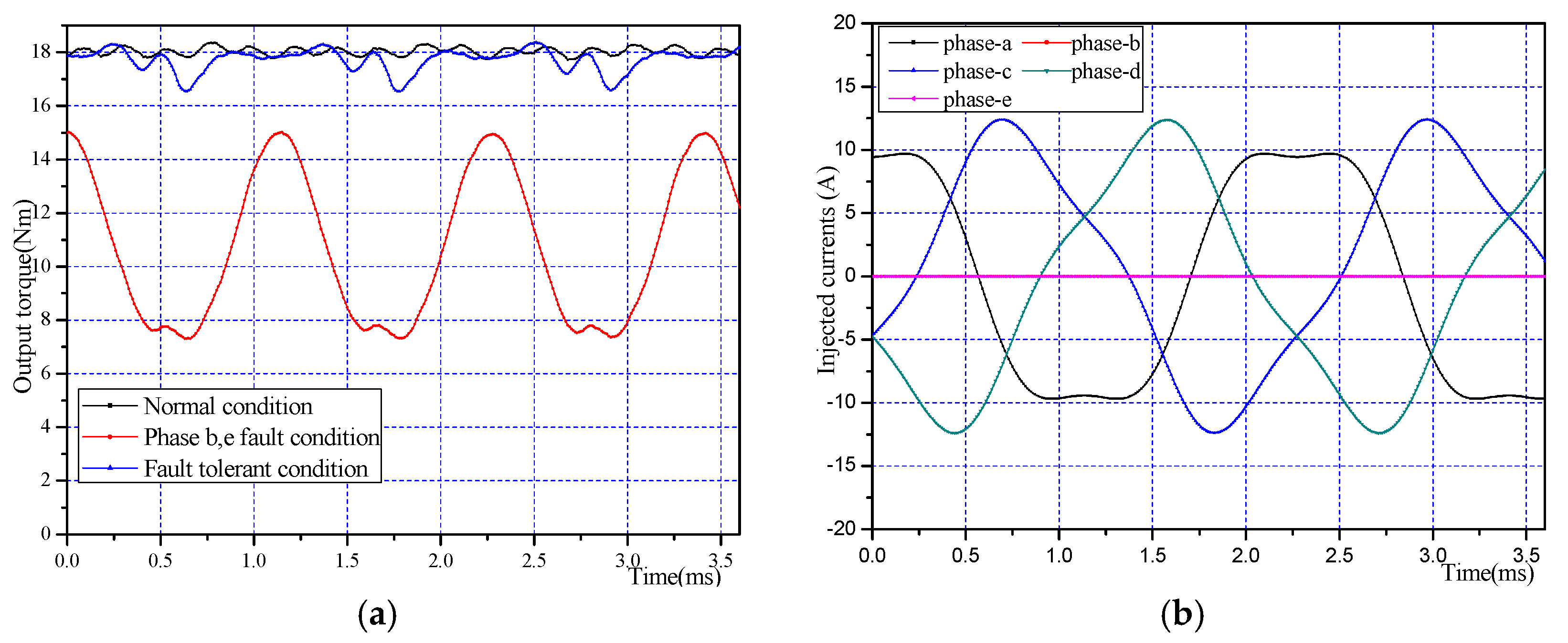
Table 2. In this solution, the average torque under the fault tolerant condition is equal to that under normal conditions. It can be calculated that the maximum fundamental amplitude value in injected fault-tolerant currents is 1.76 times the fundamental current amplitude value under normal conditions. The sixth-order torque pulsation in electromagnetic torque is not considered, and the additional degrees of freedoms are used to constrain the fundamental components of the fault-tolerant currents as equal. The torque and current results are shown in
Figure 7. Ninety-eight percent of the normal torque (17.71 Nm) with 10.4% ripple is produced when the motor operates under fault-tolerant conditions.
Table 2.
The optimum solutions to the fault-tolerant currents under non-adjacent double-phase open-circuit fault types.
Table 2.
The optimum solutions to the fault-tolerant currents under non-adjacent double-phase open-circuit fault types.
| The Unknown Variables | The Solution to the Equations | The Unknown Variables | The Solution to the Equations |
|---|
| 11.18 | | −120 |
| 11.18 | | 54.60 |
| −1.75 | - | - |
| 1.51 | - | - |
Figure 7.
The motor operates under non-adjacent double-phase open circuit conditions: (a) electromagnetic torque obtained by FEA; and (b) the injected fault-tolerant currents.
Figure 7.
The motor operates under non-adjacent double-phase open circuit conditions: (a) electromagnetic torque obtained by FEA; and (b) the injected fault-tolerant currents.
2.3. Adjacent Double-Phase Open-Circuit Fault-Tolerance Technique
Under adjacent double-phase open-circuit fault-tolerant conditions, we assume phase “c” and “d” as open phases. The fault-tolerant currents in heathy phases can be expressed as:
In order to solve the six variables () in Equation (11), the following equations can be listed.
The total average power produced by the healthy phases and output mechanical power can be related as:
The zero-neutral-current condition can be expressed as:
which can be further derived as:
Similar to the single-phase open-circuit conditions, the torque pulsation contains three different frequency components (2ω, 4ω, 6ω). The constraint for zero second-order torque pulsation can be expressed as
, which can be further derived as:
The condition for zero forth-order torque pulsation is:
The five equations of Equations (18)–(21) (Equation (19) contains two equations) are not enough to solve six variables. To reduce the maximum fundamental amplitude value of the injected currents, the additional freedom can be used to constrain the fundamental components as equal. Or, the additional freedom can be used to satisfy zero sixth-order torque pulsation. These two solutions are both solved and compared in this paper.
The condition for zero sixth-order torque pulsation is:
The constraint for equal fundamental components can be defined as:
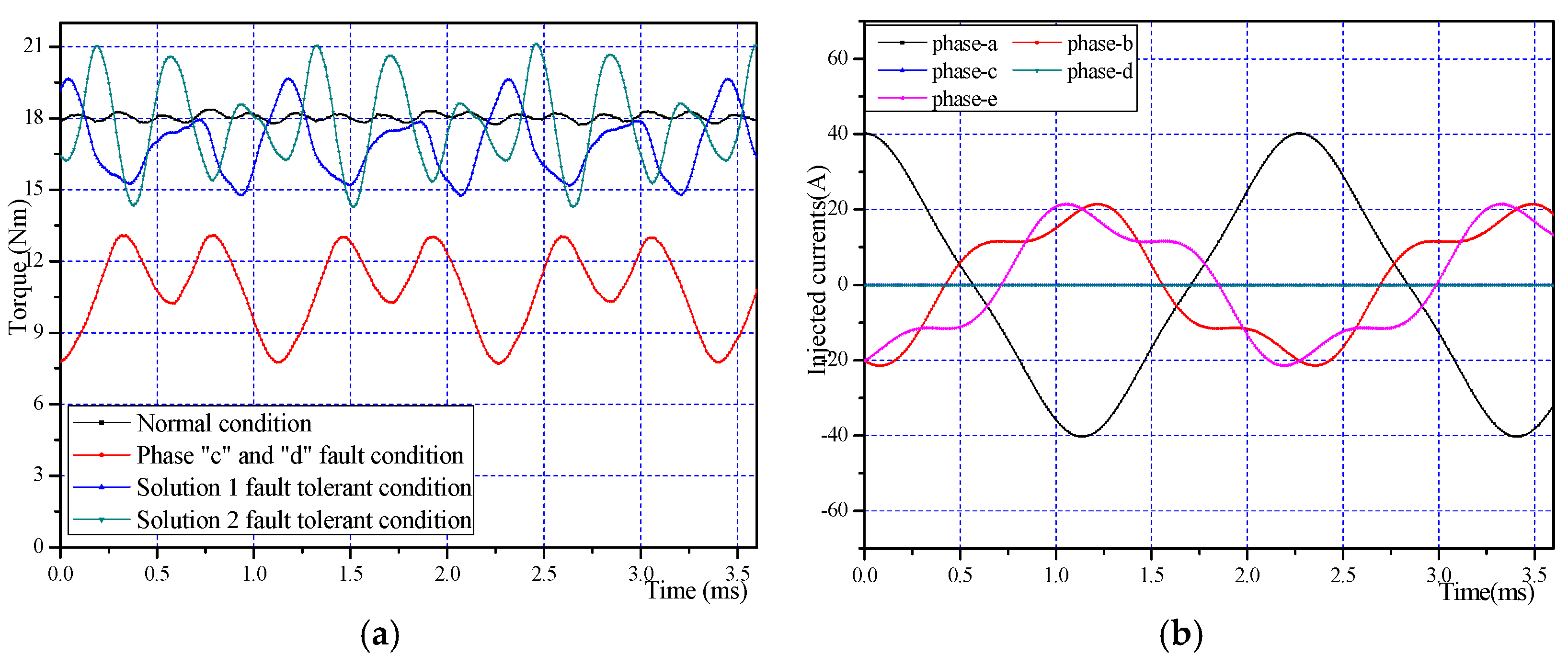
The solution 1 to the Equations (18)–(22) and solution 2 to the Equations (18)–(21),(23) are both shown in
Table 3. In these two solutions, the electromagnetic torque under fault tolerant conditions is equal to that under normal condition. It can be calculated that the maximum fundamental amplitude value in the injected fault-tolerant current is 5.82 times of the fundamental current amplitude value under normal conditions for solution 1, and that is 2.47 times for solution 2. However, the third harmonic component amplitude value is larger than the fundamental amplitude value in solution 2. The injected currents of these two solutions are both very large. Generally, the thermal limits of a stator phase winging or the associated power electronic drive components are decided according to the maximum root mean square (RMS) current allowable in the phase, so the injected current may be too large to maintain normal motor operation. In practical application, the electromagnetic torque can be reduced to obtain appropriate fault-tolerant current.
Table 3.
The optimum solutions to the fault-tolerant current under adjacent double-phase open-circuit fault type.
Table 3.
The optimum solutions to the fault-tolerant current under adjacent double-phase open-circuit fault type.
| The unknown variables | | | | | | |
| The solution 1 to the Equations (18)–(22) | 37.06 | −19.05 | 3.22 | 5.21 | 13.46 | 252.00 |
| The solution 2 to the Equations (18)–(21), (23) | 15.71 | 17.51 | 15.71 | 9.13 | 120 | 163.9 |
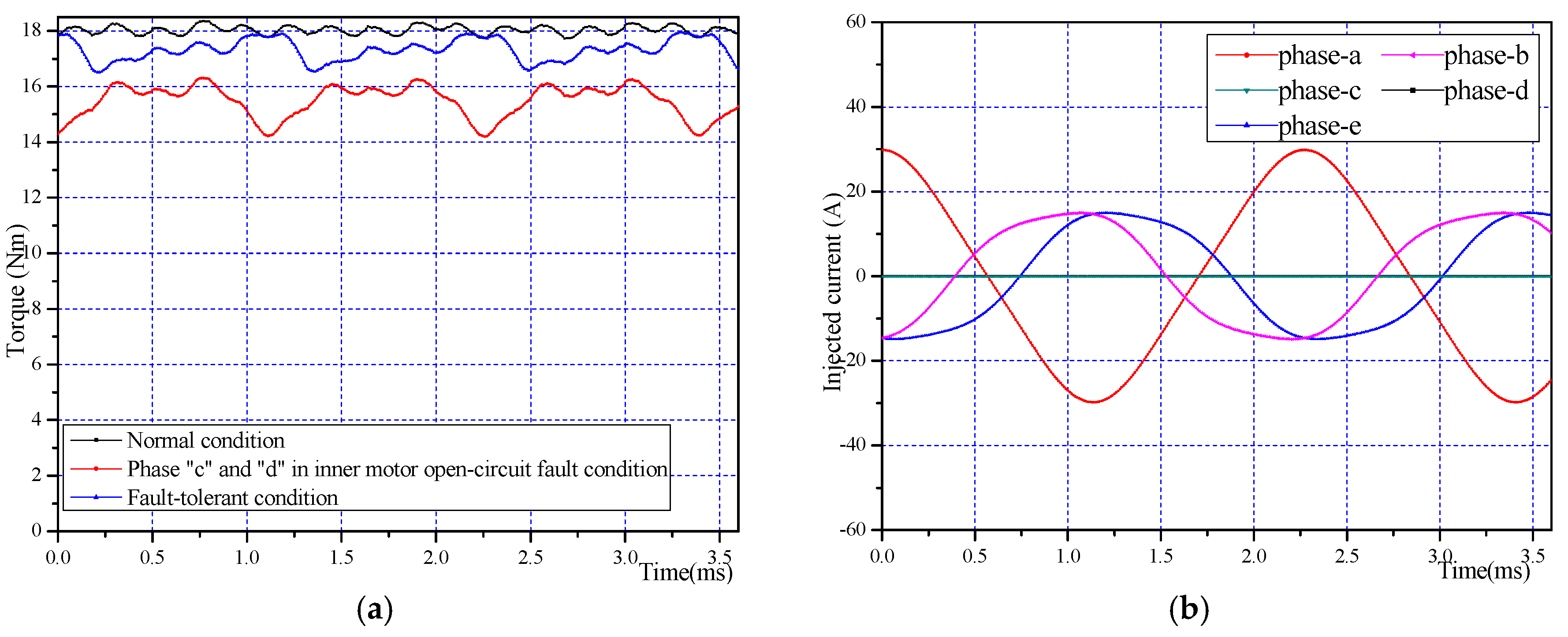
Figure 8a shows the torque obtained by FEA of this fault types. In total, 93.8% of the normal torque (16.95 Nm) with 28.9% ripple is produced for solution 1 under fault-tolerant conditions. Then, 94.1% of the normal torque (17.01 Nm) with 38.8% ripple is produced for solution 2. The torque ripple is larger in solution 2 than solution 1 because the sixth-order torque pulsation is not eliminated in solution 2. In this paper, solution 1 is adopted because the torque ripple is smaller.
Figure 8b shows the injected currents of solution 2. There is a slight error of average torque between fault-tolerant conditions and normal conditions, and this is because the load back-EMF changes a little compared to no-load back-EMF due to the armature reaction. It should be noted that this fault type is the most serious one in the series drive mode.
Figure 8.
The motor operates under adjacent double-phase open circuit conditions: (a) electromagnetic torque obtained by FEA; (b) the injected fault-tolerant currents of solution 2.
Figure 8.
The motor operates under adjacent double-phase open circuit conditions: (a) electromagnetic torque obtained by FEA; (b) the injected fault-tolerant currents of solution 2.
All possible open-circuit fault types in series drive mode have been investigated in this section. To make a better comparison,
Table 4 shows average torque and torque ripple under different fault types. Comparing to fault conditions, the average electromagnetic torque is enhanced largely and the torque ripple is significantly reduced under fault-tolerant conditions.
Table 4.
The produced average electromagnetic torque and torque-ripple under different fault types when machine operates in series driven mode.
Table 4.
The produced average electromagnetic torque and torque-ripple under different fault types when machine operates in series driven mode.
| Operates under Different Conditions | Average Electromagnetic Torque (Nm) | Torque Ripple (Percent) |
|---|
| Normal conditions | 18.08 | 2.3% |
| Single-phase open circuit fault conditions | 14.41 | 38.7% |
| Single-phase open circuit fault-tolerant conditions | 17.73 | 7.7% |
| Adjacent double-phase open circuit fault conditions | 10.75 | 49.9% |
| Adjacent double-phase open circuit fault-tolerant conditions | 16.95 | 28.9% |
| Non-adjacent double-phase open circuit fault conditions | 10.81 | 71.2% |
| Non-adjacent double-phase open circuit fault-tolerant conditions | 17.71 | 10.4% |
3. The Open-Phase Fault Tolerance Technique of Five-Phase DRPMSM in Parallel Drive Mode
When the machine operates in parallel drive mode, the inside stator windings and the outside stator windings of the five-phase DRPMSM are driven by two sets of inverters, respectively, as shown in
Figure 9. Outer motor and inner motor are fed by inverter 1 and inverter 2, respectively. One DC voltage source and two different levels of DC-DC converters are used to supply the DC-bus voltage of the two inverters. Unlike the machine operated in series mode, the open-circuit fault in stator windings of inner motor or outer motor only cause corresponding side faults. Therefore, the back EMF of the inner motor and outer motor must be considered separately.
Figure 10a shows the back EMF waveform of the inner motor and
Figure 10b shows the back EMF waveform of the outer motor.
Table 5 shows the data of back EMF and the injected currents that contain a third harmonic component under normal operation.
Figure 9.
The parallel drive model of the five-phase DRPMSM.
Figure 9.
The parallel drive model of the five-phase DRPMSM.
Table 5.
The details of the back-EMF and the injected currents when the motor operates at a speed of 1200 rpm at no load in parallel drive mode. DRPMSM: dual-rotor permanent magnet synchronous motor; Electromotive force: EMF.
Table 5.
The details of the back-EMF and the injected currents when the motor operates at a speed of 1200 rpm at no load in parallel drive mode. DRPMSM: dual-rotor permanent magnet synchronous motor; Electromotive force: EMF.
| Five-Phase DRPMSM | Inner Motor | Outer Motor |
|---|
| The fundamental amplitude of back EMF (V) | 50.50 | 90.61 |
| The third harmonic amplitude of back EMF (V) | −4.24 | −18.52 |
| The fundamental amplitude of injected currents (A) | 6.36 | 6.36 |
| The third harmonic amplitude of injected currents (A) | 0.53 | 1.30 |
| Average torque (Nm) | 6.47 | 11.61 |
Figure 10.
The back EMF waveform of (a) the outer motor and (b) the inner motor.
Figure 10.
The back EMF waveform of (a) the outer motor and (b) the inner motor.
From
Table 5, we can see the large difference of the third harmonic component between the inner motor and outer motor. The third harmonic content of back EMF is 8.4% in the inner motor whereas the content is 20% in the outer motor. Unlike the machine operated in series drive mode, the third harmonic content of injected currents can be controlled respectively in parallel mode.
There are a lot of fault types in parallel drive mode. Adopting the technique that injecting currents contain the third harmonic components, all possible fault types will be discussed in the following sections.
3.1. Single-Phase Open-Circuit Fault-Tolerance Technique
There are three types of faults in this fault situation: single-phase open-circuit in inner motor; single-phase open-circuit in outer motor; single-phase open-circuit in inner motor and outer motor.
3.1.1. Single-Phase Open-Circuit in Outer Motor
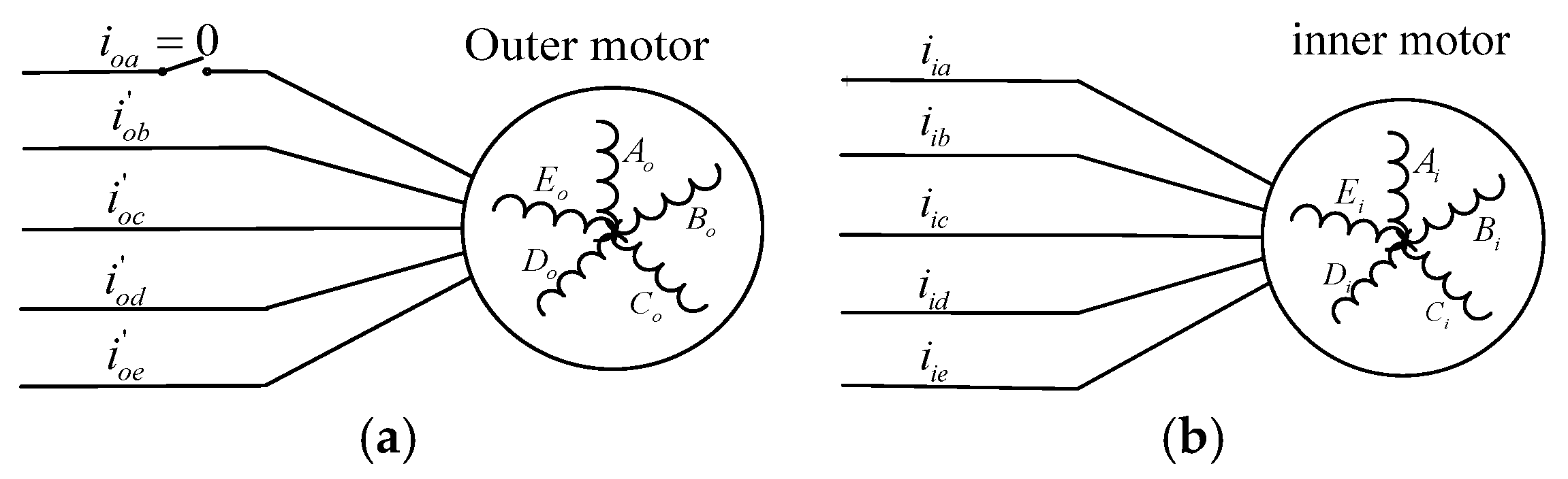
Under single-phase open-circuit in outer motor fault-tolerant conditions, we assume phase “a” in the outer motor as the open-circuit phase (as shown in
Figure 11).
Figure 11.
Single-phase open-circuit fault in the outer motor. (a) Outer motor; (b) inner motor.
Figure 11.
Single-phase open-circuit fault in the outer motor. (a) Outer motor; (b) inner motor.
The currents in the inner motor are unchanged. The injected currents in heathy phases of the outer motor can be expressed as:
According to the electromagnetic torque of the outer motor from
Table 5, considering the fundamental component and third harmonic component of the outer motor’s back EMF and adopting the fault-tolerant technique in
Section 2, the unknown variables can be solved, as shown in
Table 6. In this solution, the average torque under fault tolerant conditions is equal to that under normal conditions.
Table 6.
The optimum solutions to the fault-tolerant current under single-phase open-circuit fault type in outer motor.
Table 6.
The optimum solutions to the fault-tolerant current under single-phase open-circuit fault type in outer motor.
| The Unknown Variables | The Solution to the Equations | The Unknown Variables | The Solution to the Equations |
|---|
| 8.43 | | −45.67 |
| 1.37 | | −90 |
| 8.43 | | −134.34 |
| 0.84 | | −90 |
The maximum fundamental amplitude value in injected fault-tolerant currents is 1.32 times the fundamental current amplitude value under normal conditions. However, the current that passes the inner motor is normal, thus reducing the thermal of the stator.
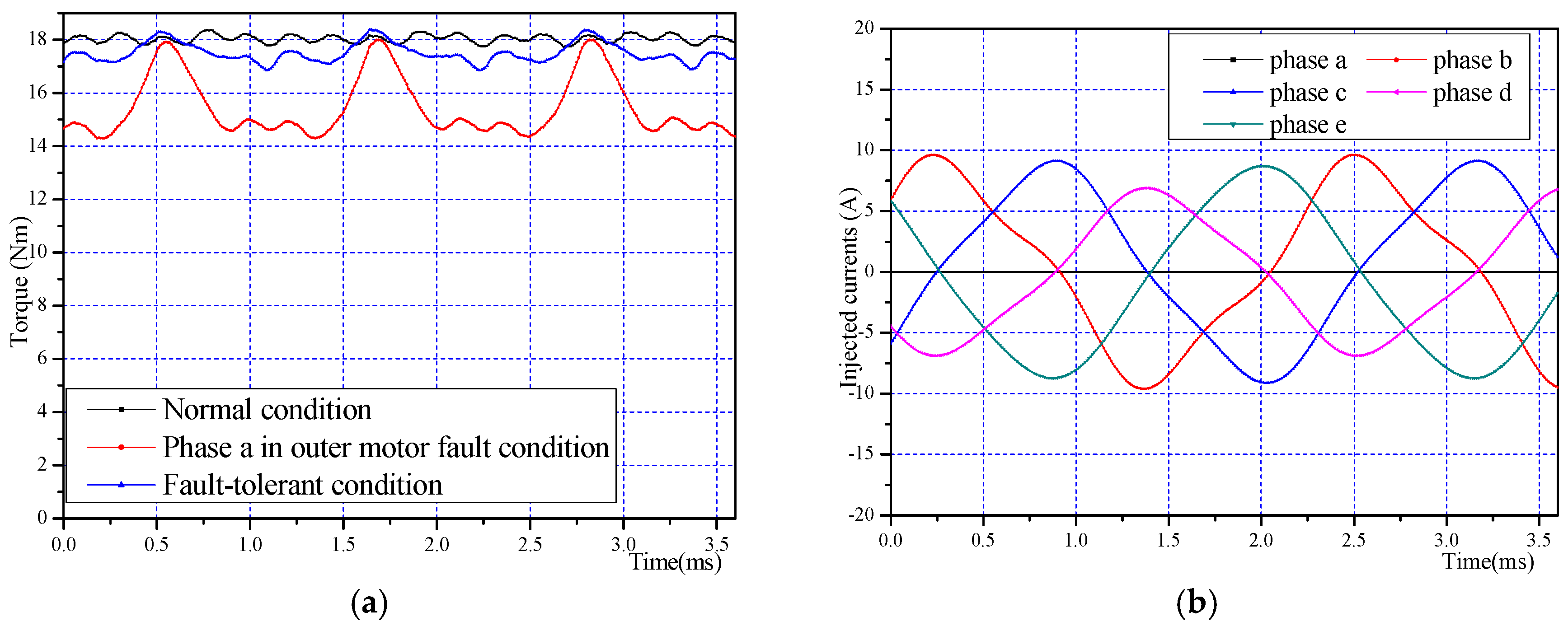
The torque and current results by FEA of this fault type are shown in
Figure 12. It can be observed that 15.46 Nm’s average torque with 23.9% ripple is produced under single phase open circuit fault in outer motor conditions. When the fault-tolerant currents are injected, the average torque is 17.50 Nm with 8.8% ripple, which is 97% of the normal torque, and the ripple is much smaller. When the outer motor operates under different conditions, the torque waveform of the inner motor is shown in
Figure 13.
Figure 12.
The motor operates under single-phase open circuit in outer motor conditions: (a) electromagnetic torque obtained by FEA; (b) the injected fault-tolerant currents of outer motor.
Figure 12.
The motor operates under single-phase open circuit in outer motor conditions: (a) electromagnetic torque obtained by FEA; (b) the injected fault-tolerant currents of outer motor.
The torque data of the inner motor and outer motor, respectively, are shown in
Table 7. From
Figure 13 and
Table 7, it can be seen that: when the outer motor is under normal conditions and under fault-tolerant conditions, the torques produced by the inner motor are almost same. It can be deduced that the outer motor can be controlled separately when faults occur in it.
Figure 13.
Torque waveform of the inner motor when the outer motor is working under different conditions.
Figure 13.
Torque waveform of the inner motor when the outer motor is working under different conditions.
Table 7.
The torque (Nm) produced by the inner motor under different conditions.
Table 7.
The torque (Nm) produced by the inner motor under different conditions.
| Different Working Situations of Outer Motor | Average Torque Produced by Inner Motor (Nm) | Torque Ripple of Inner Motor |
|---|
| Normal conditions | 6.61 | 5.8% |
| Single-phase open circuit fault in outer motor fault-tolerant conditions | 6.33 | 3.6% |
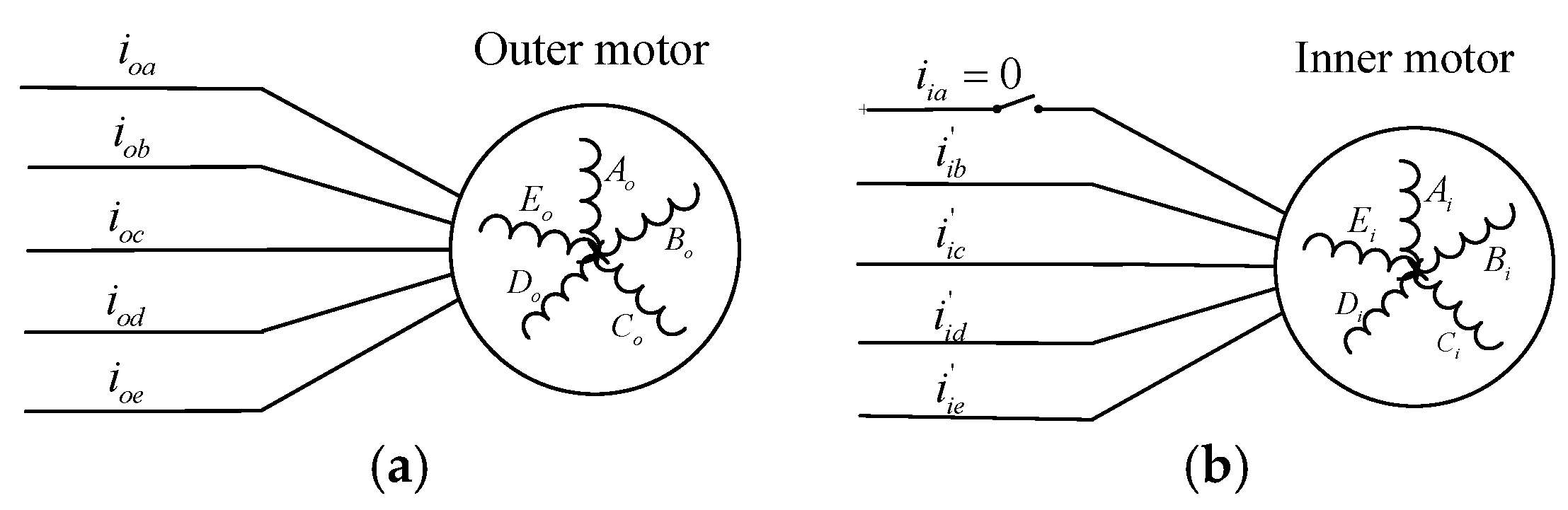
3.1.2. Single-Phase Open-Circuit in Inner Motor
Making the same assumptions as the single-phase open-circuit in the outer motor situation, phase “a” in inner motor is assumed as the fault phase (
Figure 14).
Figure 14.
Single-phase open-circuit in inner motor. (a) Outer motor; (b) inner motor.
Figure 14.
Single-phase open-circuit in inner motor. (a) Outer motor; (b) inner motor.
The same fault tolerant technique is adopted as single-phase open-circuit in the outer motor. Considering the fundamental component and third harmonic component of the outer motor’s back EMF, the unknown variables are solved as shown in
Table 8.
Table 8.
The optimum solutions to the fault-tolerant current under single-phase open-circuit fault type in inner motor.
Table 8.
The optimum solutions to the fault-tolerant current under single-phase open-circuit fault type in inner motor.
| The Unknown Variables | The Solution to the Equations | The Unknown Variables | The Solution to the Equations |
|---|
| 8.59 | | −40.33 |
| 0.60 | | −90 |
| 8.59 | | −139.67 |
| 0.37 | | −90 |
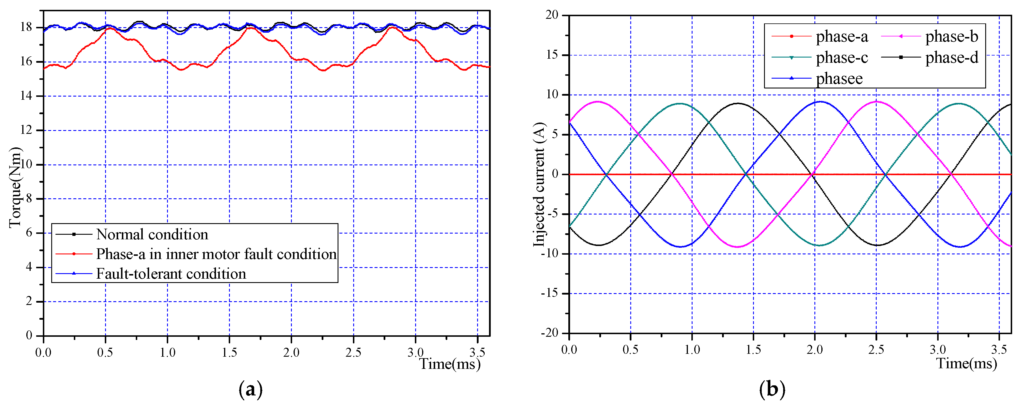
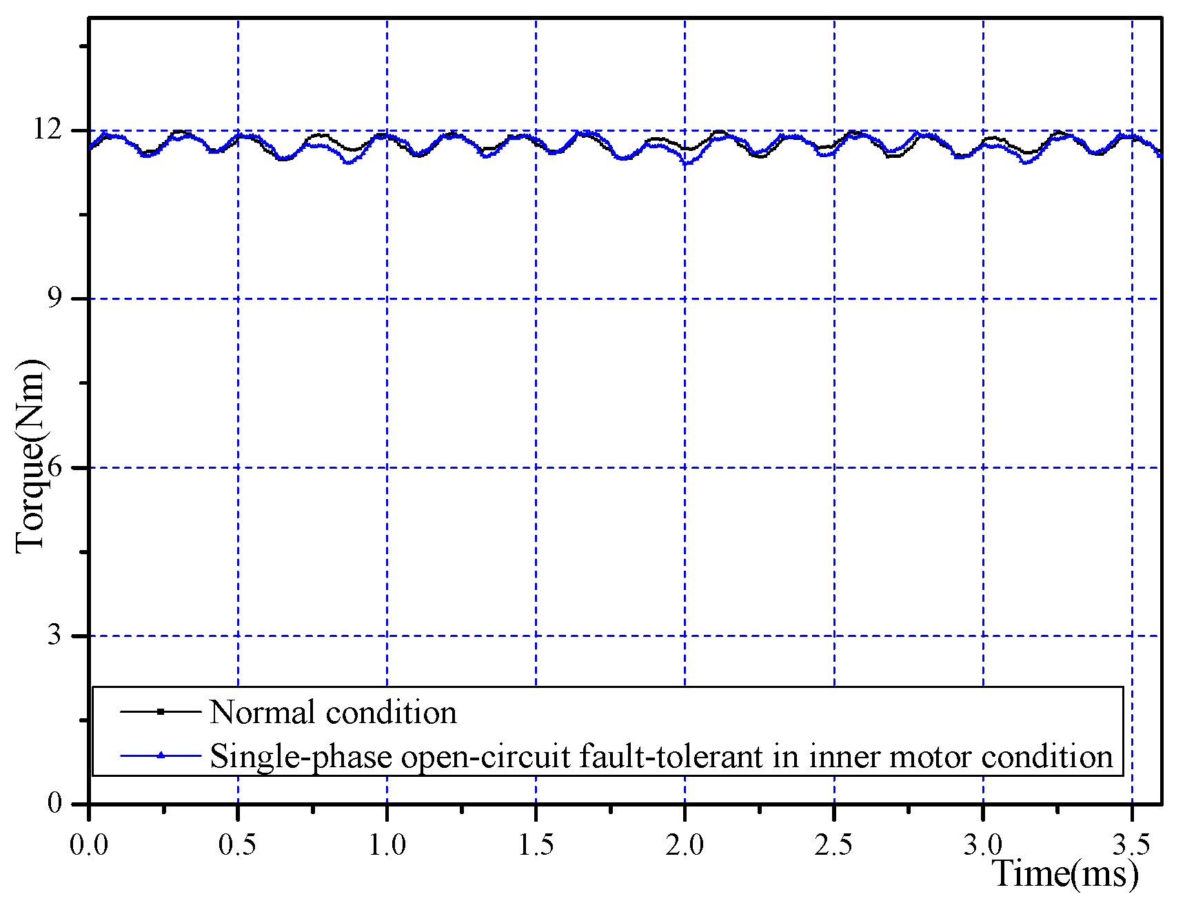
The maximum fundamental amplitude value in injected fault-tolerant currents is 1.35 times the fundamental current amplitude value under normal conditions. The FEA results of this fault type are shown in
Figure 15. It can be observed that 99.8% of the normal torque (18.00 Nm) with 4.0% ripple is produced under fault-tolerant conditions. Comparing to single-phase open circuit in the outer motor situation, the average electromagnetic torque is larger and the torque ripple is smaller. This is because the electromagnetic torque of the outer motor contributes more than the inner motor when the machine operates under normal conditions. Therefore, when fault occurs in the outer motor, the drop in torque is larger. When the inner motor operates under different conditions, the torque waveform of the outer motor is shown in
Figure 16.
The torque data of the inner motor and outer motor, respectively, are shown in
Table 9. From
Figure 16 and
Table 9, it can be seen the torque produced be the inner motor under this fault condition is almost the same as under normal conditions. An open-circuit fault in the outer motor has little impact on the torque characteristics of the outer motor. Thus, fault-tolerant control is independent for inner and outer motors.
Table 9.
The torque (Nm) produced by outer motor under different conditions.
Table 9.
The torque (Nm) produced by outer motor under different conditions.
| Different Working Situations of Inner Motor | Average Torque Produced by Outer Motor (Nm) | Torque Ripple of Outer Motor |
|---|
| Normal conditions | 11.76 | 4.4% |
| Single-phase open circuit fault in inner motor fault-tolerant conditions | 11.73 | 4.7% |
Figure 15.
The motor operates under single-phase open circuit in the inner motor condition: (a) electromagnetic torque obtained by FEA; (b) the injected fault-tolerant currents of the inner motor.
Figure 15.
The motor operates under single-phase open circuit in the inner motor condition: (a) electromagnetic torque obtained by FEA; (b) the injected fault-tolerant currents of the inner motor.
Figure 16.
Torque waveform of outer motor when inner motor is working under different conditions.
Figure 16.
Torque waveform of outer motor when inner motor is working under different conditions.
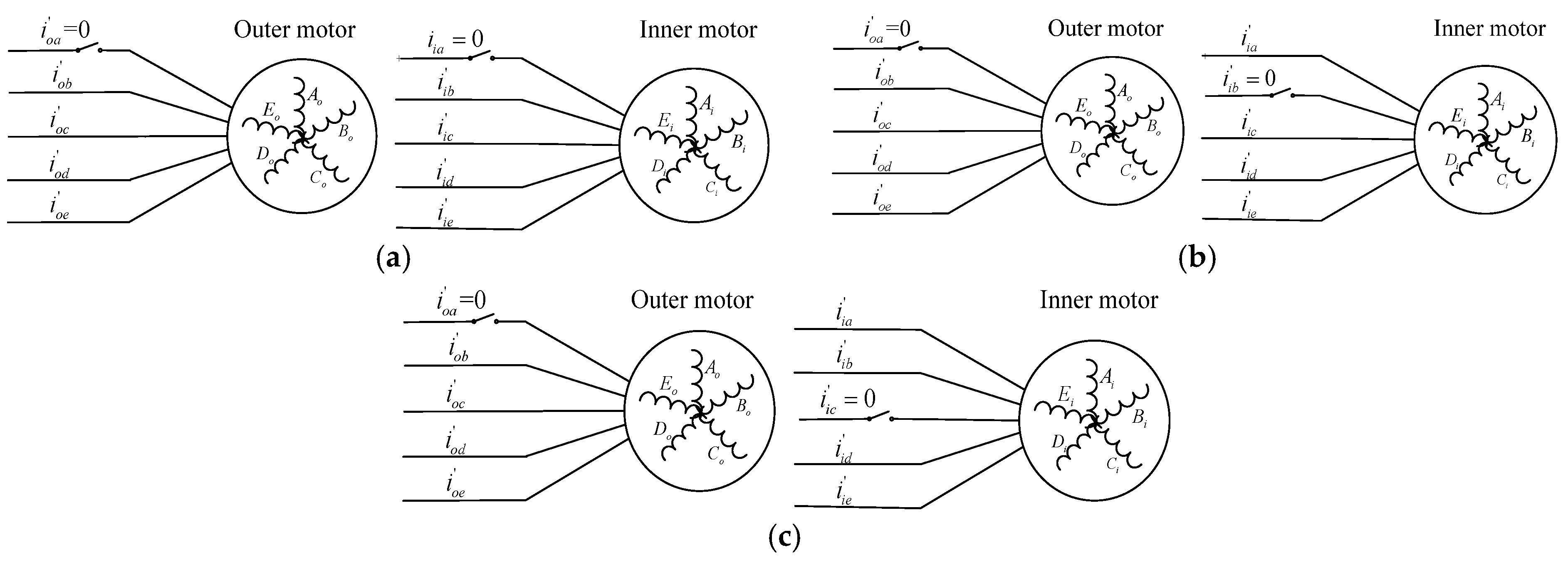
3.1.3. Single-Phase Open-Circuit in Both Inner Motor and Outer Motor
The open-circuit fault-tolerance of different phases in the inner motor (or in outer motor) leads to different torque ripple characteristics. On the other hand, the total torque is a superposition of inner motor torque and outer motor torque. So, when torque of the inner motor and outer motor with different torque ripple characteristics is superposed, the torque ripples are different in terms of produced torque. So, for this fault type, there are three different fault cases: the same phase in inner motor and out motor are open open-circuit phases (
Figure 17a: assume phase “a” in outer motor and in inner motor are open phases); “adjacent phase” in inner motor and out motor are open open-circuit phases (
Figure 17b: assume phase “a” in outer motor and phase b in inner motor are open phases); “non-adjacent phase” in inner motor and out motor are open open-circuit phases (
Figure 17c: assume phase “a” in outer motor and phase “c” in inner motor are open phases).
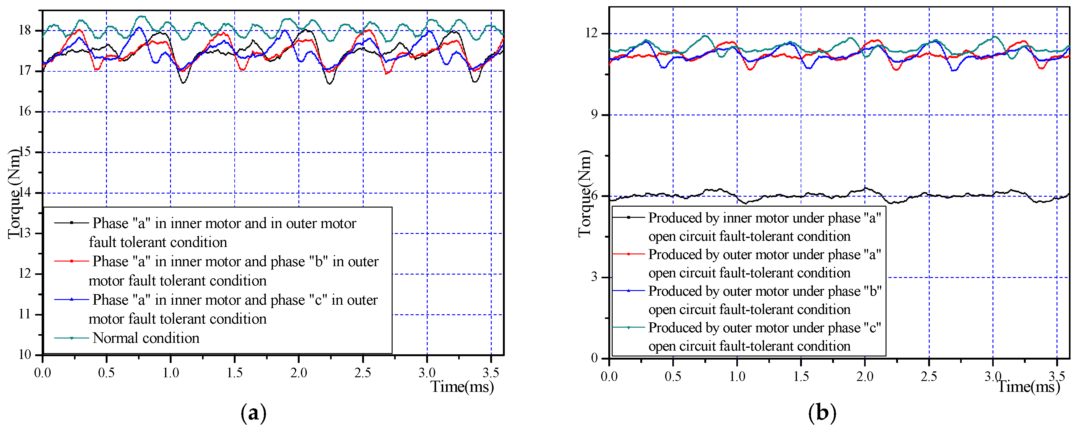
For three fault cases of this type, the torques obtained by FEA are shown in
Figure 18a). The injected currents are a combination of the above two fault types (
Section 3.1.1 &
Section 3.1.2). The torque details of these three fault cases are shown in
Table 10. From
Figure 18a and
Table 10, it can be seen the average torque of these three fault situations is almost equal while the differences in torque ripples are larger.
Figure 18b shows the torque waveform by the inner motor and outer motor, respectively, under different fault cases of this fault type. The torque ripple is smaller under fault case b and case c, and this is because the torque-ripple produced by the inner motor and outer motor has the effect of offsetting each other as seen from
Figure 18b.
Figure 17.
Single-phase open-circuit fault types in both inner motor and outer motor. (a) Same phase in inner motor and out motor are open open-circuit; (b) “adjacent phase” in inner motor and out motor are open open-circuit; (c) “non-adjacent phase” in inner motor and out motor are open open-circuit.
Figure 18.
The motor operates under single-phase open-circuit in both inner motor and outer motor conditions: (a) electromagnetic torque obtained by FEA; (b) the torque produced by outer motor and inner motor, respectively.
Figure 18.
The motor operates under single-phase open-circuit in both inner motor and outer motor conditions: (a) electromagnetic torque obtained by FEA; (b) the torque produced by outer motor and inner motor, respectively.
Table 10.
The details of electromagnetic torque of the three fault cases under single-phase open-circuit in both inner motor and outer motor fault types.
Table 10.
The details of electromagnetic torque of the three fault cases under single-phase open-circuit in both inner motor and outer motor fault types.
| Fault Situations | Average Electromagnetic Torque (Nm) | Torque Ripple (Percent) |
|---|
| Case a: same phase in inner motor and out motor are open open-circuit phases | 17.46 | 7.7% |
| Case b: “adjacent phase” in inner motor and out motor are open open-circuit phases | 17.46 | 6.2% |
| Case c: “non-adjacent phase” in inner motor and out motor are open open-circuit phases | 17.46 | 6.0% |
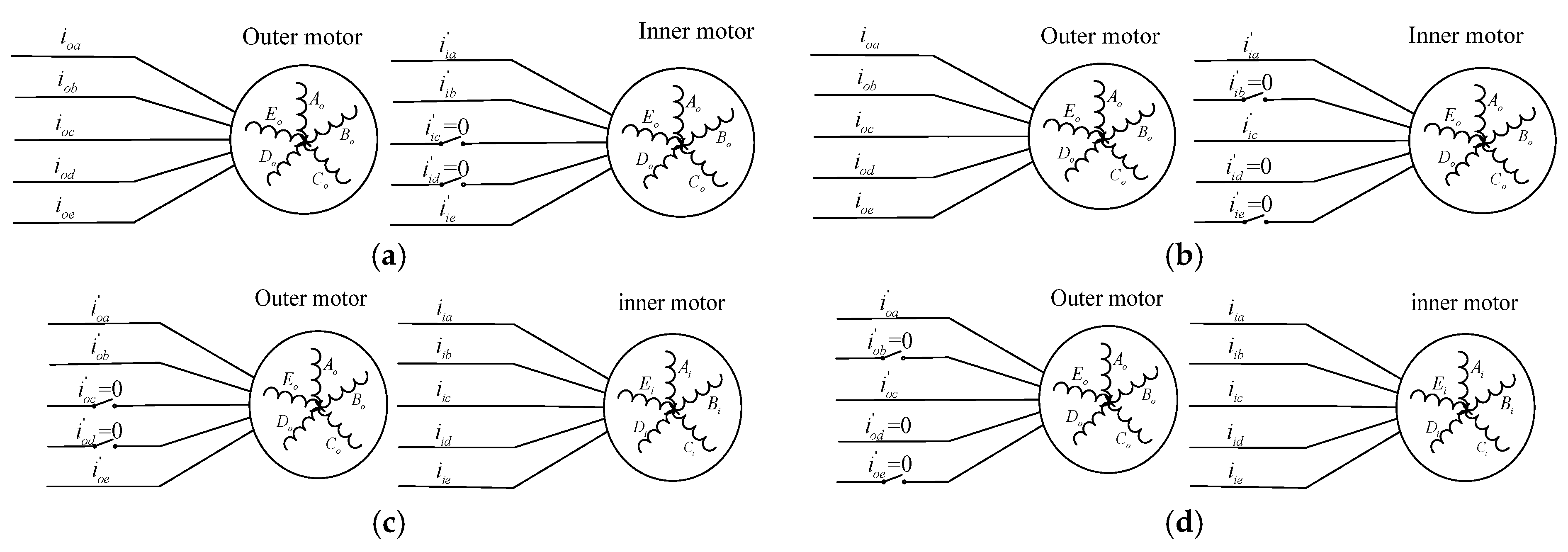
3.2. Double-Phase Open-Circuit in One Side of Motor while the Other Side of the Motor Operates Normally Fault-Tolerance Technique
There are four fault types in this fault situation (as shown in
Figure 19): (I) Adjacent double-phase open-circuit in the inner motor while the outer motor operates normally (
Figure 19a); (II) Non-adjacent double-phase open-circuit in the inner motor while the outer motor operates normally (
Figure 19b); (III) Adjacent double-phase open-circuit in the outer motor while the inner motor operates normally (
Figure 19c); (IV) Non-adjacent double-phase open-circuit in the outer motor while the inner motor operates normally (
Figure 19d).
Figure 19.
Four types of fault (double-phase open-circuit in one side motor while the other side motor operates normally). (a) Adjacent double-phase open-circuit in the inner motor; (b) non-adjacent double-phase open-circuit in the inner motor; (c) adjacent double-phase open-circuit in the outer motor; (d) non-adjacent double-phase open-circuit in the outer motor.
3.2.1. Adjacent Double-Phase Open-Circuit in the Inner Motor While the Outer Motor Operates Normally
Without loss of generality, phase “c” and “d” in the inner motor are assumed as open phases. Adopting the adjacent double-phase fault-tolerant technique discussed under series driven mode, considering the back EMF of inner motor, the injected fault-tolerant currents can be expressed as:
in which,
is electrical angular velocity of the machine. From Equation (25), it can be seen that the maximum fundamental amplitude value in injected fault-tolerant currents is 4.47 times of the fundamental current amplitude value under normal conditions.
The FEA results are shown in
Figure 20. It can be observed that 15.47 Nm’s average torque with 12.2% ripple is produced under adjacent double phases open circuit fault in the outer motor condition. When the fault-tolerant currents are injected, the average torque is 17.32 Nm with 8.5% ripple, which is 95.8% of the normal torque, and the ripple is much smaller.
Figure 20.
The motor operates under adjacent double-phase open circuit in inner motor condition: (a) electromagnetic torque obtained by FEA; (b) the injected currents of inner motor.
Figure 20.
The motor operates under adjacent double-phase open circuit in inner motor condition: (a) electromagnetic torque obtained by FEA; (b) the injected currents of inner motor.
3.2.2. Non-Adjacent Double-Phase Open-Circuit in the Inner Motor while the Outer Motor Operates Normally
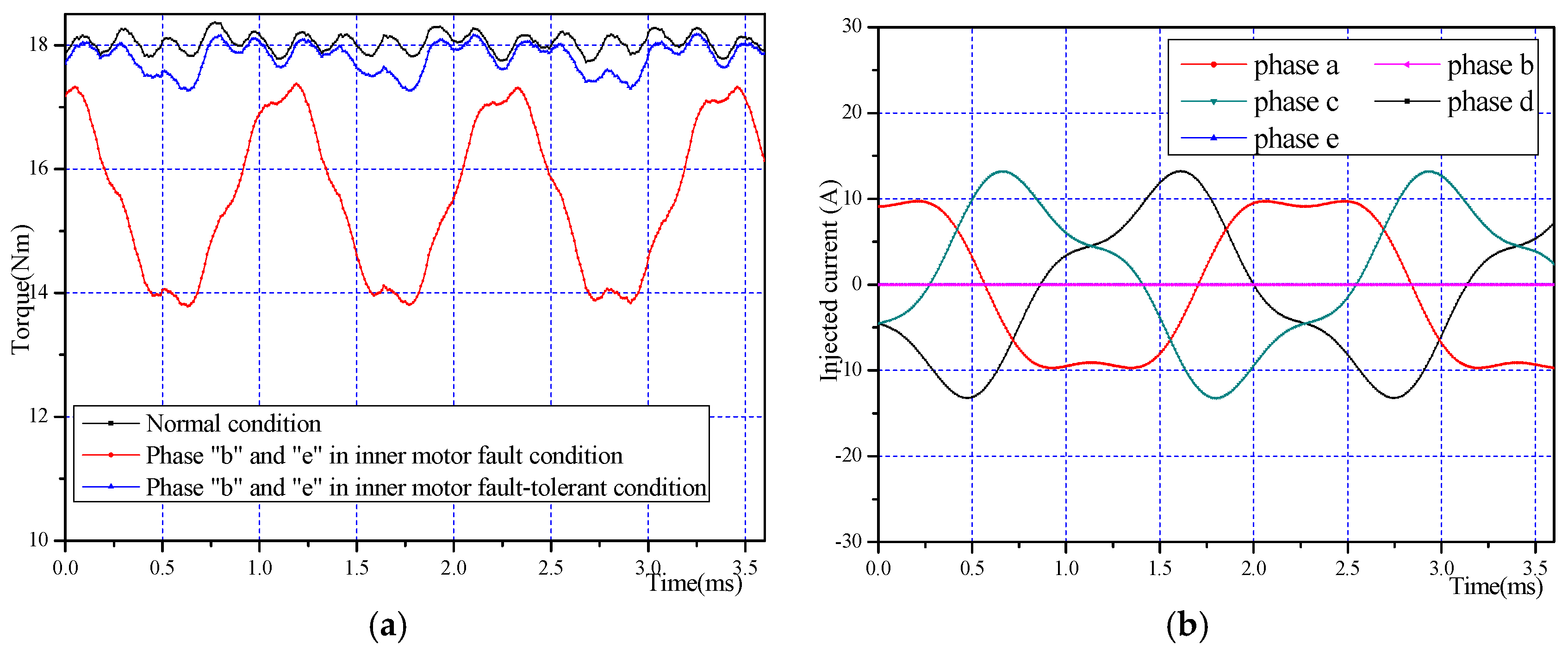
Without loss of generality, phases “b” and “e” in the inner motor are assumed as open phases. Adopting the non-adjacent double-phase fault-tolerant technique discussed in the series drive mode, the injected fault-tolerant currents can be expressed as:
Figure 21 shows the electromagnetic torque obtained by FEA. 17.79 Nm’s average torque with 5.1% ripple is produced under fault tolerant conditions. The torque ripples mainly come from the uncompensated six-order pulsating power component. The additional degrees of freedom are used to reduce the maximum fundamental amplitude value of the fault-tolerant current.
Figure 21.
The motor operates under non-adjacent double-phase open circuit in inner motor condition: (a) electromagnetic torque obtained by FEA; (b) the injected currents of inner motor.
Figure 21.
The motor operates under non-adjacent double-phase open circuit in inner motor condition: (a) electromagnetic torque obtained by FEA; (b) the injected currents of inner motor.
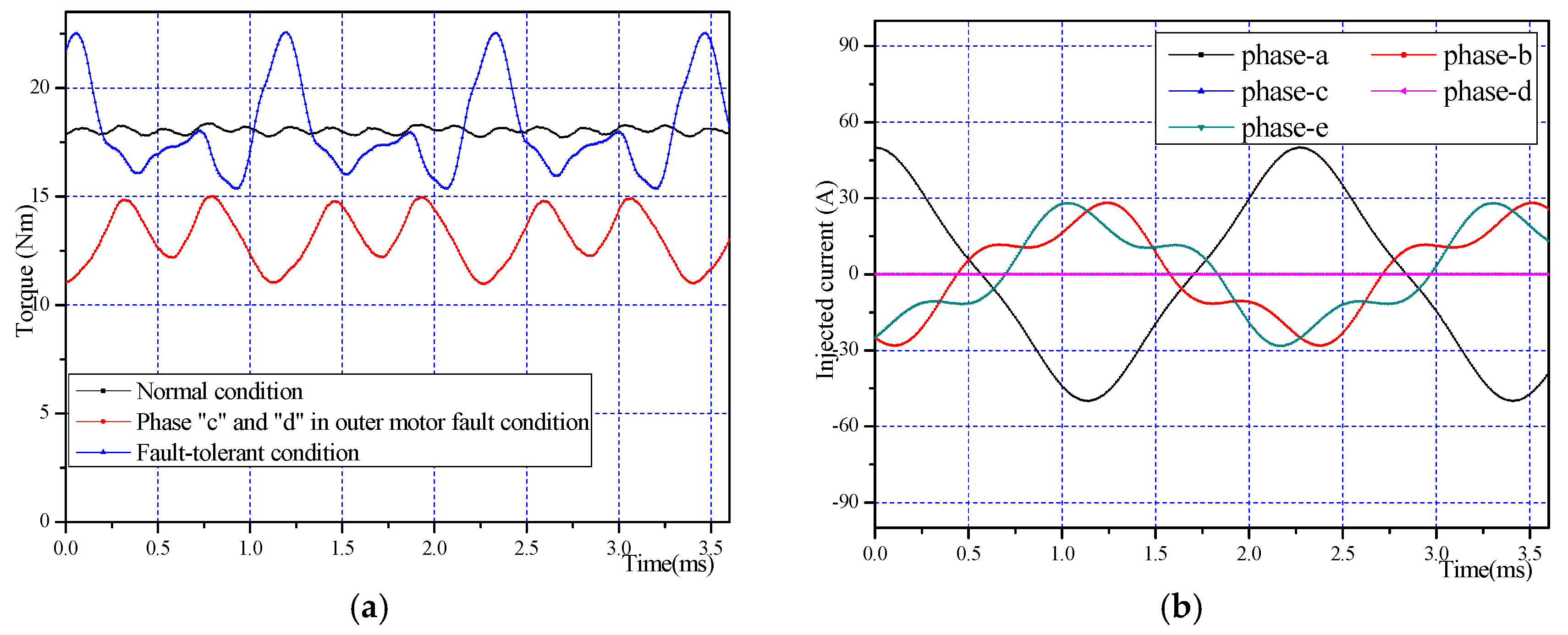
3.2.3. Adjacent Double-Phase Open-Circuit in Outer Motor while Inner Motor Operates Normally
Without loss of generality, phase “c” and “d” in outer motor are assumed as open phases. Adopting adjacent double-phase fault-tolerant technique discussed in series drive mode, the injected fault-tolerant currents can be expressed as:
Figure 22 shows the electromagnetic torque obtained by FEA, from which it can be seen that an average torque of 17.68 Nm with 21% ripple is produced under fault-tolerant conditions. Comparing adjacent double-phase fault in the inner motor, the same type of fault that occurs in the outer motor is more severe. It is because the outer motor contributes more when the motor operates under normal conditions.
Figure 22.
The motor operates under adjacent double-phase open circuit in the outer motor condition: (a) electromagnetic torque obtained by FEA; (b) the injected currents of the outer motor.
Figure 22.
The motor operates under adjacent double-phase open circuit in the outer motor condition: (a) electromagnetic torque obtained by FEA; (b) the injected currents of the outer motor.
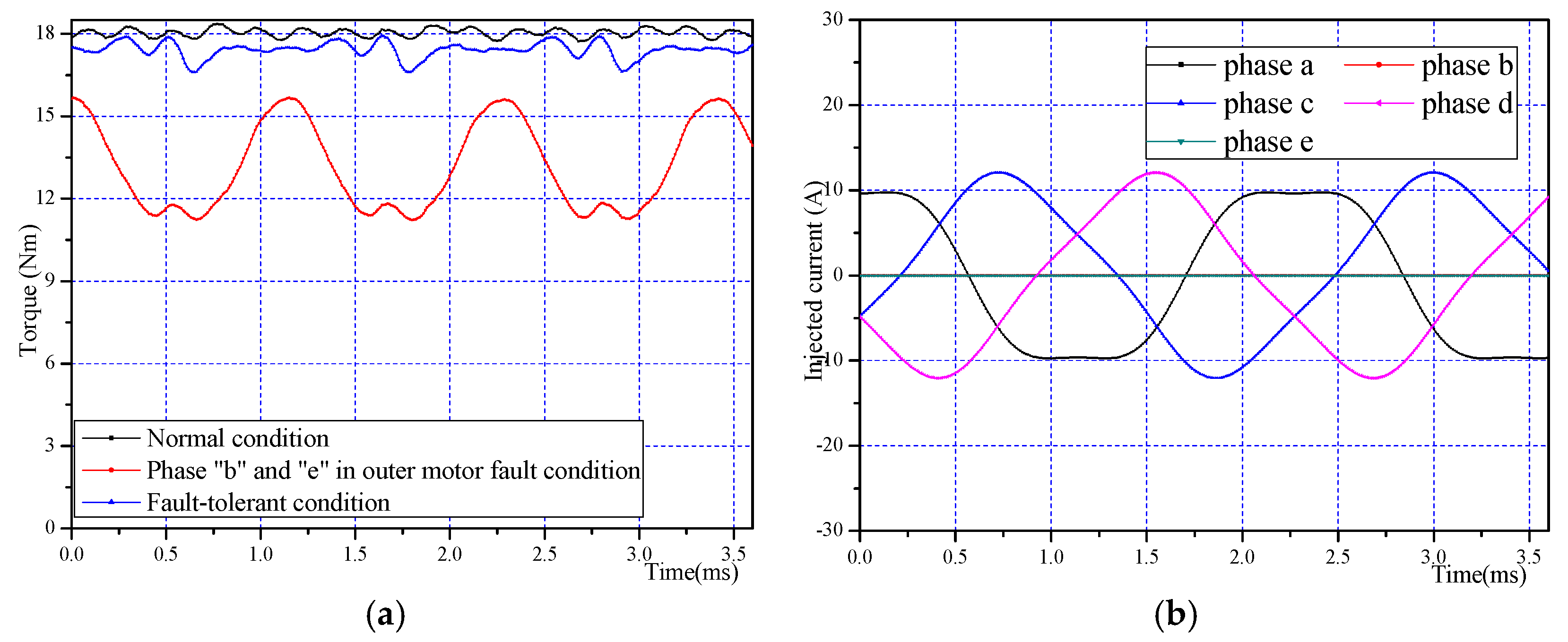
3.2.4. Non-Adjacent Double-Phase Open-Circuit in the Outer Motor while the Inner Motor Operates Normally
Without loss of generality, phases “b” and “e” in the outer motor are assumed to be open phases. Adopting the non-adjacent double-phase fault-tolerant technique discussed in the series driven mode, the injected fault-tolerant currents can be expressed as:
Figure 23 shows the FEA results of this type, from which it can be seen that an average torque of 17.41 Nm with 7.7% ripple is produced under fault-tolerant conditions. It is the same situation for the non-adjacent double-phase open-circuit in the inner motor, whereby the torque ripple comes from the uncompensated six-order pulsating power component and additional degrees of freedom are used to reduce the fault-tolerant current.
Figure 23.
The motor operates under non-adjacent double-phase open circuit in outer motor conditions: (a) electromagnetic torque obtained by FEA; (b) the injected currents of the outer motor.
Figure 23.
The motor operates under non-adjacent double-phase open circuit in outer motor conditions: (a) electromagnetic torque obtained by FEA; (b) the injected currents of the outer motor.
Torque details (average torque, torque ripple
etc.) of these fault types in
Section 3.2 are shown in
Table 11. The torque ripple is much smaller when fault-tolerant techniques are adopted. Faults in the outer motor are much worse compared to the inner motor because the outer motor contributes more torque to the total torque. The same as in series drive mode, the adjacent double phase fault is the most severe fault type.
Table 11.
The details of average electromagnetic torque and torque-ripple under double phase open circuit fault in one side of motor when machine operates in the parallel driven mode.
Table 11.
The details of average electromagnetic torque and torque-ripple under double phase open circuit fault in one side of motor when machine operates in the parallel driven mode.
| Operates under Different Conditions | Average Electromagnetic Torque (Nm) | Torque Ripple (Percent) |
|---|
| Adjacent double phase open circuit fault in inner motor | 15.47 | 12.2% |
| Adjacent double phase open circuit fault tolerance in inner motor | 17.32 | 8.5% |
| Non-adjacent double phase open circuit fault in inner motor | 15.63 | 21.3% |
| Non-adjacent double phase open circuit fault tolerance in inner motor | 17.79 | 5.1% |
| Adjacent double phase open circuit fault in outer motor | 13.05 | 30.9% |
| Adjacent double phase open circuit fault tolerance in outer motor | 17.68 | 21% |
| Non-adjacent double phase open circuit fault in outer motor | 13.43 | 33.1% |
| Non-adjacent double phase open circuit fault tolerance in outer motor | 17.41 | 7.7% |
3.3. Double-Phase Open-Circuit in One Side of Motor with Single-Phase Open-Circuit in the Other Side of Motor Fault-Tolerance Technique
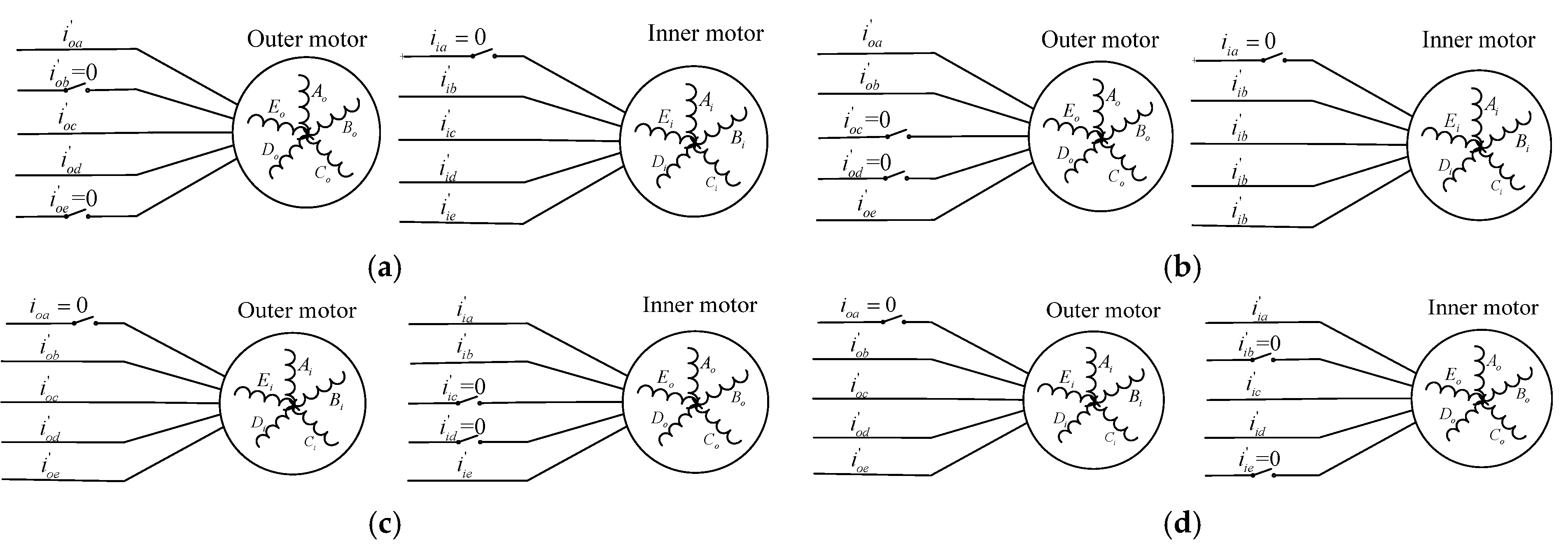
There are also four fault types in this fault situation: (I) Non-adjacent double-phase open-circuit in the outer motor with single-phase open-circuit in the inner motor (
Figure 24a); (II) Adjacent double-phase open-circuit in the outer motor with single-phase open-circuit in the inner motor (
Figure 24b); (III) Adjacent double-phase open-circuit in the inner motor with single-phase open-circuit in the outer motor (
Figure 24c); (IV) Non-adjacent double-phase open-circuit in the inner motor with single-phase open-circuit in the outer motor (
Figure 24d). As in the case of the single-phase open-circuit fault in both the inner motor and outer motors in
Section 3.1.3, there are also two fault cases for each fault type, and only one fault case is shown in
Figure 24 as an example.
Figure 24.
Double-phase open-circuit in one side of the motor with single-phase open-circuit in another side of the motor fault type (four types).
Figure 24.
Double-phase open-circuit in one side of the motor with single-phase open-circuit in another side of the motor fault type (four types).
In fault type (I), phases “b” and “e” in the outer motor and phase “a” in inner motor being open-circuit is a one fault case, while phases “c” and “a” in the outer motor and phase “a” in the inner motor being open-circuit, is another fault case. They are not exactly the same due to differences in the torque ripple details. The other fault types are the same as fault type (I).
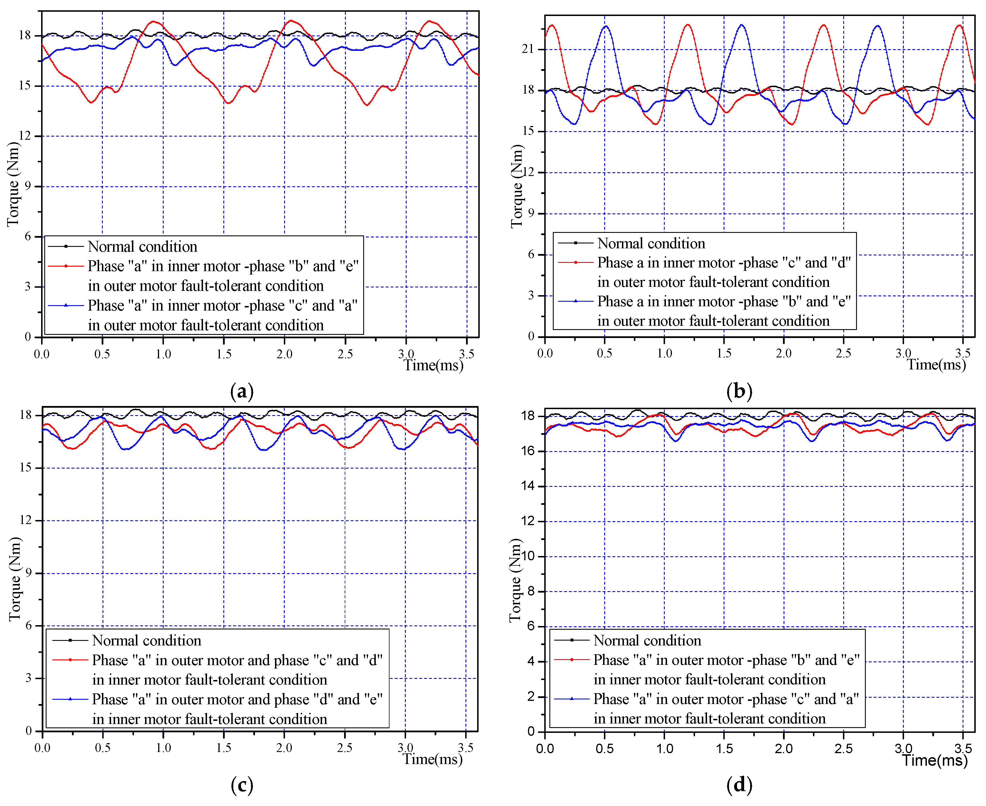
Figure 25 shows the results of two fault cases for each fault type obtained by FEA, from which we can see the average electromagnetic torque is almost the same while there is a larger difference in torque ripple between the different fault cases for each fault type.
Table 12 shows the electromagnetic torque details.
Figure 25.
The electromagnetic torque obtained by FEA under double phase open circuit fault in one motor with single phase open circuit in another motor: (a) fault type I; (b) fault type II; (c) fault type III; (d) fault type IV.
Figure 25.
The electromagnetic torque obtained by FEA under double phase open circuit fault in one motor with single phase open circuit in another motor: (a) fault type I; (b) fault type II; (c) fault type III; (d) fault type IV.
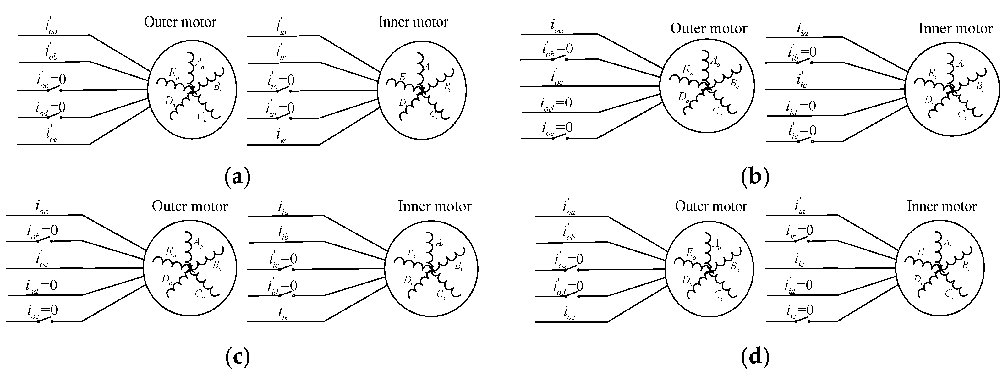
3.4. Double-Phase Open-Circuit in Both Sides of the Motor Fault-Tolerance Technique
There are also four fault types in this fault situation: (I) Adjacent double-phase open-circuit in outer motor and in inner motor (
Figure 26a); (II) Non-adjacent double-phase open-circuit in outer motor and in inner motor (
Figure 26b); (III) Adjacent double-phase open-circuit in inner motor with non-adjacent double-phase open-circuit in outer motor (
Figure 26c); (IV) Non-adjacent double-phase open-circuit in inner motor with adjacent double-phase open-circuit in outer motor (
Figure 26d). As in the case of the single-phase open-circuit fault in both inner motor and outer motor in
Section 3.1.1, there are three fault cases for each fault type, and only one fault case is shown in
Figure 26 as an example.
Table 12.
The details of electromagnetic torque under double phase open circuit fault in one side of motor with single phase open circuit in another side of the motor.
Table 12.
The details of electromagnetic torque under double phase open circuit fault in one side of motor with single phase open circuit in another side of the motor.
| Motor Fault Types * | Examples of Open-Circuit Fault Cases for Each Fault Type | Average Output Torque (Nm) | Torque Ripple (Percent) |
|---|
| Fault type (I) | Phase “a” in inner motor, phases “b” and “e” in outer motor are open circuit | 16.34 | 31.0% |
| Phase “a” in inner motor, phases “a” and “c” in outer motor are open circuit | 17.25 | 9.9% |
| Fault type (II) | Phase “a” in inner motor, phases “c” and “d” in outer motor are open circuit | 17.78 | 35.1% |
| Phase “a” in inner motor, phases “d” and “e” in outer motor are open circuit | 18.00 | 32.1% |
| Fault type (III) | Phase “a” in outer motor, phases “c” and “d” in inner motor are open circuit | 17.10 | 9.8% |
| Phase “a” in outer motor, phases “d” and “e” in inner motor are open circuit | 17.01 | 11.5% |
| Fault type (IV) | Phase “a” in outer motor, phases “b” and “e” in inner motor are open circuit | 17.42 | 7.5% |
| Phase “a” in outer motor, phases “a” and “c” in inner motor are open circuit | 17.44 | 6.9% |
Figure 26.
Double-phase open-circuit in both sides of motor fault types. (a) Adjacent double-phase open-circuit in outer motor and in inner motor; (b) non-adjacent double-phase open-circuit in outer motor and in inner motor; (c) adjacent double-phase open-circuit in inner motor with non-adjacent double-phase open-circuit in outer motor; (d) non-adjacent double-phase open-circuit in inner motor with adjacent double-phase open-circuit in outer motor.
In fault type (I), phases “c” and “d” in inner motor and phase “c” and “d” in outer motor being open-circuit is one fault case, while phase “c” and “d” in inner motor and phase “d” and “e” in outer motor being open-circuit is the other fault case, and phase “c” and “d” in inner motor and phase “e” and “a” in outer motor being open-circuit is another new fault case. They are not exactly the same due to differences in the torque ripple. The different fault cases for each fault type are shown in
Table 12.
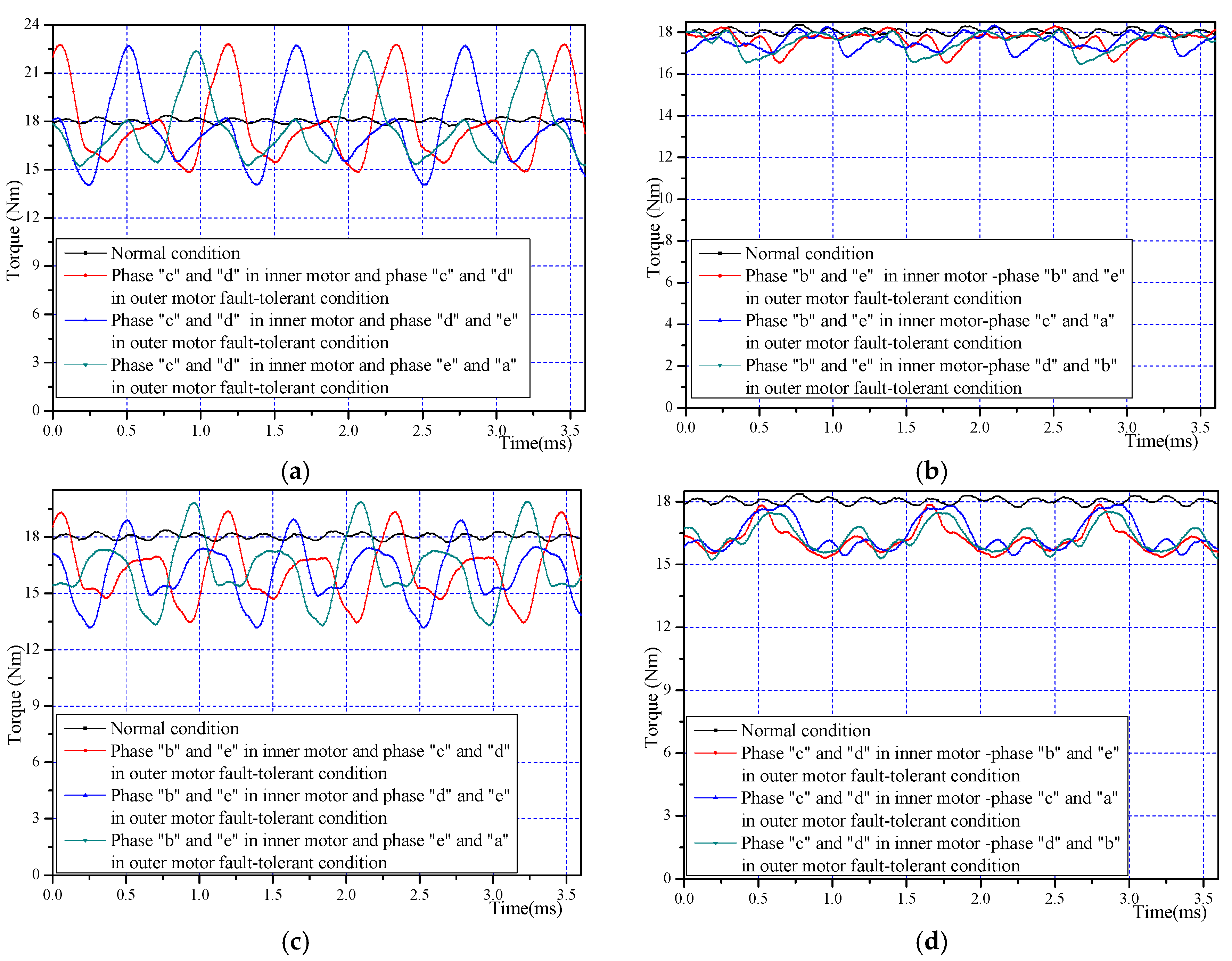
Figure 27 shows the torque results of different fault cases for each fault type obtained by FEA. Through these comparisons, it can be seen that the adjacent double phase fault in the outer motor is the most severe fault type.
Table 13 shows the torque details. The average electromagnetic torque under different fault cases for each fault type is almost the same, but the difference in torque ripple is obvious.
Figure 27.
The electromagnetic torque obtained by FEA under double-phase open-circuit in both sides of motor fault condition (a) fault type I; (b) fault type II; (c) fault type III; (d) fault type IV.
Figure 27.
The electromagnetic torque obtained by FEA under double-phase open-circuit in both sides of motor fault condition (a) fault type I; (b) fault type II; (c) fault type III; (d) fault type IV.
Table 13.
The details of electromagnetic torque under double phase open circuit in both sides of the motor fault condition.
Table 13.
The details of electromagnetic torque under double phase open circuit in both sides of the motor fault condition.
| Double-Phase Open-Circuit in Both Sides of Motor Fault Types | Examples of Open-Circuit Fault Cases of Each Fault Type | Average Output Torque (Nm) | Torque Ripple (Percent) |
|---|
| Fault type (I) | Phases “c” and “d” in inner motor, phases “c” and “d” in outer motor are open circuit | 17.86 | 42.1% |
| Phases “c” and “d” in inner motor, phases “d” and “e” in outer motor are open circuit | 17.55 | 41.3% |
| Phases “c” and “d” in inner motor, phases “e” and “a” in outer motor are open circuit | 17.65 | 40.1% |
| Fault type (II) | Phases “b” and “e” in inner motor, phases “b” and “e” in outer motor are open circuit | 17.66 | 9.9% |
| Phases “b” and “e” in inner motor, phases “c” and “a” in outer motor are open circuit | 17.54 | 8.7% |
| Phases “b” and “e” in inner motor, phases “d” and “b” in outer motor are open circuit | 17.56 | 9.5% |
| Fault type (III) | Phases “b” and “e” in inner motor, phases “c” and “d” in outer motor are open circuit | 16.23 | 36.4% |
| Phases “b” and “e” in inner motor, phases “d” and “e” in outer motor are open circuit | 16.09 | 35.9% |
| Phases “b” and “e” in inner motor, phases “e” and “a” in outer motor are open circuit | 16.35 | 40.2% |
| Fault type (IV) | Phases “c” and “d” in inner motor, phases “b” and “e” in outer motor are open circuit | 16.19 | 15.7% |
| Phases “c” and “d” in inner motor, phases “c” and “a” in outer motor are open circuit | 16.44 | 14.7% |
| Phases “c” and “d” in inner motor, phases “d” and “b” in outer motor are open circuit | 16.31 | 14.0% |
4. Co-Simulation Results
In this section, the co-simulation results based on Simulink-Simplorer-Maxwell are illustrated to verify the effectiveness of the aforementioned techniques. Maxwell is community software for design of electrical motors but it lacks facilities for the design of drivers. On the other hand, the model of power electronic components is more accurate in Simplorer software compared to Simulink, which can provide a suitable environment for designing controllers [
33,
34]. In this paper, the DRPMSM is designed in Maxwell, and the driver circuit is designed in Simplorer in which the details of IGBTS are listed. Meanwhile, the fault tolerant controller is designed in Simulink. By linking these, an appropriate tool is provided for a realistic fault-tolerant driver with a five-phase DRPMSM.
Figure 28 shows the finite element model of the motor designed in Maxwell and
Table 14 shows some of the parameters of the five-phase DRPMSM.
Figure 28.
Finite element model of the five-phase DRPMSM.
Figure 28.
Finite element model of the five-phase DRPMSM.
Table 14.
Some of the design and electrical parameters of the DRPMSM in Maxwell.
Table 14.
Some of the design and electrical parameters of the DRPMSM in Maxwell.
| Parameter | Unit | Five-Phase DRPMSM |
|---|
| Rate power | Kw | 2 |
| Rate speed | rpm | 1200 |
| Outer rotor out diameter | mm | 225 |
| Outer rotor in diameter | mm | 197 |
| Stator outer diameter | mm | 195.5 |
| Stator inner diameter | mm | 153 |
| Inner rotor out diameter | mm | 115.8 |
| Inner rotor inner diameter | mm | 92 |
| Rotor stack length | mm | 38.5 |
| Stator stack length | mm | 38.5 |
| Air gap | mm | 0.75 |
| Number of stator slots | - | 40 |
| Number of rotor poles | - | 44 |
| Stator resistance of each phase of inner motor | mΩ | 320 |
| Stator resistance of each phase of outer motor | mΩ | 310 |
| Stator inductance of each phase of inner motor | μH | 746.3 |
| Stator inductance of each phase of outer motor | μH | 739.3 |
| Current density | A/mm2 | 4.48 |
| Linear current load | KA/m | 10.95 |
The fault tolerant algorithm was accomplished in Simulink on the basis of the fault tolerant techniques investigated above. In order to ensure the injected currents are more flexible, the current hysteresis control technique is adopted. Operated under normal conditions, the control scheme is shown in
Figure 2. When an open circuit fault occurs in the machine or the driver, whereby the fault type should be detected first, the corresponding injected currents are produced by fault-tolerant control algorithms.
Figure 29 shows the fault tolerant control block diagram which adopts hysteresis control in the current loop in serial drive mode. Open circuit fault type can be detected through the current detection followed by the control scheme switch to fault tolerant control algorithm.
Figure 29.
Control block diagram of fault tolerant system.
Figure 29.
Control block diagram of fault tolerant system.
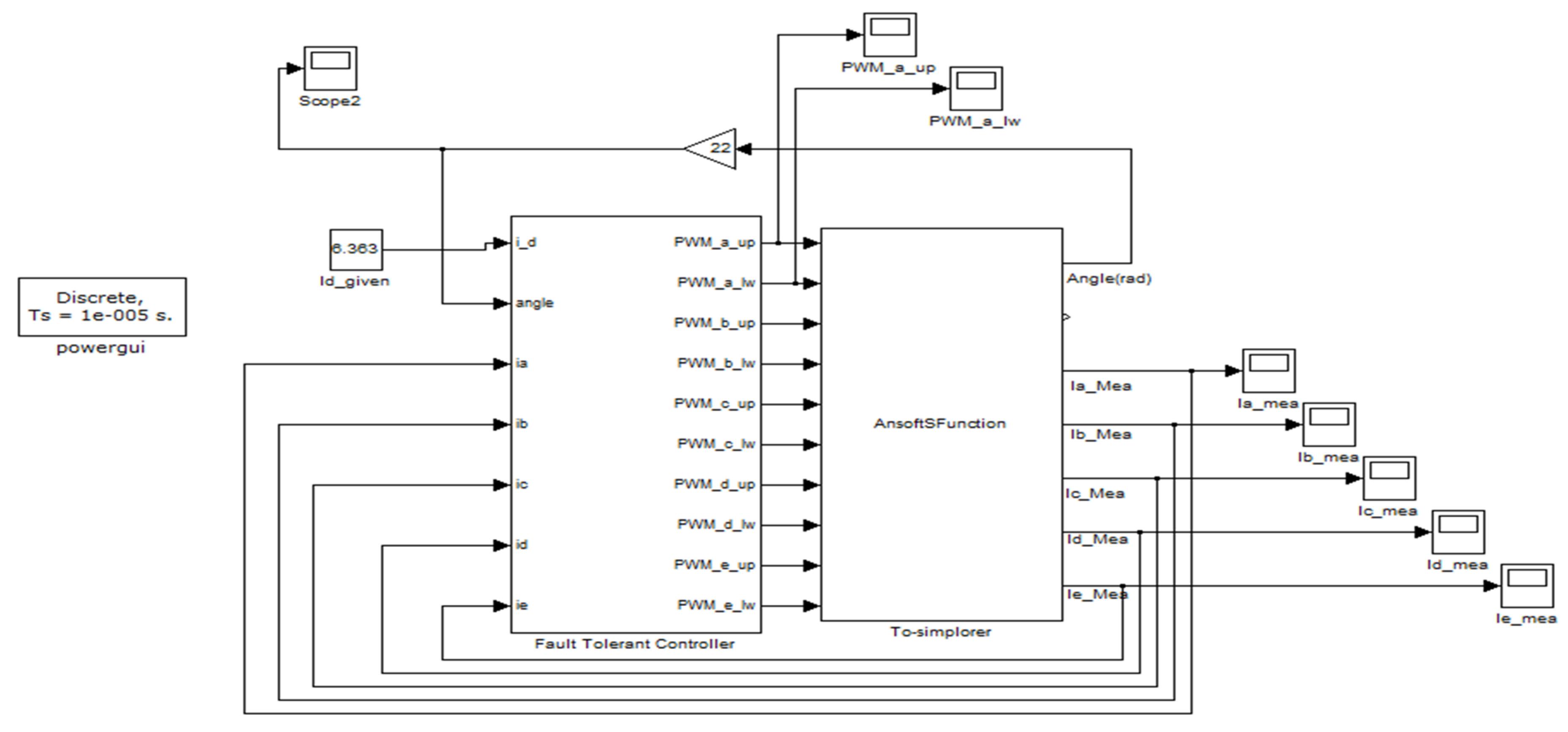
Figure 30 shows the fault tolerant control structure in Simulink.
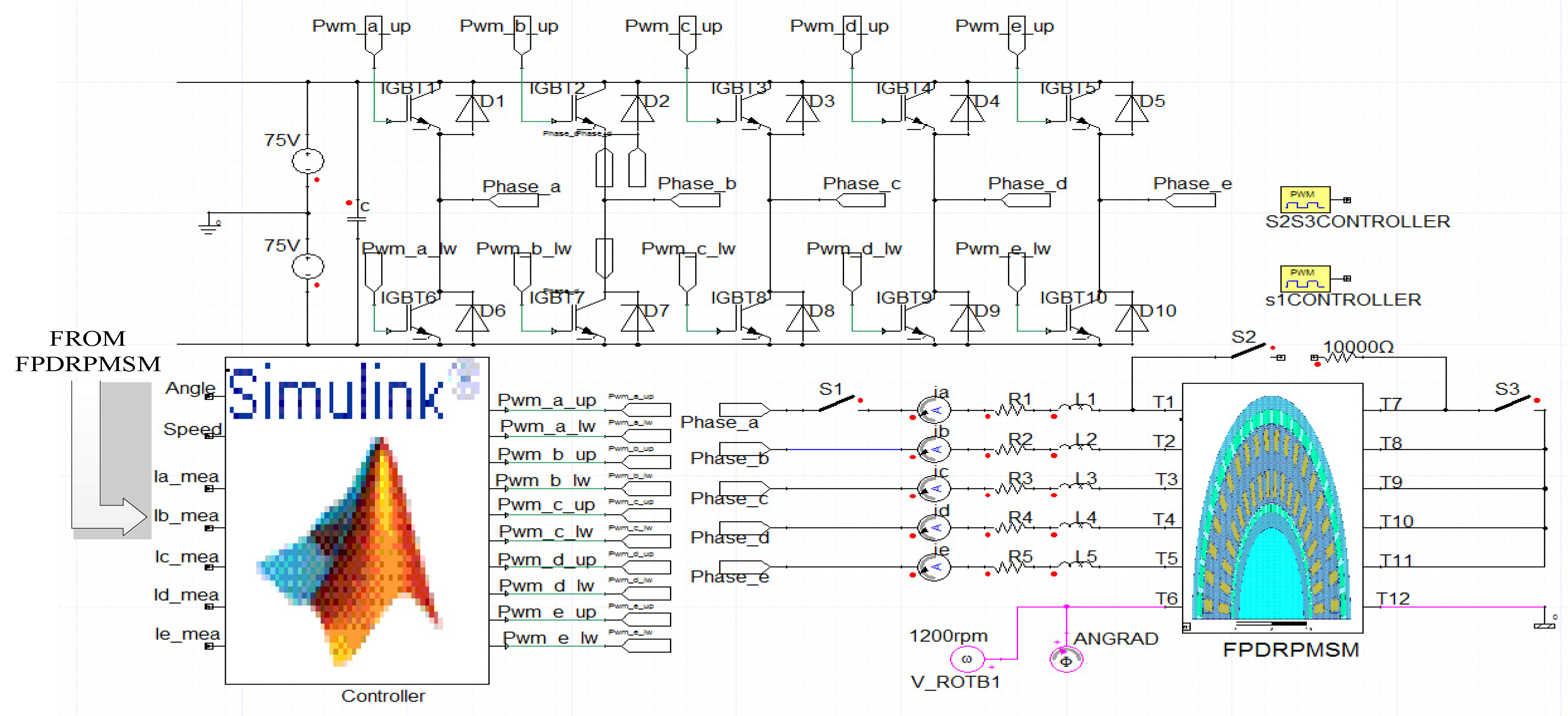
Figure 31 shows the main driver circuits in Simplorer. As we know, the resistance of each stator winding is not considered in the FEA model, and, in order to simulate the real situation better, R
1–R
5 are added in Simplorer. Their values are equal to
Ri +
Ro, in which
Ri = 320 mΩ and
Ro = 310 mΩ are respectively stator resistances of each phase of the inner motor and the outer motor. L
1–L
5 = 0.1 μH are the end-leakage inductance of each phase which is very small, and are simply fictitious and must be added to achieve the simulation. Different work conditions are simulated by controlling the switch S
1–S
3. In this section, co-simulation results of two typical fault types will be displayed. They are the single phase open-circuit fault type in series drive mode and the double-phase open-circuit in one side of the motor with single-phase open-circuit in another side of motor fault type in the parallel drive mode. It should be noted that the DC-bus voltage is 150 V as the machine operates in series drive mode. However, the DC-bus voltage is 95 V for outer motor’s inverter and 55 V for inner motor’s inverter as the machine operates in parallel drive mode. They are representative to verify the effectiveness of the fault techniques, and simulation of other fault types is similar to these two fault types.
Figure 30.
Fault tolerant control structure in Simulink.
Figure 30.
Fault tolerant control structure in Simulink.
Figure 31.
The main driver circuit in Simplorer.
Figure 31.
The main driver circuit in Simplorer.
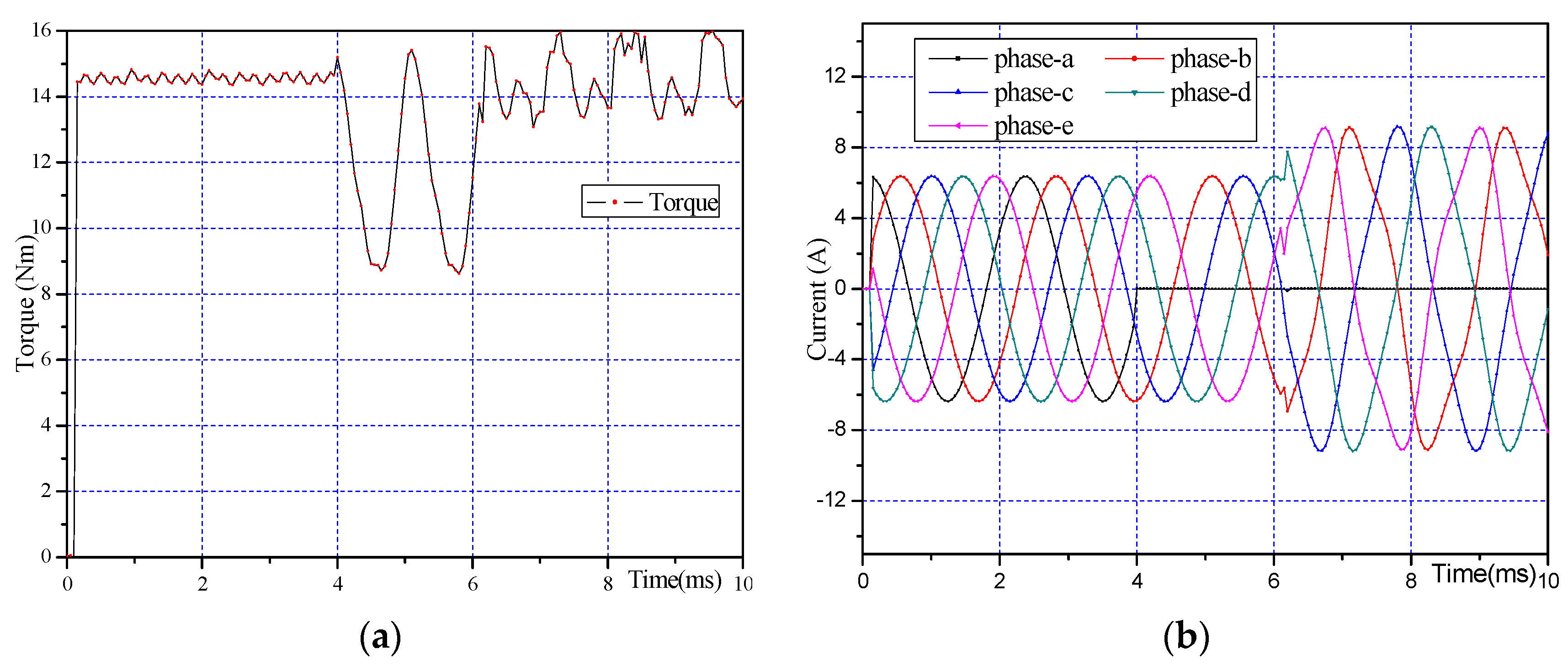
Torque and current waveforms of the motor when phase an open circuit fault occurs in serial drive mode are shown in
Figure 32. As mentioned, the fault occurs at 4 ms, and the fault tolerant technique that injects currents contains third harmonics is adopted at 6 ms. When the motor operates under normal conditions (0–4 ms), the electromagnetic torque is about 14.7 Nm with 3.2% ripple. Compared to the results obtained by FEA, the co-simulation electromagnetic torque is reduced because it considers switching losses and the resistance and leakage inductance of each phase. In this machine, the stator resistances of each phase of the inner motor and the outer motor are
Ri = 320 mΩ and
Ro = 310 mΩ, respectively. Operating in series drive mode, the stator resistance can be seen as a superposition of
Ri and
Ro. Ignoring the losses caused by the third harmonic currents, power loss of each VSI legs can be expressed as:
in which,
Ps-l is Power loss of each VSI leg in serial drive mode,
Ts-f = 18.08 Nm is torque obtained by FEA in serial drive mode,
Ts-c = 14.7 Nm is torque obtained by co-simulation results,
Is-rms = 6.36/
A is RMS values that pass each phase. We can calculate that
Ps-l is equal to 76 W. As fault occurs at 4 ms, the electromagnetic torque reduced to 11.66 Nm with torque ripple of 58.3%. However, when the fault technique is adopted at 6 ms, the electromagnetic torque is 14.50 Nm with torque ripple of 20.0%. The torque ripple is larger than FEA results because of the instability of switching frequency produced by current hysteresis control.
Figure 32.
The co-simulation results (a) electromagnetic torque and (b) current changes when open-circuit fault occurs in phase “a” in serial drive mode (Phase “a” open circuit fault point: 4 ms; injecting the fault-tolerant current point: 6 ms).
Figure 32.
The co-simulation results (a) electromagnetic torque and (b) current changes when open-circuit fault occurs in phase “a” in serial drive mode (Phase “a” open circuit fault point: 4 ms; injecting the fault-tolerant current point: 6 ms).
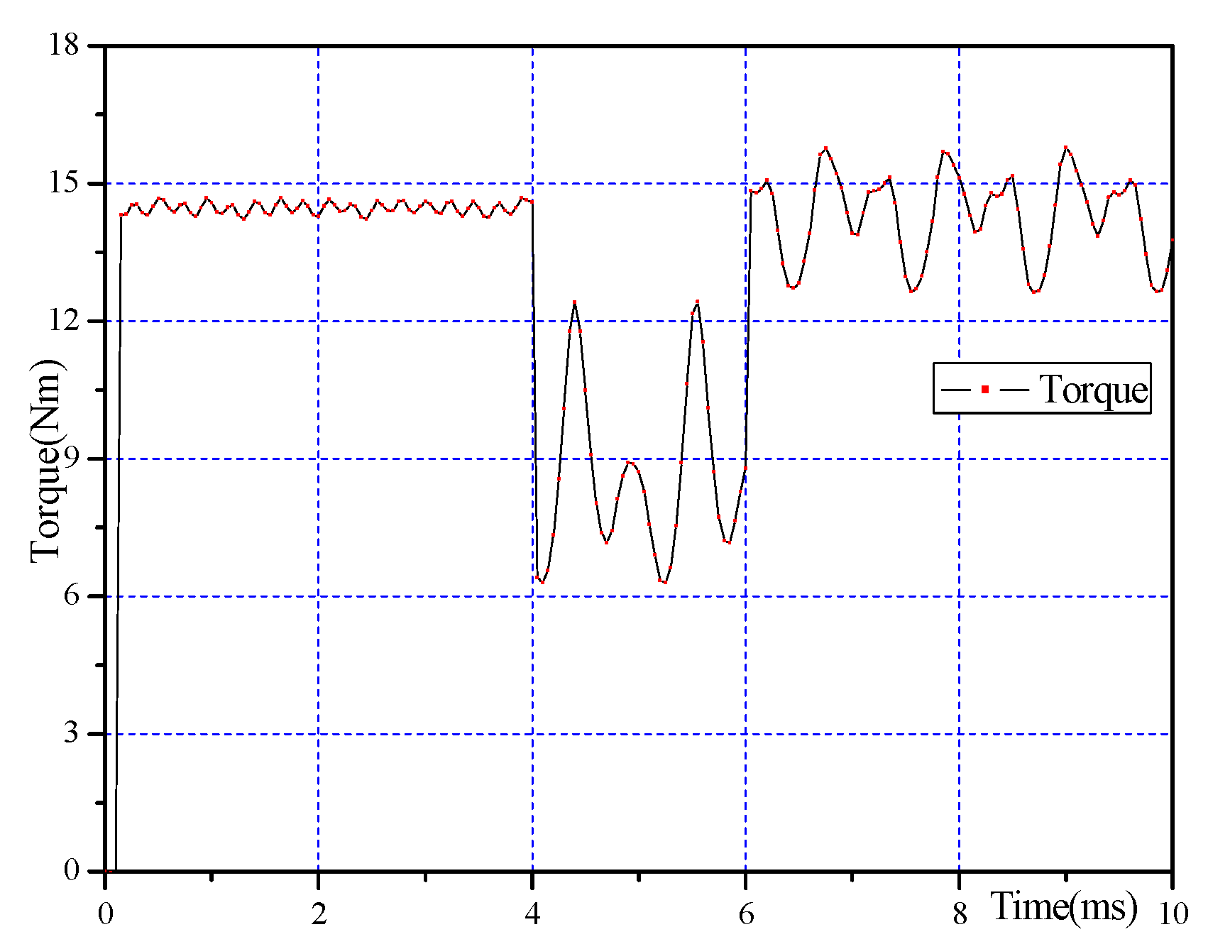
Figure 33 shows the torque changes when phase “a” in the outer motor and phases “b” and “e” in the inner motor open-circuit fault occurs in parallel drive mode. Under normal conditions (0~4 ms), the electromagnetic torque is 14.41 Nm with 3.8% ripple. The same as in the serial drive mode, power loss of each VSI leg can be expressed as:
in which,
Pp−l is power loss of each VSI leg in parallel drive mode,
Tp−f = 18.08 Nm is torque obtained by FEA in parallel drive mode,
Ts−c =14.41 Nm is torque obtained by co-simulation results,
Ii−rms = 6.36/
A is RMS values that pass inner motor,
Io−rms = 6.36/
A is RMS values that pass outer motor. We can calculate that
Pp−l is equal to 36 W, which is much smaller than
Ps−l. As a fault occurs at 4 ms, the electromagnetic torque is reduced to 8.56 Nm with 49.3% ripple, whereas 14.31 Nm of torque with 16.2% ripple is produced under fault-tolerant conditions (6–10 ms).
Figure 33.
The co-simulation electromagnetic torque when the open-circuit fault occurs in phase “a” of outer motor and phases “b” and “e” of inner motor in parallel drive mode (open circuit fault point: 4 ms; injecting the fault current point: 6 ms).
Figure 33.
The co-simulation electromagnetic torque when the open-circuit fault occurs in phase “a” of outer motor and phases “b” and “e” of inner motor in parallel drive mode (open circuit fault point: 4 ms; injecting the fault current point: 6 ms).
5. Analysis and Discussion of Results
From the above results, it can be found that the average torque can be maintained at 93.8%–99.8% of the normal torque after the open-circuit fault-tolerant techniques are adopted in either serial drive mode or parallel drive mode. However, the torque ripple is still larger than under normal conditions. When the motor operates in serial drive mode, under single-phase open-circuit fault conditions, the fault-tolerant technique only needs smaller excitation current. However, fault tolerant currents are larger for double-phase fault types, especially for adjacent double phase faults. For adjacent double-phase faults, the additional degree of freedom can be used to constrain the fundamental components to be equal or to satisfy zero sixth-order torque pulsation. Both these two solutions are solved and the torques produced respectively by the two solutions are compared. The solution for which the additional degrees of freedom are used to eliminate sixth-order torque pulsating is adopted for smaller torque ripple. However, the additional degrees of freedom are used to reduce the fundamental amplitude value of fault-tolerant currents under non-adjacent double phase fault conditions. It is worth noting that the adjacent double phase fault is the most severe of all the fault types.
When the motor operates in parallel drive mode, due to the big difference of back EMF between the inner motor and outer motor, the third harmonic component in injected excitation currents can be determined separately whether under normal conditions or fault tolerant conditions. The inner motor and outer motor are decoupled. A fault that occurs in one side of the motor almost does not affect the torque characteristics of the other side of the motor. When the fault occurs in one side of the motor, although the current in this faulty side increases in order to maintain constant torque, the current in the other side of the motor remains normal, thus the thermal of the stator is smaller compared with the condition where faults occurred on both sides. Compared to when the open circuit fault occurs in the outer motor, the average output torque is larger and the torque ripple is smaller when the same fault type occurs in the inner motor. This is because the output torque of the outer motor contributes more than the inner motor. When faults occur in both sides of the motor, different fault cases need to be investigated because they have different torque ripple details. When only one or two circuits are opened, the average torque in parallel drive mode is higher and the thermal of the motor is lower compared to when the motor operates in serial drive mode, which shows the good fault-tolerance capability of the parallel drive mode. Therefore, the motor possesses better fault tolerance performance when operating in parallel drive mode.
6. Conclusions
In this paper, a five-phase DRPMSM in different drive modes and the corresponding fault tolerance techniques are investigated. The FEA results and co-simulation results verify the performances of the fault-tolerance techniques under different fault conditions. The main conclusions are as follows:
(1) When the five-phase DRPMSM operates in serial drive mode, three different fault types and corresponding fault tolerant techniques are investigated. When the three types of faults occur, by adopting the fault tolerance techniques, the average torque can maintained at 93.8%–98% of the normal torque and the torque-ripple can be reduced significantly compared to that without fault tolerance control.
(2) When the five-phase DRPMSM operates in parallel drive mode, the third harmonic content of injected currents can be controlled respectively according to the third harmonic contents of the inner and outer back EMFs. Under fault-tolerant conditions, by analyzing the torque produced by the inner motor, outer motor and their linear addition, the inner motor and outer motor are decoupled, and an open-circuit fault in one side of the motor has little impact on the torque characteristics of the other side of the motor.
(3) The fault-tolerance performances of the five-phase DRPMSM in serial drive mode and parallel drive mode are compared. Compared to the motor operating in serial drive mode, the average torque is higher, the torque ripple is lower and the thermal of the motor is lower than when same type of fault occurs when the motor operates in parallel drive mode.
(4) For adjacent double-phase fault types, the additional degrees of freedom can be used to constrain the fundamental components as equal or to eliminate the sixth-order torque ripple. These two different control schemes are compared. The results show that when the additional degrees of freedom are used to eliminate sixth-order torque pulsating, the fault-tolerant torque ripple is smaller.
(5) The performances of the motor under different fault conditions are compared. It is found that the adjacent double phase fault is the most severe fault type among all fault types no matter which drive mode the motor operate in.
(6) The co-simulations based on Simulink-Simplorer-Maxwell illustrate the effectiveness of the fault-tolerance techniques.


