Article

Steady-State Characteristics Analysis of Hybrid-Excited Flux-Switching Machines with Identical Iron Laminations

School of Electrical Engineering, Southeast University, Nanjing 210096, China
*
Author to whom correspondence should be addressed.
Energies 2015, 8(11), 12898-12916; https://doi.org/10.3390/en81112351
Submission received: 30 July 2015 / Accepted: 1 November 2015 / Published: 16 November 2015
(This article belongs to the Special Issue Advances in Plug-in Hybrid Vehicles and Hybrid Vehicles)

Abstract

:
Since the air-gap field of flux-switching permanent magnet (FSPM) machines is difficult to regulate as it is produced by the stator-magnets alone, a type of hybrid-excited flux-switching (HEFS) machine is obtained by reducing the magnet length of an original FSPM machine and introducing a set of field windings into the saved space. In this paper, the steady-state characteristics, especially for the loaded performances of four prototyped HEFS machines, namely, PM-top, PM-middle-1, PM-middle-2, and PM-bottom, are comprehensively compared and evaluated based on both 2D and 3D finite element analysis. Also, the influences of PM materials including ferrite and NdFeB, respectively, on the characteristics of HEFS machines are covered. Particularly, the impacts of magnet movement in the corresponding slot on flux-regulating performances are studied in depth. The best overall performances employing NdFeB can be obtained when magnets are located near the air-gap. The FEA predictions are validated by experimental measurements on corresponding machine prototypes.

Graphical Abstract

1. Introduction

Stator permanent magnet (PM) machines have attracted considerable attention due to their compact and robust rotor structure, concentrated armature windings, and favorable thermal dissipation conditions by locating both magnets and armature windings on stator [1,2,3,4]. Among stator-PM brushless machines, the flux-switching permanent magnet (FSPM) machines exhibit the specific merits of large torque capability, essentially sinusoidal phase PM flux-linkage [5], and consequently phase back electro-motive-force (back-EMF) waveforms with straight rotor and concentrated windings, as well as high power density and high efficiency [6,7,8]. These advantages, along with advanced control strategies [9,10], furnish FSPM machines great potential in modern electrical vehicle (EVs) and hybrid electric vehicle (HEV) applications [11]. However, for solely magnet-excited brushless machines, there a traditional contradiction between the requests of high torque capability and wide speed operation above base speed [12,13,14,15]. Although flux-weakening can be realized by shifting the phase angle of armature current regarding the EMF, i.e., the vector control or the field-orientation control, is more difficult to realize and less effective compared to wound-field machines. Therefore, hybrid-excited flux-switching (HEFS) machines are proposed and considerably attractive [16,17]. Based on the HEFS machines proposed in [17] and shown in Figure 1a, it is easy to deduce two other topologies as shown in Figure 1b,c, respectively, in which the middle and bottom of magnets are kept, and the saved room is left for the field windings. According to PM locations, the HEFS machines are named PM-top, PM-bottom, PM-middle-1 HEFS machines, respectively [18,19]. Then, an improved topology of the PM-middle-1 machine is proposed in [20] to enhance the flux-regulation capability, which is named as PM-middle-2 HEFS machine, as shown in Figure 1d. The 3D configurations of each HEFS machine are given in Figure 2.
Figure 1. Cross sections of the 12-stator-slots/10-rotor-poles HEFS machines. (a) PM-top; (b) PM-bottom; (c) PM-middle-1; (d) PM-middle-2.
Energies 08 12351 g001
Figure 2. 3D configurations of the 12-stator-slots/10-rotor-poles HEFS machines. (a) PM-top; (b) PM-bottom; (c) PM-middle-1; (d) PM-middle-2.
Energies 08 12351 g002
Although the no-load flux-regulation theories and principles of these four HEFS machines were investigated in [19,20], comprehensive comparisons of these machines have not been described, especially for their loaded performances, which are more important for practical applications. Hence, in this paper, first of all, the hybrid-excitation function of each machine is reviewed briefly in Section 2. Then, the no-load end-effect is investigated by 3D finite element analysis (FEA). Thereafter, the electromagnetic performances under loaded conditions are studied in Section 3, with particular attention paid to the PM-middle-2 machine in Section 4. Moreover, the thermal distributions of each HEFS machine are studied in Section 5. In Section 6, the FEA predictions are validated by experimental measurements on the corresponding prototypes. Finally, a comprehensive and quantitative comparison of these HEFS machines is given in Section 7.

2. Design Considerations, Hybrid-Excitation Principles, and 3D End-Effect

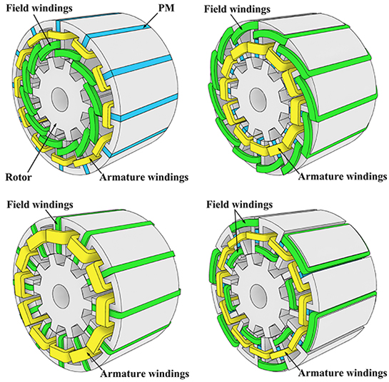
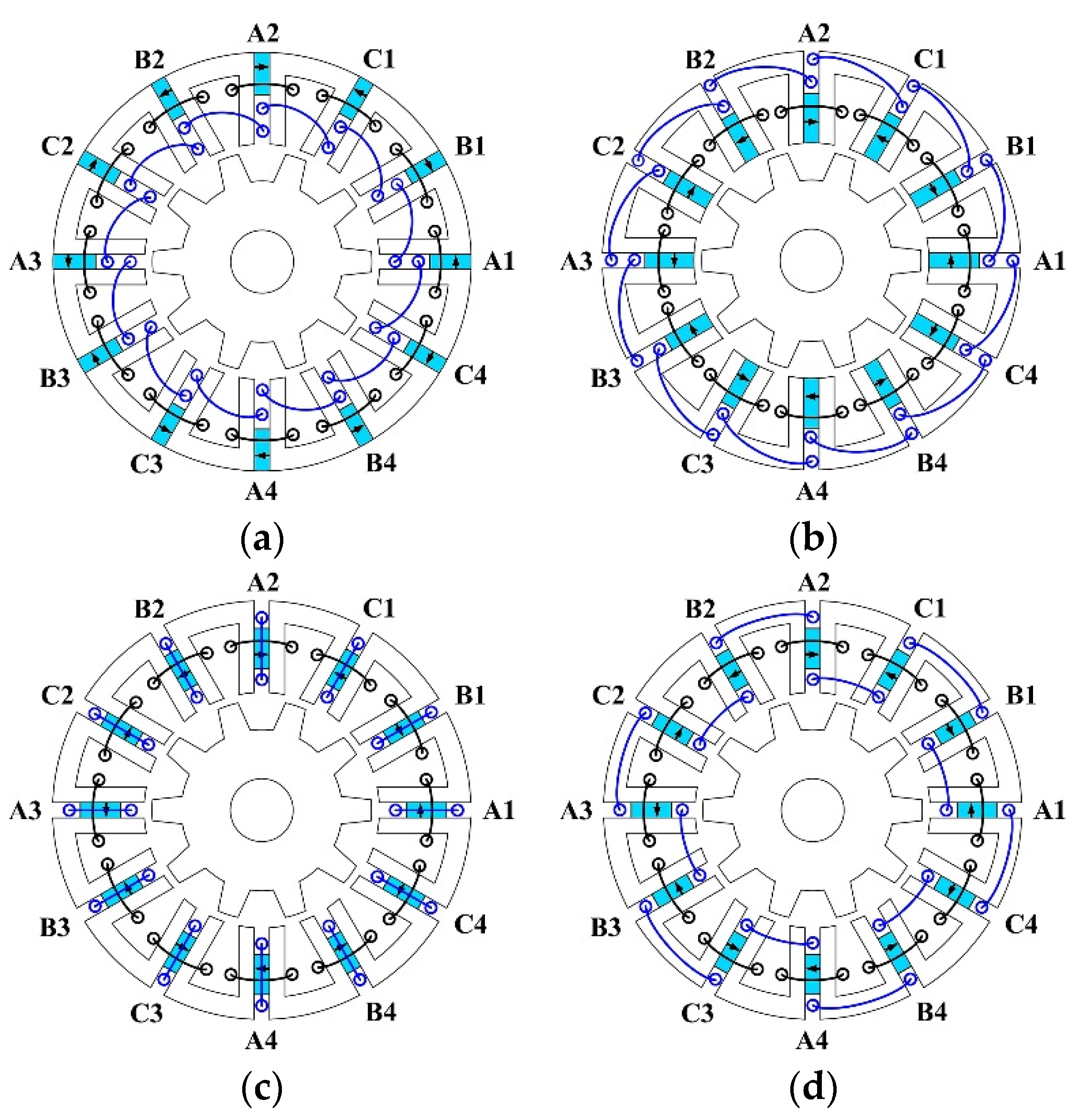
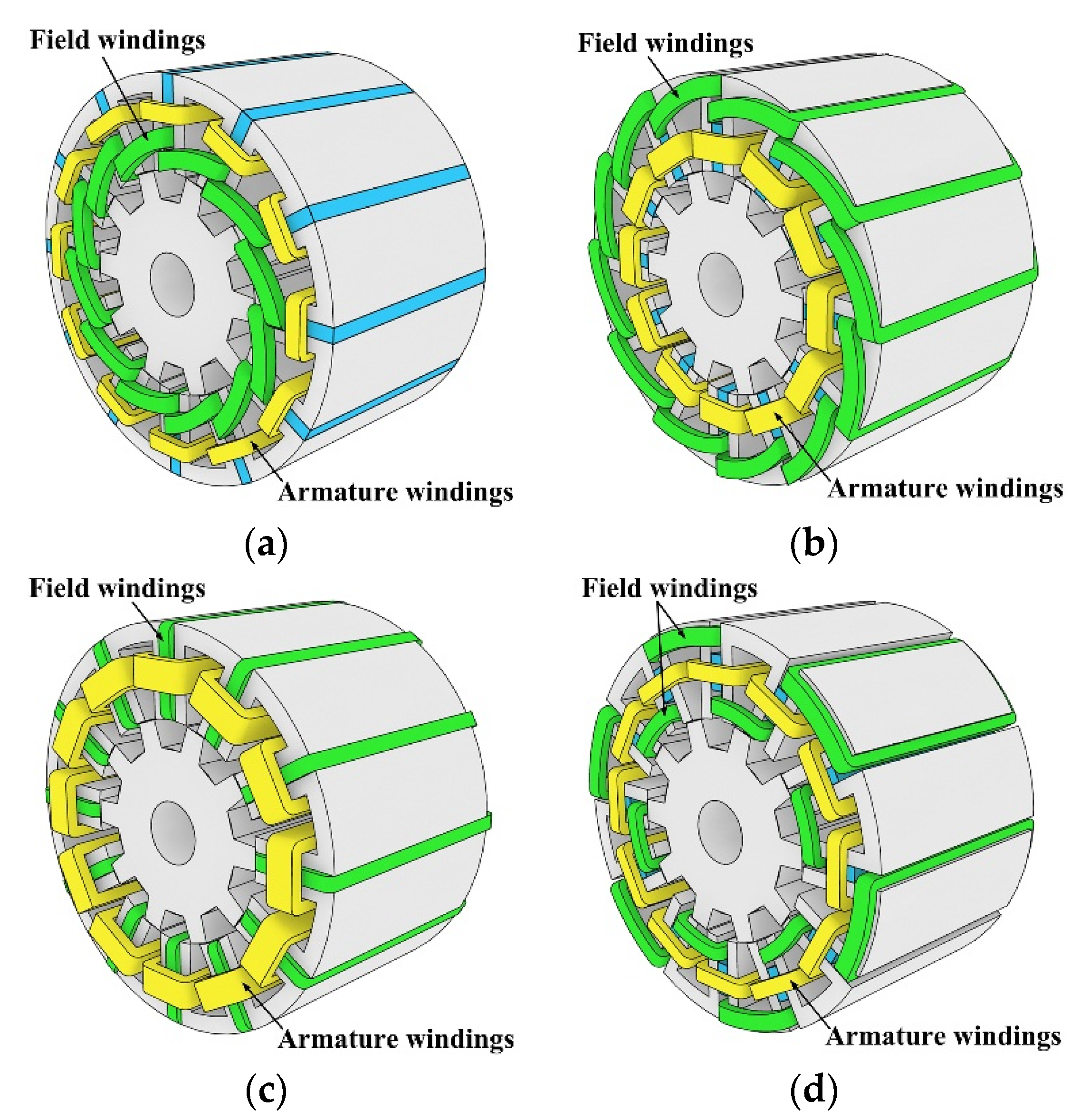
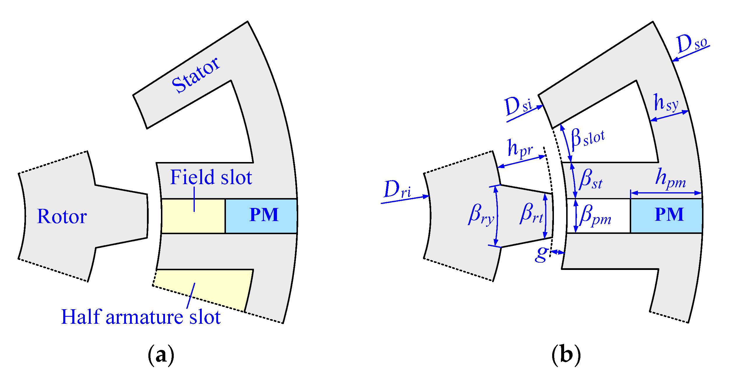
2.1. Design Considerations

For each HEFS machine topology, 12 concentrated field-winding coils, 12 concentrated armature-winding coils, and 12 pieces of magnets are all accommodated in the stator, and a simple and robust rotor is employed as well. The stator lamination, which is constituted by 12 U-shaped core cells, and the rotor lamination, which is similar to that of a switched reluctance machine, is the same for the four HEFS machines under discussion, and the employed lamination material is 35WW470. Both the working frequency and lamination material will show influences on the B-H curve of motor iron, which may lead to slightly different flux density distributions and iron losses. The unique difference among the four topologies is the accommodations of magnets and field windings, so only the main dimensions of the PM-top HEFS machine are illustrated in Figure 3 and listed in Table 1, and the dimensions of the other HEFS machines are identical, except for the magnets. Compared to the original FSPM machines, only 1/3 of the magnet length is adopted in the corresponding HEFS machines to evaluate the influence of different configurations on performance. The magnet width coefficient kpmw in magnetized direction is defined by Equation (1). Also, the geometrical constraint between the magnet width, stator tooth width, and stator slot width is expressed in Equation (2), where the corresponding symbols are listed in Table 1. Moreover, to investigate the saturation effect on HEFS machines, two conditions of employing different magnet materials, namely, the normal NdFeB with high coercive force and the normal Ferrite with low coercive force, respectively, will be discussed in the following sections:
k p m w = β p m 360 ° / P s / 4
β p m + 2 β s t + β s l o t = 360 ° P s
Figure 3. Configuration and design dimensions of PM-top HEFS machine. (a) Configuration; (b) Design dimensions.
Energies 08 12351 g003
Table 1. Design specifications of the 12-stator-slots/10-rotor-poles HEFS machines.
SymbolQuantityParameters
BrMagnet remanence0.4 T (Ferrite); 1.2 T (NdFeB)
SodStator outer diameter128 mm
SidStator inner diameter70.4 mm
laActive stack length75.0 mm
gAir-gap length0.35 mm
DriRotor inner diameter22.0 mm
PsStator slots number12
PrRotor poles number10
hpmMagnet length9.6 mm
βstStator tooth width7.5°
βpmMagnet width6.75°
βslotArmature slot width8.25°
βrtRotor pole arc10.5°
βryRotor yoke width21°
nTurns per armature coil75

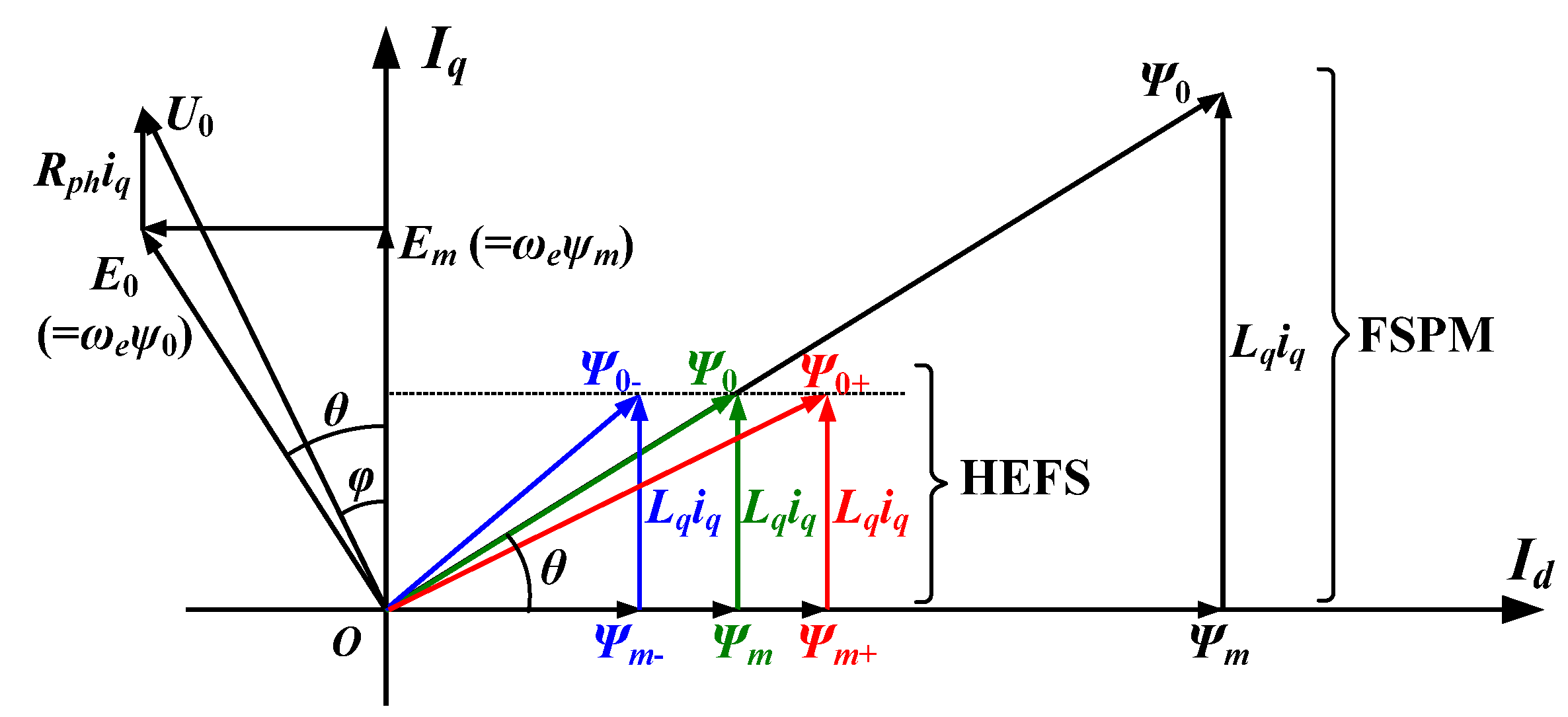
2.2. Hybrid-Excitation Principles

It has been revealed in [19,20] that the magnet location plays an important role in HEFS machines. To clearly demonstrate the flux-regulation principles of these four HEFS machines, the corresponding hybrid-excitation functions are briefly reviewed in this part. Summarily, reversal flux-regulation functions can be realized in the PM-top and PM-bottom topologies by the same field currents. Hence, in the PM-middle-1 machine, the currents in the two field slots adjoining each PM exhibit reversal excitation/flux-regulation functions, since it can be considered as the combination of the PM-top and -bottom ones. Therefore, to improve the flux-regulation capabilities of the PM-middle-1 machine, the PM-middle-2 topology was proposed by reversing the direction of field current in one of the field slots. So, the PM-middle-2 machine shares identical machine structure, i.e., the same iron laminations and PM locations with PM-middle-1 machine, but has different field current directions in some field slots and thus different field winding accommodations. Zhang et al. also proved that the PM-middle-2 machine has much better flux-regulation capability than the PM-middle-1 topology [20].

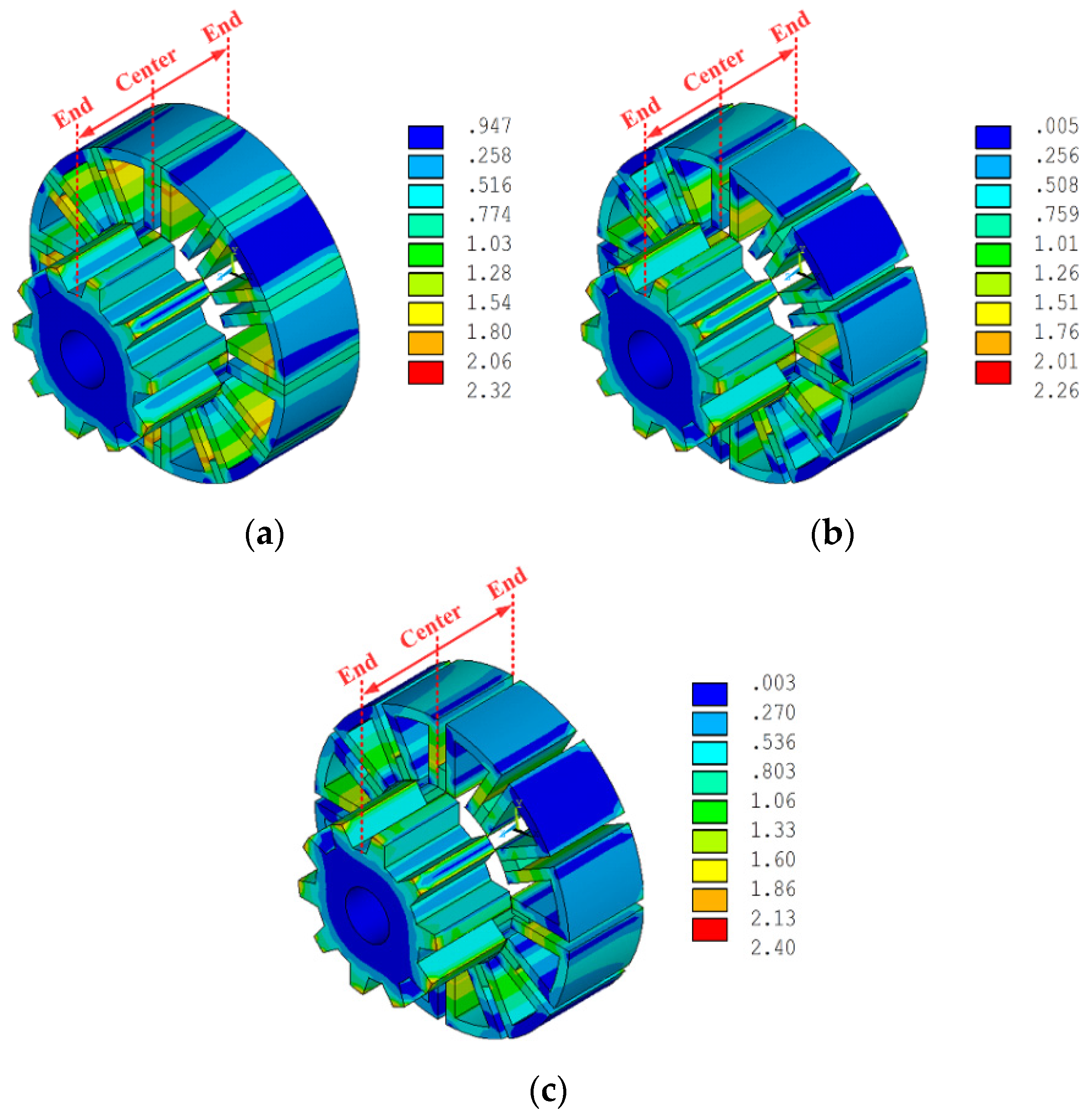
2.3. The 3D End-Effect under No-Load Condition

The distinct magnets and field winding accommodations in these four HEFS machines may cause different axial flux-leakages, so particular attention is paid to the 3D end-effect in this part, which has not been covered in previous work. Figure 4 shows the 3D FEA predicted (by ANSYS) flux-density distributions due to NdFeB when the rotor position is at the d-axis. For a clear observation, half of the stator and rotor are hidden from center to different ends, respectively. Generally, the flux density decreases from the center to the end, and significant saturations can be found at stator and rotor teeth tips. To quantitatively evaluate the influence of 3D end-effect, a coefficient kend is defined by:
k e n d = ψ p m 3 D ψ p m 2 D
where, ψpm−3D and ψpm−2D is 3D- and 2D-predicted phase PM flux linkages, respectively. The no-load kend values due to PM excitation in each HEFS machine are listed in Table 2. As can be seen, kend is slightly greater in the PM-bottom machine. Additionally, ref [20] pointed out that the end-effects also vary with different field currents.
Figure 4. 3D FEA obtained flux density distributions due to NdFeB PMs only. (a) PM-top; (b) PM-bottom; (c) PM-middle-1 & -2.
Energies 08 12351 g004
Table 2. No-load 3D end-effect coefficients kend.
ConditionPM-TopPM-BottomPM-Middle-1 & -2
Adopting Ferrite0.910.920.91
Adopting NdFeB0.920.920.91

3. Loaded Performances
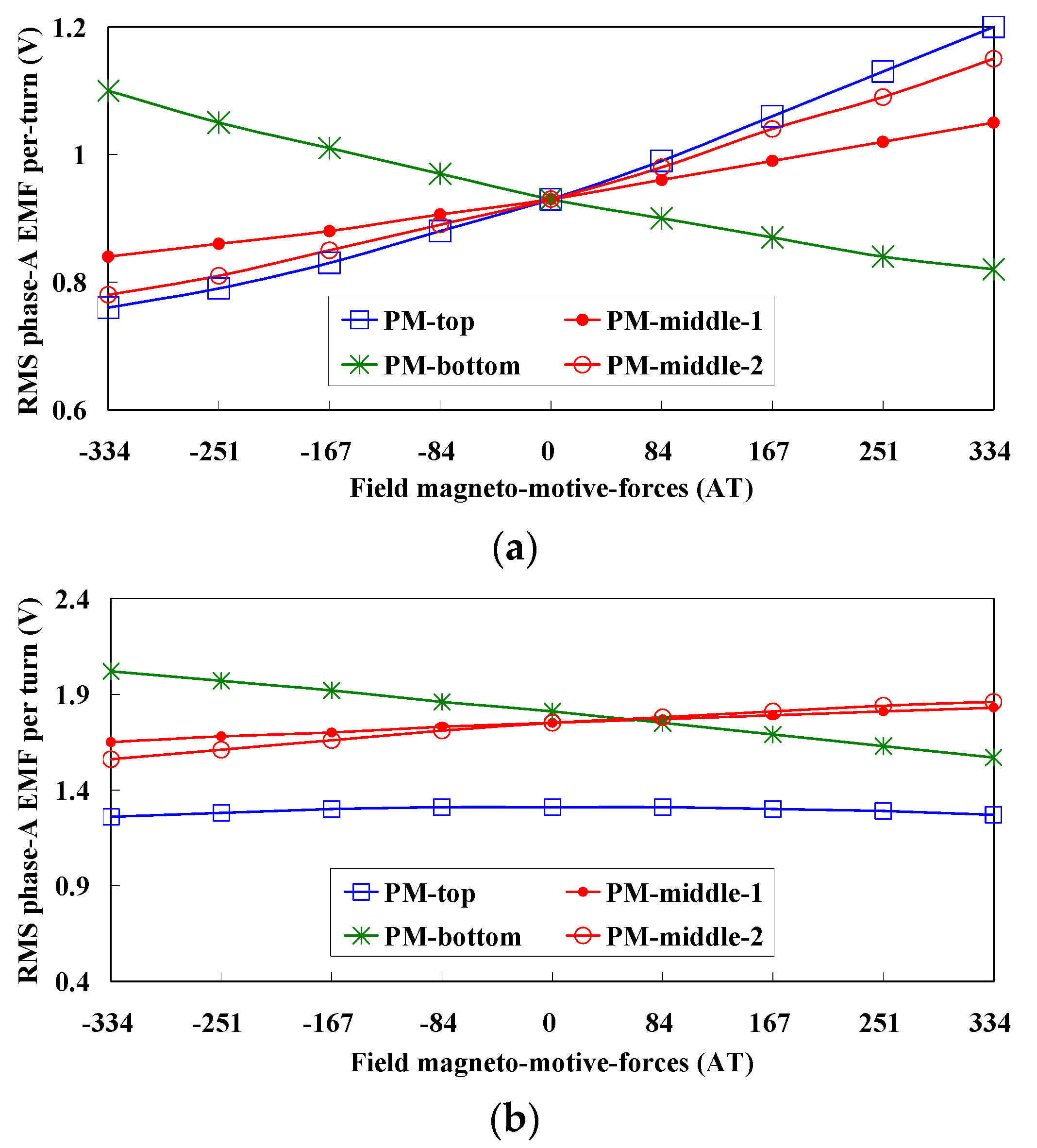
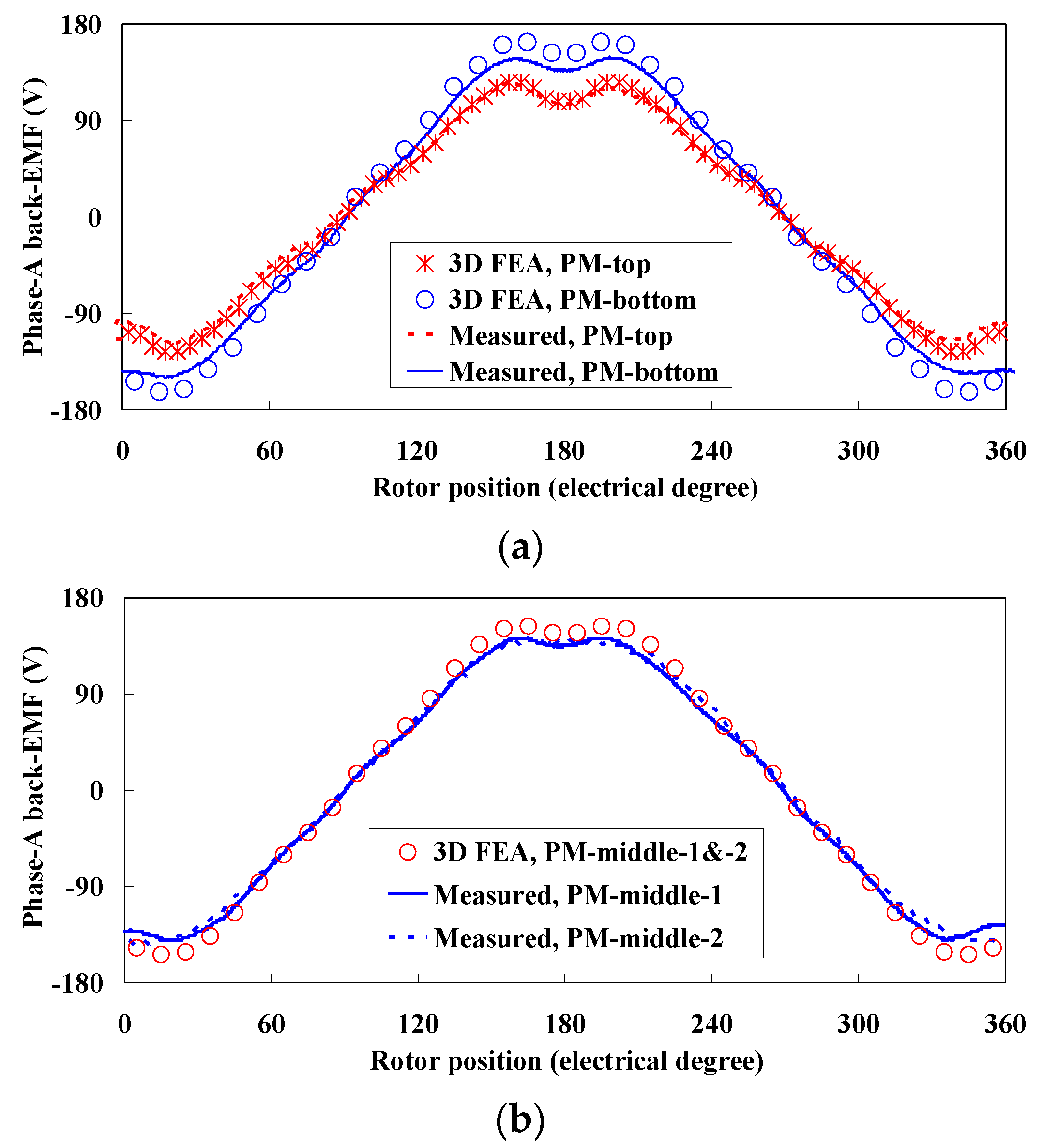
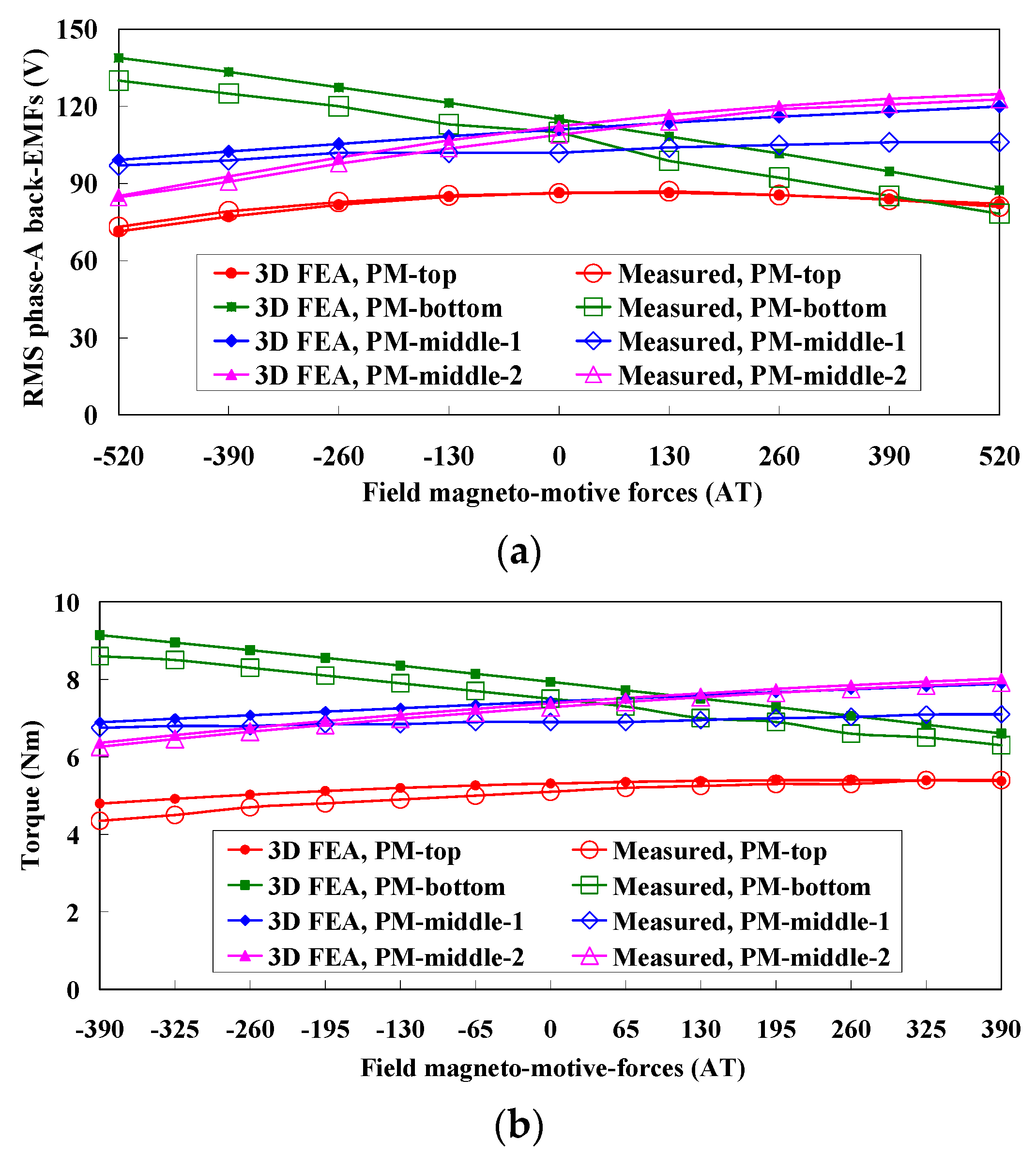
In this section, based 2D FEA (by ANSYS), the loaded performances of these HEFS machines are investigated. When armature currents are applied, Figure 5 illustrates the flux vectors of the FSPM and HEFS machines in the rotor reference frame employing id = 0 control strategy [21], where Ψm is the permanent magnet flux vector, Lq and iq are q-axis inductance and current, respectively. Consequently, the power factor can be obtained by cosθ by neglecting Rphiq. Compared to the FSPM machines, the magnitude of Ψm in the HEFS machines decreases obviously due to the reduction of magnet volume, which consequently requires a much lower Lqiq to maintain the power factor (cosθ) and results in the drawback of a degraded torque density. The FEA predicted steady-state armature load performances, including the phase-A EMFs, averaged electromagnetic torques, torque ripples, and power factors are given in Figure 6, Figure 7, Figure 8 and Figure 9, when an armature current density of RMS 1.4A/mm2 (with a slot fill factor of 0.5, corresponding to RMS 98AT per half armature slot) is applied. For the convenience of analysis, Rphiq is neglected and assuming E0 = U0. The ferrite-related performances are given in this paper to show how these HEFS machines work under a low saturation condition, thus obtain a better understanding of the electromagnetic behaviors when NdFeB is used.
Figure 5. Flux vectors under id = 0 control strategy in the FSPM and HEFS machines.
Energies 08 12351 g005
Figure 6. Variation of phase-A EMF per-turn by different field currents at 1500 r/min. (a) Employing ferrite; (b) Employing NdFeB.
Energies 08 12351 g006
Figure 7. Variation of average torque values by different field currents. (a) Employing ferrite; (b) Employing NdFeB.
Energies 08 12351 g007aEnergies 08 12351 g007b
Figure 8. Variation of torque ripple values by different field currents. (a) Employing ferrite; (b) Employing NdFeB.
Energies 08 12351 g008
Figure 9. Variation of torque ripple values by different field currents. (a) Employing ferrite; (b) Employing NdFeB.
Energies 08 12351 g009aEnergies 08 12351 g009b

3.1. Phase-A EMF

When armature current is applied, the regulations of phase-A EMF (RMS values in one electrical period) by field currents are given in Figure 6, which consists with the armature no-load flux-regulations results. Overall, best flux-regulation ability can be found in the PM-top HEFS machine when adopting Ferrite, and in the PM-bottom machine when adopting NdFeB. Particularly, the variation of phase-A EMF values in PM-top machine can be neglected when NdFeB is employed. Overall, the regulations of the PM-middle-2 machine are slightly better than that of the PM-middle-1 machine.

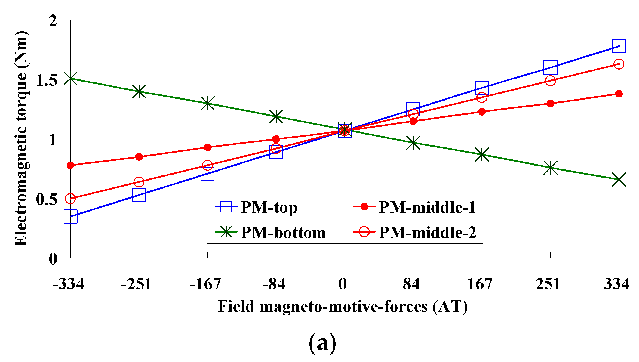
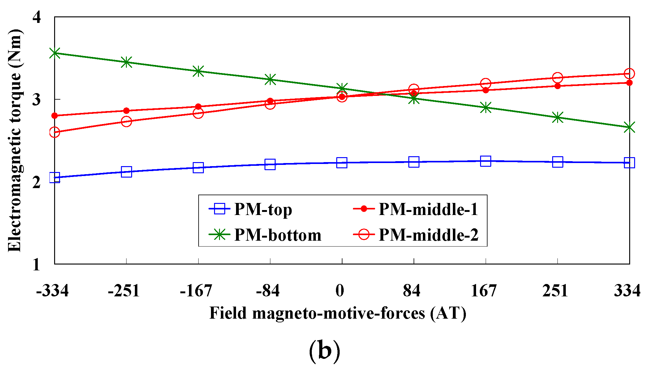
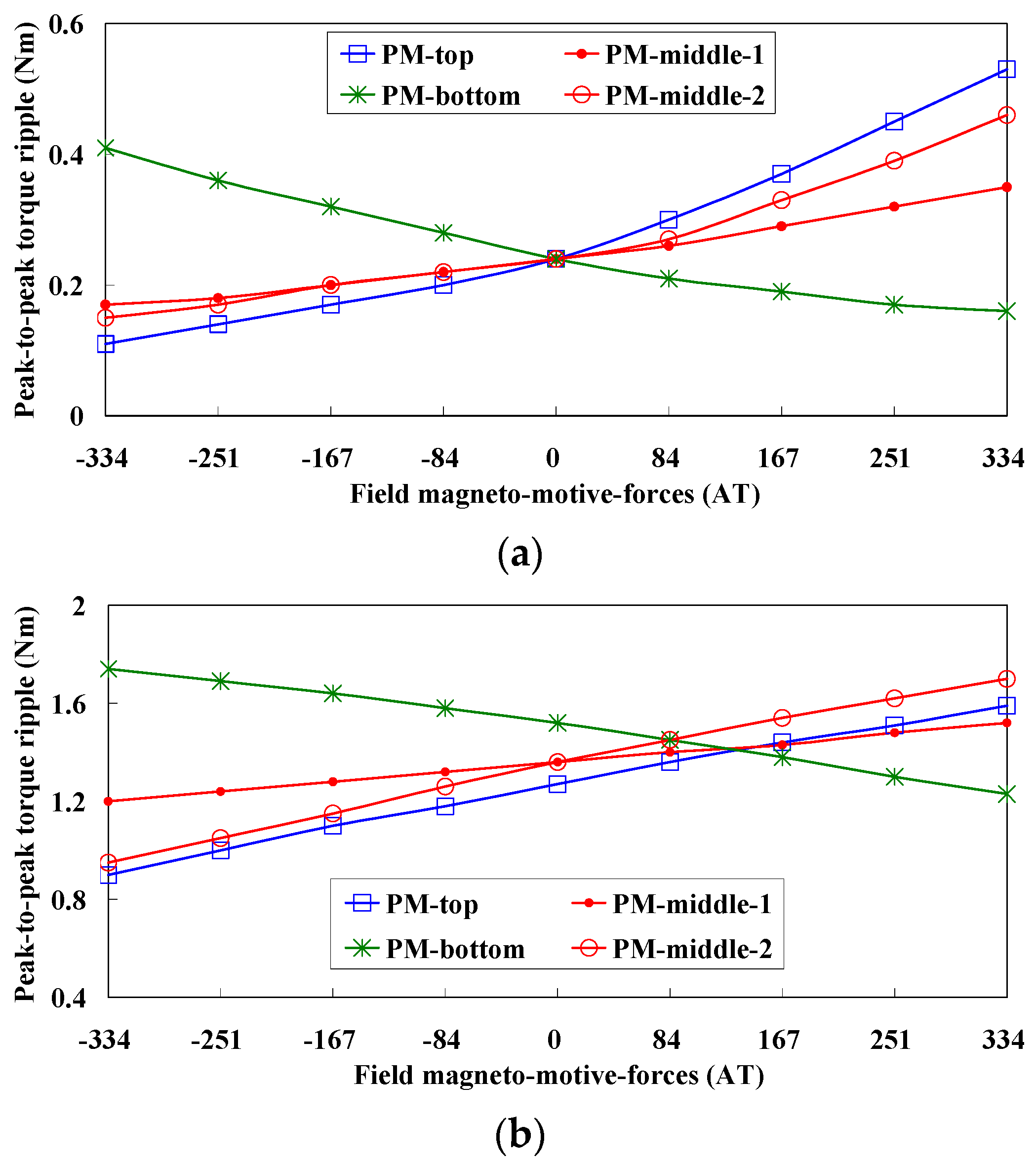
3.2. Electromagnetic Torque
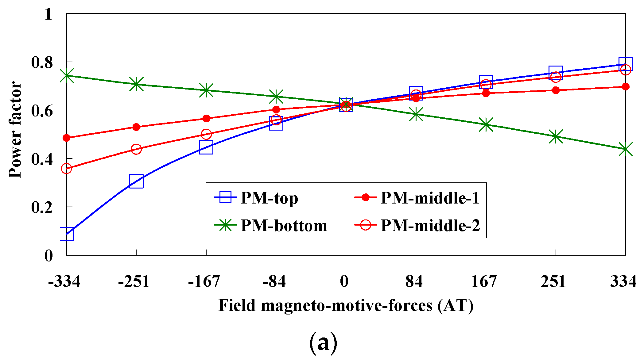
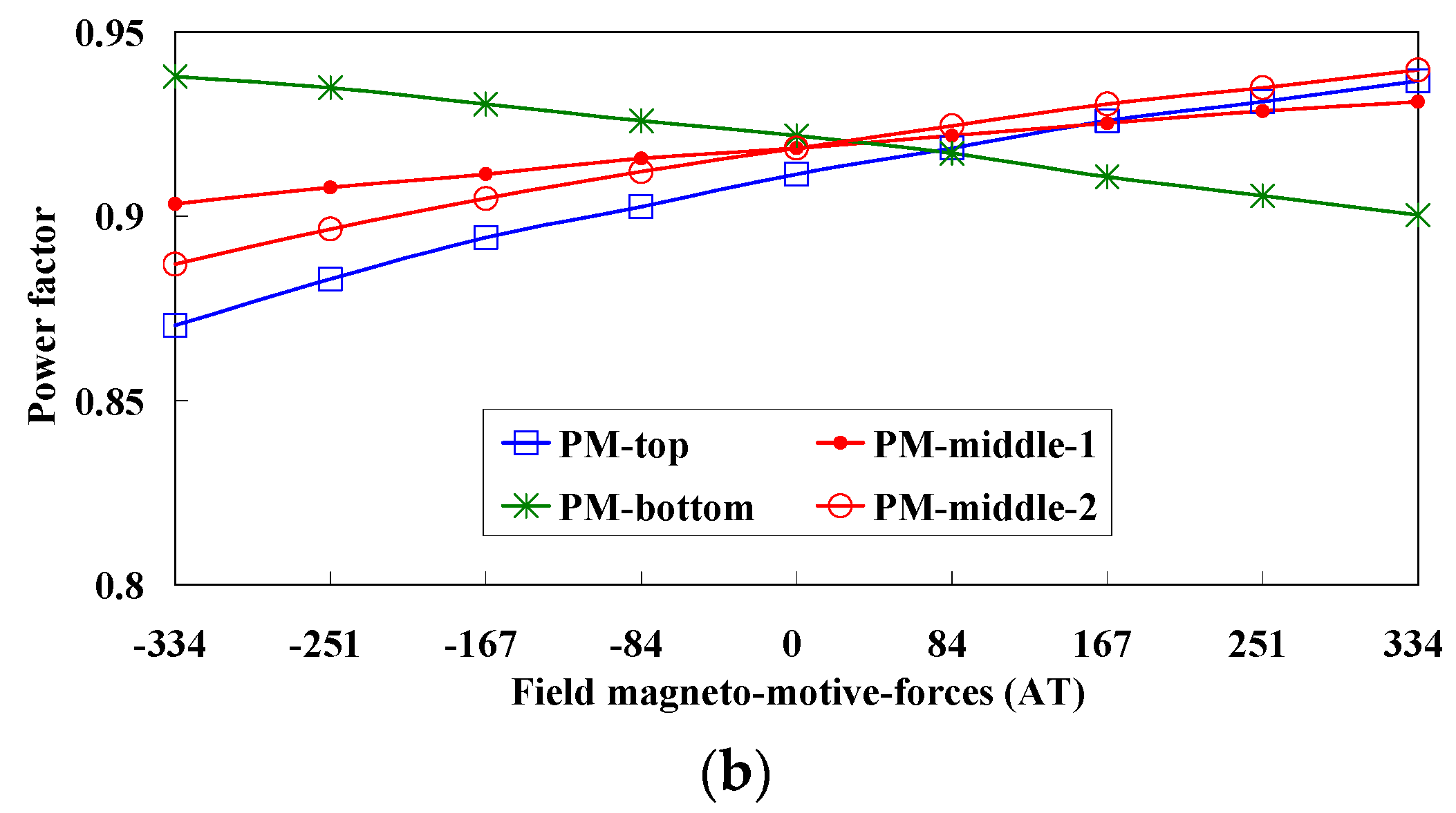
First of all, the flux-linkage equation according to the dq coordinated system and torque evolution equation can be given in Equations (4) and (5), respectively:
[ ψ d ψ q ] = [ L d 0 M s f 0 L q 0 ] [ i d i q i f ] + [ ψ p m 0 ]
T e = 3 2 p r [ i q ψ p m + i d i q ( L d L q ) + M s f i f i q ] = 3 2 P r [ i q ( ψ p m M s f i f ) + i d i q ( L d L q ) ]
where, ψd, ψq and ψpm are d-axis, q-axis and phase PM flux-linkage respectively; Ld, Lq, and Msf are the d-axis and q-axis armature inductances, and the mutual inductance between the armature and field windings, respectively; id, iq, if, pr and Te are d-axis current, q-axis current, field current, number of electromagnetic pole-pairs and electromagnetic torque. Under id = 0 control, Te can be expressed as:
T e = 3 2 P r [ i q ( ψ p m M s f i f ) ] = 3 2 P r i q ( ψ p m ψ f i e l d )
where, ψfield can be considered as the field-excited flux-linkages. The averaged electromagnetic torque values in each HEFS machine are given in Figure 7, along with the torque ripple values given in Figure 8. Compared to the phase-A EMFs, the torque output is more sensitive to the field excitations, especially when ferrite is employed. When NdFeB is employed, the PM-top machine exhibits weakest/worst torque capability, thus the lowest torque density and magnet utilization. Also, the electromagnetic torque is slightly reduced by PFC due to the over-saturated effect. It should be emphasized that, the electromagnetic torque of the corresponding FSPM machines with the same armature currents is 3.5 Nm (with ferrite) and 5.2 Nm (with NdFeB), respectively. The variations of torque ripples given in Figure 8 are similar to those of the average torques, except for the PM-top one when adopting NdFeB. Since in the PM-top topology, the armature flux-linkages are related to the over-saturated effect, meanwhile the torque ripples are more related to air-gap flux density distributions, which are normally regulated by field currents. More details about the air-gap flux-densities can be found in [19,22].

3.3. Power Factor

Power factor is a key factor to the drive-system. By neglecting Rphiq, the power factor can be obtained directly by cosθ. As can be seen in Figure 9, the power factor of the PM-top machine drops greatly with the increase of NFC when ferrite is employed, which can be attributed to a relatively strong armature reaction field and a weak PM excitation field. However, when NdFeB is employed, the power factors in each HEFS machine are much better, i.e., from 0.87 to 0.93.

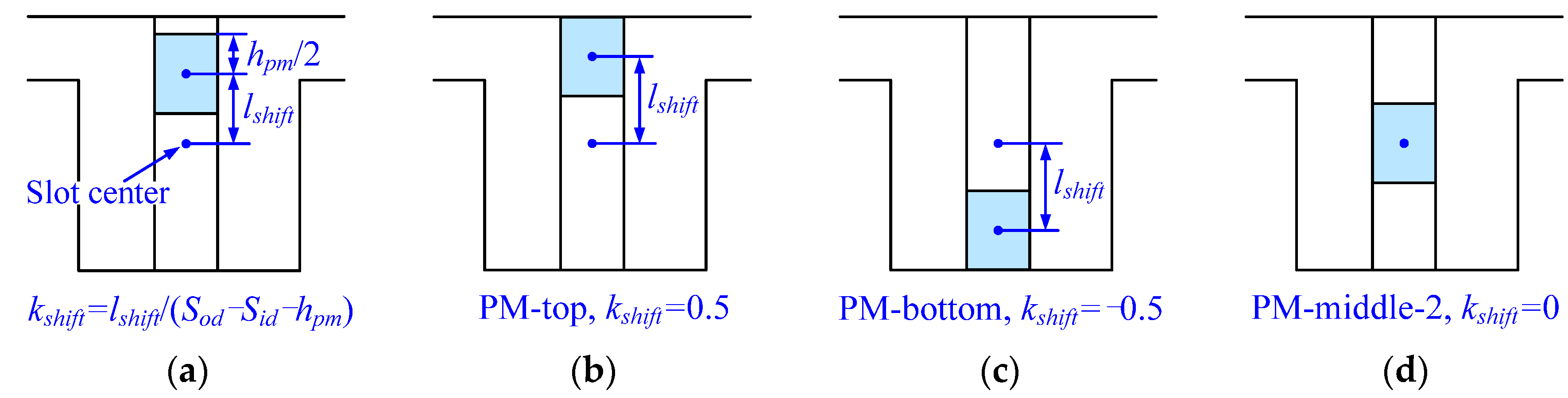
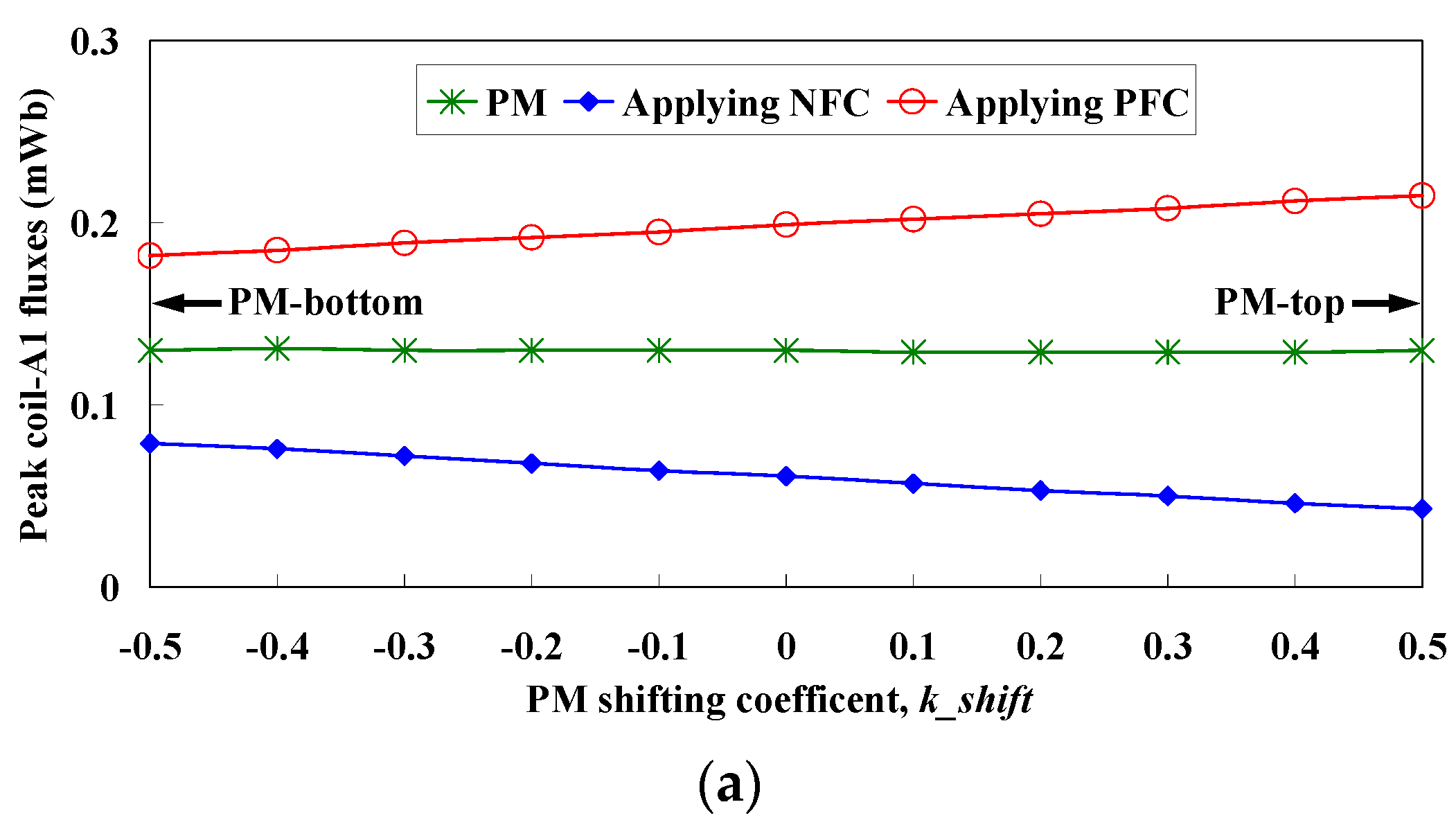
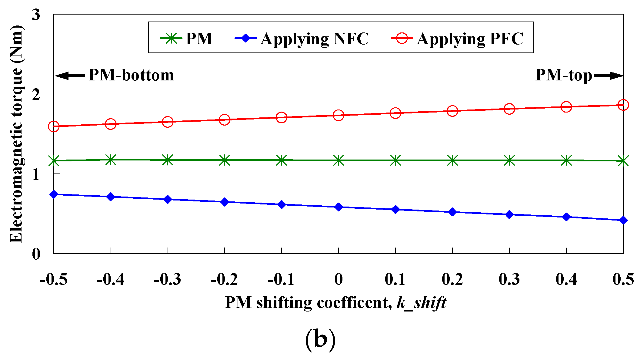
4. Influences of Different PM Positions in the PM-Middle-2 Machine

In the PM-middle-2 machine, the PMs can be shifted along radial direction in the slot, noticing that the field currents neighboring one magnet are in the same direction. This provides greater flexibilities during designing stage for other considerations, e.g., to obtain better thermal dissipation and easier manufacturing process. First of all, the shifting coefficient kshift is defined in Figure 10 by:
k s h i f t = l s h i f t S o d S i d h p m
Apparently, kshift = 0 indicates the original PM-middle-2 machine; kshift = 0.5 indicates the PM-top machine; and kshift = −0.5 indicates the PM-bottom machine, respectively. The influences of kshift on electromagnetic performances are given in Figure 11 and Figure 12, where positive field current (PFC) indicates 8A/mm2 and negative field current (NFC) indicates −8A/mm2 with a slot fill factor of 0.5. Generally, when ferrite is employed, better flux-regulation results can be obtained when PM is moved from bottom towards top, meanwhile the PM-excited torque maintains the same. When NdFeB is employed, both the flux-regulation capability and PM-excited torque drop greatly with the increase of kshift.
Figure 10. Illustration of the PM shifting in the PM-middle-2 machine. (a) Definition of shifting coefficient kshift; (b) Equivalent to PM-top topology when kshift = 0.5; (c) Equivalent to PM-bottom topology when kshift = −0.5; (d) PM-middle-2 topology when kshift = 0.
Energies 08 12351 g010
Figure 11. Influences of kshift when Ferrite is adopted (PFC and NFC indicate positive field current and negative field current, respectively). (a) Variation of no-load coil-A1 flux; (b) Variation of torque values when RMS 98AT per half armature slot is applied.
Energies 08 12351 g011aEnergies 08 12351 g011b
Figure 12. Influences of kshift when NdFeB is adopted (PFC and NFC indicate positive field current and negative field current, respectively). (a) Variation of no-load coil-A1 flux; (b) Variation of torque values when RMS 98AT per half armature slot is applied.
Energies 08 12351 g012

5. Thermal Dissipation

For the HEFS machines, the heat due to copper loss and iron loss are easier to dissipate since both permanent magnets and armature windings are located on the stator, which especially facilitates the accommodation of a water-cooling system on the stator housing. Meanwhile, the operation conditions of magnets, e.g., NdFeB, are directly related to temperature. Hence, in this section, the thermal/heat dissipations and temperature distributions of the four HEFS machines are discussed based on 3D FEA with the software of JMAG.

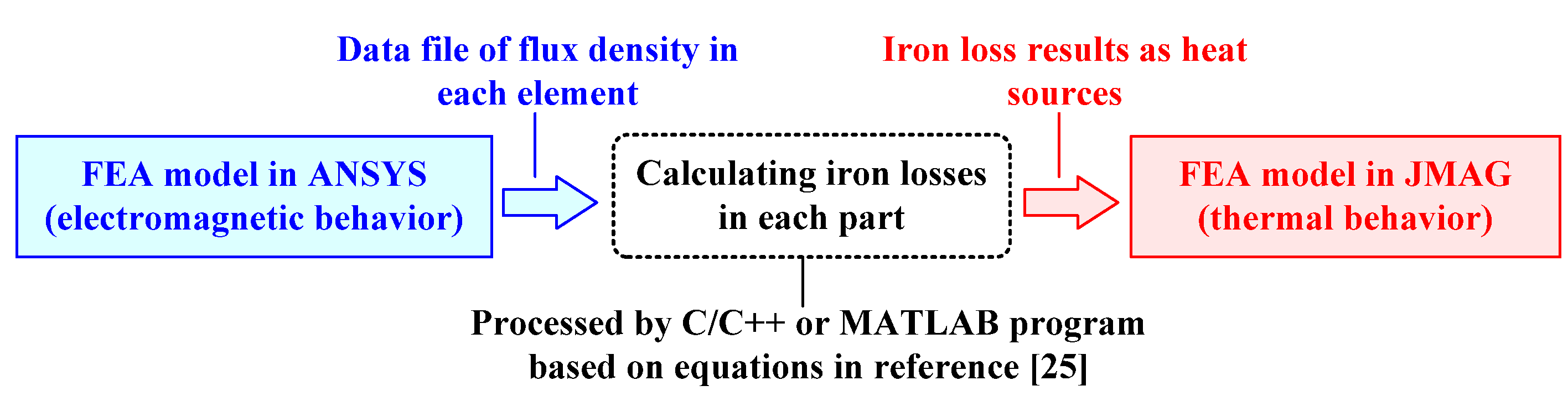
5.1. Copper Loss and Iron Loss

The heat sources can be briefly considered as the sum of copper loss and iron losses, as well as mechanical losses. The copper loss Pcu can be calculated by [23]:
P c u = ρ J R M S 2 V c u
where, ρ (in ohm-meters) is the copper resistivity, JRMS (in amperes per square millimeter) is the RMS current density of armature windings, and Vcu (in cubic meters) is the total copper volume of the armature windings. Amara et al. pointed out that the main advantage of hybrid excitation machines is the additional degree of freedom (DOF) of field currents that they can offer from both design and control points of view, which can be used to optimize the energy consumption of the electric propulsion system [24]. However, the predictions of iron loss in these HEFS machines are much more difficult due to the complex flux density distributions [25,26]. Thus, more attention is paid to thermal/heat dissipations and temperature distributions in this part. The copper loss and iron loss under rated conditions due to PM excitation only are calculated based on ANSYS, and then the temperature related studies are carried out on JMAG. Specifically, firstly, the electromagnetic FEA model of the HEFS machines are built in ANSYS, and the flux density in each element in one electrical period are calculated and exported to data files. Thereafter, based on these data files, the iron losses are calculated using the method introduced in [25]. Finally, the thermal FEA model is built in JMAG, with the obtained copper loss and iron losses applied on the thermal sources. It should be emphasized that, the iron losses are assumed to be evenly distributed in the stator and rotor irons, respectively. Thus, instead of a genuine coupled electromagnetic-thermal fields analysis, the FEA models due to ANSYS and JMAG in this paper are not directly coupled. Figure 13 gives the flow chart to show how the analysis of electromagnetic and thermal behaviors are carried out. The data files are relatively large (in this case, nearly 230 MB in total) since they cover the flux density and area of each element in one electric period, thus the calculation of iron losses is usually processed by a C/C++ or MATLAB program.
Figure 13. Flow chart of the analysis of electromagnetic and thermal behaviors, as well as relationship between different software.
Energies 08 12351 g013

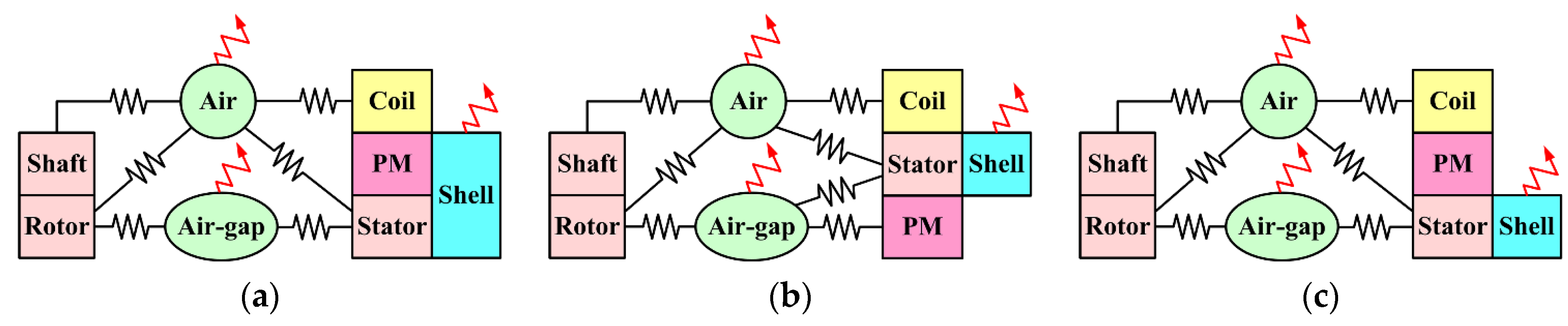
5.2. Heat Equivalent Circuit

First of all, the simplified heat equivalent circuits and thermal properties of materials under ideal conditions are given in Figure 14 and Table 3, respectively. It should be emphasized that the thermal conductivity of coils also counts in the air and glue in the armature and field slots. The determinations of thermal parameters are usually complicated and empirical. Since they are influenced by fabricating process such as contact tolerances between different motor parts, variations of glue density, et al. In addition, due to similar heat dissipation conditions, PM-middle-1 and -2 topologies are supposed to have the same equivalent circuit, i.e., “PM-middle” refers to both PM-middle-1 and -2 in this part. Figure 14 reveals how the heat sources and dissipation, as well as boundary conditions are applied on the FEA model in JMAG, e.g., a thermal resistant indicates direct link to heat dissipation, and conjoint rectangles indicate contact boundaries between them. These boundary conditions are applied on the surfaces of different parts on the 3D FEA model [27,28]. Two kinds of heat sources are applied, i.e., the iron losses (36 W in stator and 19 W in rotor) are applied on motor irons, and the copper loss (64 W) is applied in armature coils. More details about the boundary conditions between theory analysis and applications in JAMG can be found in [28,29]. As can be seen, the best heat dissipation of PMs is expected to be found in the PM-top one, since the magnets directly contact with the shell/housing. Meanwhile, the worst case is expected in the PM-middle and -bottom ones, since the PMs are surrounded by both stator iron and armature coils, which unfortunately carry the main heat sources.
Figure 14. Configuration of the heat equivalent circuits for four HEFS machines. (a) PM-top; (b) PM-bottom; (c) PM-middle-1&-2.
Energies 08 12351 g014
Table 3. Thermal and mechanical properties of different materials.
Machine PartsThermal ConductivitiesMechanical Properties
Stator core23 W/m·°C7650 kg/m3
Rotor core23 W/m·°C7650 kg/m3
Shaft80 W/m·°C7800 kg/m3
Stator shell237 W/m·°C2688 kg/m3
Coil340 W/m·°C4000 kg/m3
Water0.62 W/m·°C1000 kg/m3
Ambient air0.30 W/m·°C1.22 kg/m3

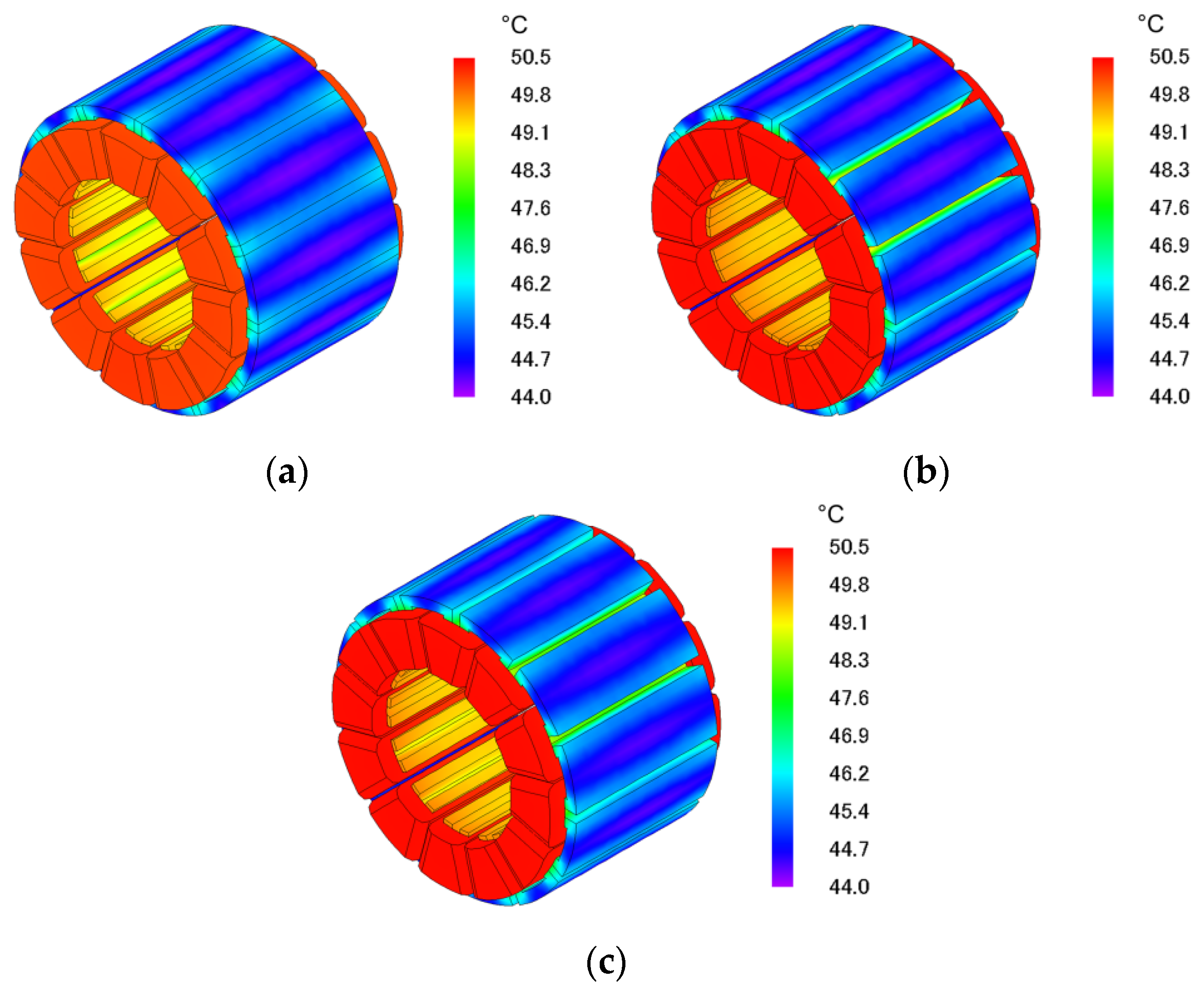
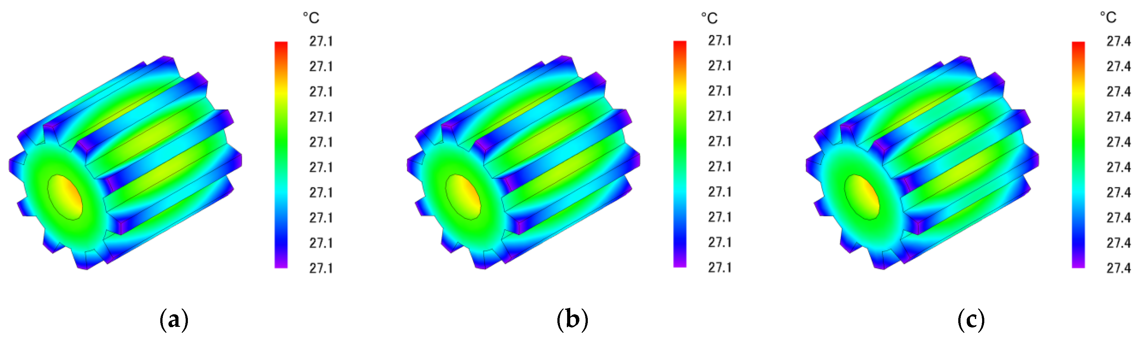
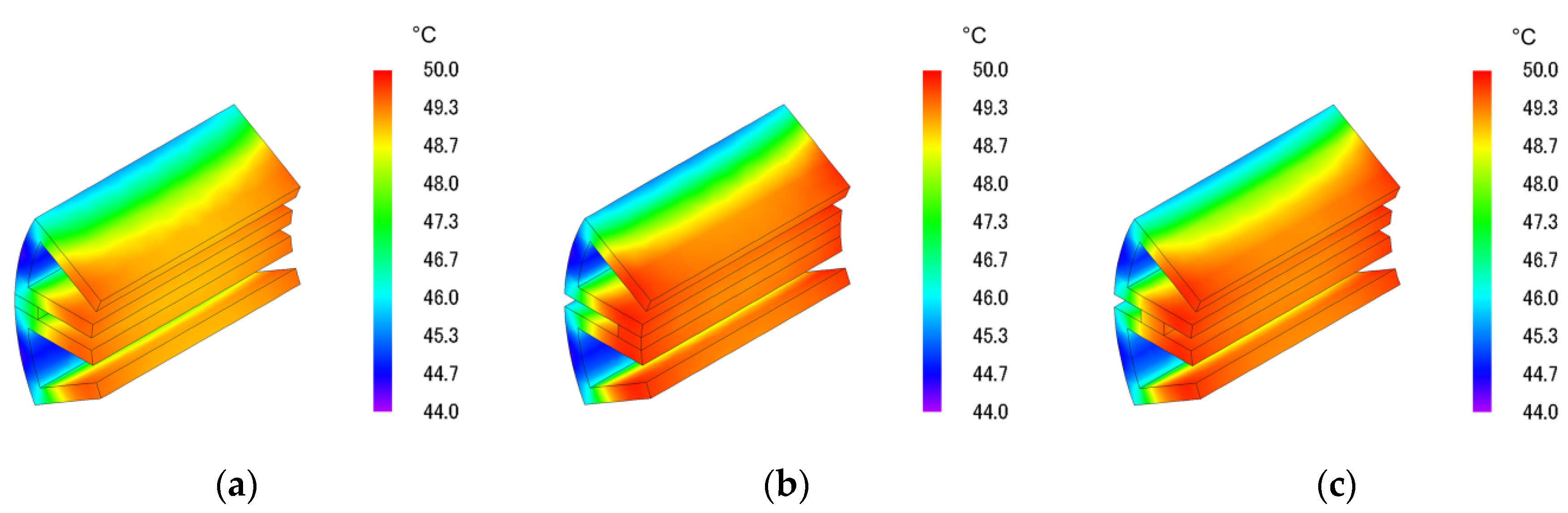
5.3. Steady-State Temperature Distributions with NdFeB

Based on the FEA-models built above, the steady-state temperature distributions under rated operation due to only PM excitation (by NdFeB) are predicted by JMAG (ambient temperature is set 25 °C). The 3D FEA results are shown in Figure 15 and Figure 16. Overall, the temperatures conditions of these HEFS topologies are very close. Obviously, the maximum and minimum values can be found in coils and stator outer surface, respectively, but it should be noted that the temperature in magnets differ greatly, more details of which are to be revealed in the following part.
Figure 15. Temperature distributions in stator, when NdFeB is employed. (a) PM-top; (b) PM-bottom; (c) PM-middle-1&-2.
Energies 08 12351 g015
Figure 16. Temperature distributions in rotor, when NdFeB is employed. (a) PM-top; (b) PM-bottom; (c) PM-middle-1&-2.
Energies 08 12351 g016

5.4. Influence of Temperature on Magnets

When NdFeB is employed, the temperature directly relates to PM demagnetization, especial in PM-middle and -bottom machines, where the magnets are surrounded by armature windings. For example, in the linear part of the B-H curve, for temperature below about 100 °C, the remanence Br and coercive force Hc of magnets vary linearly versus temperature, which can be expressed as [30,31]:
B r = B r A + s b ( T T A )
H c = H c A + s c ( T T A )
where, BrA and HcA are the remanence and coercive force at normal ambient temperature TA, and sb and sc are the slope of Br- and Hc- temperature characteristics, respectively. The typical values of sb and sc for NdFeB magnets applied in this paper are −0.11%/°C and −0.62%/°C, respectively, so it is necessary to pay attention to the temperature variations in stator core, and, especially magnets, in order to predict the machine parameters more accurately. Typically, the temperature sensors are placed on the surface of the stator iron, therefore, it is crucial to determine the temperature distributions and hot spot locations inside the machine, and consequently present a rational design for the cooling system in order to reduce the temperature rising and keep it in the permitted range. Figure 17 and Figure 18 give the detailed temperature distributions in stator irons and magnets. As expected, the PMs obtain better heat dissipation situation when near the machine shell, i.e., the PM-Top topology provides the best heat condition for the magnets. Since the hybrid-excited machine are designed to cover most of the working time by only PM excitation, the thermal behaviors when field currents are applied are briefly mentioned in Table 4. The corresponding copper loss in field windings are 42.2 W. As can be seen, different temperatures can be found when PFC and NFC is applied, respectively, due to slightly different iron losses. It should be noticed that, the temperatures under hybrid conditions are steady-state values, while in practice, the field currents are usually applied in short-term.
Figure 17. Temperature distributions in stator iron and magnet when NdFeB is employed. (a) PM-top; (b) PM-bottom; (c) PM-middle-1&-2.
Energies 08 12351 g017
Figure 18. Temperature distributions in the magnet when NdFeB is employed. (a) PM-top; (b) PM-bottom; (c) PM-middle-1&-2.
Energies 08 12351 g018
Table 4. Typical temperature values in PMs when NdFeB is employed.
ExcitationValuesPM-TopPM-BottomPM-Middle-1 & 2
Only PMMinimum45.4 °C49.2 °C47.9 °C
Maximum47.8 °C49.8 °C49.6 °C
PM&PFCMinimum59.1 °C65.2 °C67.3 °C
Maximum62.6 °C66.3 °C69.1 °C
PM&NFCMinimum58.1 °C63.2 °C66.5 °C
Maximum61.3 °C66.1 °C68.4 °C
Overall, considering that the PM-bottom topology exhibits best flux-regulation and torque output capabilities as analyzed in Section 3 and Section 4, hence, it is a contradiction between heat dissipation and electromagnetic performances when NdFeB is employed.
Similarly, Table 5 gives the temperature values in PMs when ferrite is employed, with the heat sources given in Table 6 (variation of iron losses by different excitation conditions are very slight and thus neglected). It should be mentioned that a temperature raise may result in a lower Br and higher Hc values for ferrite PMs.
Table 5. Typical temperature values in PMs when ferrite is employed.
ExcitationValuesPM-TopPM-BottomPM-Middle-1 & 2
Only PMMinimum40.4 °C44.2 °C42.3 °C
Maximum42.4 °C45.8 °C44.1 °C
PM&PFCMinimum53.1 °C60.1 °C62.0 °C
Maximum57.1 °C62.3 °C64.2 °C
PM&NFCMinimum53.2 °C58.1 °C61.6 °C
Maximum55.8 °C60.9 °C63.3 °C
Table 6. Heat sources when ferrite is employed.
Heat SourcePM-TopPM-BottomPM-Middle-1 & 2
Iron losses in stator5.2 W5.2 W5.2 W
Iron losses in rotor1.4 W1.4 W1.4 W
Copper loss in armature64 W64 W64 W
Copper loss in field winding42.2 W42.2 W42.2 W

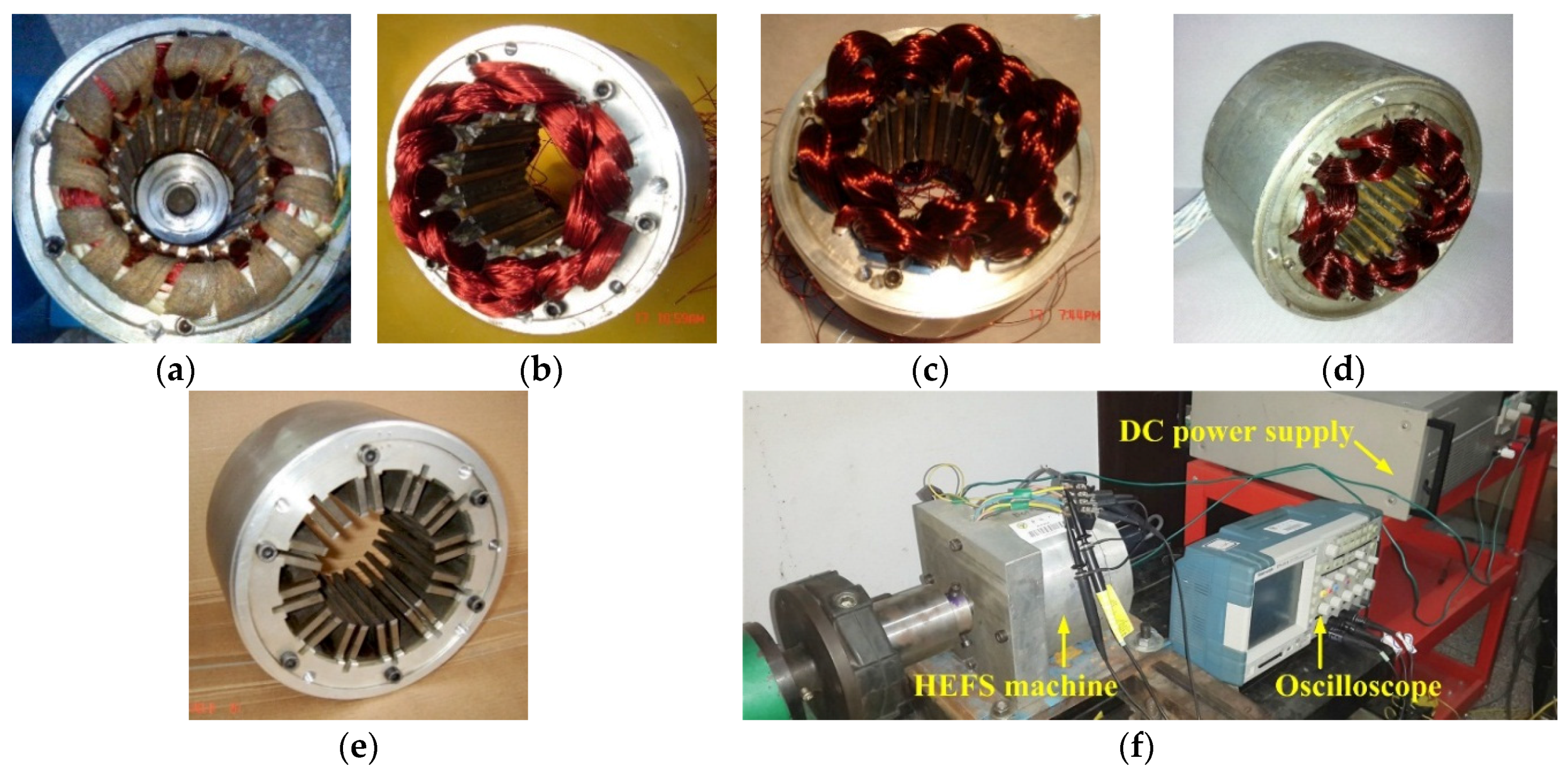
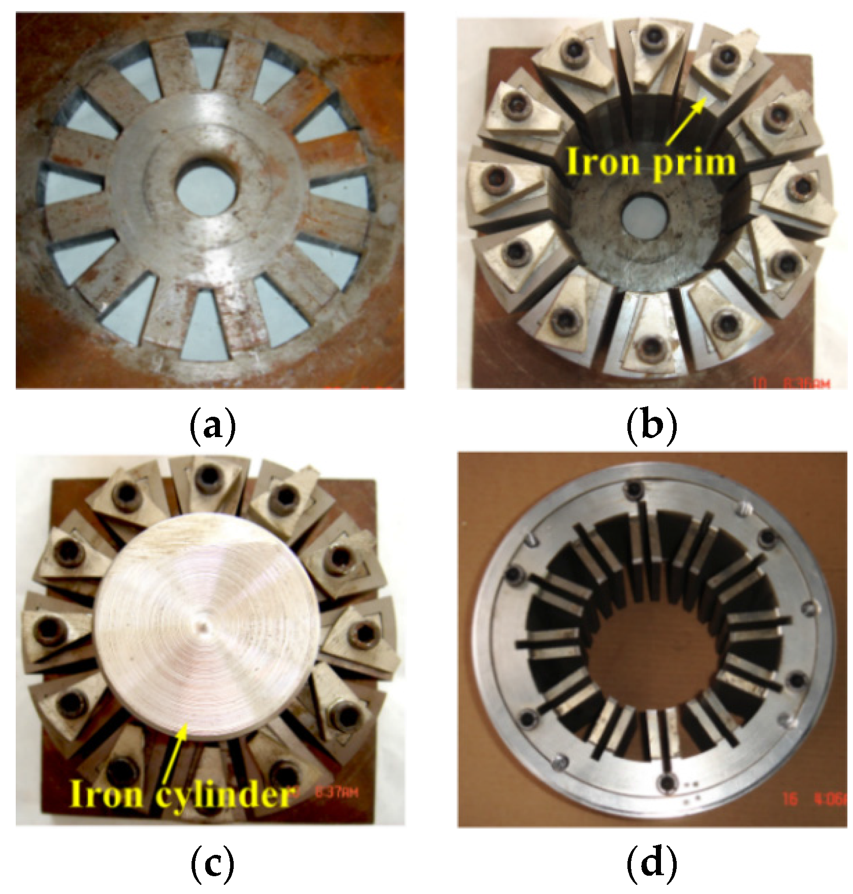
6. Experimental Validations

To further validate the FEA analysis above, prototypes of the four HEFS machines employing NdFeB are manufactured. Figure 18a–e give the stators and housing of each prototype, and Figure 19f shows the experimental platform, in which the field current is supplied by a DC power source. It should be noticed that the PM locations play an important role in manufacturing difficulties and accuracies. The mounting process of stator laminations are shown in Figure 20 [19]. Firstly, 12 iron prims are located at the slots of the assistant base, and the stator laminations are posed on the prims, as shown in Figure 20a,b. Then an iron cylinder with diameter of Sid is used to ensure the lamination concentricity, as shown in Figure 20c. Finally, the prims and iron cylinder are removed after the laminations were glued to the housing, as shown in Figure 20d. More details of the assembly process, as well as introduction of the iron bridges can be found in [19], which also pointed out the PM-Top topology will facilitate the assembling accuracy since the PMs can be located before the stator laminations were glued to the housing. The 3D FEA predicted (by ANSYS) and measured no-load phase-A back-EMF waveforms are compared in Figure 21. Then, the regulations of no-loaded phase-A EMFs and loaded torque values are compared in Figure 22. The experimental no-load torque values (most due to mechanical loss) are counted in the measured results. Table 7 lists the dq-axis inductances. Overall, satisfied agreements are achieved between FEA predictions and experimental measurements, considering manufacturing tolerances.
Figure 19. HEFS machine prototypes and experimental platform. (a) Stator of PM-top machine; (b) Stator of PM-bottom machine; (c) Stator of PM-middle-1 machine; (d) Stator of PM-middle-2 machine; (e) Stator iron and housing; (f) Experimental platform and instruments.
Energies 08 12351 g019
Figure 20. Mounting process of the C-core stator laminations. (a) Assistant base; (b) Locating of laminations; (c) Concentricity of laminations; (d) Accomplished assembling of stator laminations and housing.
Energies 08 12351 g020
Figure 21. 3D FEA predicted and measured no-load phase-A back-EMF waveforms due to PMs only, at 1500 r/min. (a) PM-top and -bottom; (b) PM-middle-1 and -2.
Energies 08 12351 g021
Figure 22. Comparisons of the regulation results by different field currents. (a) No-load RMS phase-A EMF values at 1500 r/min; (b) Average torque values when RMS 285 AT is applied in half armature slot.
Energies 08 12351 g022
Table 7. Comparison of The 3D FEA calculated and measured dq-axis inductances.
ItemPM-TopPM-BottomPM-Middle-1PM-Middle-2
Ld, FEA19.4 mH25.3 mH24.8 mH24.8 mH
Ld, measured18.6 mH24.2 mH23.8 mH23.3 mH
Error (%)4.1%4.3%4.0%6.0%
Lq, FEA16.7 mH28.0 mH25.1 mH25.1 mH
Lq, measured16.1 mH27.0 mH23.9 mH24.2 mH
Error (%)3.6%3.6%4.8%3.6%

7. Conclusions

In this paper, based on both 2D and 3D FEA methods, the steady-state characteristics of four HEFS machines with different magnet locations (namely PM-top, PM-bottom, PM-middle-1 and -middle-2 HEFS machines, respectively) and different materials (namely ferrite and NdFeB) are comprehensively evaluated and compared. Both the no-load and loaded conditions are covered with more attention paid to flux-regulation capabilities and thermal behaviors. Overall, the PM-top and -bottom topologies exhibit reversal flux-regulation functions. The PM-middle-1 topology shows worst flux-regulation capability since it can be considered as a combination of PM-top and -bottom ones. Then the PM-middle-2 one was obtained to enhance the flux-regulation capability of the PM-middle-1 topology. The comprehensive evaluations of these HEFS machines are summarized in Table 8 and quantitatively listed in Table 9 (without considering the PM-middle-1 HEFS machine). Take torque ripple (using NdFeB) for example, Tr-top:Tr-bottom:Tr-middle-2 = 0.94:1.18:1.0, where Tr-top, Tr-bottom, and Tr-middle-2 are the torque ripple values of the PM-top, -bottom, and -middle-2 machines, respectively. The following conclusions can be derived:
(1)
When ferrite is employed, the PM-top HEFS machine shows best PM utilization, flux-regulation capability, along with best thermal condition of PMs, thus the overall greatest potential in low-cost applications.
(2)
When NdFeB is employed, the PM-bottom HEFS machine exhibits best PM utilization, flux-regulation and torque output capabilities, as well as best THD contents in phase EMFS waveform, only with the drawback of slightly unsatisfied thermal condition of PMs. Overall, the PM-bottom one shows best potential in applications when NdFeB is used.
It is worth mentioned that, although this paper gives a comprehensive comparison of the HEFS machines with identical U-shaped stator laminations, studies of the noise/vibration behavior, as well as efficiency analysis and advanced control strategies are not covered, which can be considered as the future work on these HEFS machines.
Table 8. Comprehensive evaluations.
PerformanceAdopting FerriteAdopting NdFeB
-Top-Bottom-Middle-2-Top-Bottom-Middle-2
PM utilizationOOO×O
Flux regulation capabilityO××O
PM torque outputOOO×O
Torque rippleOOO×O
THD of no-load phase EMF×O×O
3D end-effectOOOOOO
Thermal condition of PMs///××
O indicates the average level; √ indicates better than average; × indicates worse than average.
Table 9. Quantitative evaluations in per-unit/proportion form.
PerformanceAdopting FerriteAdopting NdFeB
-Top-Bottom-Middle-2-Top-Bottom-Middle-2
PM utilization1.01.01.00.561.121.0
Flux regulation capability1.11.00.60.121.351.0
PM torque output1.01.01.00.561.121.0
Torque ripple1.01.01.00.941.181.0
THD of no-load phase EMF1.050.951.01.520.861.0
3D end-effect1.01.01.01.01.01.0
Thermal condition of PMs1.111.01.0

Acknowledgments

This work was supported by 973 Program of China (2013CB035603), National Natural Science Foundation of China (51177013, 51322705), Technology R&D Program of Jiangsu Province (BE2013880, BY2012195), “333 Talents Project” of Jiangsu Province, Postgraduate Research and Innovation Project of University in Jiangsu Province under Project (CXZZ12_0104).

Author Contributions

All authors contributed to this work by collaboration. Gan Zhang and Wei Hua designed the HEFS machines and carried out the analysis of the flux-regulating functions, thermal behaviors, as well as the experiments. The whole project was supervised by Ming Cheng.

Conflicts of Interest

The authors declare no conflict of interest.

References

  1. Rauch, S.E.; Johnson, L.J. Design principles of flux-switching alternators. AIEE Trans. Power Appar. Syst. 1955, 74, 1261–1268. [Google Scholar]
  2. Hoang, E.; Ben-Ahmed, A.H.; Lucidarme, J. Switching flux permanent magnet polyphased synchronous machines. In Proceedings of the 7th Europe Conference on Power Electronics and Applications, Trondheim, Norway, 8–10 September 1997; pp. 903–908.
  3. Zulu, A.; Mecrow, B.C.; Armstrong, M. Permanent-magnet flux-switching synchronous motor employing a segmental rotor. IEEE Trans. Ind. Appl. 2012, 48, 2259–2267. [Google Scholar] [CrossRef]
  4. Deodhar, R.P.; Pride, A.; Iwasaki, S.; Bremner, J.J. Performance improvement in flux-switching PM machines using flux diverters. IEEE Trans. Ind. Appl. 2014, 50, 973–978. [Google Scholar] [CrossRef]
  5. Hua, W.; Cheng, M.; Zhu, Z.Q.; Howe, D. Analysis and optimization of back-EMF waveform of a flux-switching permanent magnet motor. IEEE Trans. Energy Convers. 2008, 23, 727–733. [Google Scholar] [CrossRef]
  6. Zhu, Z.Q.; Chen, J.T. Advanced flux-switching permanent magnet brushless machines. IEEE Trans. Magn. 2010, 46, 1447–1453. [Google Scholar] [CrossRef]
  7. Chau, K.T.; Chan, C.C.; Liu, C. Overview of permanent-magnet brushless drives for electric and hybrid electric vehicles. IEEE Trans. Ind. Electron. 2008, 5, 2246–2257. [Google Scholar] [CrossRef] [Green Version]
  8. Zhao, W.X.; Cheng, M.; Chau, K.T.; Cao, R.W.; Ji, J.H. Remedial injected-harmonic-current operation of redundant flux-switching permanent-magnet motor drives. IEEE Trans. Ind. Electron. 2013, 60, 151–159. [Google Scholar] [CrossRef] [Green Version]
  9. Yan, J.H.; Lin, H.Y.; Zhu, Z.Q.; Jin, P.; Guo, Y.J. Cogging torque optimization of flux-switching transverse flux permanent magnet machine. IEEE Trans. Magn. 2013, 49, 2169–2172. [Google Scholar] [CrossRef]
  10. Wang, D.H.; Wang, X.H.; Jung, S.Y. Reduction on cogging torque in flux-switching permanent magnet machine by teeth notching schemes. IEEE Trans. Appl. 2012, 48, 4228–4231. [Google Scholar] [CrossRef]
  11. Zhao, J.; Yan, Y.S.; Li, B.; Liu, X.D.; Chen, Z. Influence of different rotor teeth shapes on the performance of flux switching permanent magnet machines used for electric vehicles. Energies 2014, 7, 8056–8075. [Google Scholar] [CrossRef]
  12. Gaussens, B.; Hoang, E.; Lécrivain, M.; Manfe, P.; Gabsi, M. A hybrid-excited flux-switching machine for high-speed DC-alternator applications. IEEE Trans. Ind. Electron. 2014, 61, 2076–2989. [Google Scholar] [CrossRef]
  13. Wang, Y.; Deng, Z.Q. Hybrid excitation topologies and control strategies of stator permanent magnet machines for DC power system. IEEE Trans. Ind. Electron. 2012, 59, 4601–4616. [Google Scholar] [CrossRef]
  14. Cheng, M.; Hua, W.; Zhang, J.Z.; Zhao, W.X. Overview of stator-permanent magnet brushless machines. IEEE Trans. Ind. Electron. 2011, 58, 5087–5101. [Google Scholar] [CrossRef]
  15. Zhu, Z.Q.; Howe, D. Electrical machines and drives for electric, hybrid, and fuel cell vehicles. IEEE Proc. 2007, 95, 746–765. [Google Scholar] [CrossRef]
  16. Hoang, E.; Lecrivain, M.; Gabsi, M. A new structure of a switching flux synchronous polyphased machine with hybrid excitations. In Proceedings of the 12th European Conference on Power Electronics Applications, Aalborg, Denmark, 2–5 September 2007; pp. 1–8.
  17. Hua, W.; Cheng, M.; Zhang, G. A novel hybrid excitation flux-switching motor for hybrid vehicles. IEEE Trans. Magn. 2009, 45, 4728–4731. [Google Scholar] [CrossRef]
  18. Owen, R.L.; Zhu, Z.Q.; Jewell, G.W. Hybrid excited flux-switching permanent magnet machines. In Proceedings of the 13th European Conference on Power Electronics Applications, Barcelona, Spain, 8–10 September 2009; pp. 1–10.
  19. Hua, W.; Zhang, G.; Cheng, M. Flux-regulation theories and principles of hybrid-excited flux-switching machines. IEEE Trans. Ind. Electron. 2015, 62, 5359–5369. [Google Scholar] [CrossRef]
  20. Zhang, G.; Hua, W.; Cheng, M.; Liao, J.; Wang, K.; Zhang, J. Investigation of an improved hybrid-excitation flux switching brushless machine for HEV/EV applications. IEEE Trans. Ind. Appl. 2015, 51, 3791–3799. [Google Scholar] [CrossRef]
  21. Zhang, G.; Hua, W.; Cheng, M.; Liao, J.; Zhang, J.; Jiang, W. Investigation of on-loaded performances of hybrid-excitation flux-switching brushless machines for HEV/EV applications. In Proceedings of the 2014 IEEE Energy Conversion Congress and Exposition (ECCE), Pittsburgh, PA, USA, 14–18 September 2014; pp. 328–335.
  22. Zhang, G.; Cheng, M.; Hua, W.; Dong, J.N. Analysis of the over-saturated effect in hybrid excited flux-switching machines. IEEE Trans. Magn. 2011, 47, 2827–2830. [Google Scholar] [CrossRef]
  23. Li, G.; Ojeda, J.; Hoang, E.; Gabsi, M.; Lécrivain, M. Thermal-electromagnetic analysis for driving cycles of embedded flux-switching permanent-magnet motors. IEEE Trans. Veh. Technol. 2012, 61, 140–151. [Google Scholar] [CrossRef]
  24. Amara, Y.; Vido, L.; Gabsi, M.; Hoang, E.; Ahmed, A.H.B.; Li, G. Hybrid excitation synchronous machines: Energy-efficient solution for vehicles propulsion. IEEE Trans. Veh. Technol. 2009, 58, 2137–2149. [Google Scholar] [CrossRef]
  25. Pang, Y.; Zhu, Z.Q.; Howe, D.; Iwasaki, S.; Deodhar, R.; Pride, A. Investigation of iron loss in flux-switching PM machines. In Proceedings of the 4th IET Conference on Power Electronics, Machines and Drives (PEMD), York, UK, 2–14 April 2008; pp. 460–464.
  26. Nerg, J.; Rilla, M.; Pyrhonen, J. Thermal analysis of radial-flux electrical machines with a high power density. IEEE Trans. Ind. Electron. 2008, 55, 3543–3554. [Google Scholar] [CrossRef]
  27. JSOL Corporation. JMAG User’s Manual Solver; Version 10; JSOL Corporation: Tokyo, Japan, 2010. [Google Scholar]
  28. JSOL Corporation. JMAG Designer Online Help; Version 10.5; JSOL Corporation: Tokyo, Japan, 2011. [Google Scholar]
  29. Huang, Z.; Nategh, S.; Alakula, M.; Lassila, V.; Yuan, J.L. Direct oil cooling of traction motors in hybrid drives. In Proceedings of the 2012 IEEE International Electric Vehicle Conference (IEVC), Greenville, SC, USA, 4–8 March 2012; pp. 1–8.
  30. Sebastian, T. Temperature effects on torque production and efficiency of PM motors using NdFeB magnets. IEEE Trans. Ind. Appl. 1995, 31, 353–357. [Google Scholar] [CrossRef]
  31. Zhou, P.; Lin, D.; Xiao, Y.; Lambert, N.; Rahman, M.A. Temperature-dependent demagnetization model of permanent magnets for finite element analysis. IEEE Trans. Magn. 2012, 48, 1031–1034. [Google Scholar] [CrossRef]

