
Design and Optimization of Permanent Magnet Brushless Machines for Electric Vehicle Applications


Abstract
:1. Introduction
2. Machine Design Specifications


| Parameters | Values | |
|---|---|---|
| Design specifications | Continuous power Pc (kW) | 5 |
| Continuous torque below and at base speed Tc (Nm) | 40 | |
| Efficiency η (%) | 80–93 | |
| Base speed ωb (rpm) | 1200 | |
| Maximum speed ωmax (rpm) | 5000 | |
| Constant power speed range | 3–4 | |
| Maximum phase voltage Ulim (V) | 74 | |
| Maximum phase current Ilim (A) | 28 | |
| Initial design | Number of slots Ns | 12 |
| Number of pole pairs p | 5 | |
| Stator outer diameter D1 (mm) | 200 | |
| Stator inner diameter Di1 (mm) | 121 | |
| Stack length L (mm) | 79.2 | |
| Number of turns N | 20 | |
3. Optimization of the Constant Power Speed Range
| Design variants | Initial Values | Optimal Values |
|---|---|---|
| Number of turns N | 20 | 24 |
| Stack length L (mm) | 79.2 | 66 |
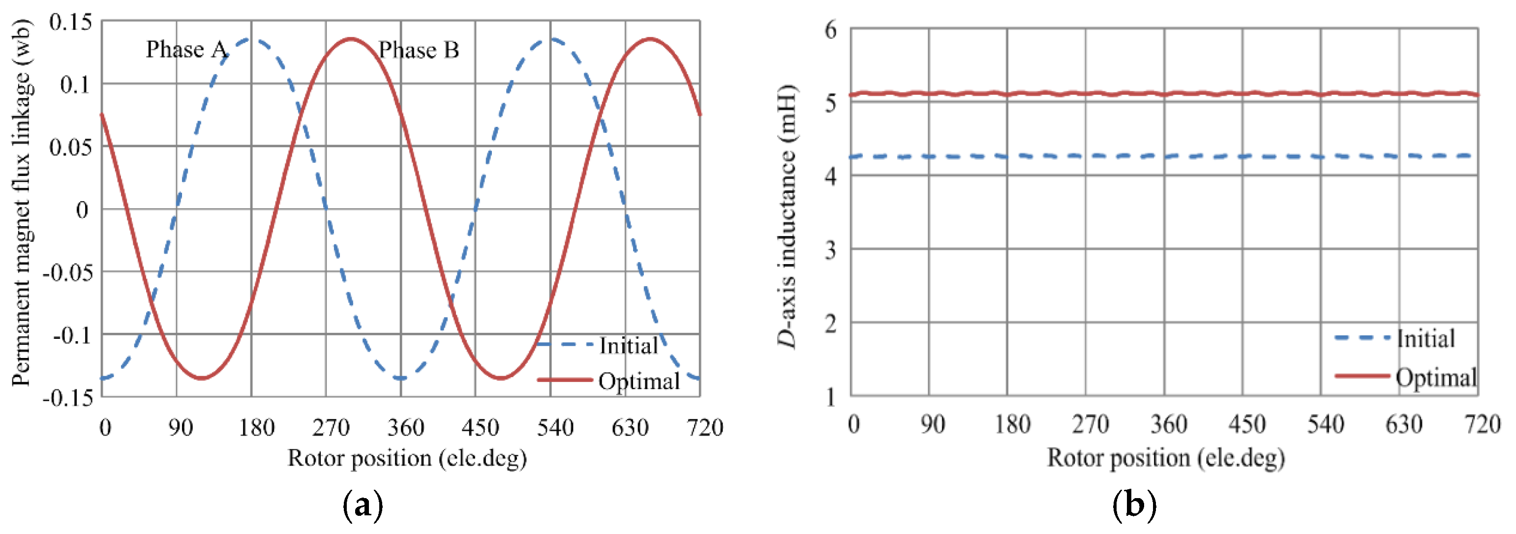
| d-axis inductance Ld (mH) | 4.26 | 5.11 |
| Permanent magnet flux linkage ψf (wb) | 0.14 | 0.14 |
4. Performance Analysis
4.1. Performance Analysis at the Rated Operating Point


| Performances | Initial Machine | Optimal Machine |
|---|---|---|
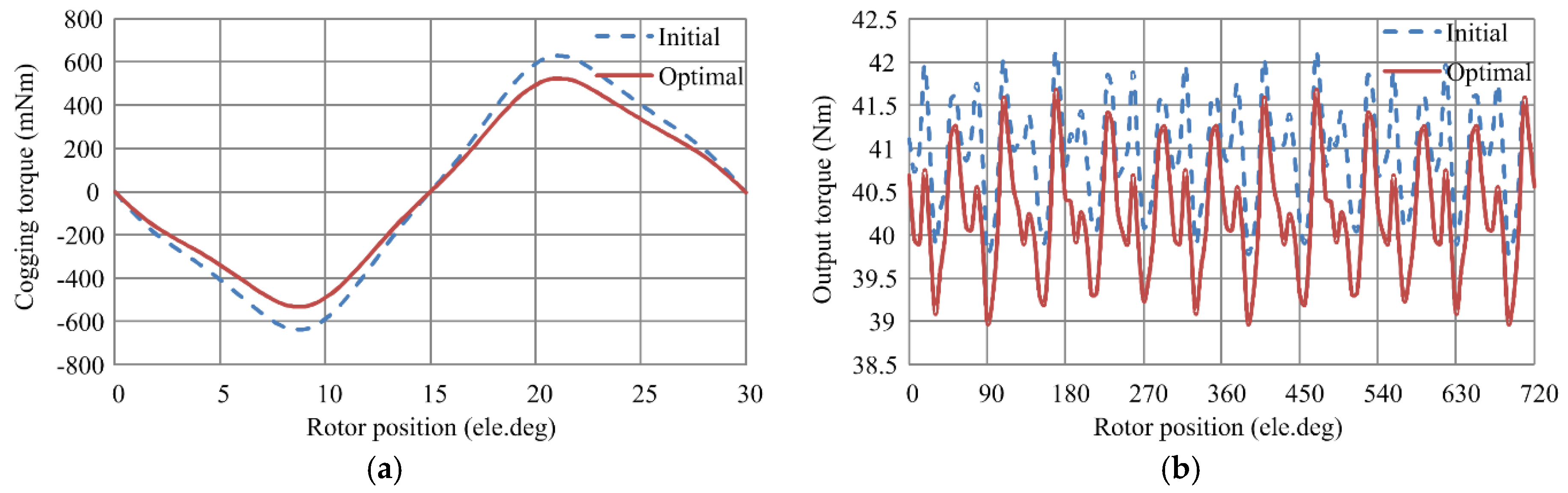
| Torque (Nm) | 40.8 | 40.1 |
| Torque density (kNm/m3) | 18.47 | 21.78 |
| Torque production per unit PM (kNm/mm3) | 4.46 | 5.26 |
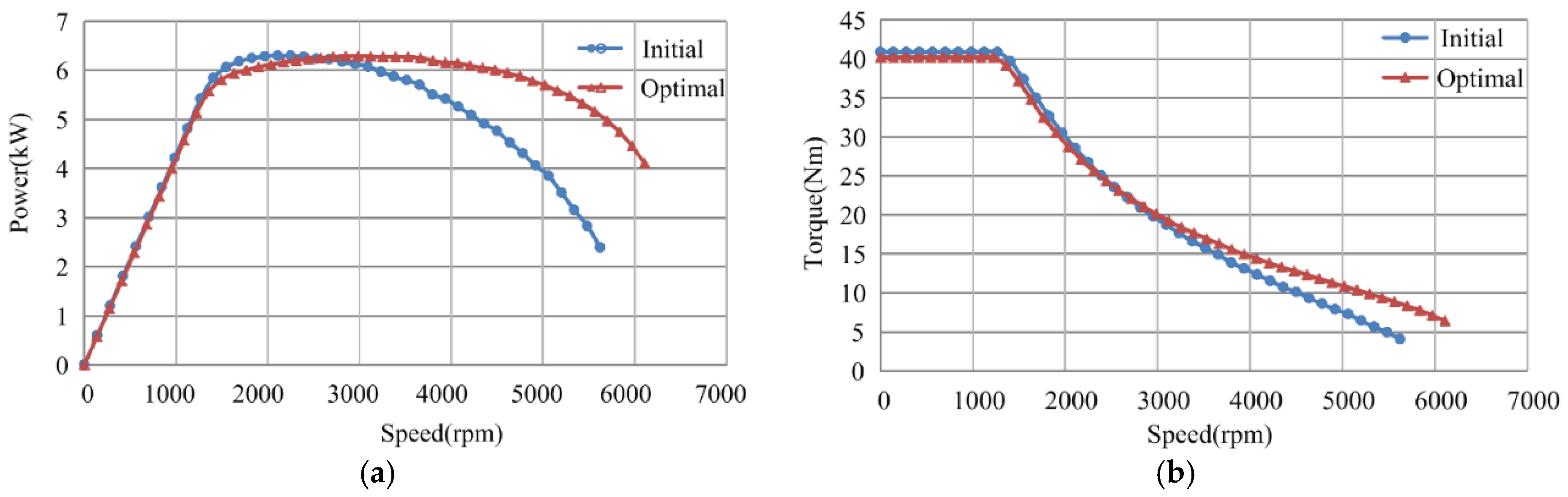
| Power (kW) | 5.1 | 5.0 |
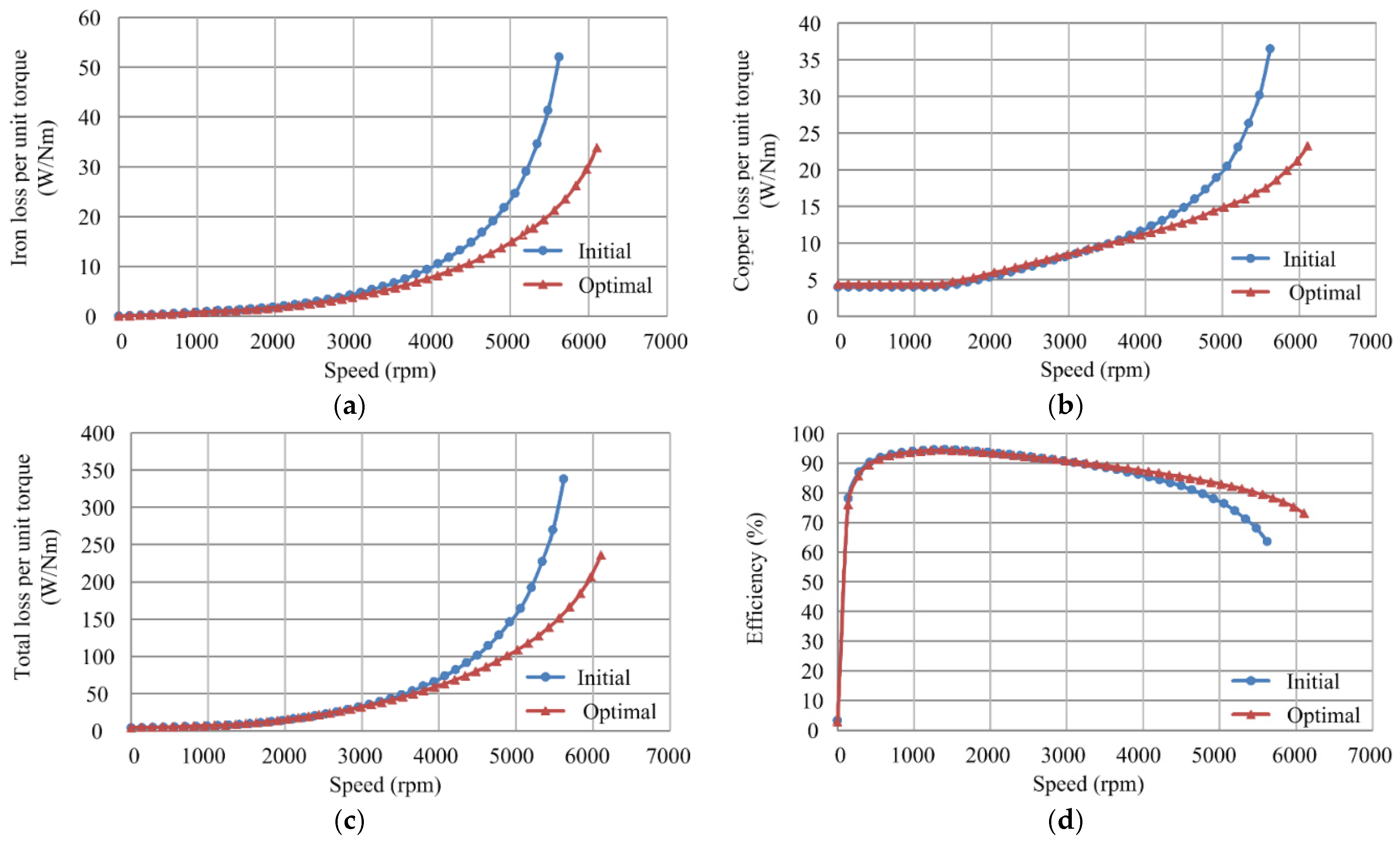
| Iron loss (W) | 43.8 | 38.5 |
| Eddy loss (W) | 13.9 | 17.0 |
| Copper loss (W) | 163.2 | 175.2 |
| Total loss (W) | 320.9 | 330.8 |
| Efficiency (%) | 94.12 | 93.84 |
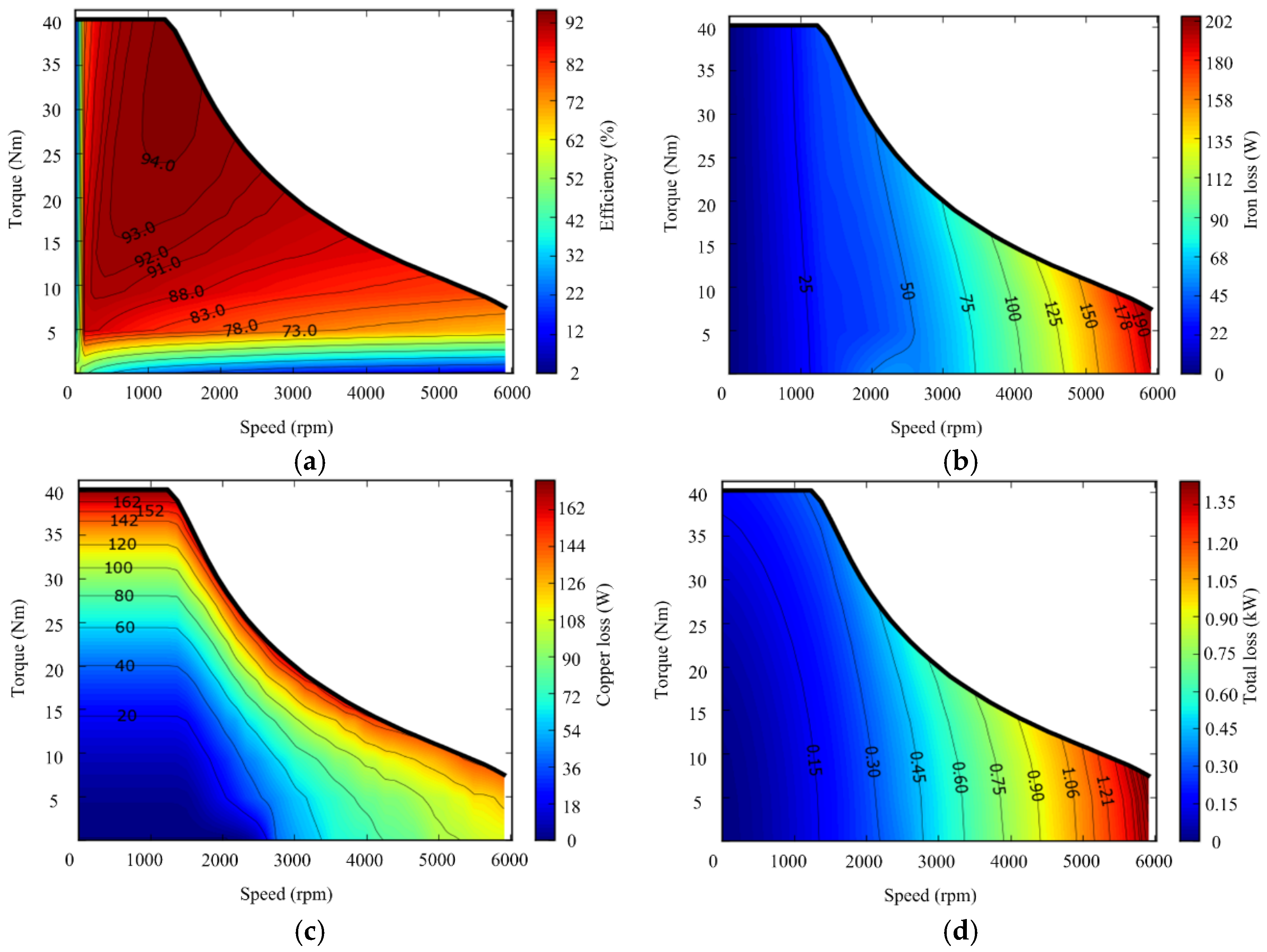
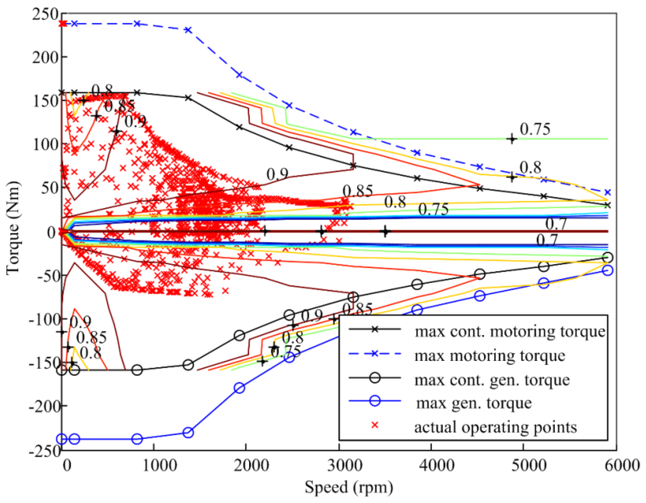
4.2. Performances Analysis over the Speed Range


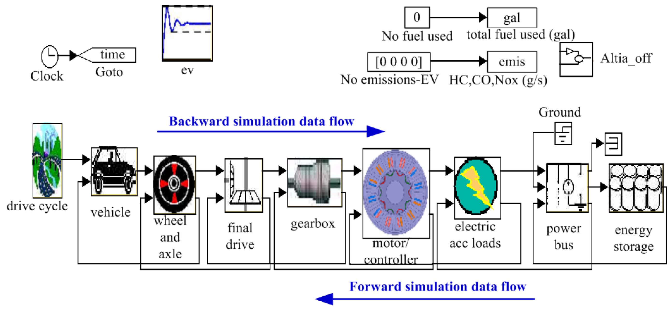
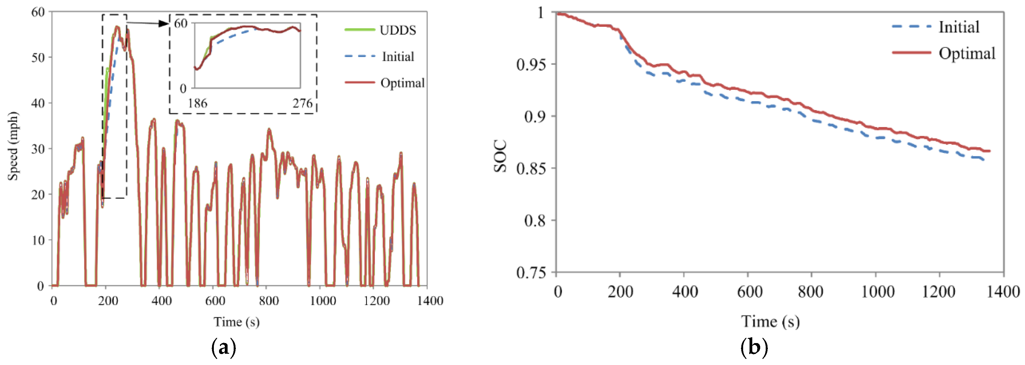
4.3. Performances Comparison over the Urban Dynamometer Driving Schedule


| Performances | Initial Machine | Optimal Machine |
|---|---|---|
| Acceleration time of 0–30 mph (s) | 6.2 | 6.1 |
| Acceleration time of 20–55 mph (s) | 12.7 | 10.6 |
| Acceleration time of 0–55 mph (s) | 34.1 | 24 |
| Maximum acceleration (ft/s2) | 7.2 | 7.9 |
| Maximum speed (mph) | 59.9 | 65.2 |
| Gasoline equivalent (mpg) | 102.9 | 106.7 |

5. Conclusions
Acknowledgments
Author Contributions
Conflicts of Interest
References
- De Santiago, J.; Bernhoff, H.; Ekergard, B.; Eriksson, S.; Ferhatovic, S.; Waters, R.; Leijon, M. Electrical motor drivelines in commercial all-electric vehicles: A review. IEEE Trans. Veh. Technol. 2012, 61, 475–484. [Google Scholar] [CrossRef]
- Cheng, M.; Sun, L.; Buja, G.; Song, L. Advanced electrical machines and machine-based systems for electric and hybrid vehicles. Energies 2015, 8, 9541–9564. [Google Scholar] [CrossRef]
- Lu, K.Y.; Ritchie, E. Torque analysis with saturation effects for non-salient single-phase permanent-magnet machines. IEEE Trans. Magn. 2011, 47, 1732–1738. [Google Scholar] [CrossRef]
- Buyukdegirmenci, V.T.; Bazzi, A.M.; Krein, P.T. Evaluation of induction and permanent magnet synchronous machines using drive-cycle energy and loss minimization in traction applications. IEEE Trans. Ind. Appl. 2014, 50, 395–403. [Google Scholar] [CrossRef]
- Zhu, Z.Q.; Howe, D. Electrical machine and drives for electric, hybrid, and fuel cell vehicles. Proc. IEEE 2007, 95, 746–765. [Google Scholar] [CrossRef]
- Fang, L.; Kim, M.S.; Lim, J.Y.; Kim, K.C. Study on design and control strategy of interior permanent magnet synchronous motor for high efficiency and wide constant-power operation. In Proceedings of the 2013 International Conference on Electrical Machines and Systems (ICEMS), Busan, Korea, 26–29 October 2013; pp. 1157–1159.
- Kreuawan, S.; Gillon, F.; Brochet, P. Comparative study of design approach for electric machine in traction application. Int. Rev. Electr. Eng. 2008, 3, 455–465. [Google Scholar]
- Sulaiman, E.; Kosaka, T.; Matsui, N. Design and performance of 6-slot 5-pole PMFSM with hybrid excitation for hybrid electric vehicle applications. In Proceedings of the 2010 International Power Electronics Conference (IPEC), Sapporo, Japan, 21–24 June 2010; pp. 1962–1968.
- Wang, J.; Yuan, X.; Atallah, K. Design optimization of a surface-mounted permanent-magnet with concentrated windings for electric vehicle applications. IEEE Trans. Veh. Technol. 2013, 62, 1053–1064. [Google Scholar] [CrossRef]
- Yuan, X.; Wang, J. Torque distribution strategy for a front- and rear-wheel-driven electric vehicle. IEEE Trans. Veh. Technol. 2012, 61, 3365–3374. [Google Scholar] [CrossRef]
- Zheng, P.; Wu, F.; Lei, Y.; Sui, Y.; Yu, B. Investigation of a novel 24-slot/14-pole six-phase fault-tolerant modular permanent-magnet in-wheel motor for electric vehicles. Energies 2013, 6, 4980–5002. [Google Scholar] [CrossRef]
- Gerling, D.; Dajaku, G.; Muhlbauer, K. Cost-effective electric traction drive with high efficiency at low-load operation. In Proceedings of the 2010 Emobility-Electrical Power Train, Leipzig, Germany, 8–9 November 2010; pp. 1–6.
- Lazari, P.; Wang, J.; Chen, L. A computationally efficient design technique for electric-vehicle traction machines. In Proceedings of the 2012 International Conference on Electrical Machines (ICEM), Marseille, France, 2–5 September 2012; pp. 2596–2602.
- Fukushige, T.; Limsuwan, N.; Kato, T.; Akatsu, K.; Lorenz, R.D. Efficiency contours and loss minimization over a driving cycle of a variable flux-intensifying machine. IEEE Trans. Ind. Appl. 2015, 51, 2984–2989. [Google Scholar] [CrossRef]
- Yang, H.; Lin, H.; Zhu, Z.Q.; Fang, S.; Huang, Y. A winding-switching concept for flux weakening in consequent magnet pole switched flux memory machine. IEEE Trans. Magn. 2015, 51. [Google Scholar] [CrossRef]
- Wang, J.; Xia, Z.P.; Howe, D. Three-phase modular permanent magnet brushless machines for torque boosting on a downsized ICE vehicles. IEEE Trans. Veh. Technol. 2005, 54, 809–816. [Google Scholar] [CrossRef]
- Wang, J.; Xia, Z.P.; Howe, D.; Long, S.A. Comparative study of 3-phase permanent magnet brushless machines with concentrated, distributed and modular windings. In Proceedings of the 2006 IET International Conference on Power Electronics, Machines and Drives, Dublin, Ireland, 4–6 April 2006; pp. 489–493.
- Wang, J.; Atallah, K.; Zhu, Z.Q.; Howe, D. Modular three-phase permanent-magnet brushless machines for in-wheel applications. IEEE Trans. Veh. Technol. 2008, 57, 2714–2720. [Google Scholar] [CrossRef]
- Germishuizen, J.; Kamper, M. IPM traction machine with single layer non-overlapping concentrated windings. IEEE Trans. Ind. Appl. 2009, 45, 1387–1394. [Google Scholar] [CrossRef]
- Wang, J.B.; Patel, V.I.; Wang, W. Fractional-slot permanent magnet brushless machines with low space harmonic contents. IEEE Trans. Magn. 2014, 50. [Google Scholar] [CrossRef]
- Chen, Q.; Liu, G.; Zhao, W.; Shao, M.; Liu, Z. Design and analysis of the new high-reliability motors with hybrid permanent magnet material. IEEE Trans. Magn. 2014, 50. [Google Scholar] [CrossRef]
- Wang, Q.; Niu, S. Electromagnetic design and analysis of a novel fault-tolerant flux-modulated memory machine. Energies 2015, 8, 8069–8085. [Google Scholar] [CrossRef]
- El-Refaie, A.M.; Jahns, T.M. Optimal flux-weakening in surface PM machines using concentrated windings. IEEE Trans. Ind. Appl. 2005, 41, 790–800. [Google Scholar] [CrossRef]
- Soong, W.L.; Ertugrul, N. Field weakening performance of interior permanent magnet motors. IEEE Trans. Ind. Appl. 2002, 38, 1251–1258. [Google Scholar] [CrossRef]
- Wang, S.J.; Lin, S.K. Analytical prediction of the incremental inductance of the permanent magnet synchronous motors. IEEE Trans. Magn. 2014, 40, 2044–2046. [Google Scholar] [CrossRef]
- Yu, C.Y.; Reigosa, D.D.; Lorenz, R.D. Position self-sensing evaluation of a FI-IPMSM based on high-frequency signal injection methods. IEEE Trans. Ind. 2013, 49, 880–888. [Google Scholar] [CrossRef]
- Yan, B.; Zhu, X.Y.; Chen, L. Design and evaluation of a new flux-intensifying permanent magnet brushless motor. In Proceedings of the 2014 International Conference on Electrical Machines and Systems (ICEMS), Hangzhou, China, 22–25 October 2014; pp. 673–677.
- Pellegrino, G.; Vagati, A.; Boazzo, B.; Gualielmi, P. Comparison of induction and PM synchronous motor drives for EV application including design examples. IEEE Trans. Ind. Appl. 2012, 48, 2322–2332. [Google Scholar] [CrossRef]
- Choi, C.H.; Seok, J.K.; Lorenz, R.D. Wide-speed direct torque and flux control for interior PM synchronous motors operating at voltage and current limits. IEEE Trans. Ind. Appl. 2013, 49, 109–117. [Google Scholar] [CrossRef]
© 2015 by the authors; licensee MDPI, Basel, Switzerland. This article is an open access article distributed under the terms and conditions of the Creative Commons by Attribution (CC-BY) license (http://creativecommons.org/licenses/by/4.0/).
Share and Cite
Gu, W.; Zhu, X.; Quan, L.; Du, Y. Design and Optimization of Permanent Magnet Brushless Machines for Electric Vehicle Applications. Energies 2015, 8, 13996-14008. https://doi.org/10.3390/en81212410
Gu W, Zhu X, Quan L, Du Y. Design and Optimization of Permanent Magnet Brushless Machines for Electric Vehicle Applications. Energies. 2015; 8(12):13996-14008. https://doi.org/10.3390/en81212410
Chicago/Turabian StyleGu, Weiwei, Xiaoyong Zhu, Li Quan, and Yi Du. 2015. "Design and Optimization of Permanent Magnet Brushless Machines for Electric Vehicle Applications" Energies 8, no. 12: 13996-14008. https://doi.org/10.3390/en81212410