Article

Changes in Carbon Electrode Morphology Affect Microbial Fuel Cell Performance with Shewanella oneidensis MR-1

1
Department of Civil and Environmental Engineering, University of Pittsburgh, 3700 O'Hara St., 742 Benedum Hall, Pittsburgh, PA 15261, USA
2
Department of Chemical and Petroleum Engineering, University of Pittsburgh, 3700 O'Hara St., 1249 Benedum Hall, Pittsburgh, PA 15261, USA
3
Department of Civil and Environmental Engineering, Carnegie Mellon University, 5000 Forbes Avenue, 119 Porter Hall, Pittsburgh, PA 15213, USA
4
Department of Electrical and Computer Engineering, University of Pittsburgh, 1140 Benedum Hall, Pittsburgh, PA 15261, USA
*
Author to whom correspondence should be addressed.
Energies 2015, 8(3), 1817-1829; https://doi.org/10.3390/en8031817
Submission received: 19 November 2014 / Revised: 8 January 2015 / Accepted: 11 February 2015 / Published: 4 March 2015
(This article belongs to the Special Issue Bioenergy and Biorefining)

Abstract

:
The formation of biofilm-electrodes is crucial for microbial fuel cell current production because optimal performance is often associated with thick biofilms. However, the influence of the electrode structure and morphology on biofilm formation is only beginning to be investigated. This study provides insight on how changing the electrode morphology affects current production of a pure culture of anode-respiring bacteria. Specifically, an analysis of the effects of carbon fiber electrodes with drastically different morphologies on biofilm formation and anode respiration by a pure culture (Shewanella oneidensis MR-1) were examined. Results showed that carbon nanofiber mats had ~10 fold higher current than plain carbon microfiber paper and that the increase was not due to an increase in electrode surface area, conductivity, or the size of the constituent material. Cyclic voltammograms reveal that electron transfer from the carbon nanofiber mats was biofilm-based suggesting that decreasing the diameter of the constituent carbon material from a few microns to a few hundred nanometers is beneficial for electricity production solely because the electrode surface creates a more relevant mesh for biofilm formation by Shewanella oneidensis MR-1.

1. Introduction

The bare anode of a microbial fuel cell (MFC) receives electrons from bacteria, serves as the substratum for bacteria to attach and initiate biofilm formation and provides the scaffold on which it grows [1]. In many cases, the formation and health of the biofilm are directly correlated to high current production by a MFC [2,3,4]. Therefore, understanding how the electrode structure and morphology might influence the formation and size of a biofilm in a biofilm-anode is paramount for the development of any biofilm-electrode based technology.
Several studies have reported that changing the structure of the anode resulted in an increase in current production [5,6,7]. These studies focused on how the electrode properties influenced the electrochemical reaction or increased the available/reactive surface area thus providing a foundation for later investigation into how electrodes effected biofilm formation and growth [8,9]. Observations from these studies led to the modification of anodes in order to further increase reactive surface area [7,10,11] and or decrease overpotentials, a conventional approach borrowed from catalytic fuel cell research [12,13,14]. For example, Logan et al. [11] showed that increasing the overall surface area by employing a graphite electrode brush increased current density by ~2.5 times compared to a carbon cloth anode. At the same time however, Dewan et al. [15] found that current densities for electrodes with a larger surface area cannot always be directly extrapolated using the current densities generated by smaller electrodes. Additionally, Dewan et al. [15] found that power densities scale with the logarithm of the projected surface area. As a result, anodes that serve as the substratum for electricity-producing biofilms may need to incorporate more than just a higher surface area or decreased activation overpotential. Perhaps anode selection should also account for factors that may influence the bio-electrochemical reaction indirectly, such as an anode surface morphology that impacts the onset and growth of the biofilm.
Given the size of a typical bacterium (1–3 μm), increasing the surface area to volume ratio of the material does not necessarily increase the surface area available for bacterial respiration after some threshold [7]. However, changes at the micro and nanometer scale affect the surface morphology of the electrode that bacteria and their biofilms attach to and grow on. Changes in surface morphology have already been shown to affect biofilm growth [16,17]. More importantly, several studies have correlated changes in electrode structure and biofilm-anode performance of mixed cultures [18,19]. In order to build upon these findings and eliminate the possibility that differences in performance were due to differences in the physiological profile of the mixed culture it is important to investigate whether changes in electrode surface morphology influence the ability of an electrode to spur biofilm formation in a pure culture and thus increase biofilm-anode current production.
The interface between a biofilm and an anode cannot be understood by evaluating the individual components (i.e., a bacterial species or electrode material). As a result, determining an electrode’s effect on biofilm formation requires simultaneous evaluation of the electrode’s properties and an understanding of the physiology of the bacteria in an electrochemical context. While one can easily measure the conductivity of an electrode and subjectively evaluate its surface morphology, accounting for the physiology of the bacteria is more challenging since a change in the environmental conditions can trigger different mechanisms of extra-cellular electron transfer (EET) in the bacteria [20,21].
Studies on EET in a pure culture like Shewanella oneidensis MR-1 facilitate the determination of which mechanism is being used. For example, Marsili et al. [21] revealed that riboflavin is the shuttle being used by Shewanella oneidensis during mediated electron transfer and showed that it is oxidized at a specific potential. This helps to explain its ability to respire the electrode as a planktonic biomass [22]. Additionally, Baron et al. [20] showed that S. oneidensis employs direct electron transfer at a distinctly different potential. Their use of cyclic voltammograms (CVs) of the anodes provide a way to reasonably identify, based on the reduction potential, which EET mechanism (mediated or direct electron transfer from a biofilm) is being used and to what extent. While the shape of cyclic voltammograms for reversible electron transfer for soluble mediators (i.e., riboflavin) is widely established [23], the presence of direct electron transfer from a biofilm and how it manifests itself in CVs for microbial fuel cells is a more recent discovery [24,25].
Engineering electrodes for optimal biofilm-anodes can be improved by examining the effects of electrode properties on biofilm-anode formation and by devising experiments that incorporate the fundamental physiological findings in the literature [20,21], biofilm kinetics, and bioelectrochemistry. Given that several engineering or modification studies have shown significant changes in biofilm colonization and formation when surface morphologies were changed for mixed cultures [17,18,19,26,27], it is only appropriate to examine how this might affect the biofilm-electrode interface of a pure culture in which the electrode surface uniquely serves as both the substratum and the terminal electron acceptor. Using a pure culture removes any inconsistencies regarding the physiological profile of the community, the presence of scavengers, metabolic pathways that serve as electron sinks (e.g., methanogenesis), and the community dynamics associated with bacterial competition.
Here the effect of changing the morphology of the anode surface (i.e., decreasing the diameter of the electrode’s constituent material) on anode respiration/current production by Shewanella oneidensis MR-1 is studied. Amperometry was used to monitor current production over time, CVs were used to account for its electron transfer mechanisms and, the differences between electrode materials were qualified using scanning electron microscopy (SEM), Energy Dispersive X-ray spectroscopy (EDX), conductivity measurements and, areal weight measurements.

2. Experimental Section

2.1. Electrode Characterization

Plain Toray carbon paper (PTCP) (TGPH-120, E-tek, Somerset, NJ, USA), referred to as carbon microfiber (CMF) paper, and carbon nanofiber (CNF) mats (Applied Sciences, PR-19-XT-HHT, Cedarville, OH, USA) were used as anodes in this study. 1 cm2 electrodes were cut from each sample and weighed to determine areal weight. Electrode conductivity was measured using a standard 4-point probe measurement. Electrodes were soaked in 1 M sulfuric acid for at least 1 h prior to installing in the reactor. Prior to examination, the fixed electrodes were sputtered with palladium using a Cressington Sputter Coater 108 Auto (Cressington, Watford, UK) for 30 s. Images of the anodes were taken before and after Micro-Electrolysis Cell (MEC) operation for comparison. Images were taken using a JSM-6510LV SEM (JEOL, Peabody, MA, USA) set at 20 kV.

2.2. Cell Cultures

Shewanella oneidensis MR-1 (ATCC 70050) was cultured aerobically in Luria-Bertani (LB) broth from a frozen stock and transferred to a medium with 20 mM D-L lactic acid as the electron donor. The medium also contained (per liter): 1.5 g of NH4Cl, 0.92 (NH4)2SO4, 10 mL vitamin solution, 10 mL trace element solution, and 100 mM phosphate buffer (pH 7.5). The media was autoclaved and made anoxic by sparging with N2 gas. Vitamin solution contained (per liter): 2.1 g biotin, 2.2 g folic acid, 11 g pyridoxine hydrochloride, 8 g thiamine HCl, 5 g riboflavin, 7 g nicotinic acid, 7 g calcium D-(+)-pantothenate, 0.7 g vitamin B12, 5 g p-aminobenzoic acid, and 5 g thioctic acid. Trace element solution contained (per liter): 0.018 g Na2SeO3, 0.11 g NiSO4-6H2O, 0.2 g Na2WO4-2H2O, 2.14 g nitrilotriacetic acid, 0.1 g MgSO4-7H2O, 0.1 g MnSO4-H2O, 0.36 NaCl, 0.01 g FeSO4-7H2O, 0.179 g CoCl2-6H2O, 0.53 g CaCl-2H2O, 0.2 g ZnSO4-7H2O, 0.2 g CuSO4-5H2O, 0.01 g AlK(SO4)2-12H2O, 0.009 g H3BO3, and 0.098 g Na2MoO4.

2.3. Micro-Electrolysis Cell (MEC) Operation

The single-chamber 1-L reactor contained three working electrodes (each 1 cm2) positioned equidistant from a single Ag/AgCl reference electrode and a counter electrode (6 cm2). The counter electrode was made of plain Toray carbon paper with a 1000 Å thick layer of platinum deposited onto its surface via electron beam evaporation [28]. A multi-channel potentiostat (CH Instruments 1040A, Austin, TX, USA) was used to maintain a potential of +0.043 V vs. Ag/AgCl for each working electrode. Current was measured and recorded every 100 s (amperometric measurements). CV scans were conducted on a range from −0.7 to 0.3 V at a rate of 2 mV/s. The reactor was sparged with N2 gas and wrapped in aluminum foil during operation. The addition of fuel included injecting 10 mL of 100 mM lactic acid with 10 mL trace element solution and 10 mL vitamin solution. The reactor was stirred with a magnetic stir bar at 60 rpm.
The experiments were initiated using sterile medium described above. After 2 days of abiotic operation, 10 mL of LB media containing Shewanella oneidensis MR-1 was inoculated into the reactor. After two weeks of operation the anodes in the reactor were sacrificed for SEM images. The anodes were removed from the MEC, rinsed with phosphate buffer, and placed in a 4% paraformaldehyde solution for ~15 min, rinsed with de-ionized water and placed in a petri dish. These fixed electrodes were then set aside for imaging. The paraformaldehyde solution was made by adding 4 g of paraformaldehyde to 70 mL of de-ionized water, heating the solution to 70 °C, adding drops of 1 N·NaOH until the solution cleared, adding 9 mL of 1M phosphate buffer after the solution cooled and refrigerating it overnight.

3. Results and Discussion

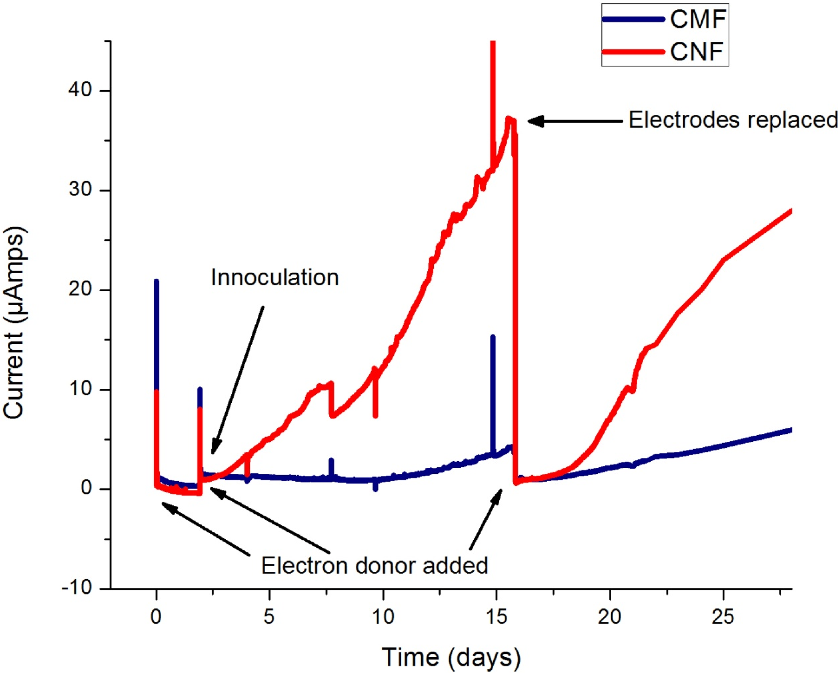
3.1. Current Production

The differences in current production between CNF and CMF working electrodes were monitored amperometrically (Figure 1). The CNF electrode generated several times more current than CMF throughout the experiment and is comparable to current generation from previous experiments [29]. The superior performance by CNF is confirmed by the fact that it exhibited a ~10-fold increase in current over that of CMF and that after the substitution of new electrodes into the MEC on day 15, current production by both CNF and CMF returned to the same levels exhibited prior to electrode replacement. Again, current production by CNF was substantially higher.
Figure 1. Amperometric data from a MEC inoculated with Shewanella oneidensis MR-1. Current production by carbon nanofiber mats/CNF (red) and carbon micfiber paper/CMF (blue) was monitored over a 4 week period.
Energies 08 01817 g001
The shapes of the I-t (current vs. time) curves throughout the experiment are identical and differ primarily in magnitude, with CNF producing current up to a factor of 10 more. The length of time given to the bacteria to colonize the electrode and generate current is well beyond times allotted in various experiments for biofilm formation suggesting that the time allowed for bacteria to agglomerate on the surface is not an issue [20,30]. However, determining whether the current was generated by a biofilm or a planktonic mass is important and can be elucidated using CV.

3.2. Cyclic Voltammograms

Cyclic voltammetry was performed on both electrodes on day 2 and on day 15. On day 2, the voltammograms for CMF and CNF are similar in amplitude and shape (Figure 2A). However, the voltammograms taken on day 15 (Figure 2B) show that CNF is trending more towards a Nernst-Monod sigmoidal curve [24,25] while CMF maintains a similar shape to that exhibited on day 2. After fitting the CV data taken on day 15 to the Nernst Monod Model (Figure 2B) it is easy to see that the CV for CNF correlates better to the Nernst-Monod sigmoidal shape than the CV for CMF.
Figure 2. Cyclic voltammograms for carbon nanofiber mats/CNF (red) and carbon microfiber paper/CMF (blue) at Day 2 (A); and Day 15 (B) of the experiment. Day 15 was chosen because of the difference in current production. Electrode replacement took place after the CV. CVs were scanned from −0.7 V to +0.3 V vs. Ag/AgCl at 2 mV/s.
Energies 08 01817 g002

3.2.1. Biofilm-Based Electron Transfer

CVs for an anode-respiring biofilm will exhibit different shapes than CVs for a planktonic biomass using mediators. Biofilms using conduction based electron transfer will have a voltammogram with a sigmoidal profile [24,25] while mediated electron transfer (planktonic biomass) will often show simple oxidation and reduction peaks [8].
The shapes of the voltammograms taken on day 15 (Figure 2B) show that CNF is trending toward a sigmoidal curve, like that of the Nernst-Monod model, while the shape of the voltammogram for CMF shows no significant changes from day 2. The fact that CNF correlates better with its Nernst-Monod model fit suggests that it formed a more complete conducting biofilm-electrode than CMF. Specifically, the sigmoidal profile generated by CNF on the forward scan and the decrease of the reduction peak on the reverse scan support this trend in the CNF voltammogram. The fact that most of the current for CNF is generated above the redox potential of riboflavin (−0.41 V vs. Ag/AgCl) also supports the idea that mediated transfer was not responsible for the increase in current production. This suggests that electricity from the CNF electrode is being produced by electron transfer from a biofilm. The SEM images in Figure 3 confirm that CNF has formed a substantial biofilm on its surface.

3.2.2. Comparison of Electroactive Surface Area and Kinetics Using CVs

There is no indication in the CVs (Figure 2) that CNF has a significant advantage because it has more electroactive surface area. If the increased current production by the CNF electrode were merely a function of surface area, the shape of the voltammogram for both electrodes would be identical differing only in the magnitude of current production. In other words, the shapes of the voltammograms would look the same, but the voltammogram for CNF would be tilted up vertically because of higher current production.
Since a kinetic advantage is often obtained from electron transfer for materials that are similar in size with its reductant (i.e., cytochromes or mediators) [31] it is important to account for the size disparity between the constituent materials for the electrodes (i.e., the size difference between carbon nanofibers and carbon microfibers). If the voltammogram for the CNF electrode is shifted horizontally to the left, relative to the voltammogram of the CMF electrode, this would indicate that CNF is more efficient than CMF at catalyzing the reaction. In the voltammograms of Figure 2A, the horizontal positions for the onset of current are identical; neither electrode displayed a kinetic advantage (i.e., no large decrease in the activation overpotential). In other words, the similarity between the voltammograms taken on day 2 (Figure 2A) suggests that neither electrode possessed improved catalytic properties. As a result, the advantage of using CNF is not due to higher specific surface areas (i.e., higher concentration of active sites) or faster kinetics. This may mean that other factors (i.e., electrode conductivity and electrode morphology) contributed to the increased current production and biofilm formation on CNF.

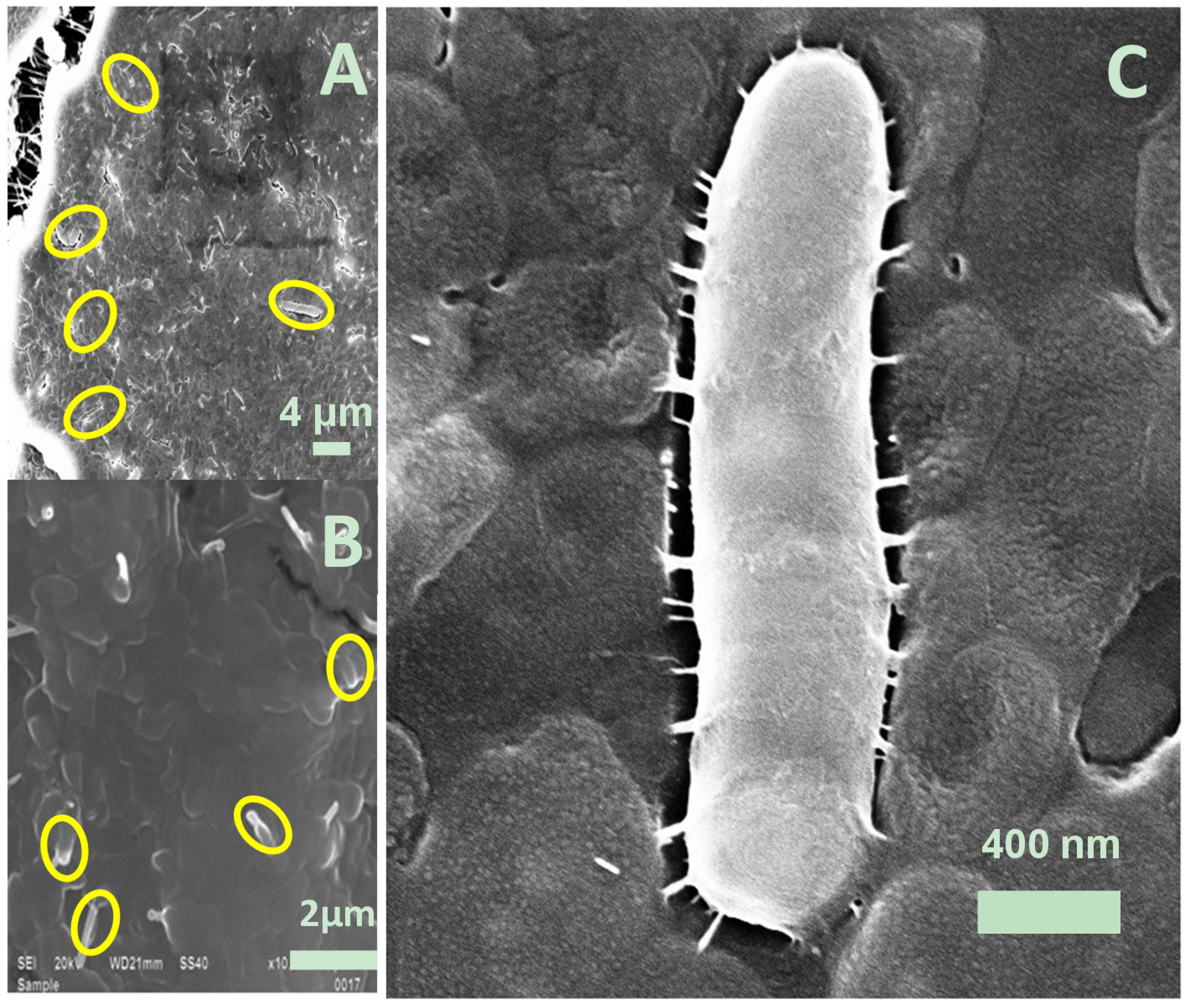
3.3. SEM Images for Biofilm Colonization

SEM images were used to demonstrate biofilm colonization on electrodes. Images in Figure 3 highlight the biofilm that formed on CNF mats while SEM imaging of the CMF mat showed no appreciable biofilm. Micrographs of the CNF electrode reveal a biofilm as well as outlines of cells (Figure 3A,B) and are similar to other micrographs of Shewanella oneidensis MR-1 biofilms on electrodes [30]. Figure 3C is a magnification of a single bacterium embedded in the CNF biofilm-electrode.
Figure 3. SEM images of increasing magnification of anodes evaluated in an MEC for 2 weeks and inoculated with Shewanella oneidensis MR-1. Images of carbon nanofiber mat/CNF images of increasing magnication (A,B); A magnified image of a single bacterium, set in a biofilm, found on the CNF electrode is also shown (C).
Energies 08 01817 g003

Biofilm Formation

The differences in biofilm formation by Shewanella oneidensis MR-1 are less surprising when we consider that it can also respire electrodes as a planktonic biomass and that single physical mutations to Shewanella oneidensis MR-1 have been shown to have profound effects on biofilm formation. For example, previous studies of biofilm formation by Shewanella oneidensis MR-1 showed that the presence of the flagellum, swimming motility, presence of a mannose-sensitive hemagglutinin type IV pilus, and pilus retraction played a significant role in the ability for Shewanella oneidensisMR-1 to form a biofilm. Specifically, the lack of a flagellum decreased the concentration of biomass (decreased biofilm formation), the lack of motility prevented the formation of a pronounced three dimensional biofilm architecture (bulk structure), the mutants defective in mannose-sensitive hemagglutinin type IV pilus biosynthesis had defects in initial attachment and the mutant defective in pilus retraction displayed poor propagation of the biofilm [30]. In addition, another study showed that mutants lacking the gene pilD (indicated in Type IV pilin production) and the protein secretion genes gsp and gspD produced less current in MFCs relative to the wild-type S. oneidensis MR-1. The images of the electrodes used in those microbial fuel cell experiments with the mutant lacking pilD revealed a lack of biofilm as compared to the wild-type [29]. These previous studies provide a foundation from which to investigate how morphology affects different phases of biofilm formation at a genetic level but, more importantly they highlight that small changes in how a cell interacts with its environment can have significant consequences for the entire biofilm. As the change in a substratum structure has affected biofilm formation in studies with mixed cultures [17,18,19,27] it is important to examine the differences in electrode morphology here for this pure culture.

3.4. Morphology of Sterile Electrodes

The electrode features revealed in the micrographs in Figure 4 highlight the morphological differences between CNF and CMF. The CNF mat shows a woven matrix of carbon nanofibers set upon a carbon scaffolding (Figure 4A) while CMF exhibits more of a rigid interlinked structure (Figure 4D). The typical diameter of the constituents used in CMF are ~10 μm while the carbon nanofibers are ~200 nm in diameter (Figure 4E vs. 4C). Carbon nanofibers are more flexible and carbon microfibers are linear and rigid. It is important to note the difference in morphology at the scale of a single bacterium when comparing electrodes in Figure 4 because the electrode features, relative to the size of the bacteria (i.e., 1–3 μm), are orders of magnitude different. CMF exhibits a constituent material with a serrated surface that is much larger (i.e., 10 μm) than a single bacterium. Conversely, CNF exhibits a constituent material much smaller (i.e., 200 nm) than a single bacterium. In addition to these characterizations, physical and electrical properties of both electrodes are listed in Table 1.
Figure 4. SEM images of increasing magnification (2000×, 5000×, and 10,000×) of pristine carbon nanofiber mats (AC); and carbon microfiber paper (DF).
Energies 08 01817 g004
Table 1. SEM images of increasing magnification (2000×, 5000×, and 10,000×) of pristine carbon nanofiber mats (AC); and carbon microfiber paper (DF).
SEM imagesCarbon microfiber paperCarbon nanofiber mats
Areal Wt (g/m2)16140
Thickness (cm)0.0380.015
Bulk resistivity (Ohm-cm)0.0060.075
Measured sheet resistivity (Ω/sq)0.175
Avg. diameter of constituent material10 μm0.2 μm
Bondingsp2sp2
Surface modificationsNoneNone

Impact of Electrode Morphology.

A single bacterium of Shewanella oneidensis MR-1 attaching to the surface of CNF would be in contact with multiple nanofibers (Figure 4A–C) but would cover only a portion of a single fiber of CMF (Figure 4B,D,F). Since the bacteria adhere to the features of the electrode it is important that the space between the features of each electrode be within a distance that bacteria can effectively collaborate. This distance, while not established quantitatively, has been shown to influence biofilm formation in medical studies [17]. That same influence is mimicked here as the tighter spacing/morphology of the CNF electrode spurs on better biofilm formation. While a minimum threshold for surface rigidity (stiffness) has been shown to inhibit biofilm accumulation [32] for other bacteria, the “softer” and more mesh-like CNF shows no such issues here as demonstrated by the prevalence of biomass on the electrode.

3.5. Differences in Electrode Conductivity

Electrode conductivity is a function of areal weight (mass/geometric surface area). A more densely packed material (i.e., higher areal weight) translates into a smaller resistance to current (i.e., high conductivity). CMF has a larger areal weight and a higher conductivity yet it is CNF that produces more biofilm and more current. It seems that the smaller conductivity of CNF does not affect the formation and performance of its biofilm-electrode.
A recent study by Malvankar et al. [33] showed, for Geobacter sulfurreducens, that there is a direct correlation between conductivity of the biofilm and current production. They observed biofilm conductivities as high as 0.5 S/m. In our studies, CNF showed a conductivity of 1300 S/m while CMF had a conductivity of ~15,500 S/m. The differences in these values support the idea that the conductivities for CNF and CMF have no significant effect on differences in current production because both conductivities were substantially greater than the highest reported biofilm conductivities and because the electrode that performed better, CNF, had the lower conductivity. Additionally, even with electrode materials with higher resistivities Chen et al. [27] was able to generate much higher current densities with mixed cultures suggesting that for general electrode materials there is not a strong correlation between resistivity/conductivity and current density.
Ultimately, the CNF electrode generated more current (Figure 1), exhibited a voltammogram that showed the current was being generated by a biofilm (Figure 2), and showed substantial coverage by bacteria when examined under a SEM after the experiment (Figure 3). The results presented here illustrate the overall trend and repeatability seen in multiple experiments. Here we used two sets of electrodes to demonstrate the consistency with which CNF outperforms CMF. Since the electrodes were exposed in the same reactor at the same time, differences in current production are best explained by differences in the nature of the electrode materials.
The advantage typically associated with CNF is the increased surface area [34], better kinetics [35], and high conductivity [36]. In this case however, the advantage of using CNF electrodes was its electrode surface morphology created by its thinner constituent carbon materials. This provided a better mesh for bacterial colonization and growth which produced a more substantial biofilm-anode and led to an increase in current production.

4. Conclusions

In this study, Shewanella oneidensis MR-1 produced significantly more current with CNF than CMF. The examination of sterile electrodes showed that CNF and CMF differed in morphology, surface area, size of the constituent material, and conductivity. After accounting for differences in surface area, size of the constituent material, and electrode conductivity the results suggests surprisingly that the morphology (i.e., tighter spacing/size of the features) of the electrode surface of CNF is what enables the formation of electricity producing biofilms by a pure culture relative to CMF. Therefore, controlling electrode morphology and structure may have significant consequences for biofilm-electrode formation and current production in other pure cultures.

Acknowledgments

This work was supported in part by the Mascaro Center for Sustainable Innovation. David V. P. Sanchez acknowledges the Alfred P. Sloan Foundation (NACME), National Science Foundation Graduate Research Fellowship, National Science Foundation IGERT traineeship, Jeff Gralnick, Pat Lake (Applied Sciences) and special thanks to Jeff Lawrence, Brian Goddard, and Kristen Butela, for assistance with microbiology techniques.

Conflicts of Interest

The authors declare no conflict of interest.

References

  1. Bond, D.R.; Lovley, D.R. Electricity production by Geobacter sulfurreducens attached to electrodes. Appl. Environ. Microbiol. 2003, 69, 1548–1555. [Google Scholar] [CrossRef] [PubMed]
  2. Franks, A.E.; Malvankar, N.; Nevin, K.P. Bacterial biofilms: The powerhouse of a microbial fuel cell. Biofuels 2010, 1, 589–604. [Google Scholar] [CrossRef]
  3. Torres, C.I.; Marcus, A.K.; Lee, H.-S.; Parameswaran, P.; Krajmalnik-Brown, R.; Rittmann, B.E. A kinetic perspective on extracellular electron transfer by anode-respiring bacteria. FEMS Microbiol. Rev. 2010, 34, 3–17. [Google Scholar] [CrossRef] [PubMed]
  4. Reguera, G.; Nevin, K.P.; Nicoll, J.S.; Covalla, S.F.; Woodard, T.L.; Lovley, D.R. Biofilm and nanowire production leads to increased current in Geobacter sulfurreducens fuel cells. Appl. Environ. Microbiol. 2006, 72, 7345–7348. [Google Scholar] [CrossRef] [PubMed]
  5. Chaudhuri, S.K.; Lovley, D.R. Electricity generation by direct oxidation of glucose in mediatorless microbial fuel cells. Nat. Biotechnol. 2003, 21, 1229–1232. [Google Scholar] [CrossRef] [PubMed]
  6. Tsai, H.-Y.; Wu, C.-C.; Lee, C.-Y.; Shih, E.P. Microbial fuel cell performance of multiwall carbon nanotubes on carbon cloth as electrodes. J. Power Sources 2009, 194, 199–205. [Google Scholar] [CrossRef]
  7. Liu, Y.; Harnisch, F.; Fricke, K.; Schröder, U.; Climent, V.; Feliu, J.M. The study of electrochemically active microbial biofilms on different carbon-based anode materials in microbial fuel cells. Biosens. Bioelectron. 2010, 25, 2167–2171. [Google Scholar] [CrossRef]
  8. Logan, B.E.; Hamelers, B.; Rozendal, R.; Schröder, U.; Keller, J.; Freguia, S.; Aelterman, P.; Verstraete, W.; Rabaey, K. Microbial fuel cells: Methodology and technology. Environ. Sci. Technol. 2006, 40, 5181–5192. [Google Scholar] [CrossRef] [PubMed]
  9. Pham, T.H.; Aelterman, P.; Verstraete, W. Bioanode performance in bioelectrochemical systems: Recent improvements and prospects. Trends Biotechnol. 2009, 27, 168–178. [Google Scholar] [CrossRef] [PubMed]
  10. Morozan, A.; Stamatin, I.; Stamatin, L.; Dumitru, A.; Scott, K. Carbon electrodes for microbial fuel cells. J. Optoelectron. Adv. Mater. 2007, 9, 221–224. [Google Scholar]
  11. Logan, B.; Cheng, S.; Watson, V.; Estadt, G. Graphite fiber brush anodes for increased power production in air-cathode microbial fuel cells. Environ. Sci. Technol. 2007, 41, 3341–3346. [Google Scholar] [CrossRef] [PubMed]
  12. Qiao, Y.; Li, C.M.; Bao, S.-J.; Bao, Q.-L. Carbon nanotube/polyaniline composite as anode material for microbial fuel cells. J. Power Sources 2007, 170, 79–84. [Google Scholar] [CrossRef]
  13. Rosenbaum, M.; Zhao, F.; Quaas, M.; Wulff, H.; Schröder, U.; Scholz, F. Evaluation of catalytic properties of tungsten carbide for the anode of microbial fuel cells. Appl. Catal. B Environ. 2007, 74, 261–269. [Google Scholar] [CrossRef]
  14. Sanchez, D.V.P.; Huynh, P.; Kozlov, M.E.; Baughman, R.H.; Vidic, R.D.; Yun, M. Carbon nanotube/platinum (Pt) sheet as an improved cathode for microbial fuel cells. Energy Fuels 2010, 24, 5897–5902. [Google Scholar] [CrossRef]
  15. Dewan, A.; Beyenal, H.; Lewandowski, Z. Scaling up microbial fuel cells. Environ. Sci. Technol. 2008, 42, 7643–7648. [Google Scholar] [CrossRef] [PubMed]
  16. Ebrahimi, S.; Fernández Morales, F.J.; Kleerebezem, R.; Heijnen, J.J.; van Loosdrecht, M.C.M. High-rate acidophilic ferrous iron oxidation in a biofilm airlift reactor and the role of the carrier material. Biotechnol. Bioeng. 2005, 90, 462–472. [Google Scholar] [CrossRef]
  17. Kappell, G.M.; Grover, J.P.; Chrzanowski, T.H. Micro-scale surface-patterning influences biofilm formation. Electron. J. Biotechnol. 2009, 12, 10–11. [Google Scholar] [CrossRef]
  18. Chen, S.; Hou, H.; Harnisch, F.; Patil, S.A.; Carmona-Martinez, A.A.; Agarwal, S.; Zhang, Y.; Sinha-Ray, S.; Yarin, A.L.; Greiner, A.; et al. Electrospun and solution blown three-dimensional carbon fiber nonwovens for application as electrodes in microbial fuel cells. Energy Environ. Sci. 2011, 4, 1417–1421. [Google Scholar] [CrossRef]
  19. He, G.; Gu, Y.; He, S.; Schröder, U.; Chen, S.; Hou, H. Effect of fiber diameter on the behavior of biofilm and anodic performance of fiber electrodes in microbial fuel cells. Bioresour. Technol. 2011, 102, 10763–10766. [Google Scholar] [CrossRef]
  20. Baron, D.; LaBelle, E.; Coursolle, D.; Gralnick, J.A.; Bond, D.R. Electrochemical measurement of electron transfer kinetics by Shewanella oneidensis MR-1. J. Biol. Chem. 2009, 284, 28865–28873. [Google Scholar] [CrossRef]
  21. Marsili, E.; Baron, D.B.; Shikhare, I.D.; Coursolle, D.; Gralnick, J.A.; Bond, D.R. Shewanella secretes flavins that mediate extracellular electron transfer. Proc. Natl. Acad. Sci. USA 2008, 105, 3968–3973. [Google Scholar] [CrossRef] [PubMed] [Green Version]
  22. Lanthier, M.; Gregory, K.B.; Lovley, D.R. Growth with high planktonic biomass in Shewanella oneidensis fuel cells. FEMS Microbiol. Lett. 2008, 278, 29–35. [Google Scholar] [CrossRef] [PubMed]
  23. Bard, A.J.; Faulkner, L.R. Electrochemical Methods: Fundamentals and Applications, 2nd ed.; John Wiley & Sons Inc.: New York, NY, USA, 2001. [Google Scholar]
  24. Torres, C.I.; Marcus, A.K.; Parameswaran, P.; Rittmann, B.E. Kinetic experiments for evaluating the nernst-monod model for anode-respiring bacteria (ARB) in a biofilm anode. Environ. Sci. Technol. 2008, 42, 6593–6597. [Google Scholar] [CrossRef] [PubMed]
  25. Marcus, A.K.; Torres, C.I.; Rittmann, B.E. Conduction-based modeling of the biofilm anode of a microbial fuel cell. Biotechnol. Bioeng. 2007, 98, 1171–1182. [Google Scholar] [CrossRef] [PubMed]
  26. Pavithra, D.; Mukesh, D. Biofilm formation, bacterial adhesion and host response on polymeric implants—Issues and prevention. Biomed. Mater. 2008, 3, 034003. [Google Scholar] [CrossRef] [PubMed]
  27. Chen, S.; He, G.; Carmona-Martinez, A.A.; Agarwal, S.; Greiner, A.; Hou, H.; Schröder, U. Electrospun carbon fiber mat with layered architecture for anode in microbial fuel cells. Electrochem. Commun. 2011, 13, 1026–1029. [Google Scholar] [CrossRef]
  28. Park, H.I.; Mushtaq, U.; Perello, D.; Lee, I.; Cho, S.K.; Star, A.; Yun, M. Effective and low-cost platinum electrodes for microbial fuel cells deposited by electron beam evaporation. Energy Fuels 2007, 21, 2984–2990. [Google Scholar] [CrossRef]
  29. Bretschger, O.; Obraztsova, A.; Sturm, C.A.; Chang, I.S.; Gorby, Y.A.; Reed, S.B.; Culley, D.E.; Reardon, C.L.; Barua, S.; Romine, M.F.; et al. Current production and metal oxide reduction by Shewanella oneidensis MR-1 wild type and mutants. Appl. Environ. Microbiol. 2007, 73, 7003–7012. [Google Scholar] [CrossRef] [PubMed]
  30. Thormann, K.M.; Saville, R.M.; Shukla, S.; Pelletier, D.A.; Spormann, A.M. Initial phases of biofilm formation in Shewanella oneidensis MR-1. J. Bacteriol. 2004, 186, 8096–8104. [Google Scholar] [CrossRef] [PubMed]
  31. Hirst, J. Elucidating the mechanisms of coupled electron transfer and catalytic reactions by protein film voltammetry. Biochim. Biophys. Acta Bioenerg. 2006, 1757, 225–239. [Google Scholar] [CrossRef]
  32. Epstein, A.K.; Hochbaum, A.I.; Kim, P.; Aizenberg, J. Control of bacterial biofilm growth on surfaces by nanostructural mechanics and geometry. Nanotechnology 2011, 22, 494007:1–494007:8. [Google Scholar] [CrossRef]
  33. Malvankar, N.S.; Tuominen, M.T.; Lovley, D.R. Biofilm conductivity is a decisive variable for high-current-density Geobacter sulfurreducens microbial fuel cells. Energy Environ. Sci. 2012, 5, 5790–5797. [Google Scholar] [CrossRef]
  34. McDonough, J.R.; Choi, J.W.; Yang, Y.; la Mantia, F.; Zhang, Y.G.; Cui, Y. Carbon nanofiber supercapacitors with large areal capacitances. Appl. Phys. Lett. 2009, 95, 243109:1–243109:3. [Google Scholar] [CrossRef]
  35. Wu, L.; Zhang, X.; Ju, H. Detection of NADH and ethanol based on catalytic activity of soluble carbon nanofiber with low overpotential. Anal. Chem. 2006, 79, 453–458. [Google Scholar] [CrossRef]
  36. Ra, E.J.; Raymundo-Piñero, E.; Lee, Y.H.; Béguin, F. High power supercapacitors using polyacrylonitrile-based carbon nanofiber paper. Carbon 2009, 47, 2984–2992. [Google Scholar] [CrossRef]

