
Optimal Energy Management Strategy of a Plug-in Hybrid Electric Vehicle Based on a Particle Swarm Optimization Algorithm


Abstract
:
1. Introduction
1.1. Review of the Literature
1.2. Motivation and Innovation
1.3. Outline of the Paper
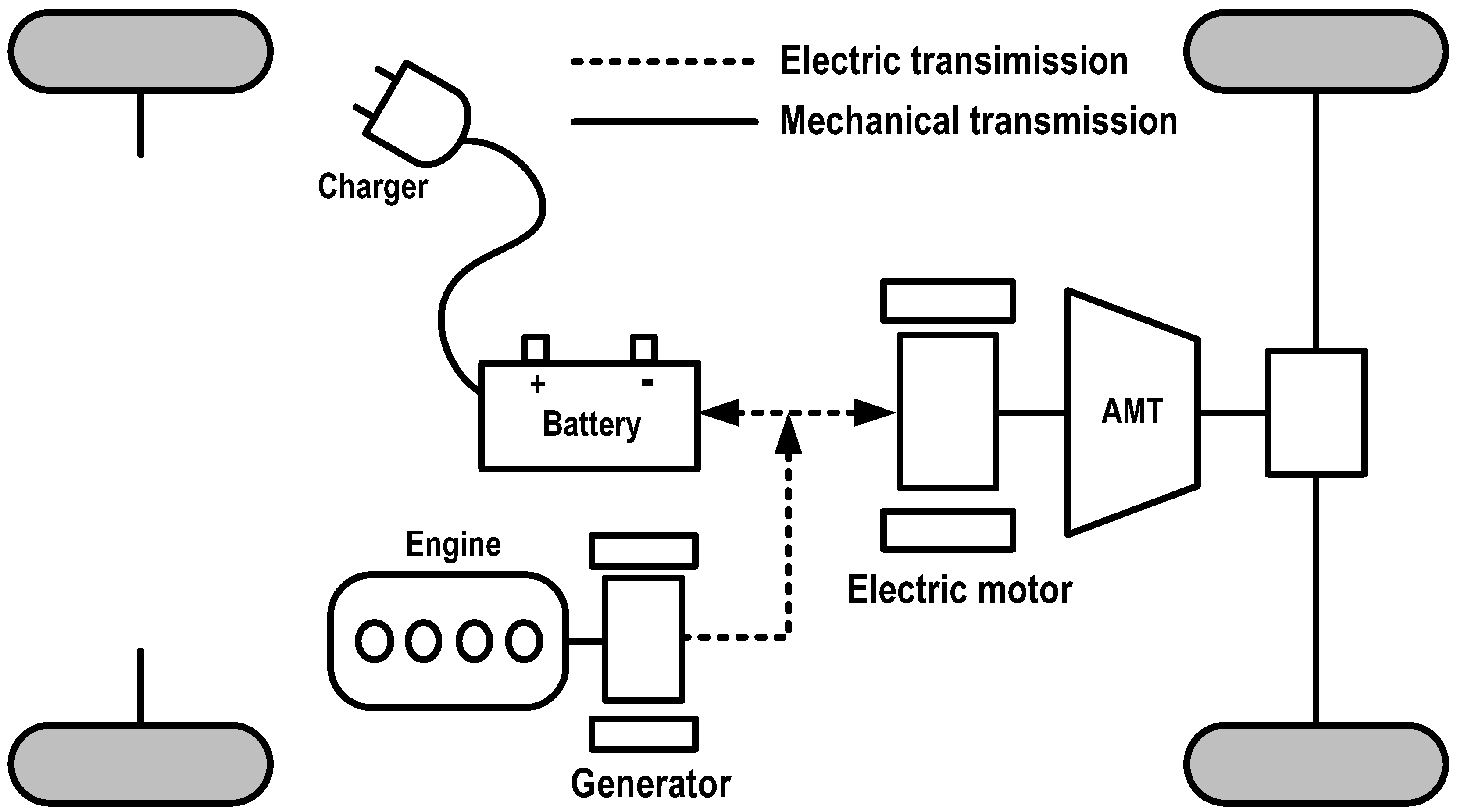
2. Powertrain System Model


3. Energy Management Approach Using a PSO Algorithm
3.1. Optimal Energy Control Problem

| Modes | Control rules |
|---|---|
| CD-E | if SoC > = 0.4 then EGS is OFF; Pbatt = Preq; end |
| CD-H | else if 0.2 <=SoC < 0.4 if Pe,max < Preq then Pe = P2; Pbatt = Preq− Pe; if PH < Preq ≤ Pe,max then Pe = P1; Pbatt = Preq − Pe; if PL* < Preq ≤ PH* then Pe = Preq; Pbatt = 0; if 0 < Preq ≤ PL then Pe = Popt; Pbatt = Pe − Preq; if Preq ≤ 0 then Pbatt = Preq; Pe = 0; end |
| CS | else Pe = max{0, Preq}, Pbatt = Preq − Pe; end |
3.2. Optimization Algorithm
| Step 1: Set the initial conditions. The particle swarm scale is set to M = 20 and maximum iteration times is set to N = 50. The bounds of each particle parameters are set according to Equations (11) and (12). Within the bounds, the positions of particles are given randomly and velocity is set 0. |
| Step 2: The first iteration time. Calculate the objective function (Equation (9)) for each particle according to rule-based strategy listed in Table 1 on the basis of the a priori driving cycle and then record each particle as their personal best the first time, denoted as P10…PM0, the best of which is chosen as the global best G0. |
| Step 3: Iteration. From the second iteration time on, the position of each particle X1k,…XMk and their velocity V1k…VMk is calculated as Equations (13) and (14). And at each iteration time, the objective functions are calculated and the personal best P1k…PMk and the global best Gk are recorded according to:
Pik={Xi*∣f(Xi*)=min[f(Xi0), f(Xi1),... f(Xik))]}
Gk={Pk,*∣f(Pk,*)=min[f(P1k), f(X2k),... f(XMk))]}
|
| Step 4: End optimization. When the iteration time reaches the maximum iteration time N, the PSO algorithm ends. The best particle is the optimized threshold values in rule-based strategy ρ* = GN. |

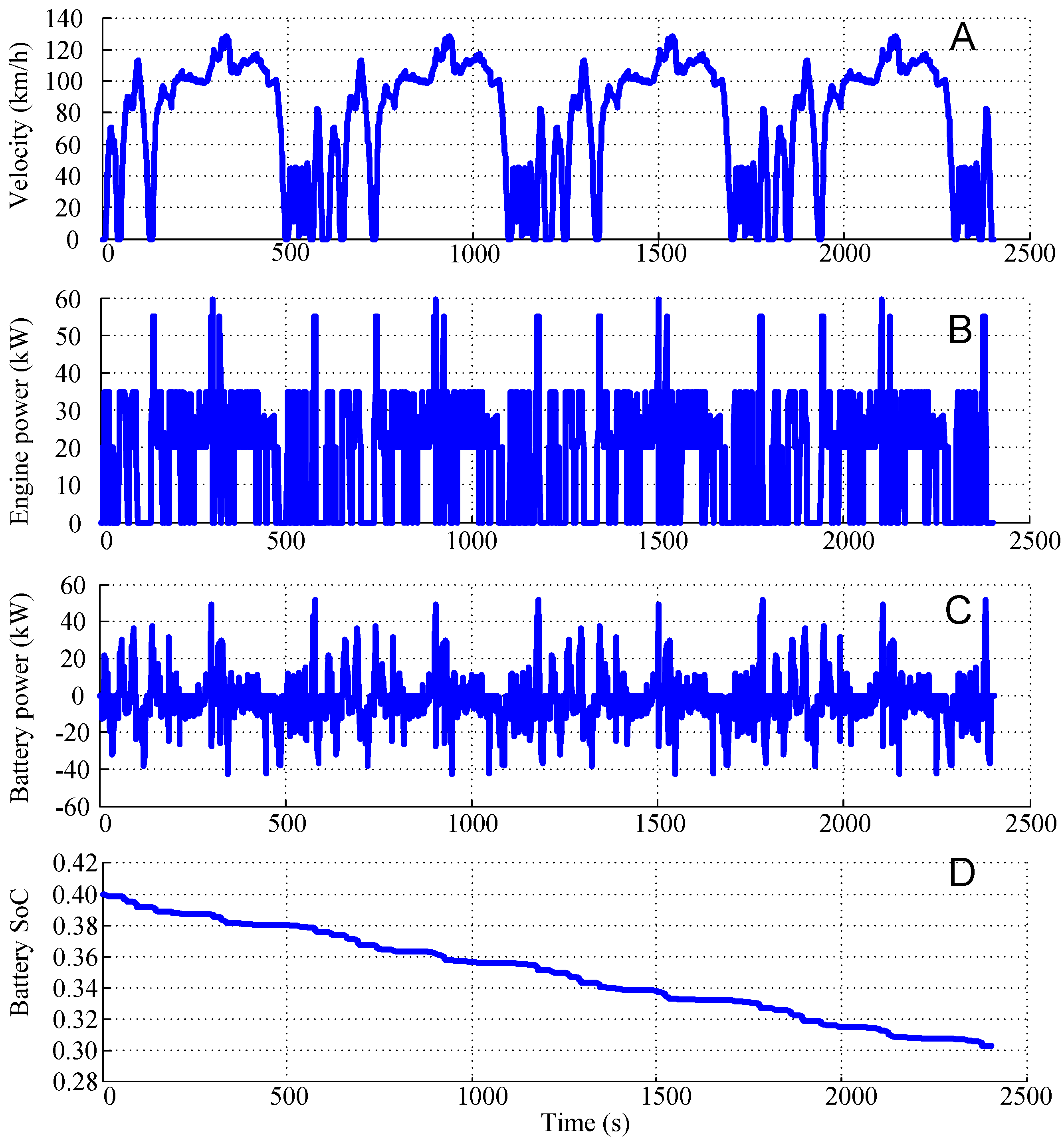
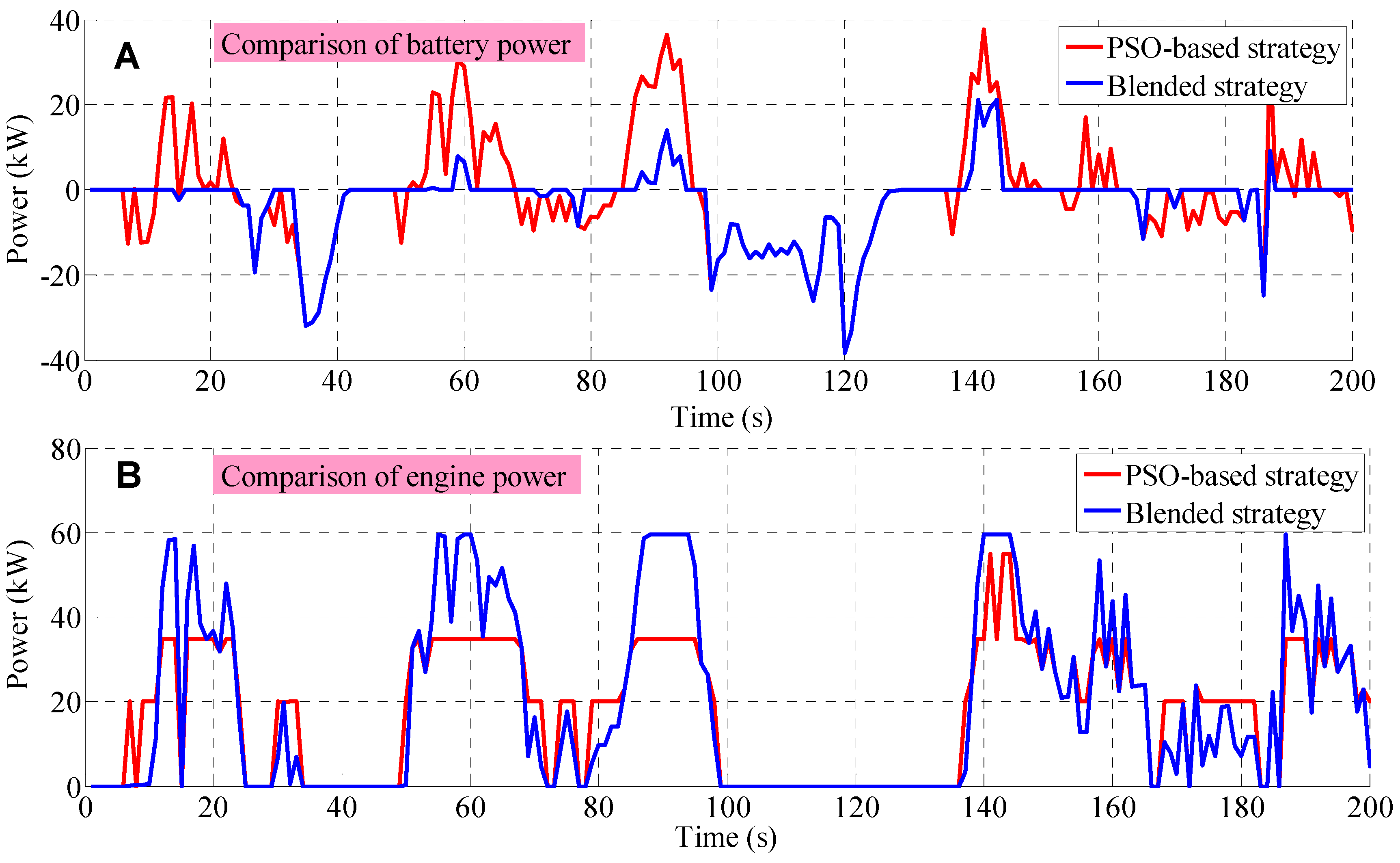
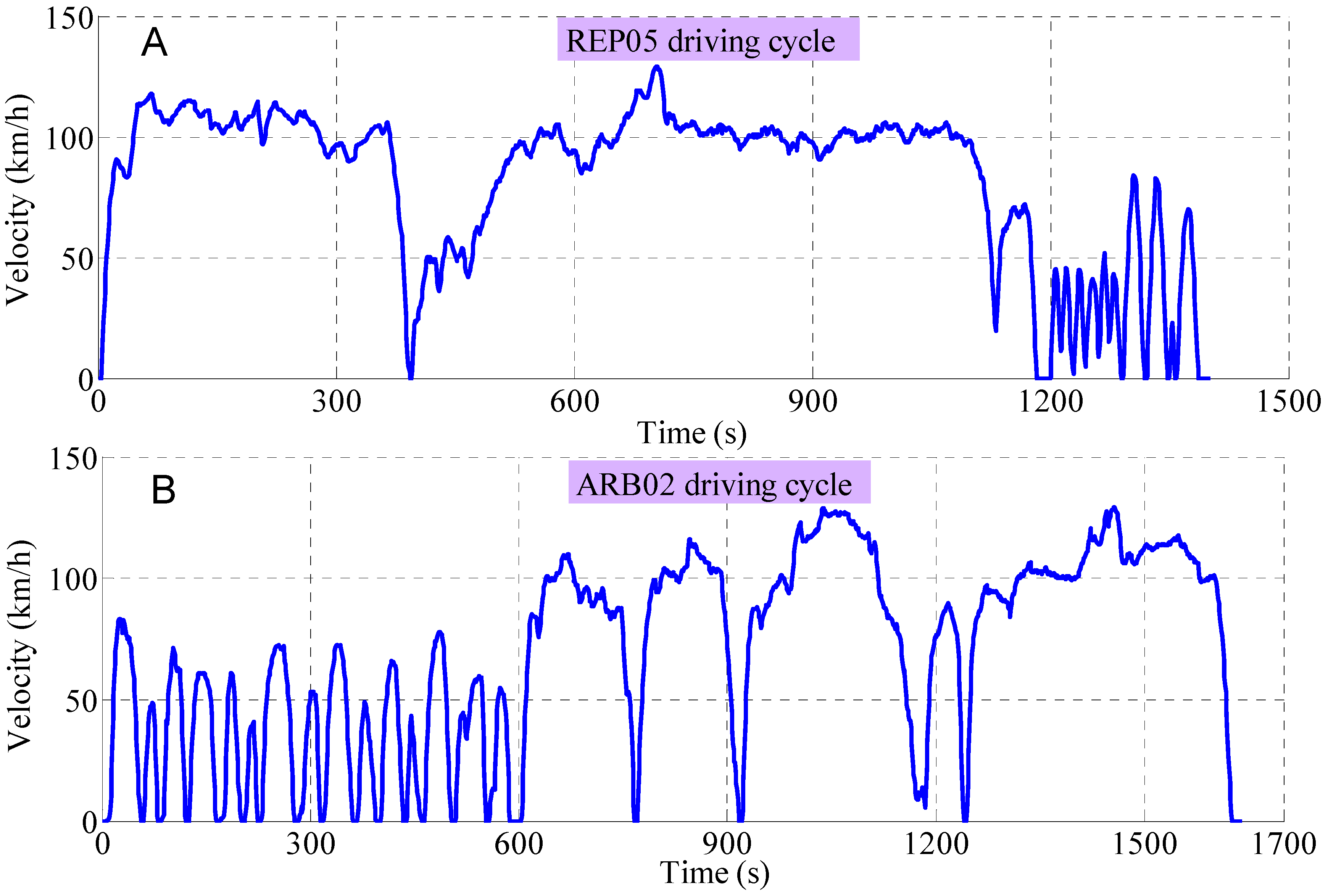
4. Simulation and Analysis
- if Pe,max < Preq then Pe = Pe,max; Pbatt = Preq − Pe;
- if 0 < Preq ≤ Pe,max then Pe = Preq; Pbatt = 0;
- if Preq ≤ 0 then Pe = 0; Pbatt = Preq.

| Methods | Cost function (L) | PSO vs. other methods |
|---|---|---|
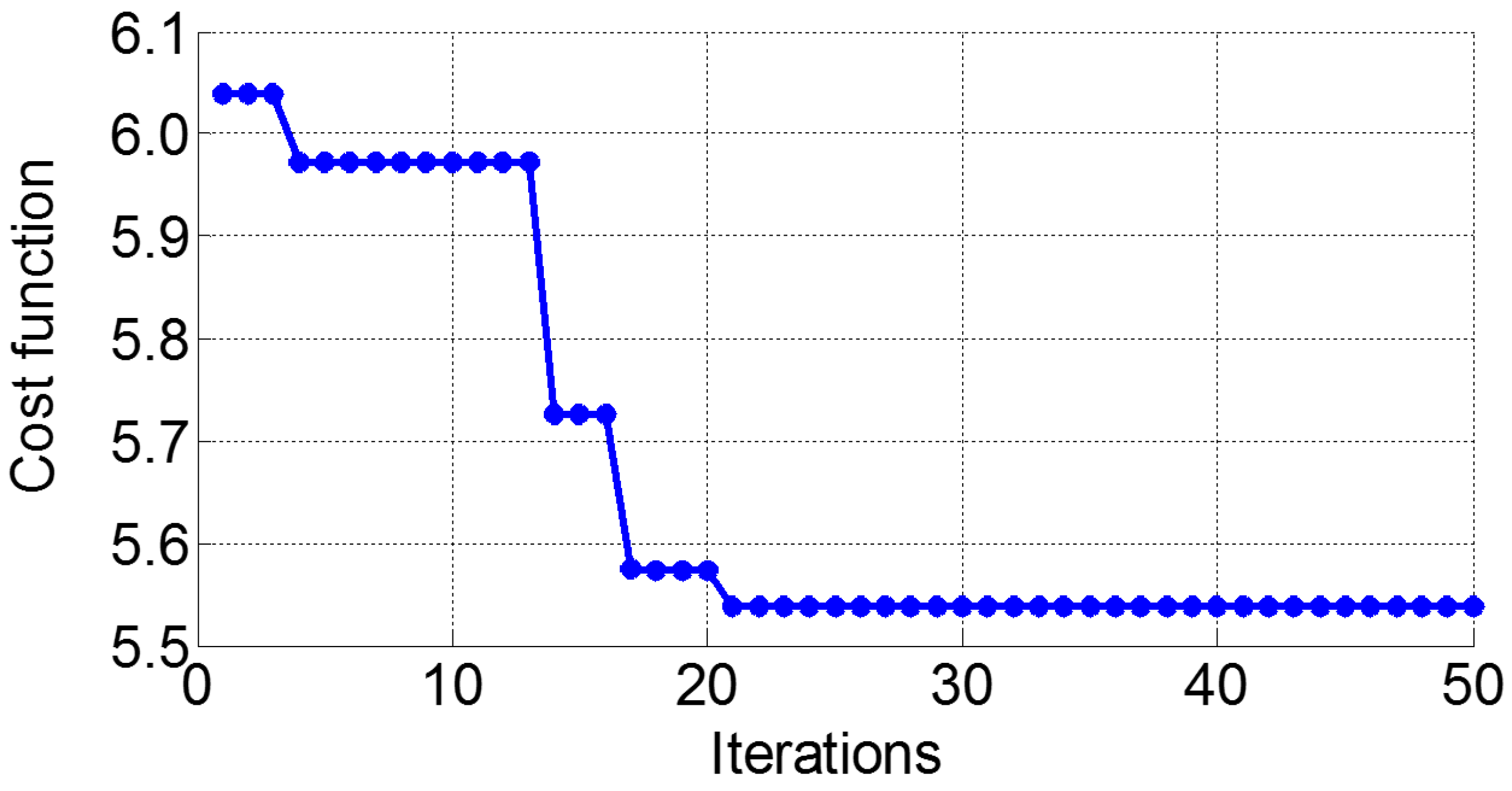
| PSO-based strategy | 5.54 | – |
| Original rule-based strategy (without optimization) | 6.04 | −8.28% |
| Blended strategy | 5.91 | −6.26% |


| Methods | Cost function (L) | PSO vs. other methods |
|---|---|---|
| PSO-based strategy | 5.42 | – |
| Original rule-based strategy (without optimization) | 5.52 | −1.81% |
| Blended strategy | 5.53 | −1.99% |
| Methods | Cost function (L) | PSO vs. other methods |
|---|---|---|
| PSO-based strategy | 5.94 | – |
| Original rule-based strategy (without optimization) | 6.06 | −1.98% |
| Blended strategy | 6.17 | −3.72% |
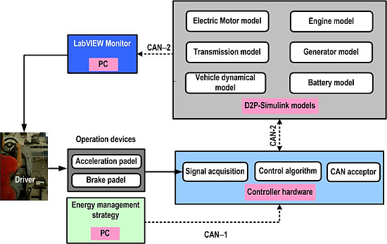
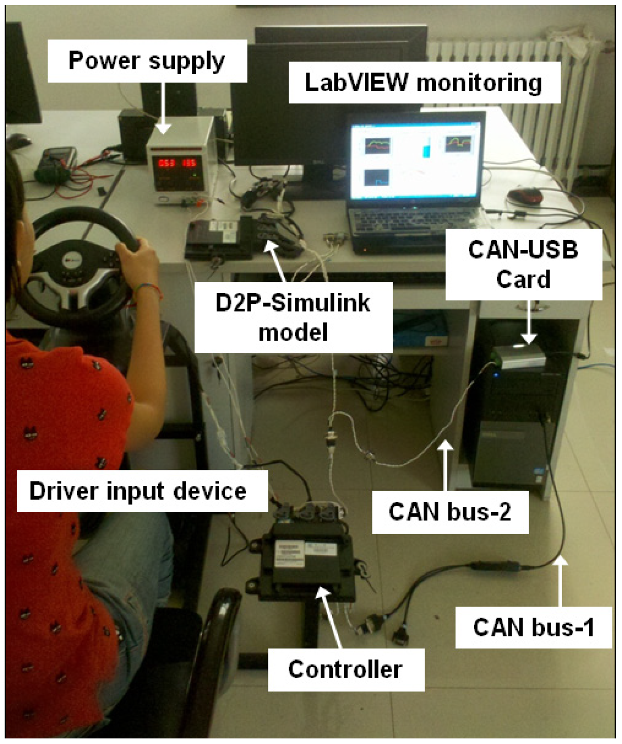
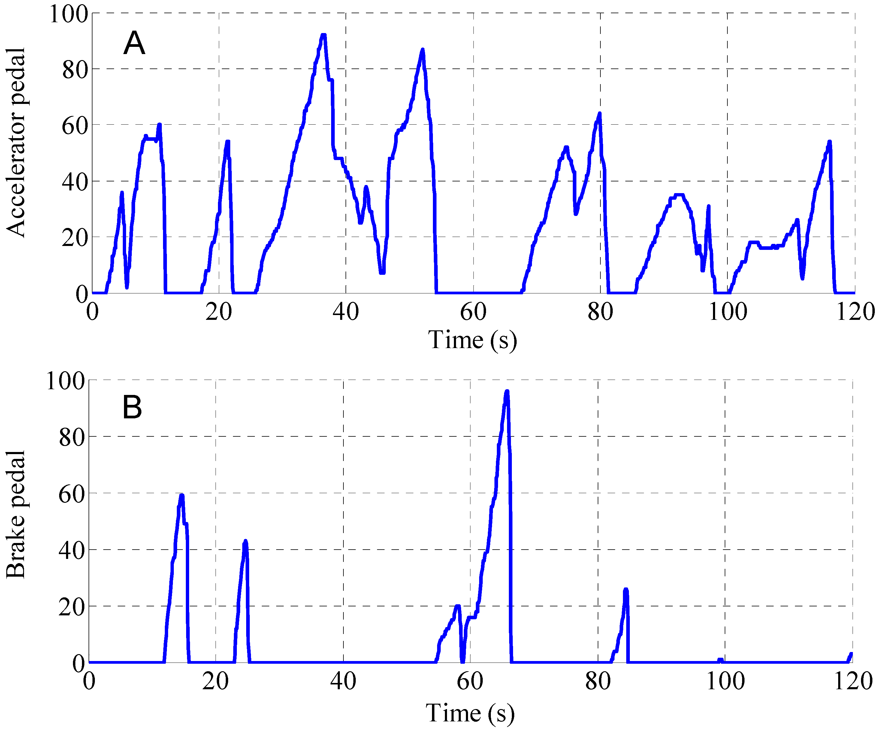
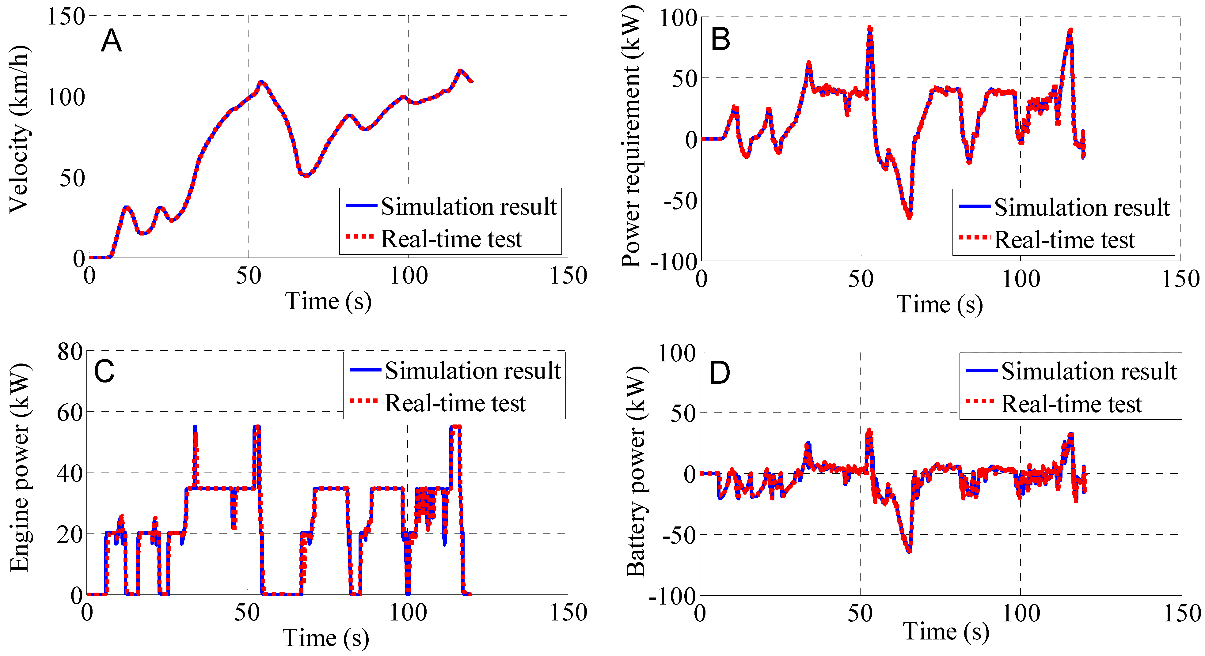
5. Driver-in-the-Loop Experiment


6. Conclusions
Nomenclature
| Pmot | electric motor power | u(t) | control policy |
| Pbatt | battery power | x(t) | state variable |
| Pe | engine-generator set power | ta | the time when it switched to the CD-H mode |
| Paug | auxiliary device power | tb | the time when it switched to the CS mode |
| ηm | electric motor efficiency | κ1, κ2 | price of oil fuel and electricity |
| ηbatt | battery efficiency | U | candidate solution space |
| ηegs | engine-generator set efficiency | c1, c2 | acceleration factors |
| λd* | driver operation signal | r1, r2 | random numbers, r1, r2∈(0,1) |
| ωm | rotation speed of the electric motor | w | inertia weight of the velocity |
| Pmot_max | maximum electric motor power | wmax, wmin | maximum and minimum limit of w |
| Pmot_min | minimum electric motor power | Preq | power requirement of the propulsion system |
| Ibatt | battery pack current | Pe,max | maximum EGS power |
| Voc | open circuit voltage | P1,P2 | threshold values in rule-based strategy |
| R0 | internal resistance of the battery | Popt | optimal efficient EGS power |
| K0~K4 | parameters in the battery model | instantaneous fuel consumption rate | |
| η | Coulombic efficiency | [p1(k), p2(k), p3(k), p4(k)]T | personal best position of the particle |
| Qnom | nominal capacity of the battery | [g1(k), g2(k), g3(k), g4(k)]T | global optimal position of the particle |
Acknowledgments
Author Contributions
Conflicts of Interest
References
- Chau, K.T.; Wong, Y.S. Overview of power management in hybrid electric vehicles. Energ. Convers. Manag. 2002, 43, 1953–1968. [Google Scholar] [CrossRef]
- Xiong, R.; Sun, F.C.; Gong, X.Z.; Cao, C.C. A data-driven based adaptive state of charge estimator of lithium-ion polymer battery used in electric vehicles. Appl. Energy 2014, 113, 1421–1433. [Google Scholar] [CrossRef]
- Doucette, R.T.; McCulloch, M.D. Modeling the prospects of plug-in hybrid electric vehicles to reduce CO2 emissions. Appl. Energy 2011, 88, 2315–2323. [Google Scholar] [CrossRef]
- Mapelli, F.L.; Tarsitano, D.; Mauri, M. Plug-in hybrid electric vehicle: Modeling, prototype realization, and inverter losses reduction analysis. IEEE Trans. Ind. Electron. 2010, 57, 598–607. [Google Scholar] [CrossRef]
- Liu, J.; Peng, H. Modeling and control of a power-split hybrid vehicle. IEEE Trans. Control Syst. Technol. 2008, 16, 1242–1251. [Google Scholar] [CrossRef]
- Gonder, J.; Markel, T. Energy management strategies for plug-in hybrid electric vehicles. In Proceedings of the SAE World Congress, Detroit, MI, USA, 16–10 April 2007; pp. 1–5.
- Zhang, X.; Mi, C.C.; Masrurb, A. Wavelet-transform-based power management of hybrid vehicles with multiple on-board energy sources including fuel cell, battery and ultracapacitor. J. Power Sources 2008, 185, 1533–1543. [Google Scholar] [CrossRef]
- Moura, S.J.; Callaway, D.S.; Fathy, H.K.; Stein, J.L. Tradeoffs between battery energy capacity and stochastic optimal power management in plug-in hybrid electric vehicles. J. Power Sources 2010, 195, 2979–2988. [Google Scholar] [CrossRef]
- He, H.W.; Xiong, R.; Zhao, K.; Liu, Z.T. Energy management strategy research on a hybrid power system by hardware-in-loop experiments. Appl. Energy 2013, 112, 1311–1317. [Google Scholar] [CrossRef]
- Serrao, L.; Onori, S.; Rizzoni, G. A comparative analysis of energy management strategies for hybrid electric vehicles. J. Dyn. Syst. Meas. Control 2011, 133, 1–9. [Google Scholar] [CrossRef]
- Xiong, R.; Sun, F.; He, H.; Nguyen, T. A data-driven adaptive state of charge and power capability joint estimator of lithium-ion polymer battery used in electric vehicles. Energy 2013, 63, 295–308. [Google Scholar] [CrossRef]
- Bayindir, K.Ç.; Gözüküçük, M.A.; Teke, A. A comprehensive overview of hybrid electric vehicle: Powertrain configurations, powertrain control techniques and electronic control units. Energ. Convers. Manag. 2011, 52, 1305–1313. [Google Scholar] [CrossRef]
- Sorrentino, M.; Rizzo, G.; Arsie, I. Analysis of a rule-based control strategy for on-board energy management of series hybrid vehicles. Control Eng. Pract. 2011, 19, 1433–1441. [Google Scholar] [CrossRef]
- Kim, J.; Kim, T.; Min, B.; Hwang, S.; Kim, H. Mode control strategy for a two-mode hybrid electric vehicle using electrically variable transmission (EVT) and fixed-gear mode. IEEE Trans. Veh. Technol. 2011, 60, 793–803. [Google Scholar] [CrossRef]
- Sun, F.; Xiong, R. A novel dual-scale cell state-of-charge estimation approach for series-connected battery pack used in electric vehicles. J. Power Sources 2015, 274, 582–594. [Google Scholar] [CrossRef]
- Martínez, J.S.; Hissel, D.; Péra, M.; Amiet, M. Practical control structure and energy management of a testbed hybrid electric vehicle. IEEE Trans. Veh. Technol. 2011, 60, 4139–4152. [Google Scholar] [CrossRef]
- Schoutena, N.J.; Salmanb, M.A.; Kheir, N.A. Energy management strategies for parallel hybrid vehicles using fuzzy logic. Control Eng. Pract. 2003, 11, 171–177. [Google Scholar] [CrossRef]
- Li, S.G.; Sharkh, S.M.; Walsh, F.C.; Zhang, C.N. Energy and battery management of a plug-in series hybrid electric vehicle using fuzzy logic. IEEE Trans. Veh. Technol. 2011, 60, 3571–3585. [Google Scholar] [CrossRef]
- Hu, X.; Murgovski, N.; Johannesson, L.; Egardt, B. Energy efficiency analysis of a series plug-in hybrid electric bus with different energy management strategies and battery sizes. Appl. Energy 2013, 111, 1001–1009. [Google Scholar] [CrossRef]
- Unger, J.; Kozek, M.; Jakubek, S. Nonlinear model predictive energy management controller with load and cycle prediction for non-road HEV. Control Eng. Pract. 2015, 36, 120–132. [Google Scholar] [CrossRef]
- Kermani, S.; Delprat, S.; Guerra, T.M.; Trigui, R.; Jeanneret, B. Predictive energy management for hybrid vehicle. Control Eng. Pract. 2012, 20, 408–420. [Google Scholar] [CrossRef]
- Zhang, C.; Vahidi, A. Route preview in energy management of plug-in hybrid vehicles. IEEE Trans. Contr. Syst. Technol. 2012, 20, 546–553. [Google Scholar] [CrossRef]
- Borhan, H.; Vahidi, A.; Phillips, A.M.; Kuang, M.L. MPC-based energy management of a power-split hybrid electric vehicle. IEEE Trans. Contr. Syst. Technol. 2012, 20, 593–603. [Google Scholar] [CrossRef]
- Kim, N.; Cha, S.W.; Peng, H. Optimal equivalent fuel consumption for hybrid electric vehicles. IEEE Trans. Contr. Syst. Technol. 2012, 20, 817–825. [Google Scholar] [CrossRef]
- Moura, S.J.; Fathy, H.K.; Callaway, D.S.; Stein, J.L. A stochastic optimal control approach for power management in plug-in hybrid electric vehicles. IEEE Trans. Contr. Syst. Technol. 2011, 19, 545–555. [Google Scholar] [CrossRef]
- Borhan, H.A.; Vahidi, A.; Phillips, A.M.; Kuang, M.L.; Kolmanovsky, I.V. Predictive energy management of a power-split hybrid electric vehicle. In Proceedings of the American Control Conference, St. Louis, MO, USA, 10–12 June 2009.
- Montazeri-Gh, M.; Poursamad, A.; Ghalichi, B. Application of genetic algorithm for optimization of control strategy in parallel hybrid electric vehicles. J. Franklin Inst. 2006, 343, 420–435. [Google Scholar] [CrossRef]
- Abido, M.A. Optimal power flow using particle swarm optimization. Int. J. Elec. Power 2002, 24, 563–571. [Google Scholar] [CrossRef]
- Zhang, W.; Liu, Y. Multi-objective reactive power and voltage control based on fuzzy optimization strategy and fuzzy adaptive particle swarm. Int. J. Electr. Power Energy Syst. 2008, 30, 525–532. [Google Scholar] [CrossRef]
- Xiong, R.; Sun, F.; Chen, Z.; He, H. A data-driven multi-scale extended Kalman filtering based parameter and state estimation approach of lithium-ion polymer battery in electric vehicles. Appl. Energy 2014, 113, 463–476. [Google Scholar] [CrossRef]
- Lin, C.C.; Peng, H.; Grizzle, J.W.; Kang, J.M. Power management strategy for a parallel hybrid electric truck. IEEE Trans. Contr. Syst. Technol. 2003, 11, 839–849. [Google Scholar] [CrossRef]
- Hu, X.; Murgovski, N.; Johannesson, L.M.; Egardt, B. Optimal dimensioning and power management of a fuel cell/battery hybrid bus via convex programming. IEEE/ASME Trans. Mechatron. 2014, 20, 457–468. [Google Scholar] [CrossRef]
- Ela, A.E.; Abido, M.A.; Spea, S.R. Optimal power flow using differential evolution algorithm. Electr. Power Syst. Res. 2010, 80, 878–885. [Google Scholar] [CrossRef]
- Wang, L.; Zhang, Y.; Yin, C.; Zhang, H.; Wang, C. Hardware-in-the-loop simulation for the design and verification of the control system of a series-parallel hybrid electric city-bus. Simul. Model. Pract. Theory 2012, 25, 148–162. [Google Scholar] [CrossRef]
- Kumari, M.S.; Maheswarapu, S. Enhanced genetic algorithm based computation technique for multi-objective optimal power flow solution. Int. J. Electr. Power Energy Syst. 2010, 32, 736–742. [Google Scholar] [CrossRef]
- Wu, X.; Cao, B.; Wen, J.; Bian, Y. Particle swarm optimization for plug-in hybrid electric vehicle control strategy parameter. In Proceedings of Vehicle Power and Propulsion Conference, Harbin, China, 3–5 September 2008.
- Hu, X.; Johannesson, L.; Murgovski, N.; Egardt, B. Longevity-conscious dimensioning and power management of the hybrid energy storage system in a fuel cell hybrid electric bus. Appl. Energy 2015, 137, 913–924. [Google Scholar] [CrossRef]
- Larsson, V.; Johannesson, L.; Egardt, B. Impact of trip length uncertainty on optimal discharging strategies for PHEVs. In Proceedings of the 6th IFAC Symposium Advances in Automotive Control, Munich, Germany, 12–14 July 2010; pp. 55–60.
- Fathy, H.; Kelly, J.; Bashash, S.; Keoleian, G.A. Plug-in hybrid electric vehicle charging policy optimization using particle swarms. In Proceedings of the 6th International Conference of the International Society for Industrial Ecology (ISIE), Berkeley, CA, USA, 7–10 June 2011.
© 2015 by the authors; licensee MDPI, Basel, Switzerland. This article is an open access article distributed under the terms and conditions of the Creative Commons Attribution license (http://creativecommons.org/licenses/by/4.0/).
Share and Cite
Chen, Z.; Xiong, R.; Wang, K.; Jiao, B. Optimal Energy Management Strategy of a Plug-in Hybrid Electric Vehicle Based on a Particle Swarm Optimization Algorithm. Energies 2015, 8, 3661-3678. https://doi.org/10.3390/en8053661
Chen Z, Xiong R, Wang K, Jiao B. Optimal Energy Management Strategy of a Plug-in Hybrid Electric Vehicle Based on a Particle Swarm Optimization Algorithm. Energies. 2015; 8(5):3661-3678. https://doi.org/10.3390/en8053661
Chicago/Turabian StyleChen, Zeyu, Rui Xiong, Kunyu Wang, and Bin Jiao. 2015. "Optimal Energy Management Strategy of a Plug-in Hybrid Electric Vehicle Based on a Particle Swarm Optimization Algorithm" Energies 8, no. 5: 3661-3678. https://doi.org/10.3390/en8053661