1. Introduction
In the context of the global demand for reduction in greenhouse gas emissions in the power sector as well as car industry and with the emergence of renewable energy sources, advanced battery systems are proposed for wide range of applications ranging from electrical vehicles (EVs) and hybrid electrical vehicles (HEVs) all the way up to smart grids. Currently, Li-ion batteries are one of the preferred choices in the field of battery research. They have several advantages over other chemistries such as NiMH and lead acid alternatives. These advantages include higher energy density, lower weight, and longer cycle life. An EV/HEV storage battery requires tens to hundreds of Li-ion single cells connected in series, parallel, or some combination thereof to attain the necessary voltage and power operation profiles [
1]. In order to provide a safe and reliable energy source in EVs/HEVs and for grid storage, it is necessary to have a battery management system (BMS) that provides an accurate onboard estimation of state of charge (SOC) for the Li-ion cells in the battery pack [
2]. This accuracy helps to increase the efficiency and longevity of electrical energy storage sources in EVs and HEVs [
3]. An appropriate battery model is necessary for proper design and operation of battery systems using BMS. Several modeling approaches are available: empirical models, statistical models and electrical models [
4,
5,
6]. Numerous models have been proposed in the literature that are accurate enough to show the electrical behavior of Li-ion batteries [
7,
8]. An electrical model is preferable for this study, since the applications covered in this paper are related to EVs/HEVs and smart grids [
7].
For batteries, the SOC is a quantity that represents the ratio of available battery capacity to its fully charged capacity [
9]. State of charge is an indication of how much longer the battery will be able to power the device it is connected to. Estimating the battery’s SOC is complicated by the fact that it is an internal state of the battery that is hard to measure [
10]. Moreover, SOC estimation has close correlation with estimation of the state of health (SOH) of a battery [
11]. As such, accurate estimation of SOC under all operating conditions still remains a challenge. In fact, this estimation becomes even more problematic as batteries age [
12]. Over the last few years, there have been significant efforts applied to improve the accuracy of SOC estimation of battery packs [
13] and different approaches have been used for this goal [
14].
The most basic approach to SOC estimation is the coulomb counting method [
15]. However, this method is prone to error since it is based on an open loop SOC estimator and a cumulative error-prone integral. This error increases with a lengthier operation time and when there are dramatic fluctuations in the current.
The Kalman filter (KF) is a well-known estimation theory introduced in 1960. The filter provides a recursive solution through a linear optimal filtering for estimating systems’ state variables. However, if the system is nonlinear, a linearization process is undertaken at each step which is used to approximate the nonlinear system with a linear time varying (LTV) system. Using the LTV system in KF, would lead to an extended Kalman filter (EKF) on a real nonlinear system. Basically, EKF works by making a prediction about a future value, obtaining a real measurement, comparing the two, moderating this difference, and adjusting its estimate with this moderated value [
16]. This means that the prediction relies on the present state as well as an estimate of controllable factors that affect the situation. After initialization, the Kalman filter repeatedly performs two steps. First, it predicts the value of the next state, system output, and error covariance. Next, using a measurement of system output, it corrects the present state estimate [
17]. When the model is nonlinear, the Kalman filter may be extended through a linearization procedure. This algorithm is referred as the EKF. The basic idea of the extended Kalman filter is to linearize the state-space model at each time instance around the most recent state estimate, depending on the particular function considered. Once a linear model is obtained, standard Kalman filter equations are applied. Since the battery model is a nonlinear system, the EKF method is used to deal with battery SOC estimation. In the EKF method for a battery, the input signal is the charging/discharging current. The EKF compares the measured terminal voltage of batteries with its estimated value to correct the estimation parameters for SOC. Process noise and measurement noise of the filter for the battery system are considered uncorrelated zero-mean white Gaussian stochastic processes. This filter is explained in detail in [
18]. The application of these filters on batteries have been studied extensively [
14,
19,
20,
21].
Moreover, researchers have found that integration of several individual approaches may lead to a more accurate SOC estimation. In [
22], SOC estimation was followed by an open circuit voltage estimation using an EKF method. In addition to that, adaptive Kalman filtering combined with a coulomb counting method was used for SOC estimation of an EV battery pack in [
23]. Among those methods, some are used in EV’s/HEV’s BMSs successfully, which are also based on EKF [
17]. However, there are issues regarding the accuracy of SOC estimation as a battery pack ages, which is discussed here.
The aging phenomenon is caused by two main mechanisms: loss (fracture) of active materials and Solid-Electrolyte Interface (SEI)-layer growth [
24]. These factors account for capacity fading and an increase in impedance [
25]. These effects cause changes in the battery model parameters used in SOC estimation methods. Moreover, it is important to recognize that SOC is a short-term characteristic, whereas capacity fading is a long-term phenomenon. However, there is a close correlation between the two. In order to correlate SOC with capacity fading and altered model parameters, it is necessary to have a method that provides an accurate SOC estimation. To provide an accurate SOC estimation, this model adaptively changes parameters during the aging process.
In the previous work [
12], a new method for updating the electrical model of an aged cell was introduced and later an EKF methodology was applied for SOC estimation. The parameters of an electrical model of aged cells were obtained by applying a brute-force optimization algorithm in combination with an EKF method that resulted in a relatively minor error of 4%. The electrical model is presented in
Figure 1. Sensitivity analysis was done on the capacitor and resistor values of model parameters to gain an understanding of changes in their values and effect on circuit behavior [
18].
In [
26], a new method based on improved adaptive EKF methods was introduced to deal with the higher power characteristic of EV Li-ion cells. This model, however, was unable to estimate SOC at initial steps. Moreover, this algorithm assumes that initial SOC starts from zero, which leads to some errors in EKF estimation in later steps. Therefore, if the battery’s BMS relies solely on this method, there will be errors in initial SOC estimations. For example, this problem can be serious if the battery system is connected to the grid and an accurate estimate of SOC cannot be determined.
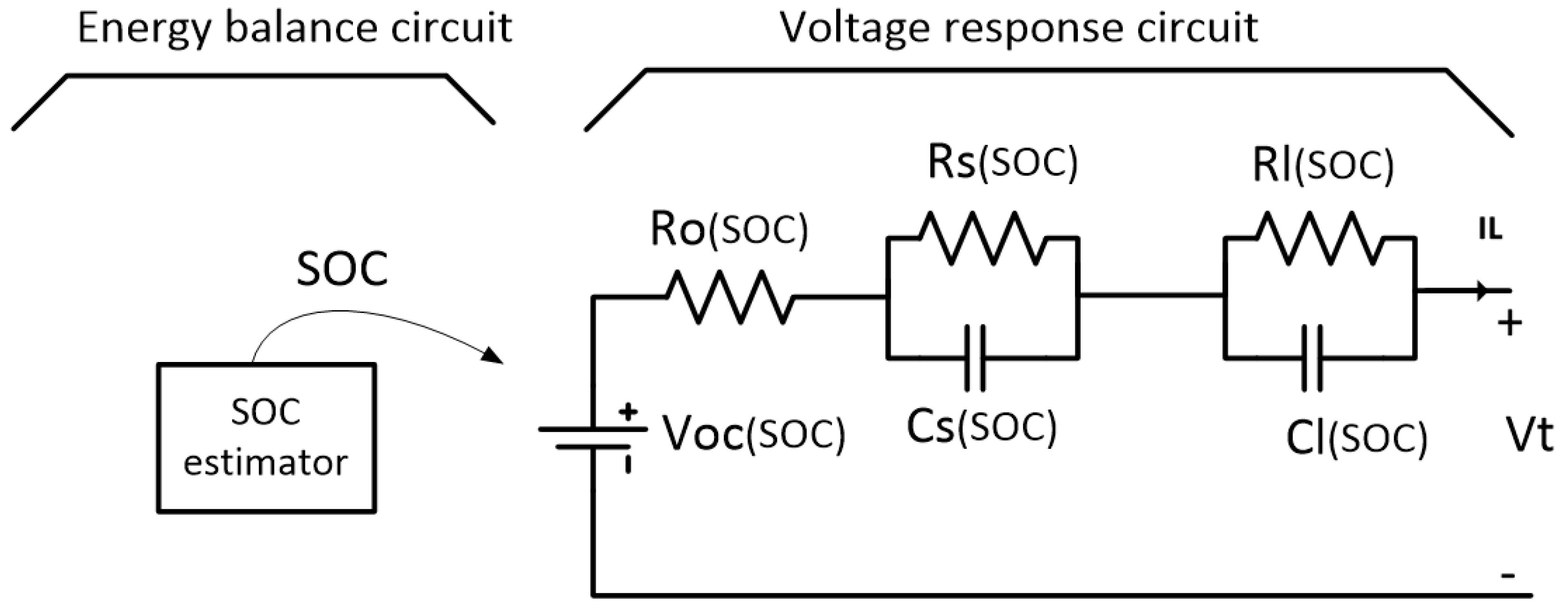
Figure 1.
Schematic diagram of the hybrid electrical model.
Figure 1.
Schematic diagram of the hybrid electrical model.
Although several SOC estimation algorithms based on fuzzy estimation have been used to estimate SOC and SOH [
27,
28], errors caused by aging have been ignored. As such, this paper proposes a new SOC estimation method denoted as a fuzzy-IEKF for SOC estimation that can be applied to both new and aged cells. The proposed approach introduces a fuzzy method with a new class of membership function that estimates initial SOCs. This function takes the last value saved in the BMS for a battery pack’s SOC as an initial value for use in a coulomb counting method used jointly with IEKF. Subsequently, the IEKF method is applied for SOC estimation in which a single unit model is considered for the battery pack. To verify the proposed method, a LiFePO
4 aged battery pack consisting of 120 cells connected in series with a nominal voltage of 432 V was used for the SOC estimation process.
2. Battery Electrical Modeling
SOC is one of the most important measurements for BMSs. It reflects an internal state of each cell and cannot be measured directly during battery operation [
29]. However, SOC can be estimated using a model of a battery. Different battery models have been developed to capture Li-ion battery performance for various purposes. Among the models, the equivalent circuit and electrochemical models are used widely in EV studies. Electrical models use equivalent electrical circuits to show I-V characteristics of batteries by using current and voltage sources, resistors and capacitors. Due to the remarkable relaxation effect of a Li-ion battery and model requirements, a model similar to the model presented in [
7] is selected as the battery model and is shown in
Figure 1.
This model is sufficiently accurate and covers different empirical conditions such as the working conditions of EVs/HEVs. The energy balance side of the model is the part of it that delivers SOC to the voltage response side of the model. In this model, the ohmic resistance R
o consists of the bulk resistance and surface layer impedance, accounting for the electric conductivity of the electrolyte, separator and electrodes. The activation polarization is modeled by R
s and C
s and the concentration polarization is modeled by R
l and C
l. Some papers model the polarization effect by one RC branch, but results presented in [
26,
30] show that modeling with two RC branches is more accurate and SOC estimation derived in this way has less error. To cover practical conditions and considering suitable complexity of the model for fast calculations in the BMS, its components are assumed to be a function of SOC. The practical conditions include different charging/discharging current profiles and environment temperature. However, since the optimization algorithm has some errors in estimation of model parameters, the discharging equations presented in [
7] are neglected. It is assumed that there is just one operating function for charging and discharging and tests are performed at constant temperature. The electrical behavior of a practical model shown in
Figure 1 can be expressed as follows:
where
Vt,
Voc and
IL are the battery terminal voltage, battery open circuit voltage and load current respectively.
Vs and
Vl are the short and long time transient voltage responses at RC branches.
The equations for the electrical elements of the voltage response circuit of the model presented in
Figure 1, including impedance elements are modeled as follows [
25]:
where
a1–
a6,
b1–
b5,
c1–
c3,
d1–
d5,
g1–
g4 and
h1–
h6 are identified values based on experiments with the methods proposed in [
31].
Table 1 presents the identified impedance parameters for a new LiFePO
4 cell with a nominal capacity of 1.1 Ah.
Table 1.
Impedance parameters for a new cell.
Table 1.
Impedance parameters for a new cell.
| Parameters | Values | Parameters | Values | Parameters | Values | Parameters | Values |
|---|
| a1 | −6.001×10⁻¹ | b3 | 2.258×10⁻¹ | d2 | −1.011×10³ | h1 | 2.099×10⁶ |
| a2 | 22.1 | b4 | −7.210×10⁻² | d3 | 1.407×10³ | h2 | −5.980×10⁶ |
| a3 | 3.416 | b5 | 8.978×10⁻² | d4 | 3.885E2 | h3 | 5.991×10⁶ |
| a4 | 1.106×10⁻¹ | c1 | 1.079×10⁻² | g1 | 2.936E−1 | h4 | −2.948×10⁶ |
| a5 | −1.614×10⁻¹ | c2 | −10.99 | g2 | −19.93 | h5 | 5.983 |
| b1 | 1.300×10⁻¹ | c3 | 1.831×10⁻² | g3 | 4.724×10⁻² | h6 | −3.102×10⁴ |
| b2 | −2.899×10⁻¹ | d1 | 1.682×10² | g4 | −2.421×10⁻² | h7 | 2.232×10³ |
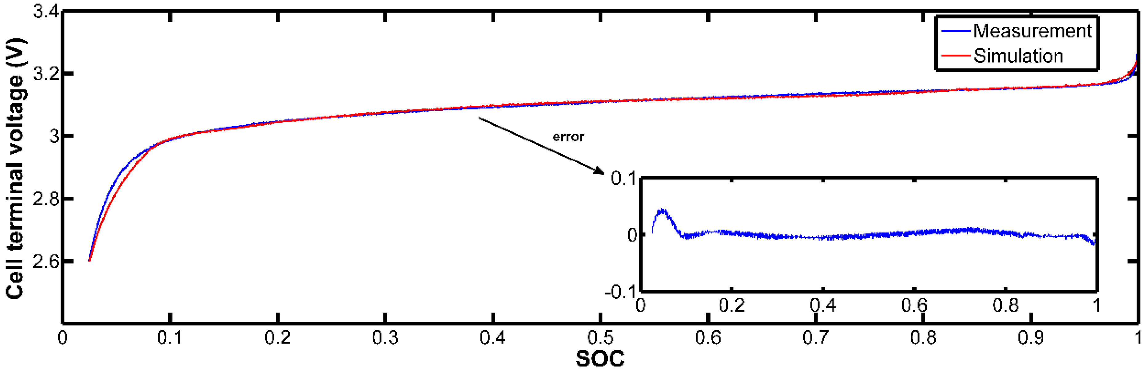
Figure 2 compares the measured voltage of the same cell with the model’s output voltage to show its accuracy. The discharging starts from a full charged condition with discharging current equal to 1C. The model was found to accurately simulate the voltage behavior of the cell. The voltage estimation error in the intervals of 10% and 90% of the SOC were less than 2 mv. This accuracy can be increased by modeling the electrical components with higher order polynomials. One more option for increasing the accuracy is to use more parallel RCs in the model. However, it would complicate the model and increase its estimation time. As such, we wouldn’t be able to estimate the SOC and the voltage in real time.
Figure 2.
Measured voltage and simulated voltage for a fully charged new cell.
Figure 2.
Measured voltage and simulated voltage for a fully charged new cell.
3. Model Adaptive-IEKF Method for the State of Charge (SOC) Estimation
The model adaptive-IEKF method is a novel method introduced in [
26] for SOC estimation of Li-ion cells in a battery pack. This method consists of two separate parts, a model adaptive part for updating the cell’s model and an IEKF side to estimate SOC. As a battery ages, the estimated SOC by EKF becomes less accurate [
12]. For precise SOC estimation of an aged cell, EKF requires an updated electrical battery model as presented in
Figure 1. Generally this second-order RC model is widely used to describe the dynamic and static characteristics of the battery. Sensitivity analysis performed in [
18] on this second-order RC model shows that highest sensitivity are on
Ro,
Rs and
Rl. In other words, these parameters need to be updated on battery model as a Li-ion cell ages. The updating method used in the electrical model has already been discussed in detail in [
26] and is presented in 5 steps in this paper. This process can be run by the BMS for a branch of a battery pack while other branches are working normally. However, since constant load on board is rare in practice and to avoid problems such as inconsistency between the branches and considering constant current-constant voltage method for charging, the first step of the procedure mentioned in [
26] is modified. Based on the presented method, the model update algorithm can be summarized by the following steps:
- 1)
Measure the terminal voltage while charging the cell with a constant current.
- 2)
Calculate the derivative of the measured voltage in step one.
- 3)
Assign two values of 92% and 15% to SOC as two reference points for a voltage derivative.
- 4)
Run the optimization algorithm to obtain updated model parameters.
- 5)
Insert the updated model into the IEKF method.
The updating process and IEKF method used in this work are shown in
Figure 3 and are described in details in [
26]. The impedance parameters in
Table 1 are updated based on the aging phenomenon and are listed in
Table 2. The SOC estimation error obtained by the IEKF method for a battery pack is depicted in
Figure 4. The reference SOC is based on the coulomb counting method. The battery pack used in this simulation consisted of 120 cells connected in series.
Figure 3.
The MAEKF algorithm in a block diagram.
Figure 3.
The MAEKF algorithm in a block diagram.
Table 2.
Differing impedance parameters for an aged cell as it ages.
Table 2.
Differing impedance parameters for an aged cell as it ages.
| b5 | 1.375E-1 | c3 | 1.845E-2 | g3 | 4.769E-2 |
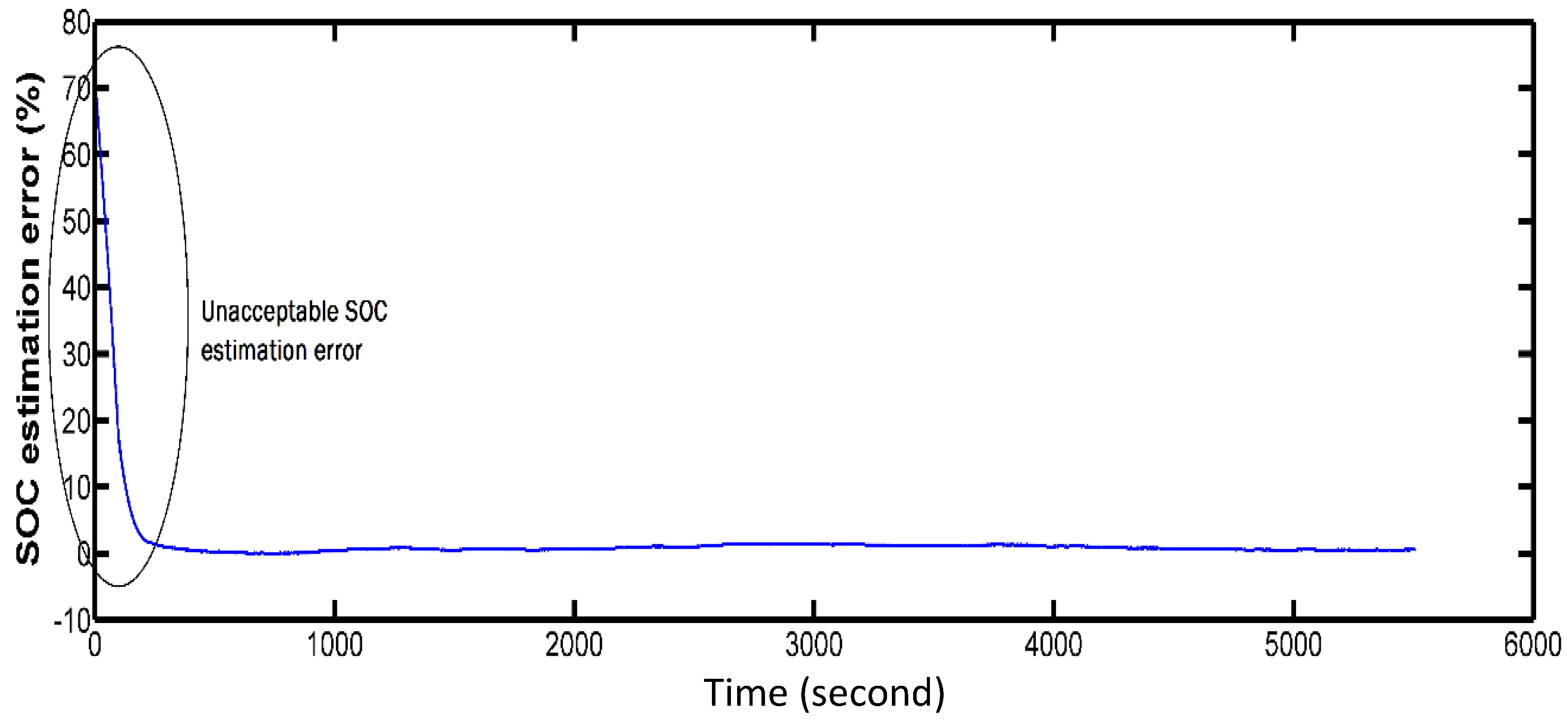
Figure 4.
SOC estimation error for a battery pack by improved extended Kalman filter (without using fuzzy estimation for initial minutes).
Figure 4.
SOC estimation error for a battery pack by improved extended Kalman filter (without using fuzzy estimation for initial minutes).
The single cell unit model used for this pack was presented in [
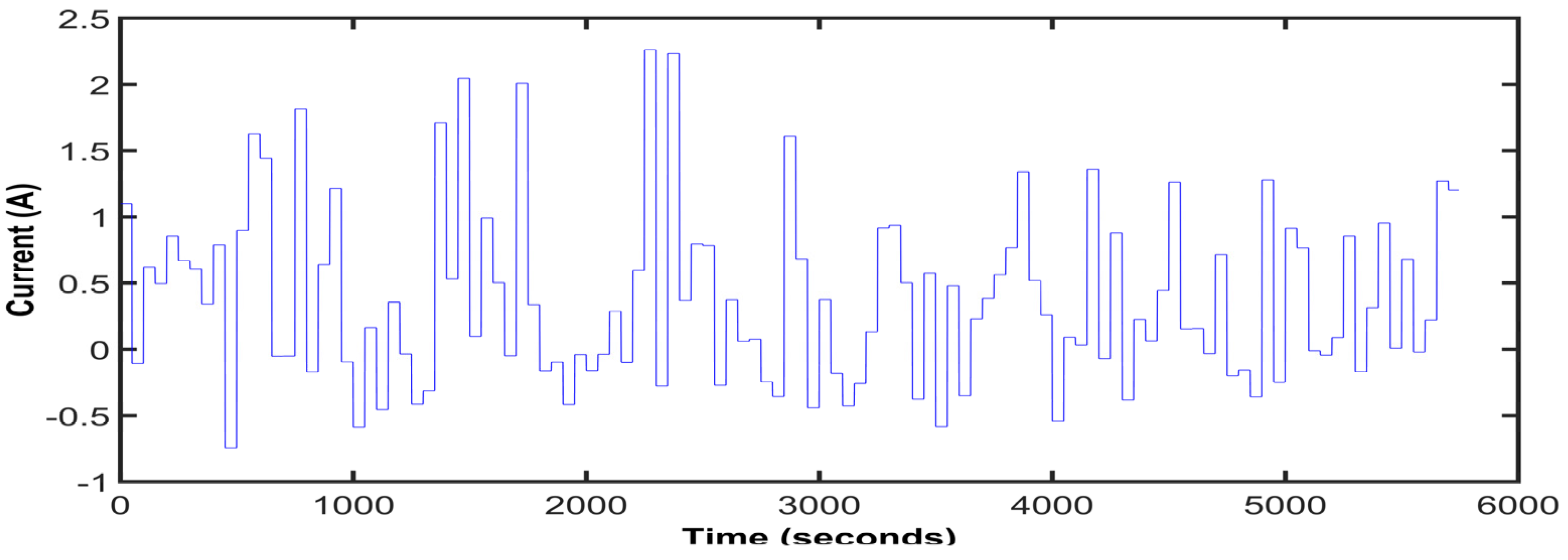
26]. A single cell unit model enables us to track SOC for the pack in real time, thanks to the very low computational burden of IEKF for SOC estimation. The charge/discharge current profile of the pack is shown in
Figure 5. In the current profile, the maximum value for charging a current is about 2.3A and the minimum value for discharging current is 0.7A. This test was performed at room temperature. Initial SOC for the pack was 66% and estimation for SOC started from 1%. As we can see from the SOC error graph depicted in
Figure 4, the estimation error is large and not useful for BMS calculations in the initial moments of the test. In the first four minutes of this test, the SOC estimation mean error was about 20%. To overcome this drawback and obtain an accurate SOC estimation for the whole duration of the charging/discharging process, a new fuzzy operator under a Dombi class [
32] was introduced. This operator combines IEKF’s estimation method with a coulomb counting approach. This fuzzy operator is discussed in detail in the following section.
Figure 5.
Current profile used for charging/discharging the battery pack on test for previous figure.
Figure 5.
Current profile used for charging/discharging the battery pack on test for previous figure.
4. Fuzzy Operator for the State of Charge (SOC) Estimation
In mathematics, a fuzzy set includes elements having degrees of membership. Fuzzy set theory permits the gradual assessment of the membership of the elements in a set; which is described with the aid of membership functions valued in an interval [0–1].
For two fuzzy sets “A” and “B” these membership functions are presented by µ
A (x) and µ
B (x), respectively [
33]. Fuzzy set operations are generalizations of crisp set operations. These operations are divided in two main categories: standard fuzzy set operations and aggregation operations. Fuzzy components, fuzzy intersections and fuzzy unions are standard operations and the rest are aggregation operations. An aggregation operation on fuzzy sets is an operation by which several fuzzy sets are combined in a desirable way to produce a single fuzzy set [
33].
An aggregation operation on n fuzzy set (2 ≤ n) is defined by function h:
There are three axioms for aggregation operations in fuzzy sets:
- 1)
- 2)
Monotonicity:
For any pair, <a1, a2, …, an> and <b1, b2, …, bn> of n-tuples such that ai, bi ϵ [0,1] for all i ϵ Nn, if for all i ϵ Nn, then h(a1, a2, …, an ) ≤ h(b1, b2, …, bn); that is, h is monotonic increasing in all its arguments.
- 3)
Continuity:
h is a continuous function.
Here we introduce an aggregation operation that can be used for SOC estimation during initial steps. Since this operator has some similarity with Dombi s-norm, we call it a Dombi aggregation operator:
where
a and
b are membership functions. λ
1 and λ
2 are constant values chosen from [0, ∞). Assuming λ
1 = 10 and λ
2 = 5 in this work, the operator will be:
The following proves that the operator satisfies the properties given in Equations (11)–(13).
We chose λ
1 = 10 and λ
2 = 5 and assume two pairs <
a1,
a2> and <
b1,
b2> where the first pair is smaller than the second pair and
ai,
bi ϵ [0,1] for
i = 1,2. Since pair (
a1,
a2) belongs to interval [0,1], 1/
ai is a number in the interval [1, ∞) and (1/
ai −1) is a number in the interval [1, ∞). In other words, as
ai increases, the denominator of the fraction at the above equation decreases. As a result, h(
a1,
a2) is less than h(
b1,
b2), which satisfies a monotonicity condition.
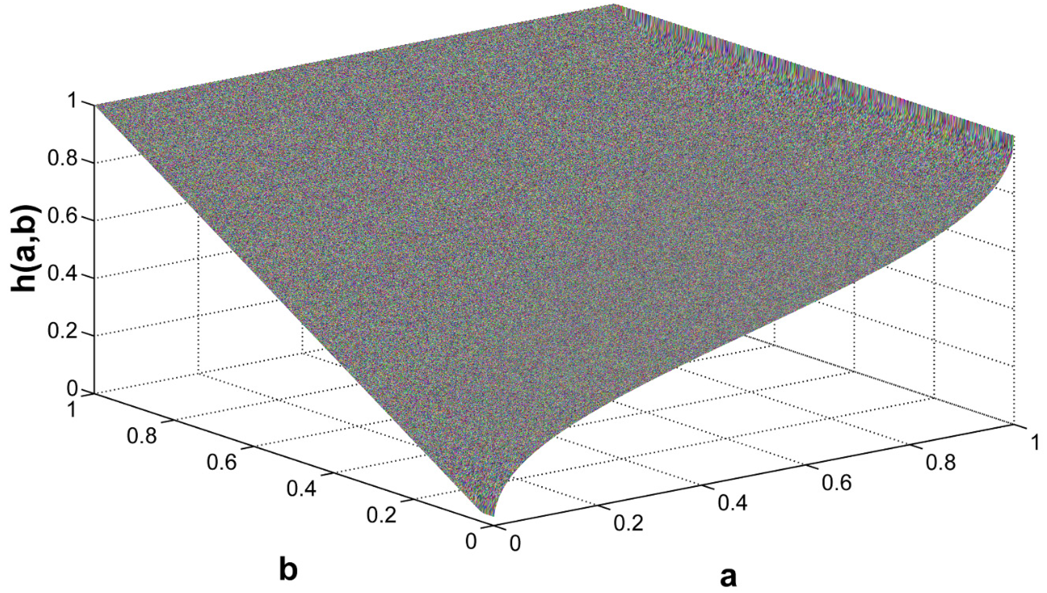
In order to justify the continuity property of the presented fuzzy operator, a fuzzy operator was plotted for
a ϵ [0,1] and
b ϵ [0,1] in
Figure 6.
Figure 6.
Graph of operator (15) for a ϵ [0,1] and b ϵ [0,1].
Figure 6.
Graph of operator (15) for a ϵ [0,1] and b ϵ [0,1].
In the proposed method, member function “a” is replaced by SOCcc which is a calculation of SOC by a coulomb counting method. λ1 and λ2 values are 10 and 5, respectively. To assure covering different working conditions (including different charging/discharging current profiles and initial SOCs), brute-force optimization approach is used for selecting lambda values. For this goal, in a SOC estimation test, possible combinations of λ
1 and λ
2 are tested. λ
1 = 10 and λ
2 = 5 had the least error. In this equation, SOC(0) is the latest SOC of the battery pack of the BESS saved in BMS. I(t) presents the charging/discharging current. Membership function “b” replaced by IEKF estimation. Equation (17) is the final SOC estimator formula for 500 initial steps:
For the first 500 initial steps, the SOC value is calculated from the first sentence in Equation (18), which is an output of the proposed fuzzy operator. The IEKF estimations reaches real SOC with almost 400 steps. However to be conservative, time step 500 is chosen as the switching time step for the main SOC estimator. The second sentence is valid for the rest of estimation steps. Equation (18) presents SOC estimators for the battery pack form the beginning of charging/discharging of the battery pack until SOC packs reach 10%:
If the SOC value cannot be retrieved from the BMS, an IKEF methodology is deployed to calculate its estimated value using the following equation:
Assuming that our batteries have similar capacities and have the same level of SOH, the following equation is used to define reference SOC for the battery pack [
34]:
where
ns is the number of cells in series and
SOCi denotes SOC for the
ith cell.
Cusable,i represents usable capacity, which indicates available capacity of the battery. This capacity decreases as the battery ages [
25] and is a criterion for batteries SOH. In [
35], authors discussed a method for updating this capacity based on the coulomb counting method. The same method is employed to calculate usable capacity of each battery in the first step of our proposed algorithm, as discussed in
Section 3. This procedure is explained further in the next paragraph.
Based on [
35], the usable capacity of each single battery is calculated by:
where “
I” denotes discharging current, and t
0 represents the time interval for calculating Δ
SOC. The exact value of Δ
SOC is needed in Equation (21) to calculate
Cusable. To overcome this difficulty, an estimated SOC derived by EKF is used while discharging the battery in the first step of proposed method in
Section 3. In that case, estimated
Cusable is equal to:
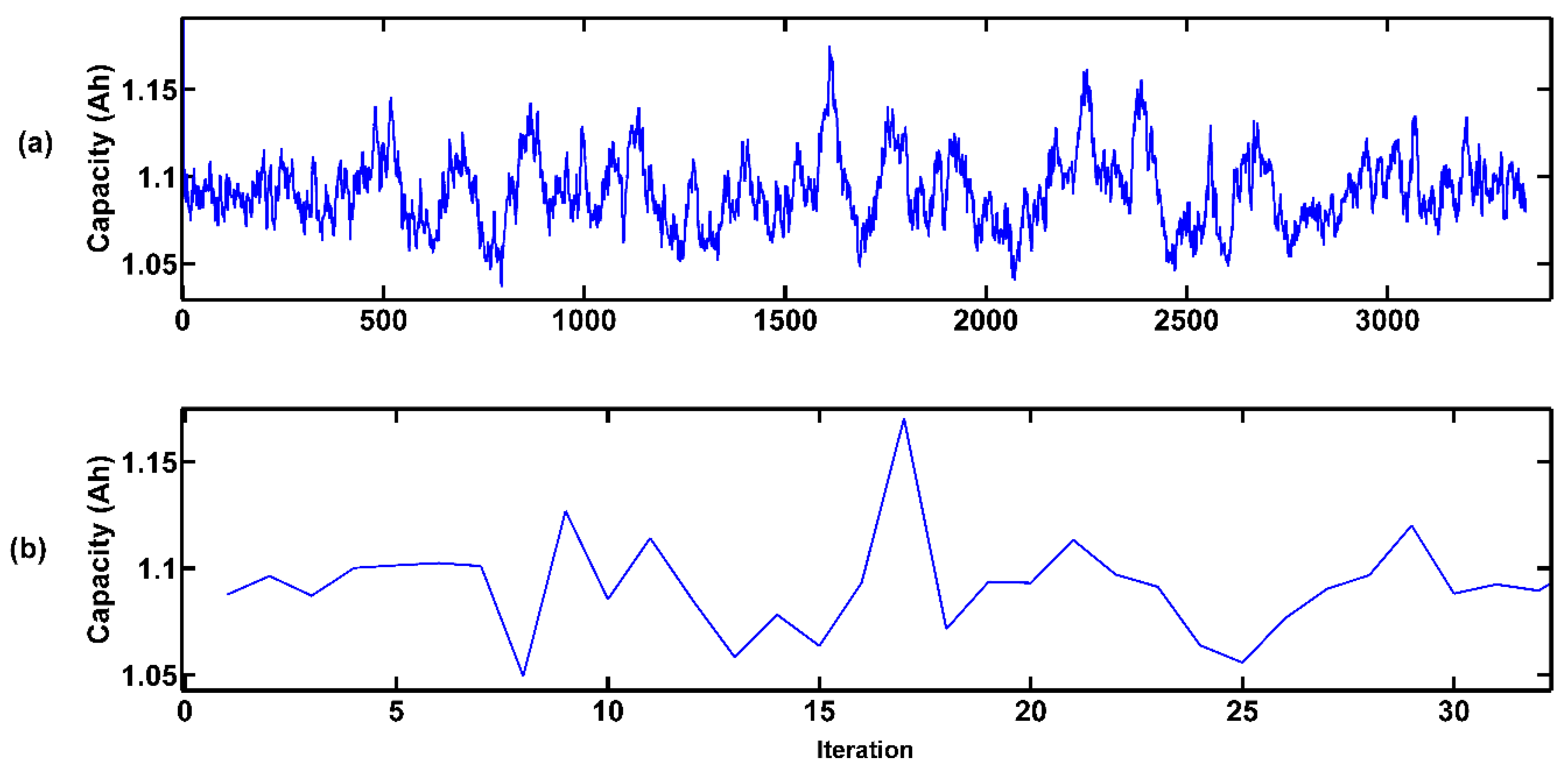
In our experiments, t
0 was set to 100, defining the window size for Equation (22) to 100 steps and the window is moved at each time step. The discharging time for a full single battery with 1.101 Ah capacity is about 3605 s. However, due to the nature of EKF, the estimated capacity at each time step has steep fluctuations as shown in
Figure 7a. To tackle this problem, the estimated capacities are filtered using a derivative of calculated capacities and by removing capacities lying outside [0.75–1.25] of the derivative interval. Estimated capacities before and after filtering are presented in
Figure 7. In this figure, the
X-axis is the iteration of running the C
usable estimation. The final estimated capacity for each of the batteries used in Equation (20) is the average of filtered results. As an example, the estimated capacity for a brand new single battery with 1.101 Ah capacity was about 1.091 Ah. This estimation for the same cell after an aging-cycling with 1.05 Ah capacity was 1.054 Ah. The aging history for this cell includes 220 cycles from fully charged to 10% SOC with 1C discharging current. The constant current, constant voltage (CCCV) method is used to charge the cell after 2 hour resting time between each cycling period.
Figure 7.
Estimated capacities with EKF (a) before filtering; (b) after filtering results. X-axis is iteration.
Figure 7.
Estimated capacities with EKF (a) before filtering; (b) after filtering results. X-axis is iteration.
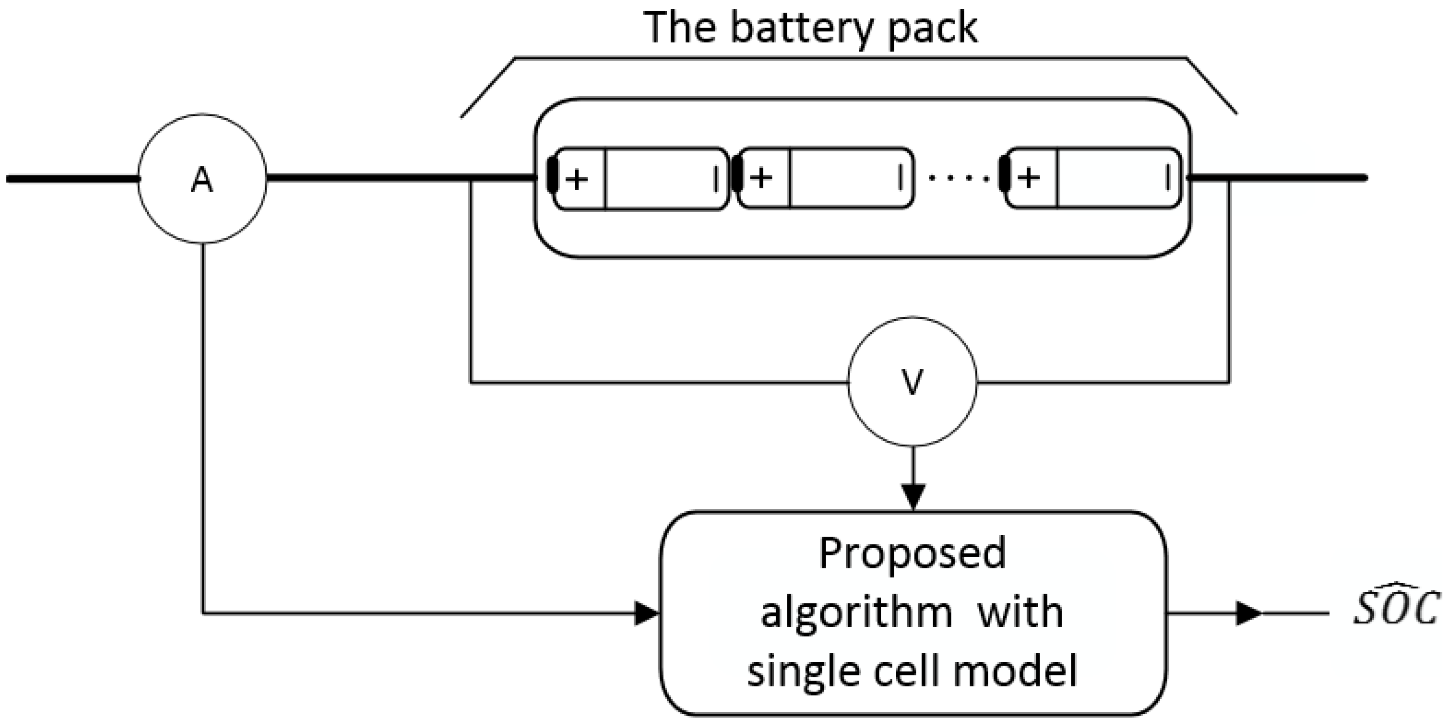
5. Experimental Results
The proposed method was tested at room temperature on a battery pack consisting of 120 LiFePO
4 cells connected in series. These cells were APR18650m1 LiFePO
4 batteries (A123 Systems, LLC), with similar SOH and 1.1 Ah nominal capacity, which were subjected to cycling under similar conditions for aging proposes as explained in last paragraph of the
Section 4. The ambient temperature and the initial temperature of cells were assumed to be 25 °C. For each cell of the pack after aging, a new electrical model was found after applying the proposed optimization algorithm on the aged battery pack. Construction of the whole platform for this test is presented in
Figure 8. In this platform, a pack’s voltage and charging/discharging current fed to the proposed algorithm, which has single cell model to estimate pack SOC. Moreover, for each test, all cells of the pack have almost close SOCs, which can be done by cell balancing techniques by the BMS.
Figure 8.
Construction of the whole platform for tests in
Section 5.
Figure 8.
Construction of the whole platform for tests in
Section 5.
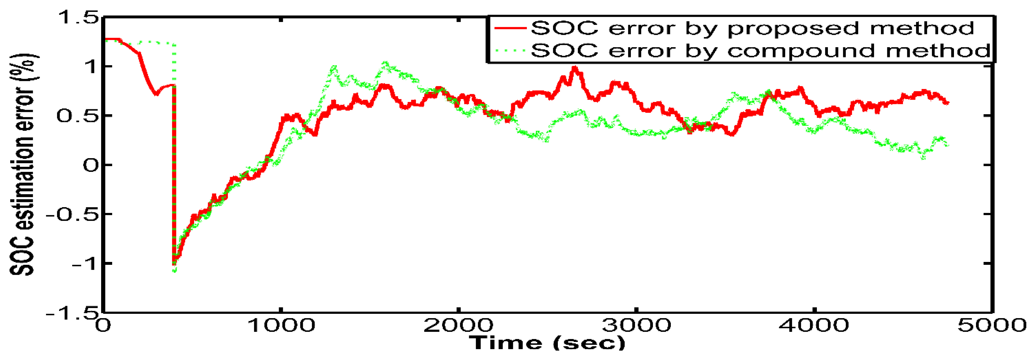
For the first test, the proposed method’s SOC estimation is compared with the SOC estimation error of a method which is a combination of the coulomb counting method and IEKF, which is called compound method and is described here. In the compound method, SOC estimation for initial steps is calculated based on Equation (1). Later on, the IEKF method is used for SOC estimation. In this test, initial SOC of the pack is 67%. This value is retrieved from BMS memory in the beginning of the test.
Figure 9 presents SOC estimation error for charging/discharging current profile of
Figure 5. Mean squared error for the combined method and the proposed method are about 1.15% and 0.83%. Since proposed fuzzy operator is a simple formula and easy to be used in BMS, the proposed method is preferred to compound method. Moreover, the proposed method improves its estimation at each time step and also avoids coulomb counting method’s common disadvantages including accumulative current errors.
For the next test, a normalized New European Driving Cycle (NEDC) current profile was used to evaluate the proposed method. This driving cycle consists of four urban driving profiles followed by another Extra Urban Driving Cycle (EUDC) profile.
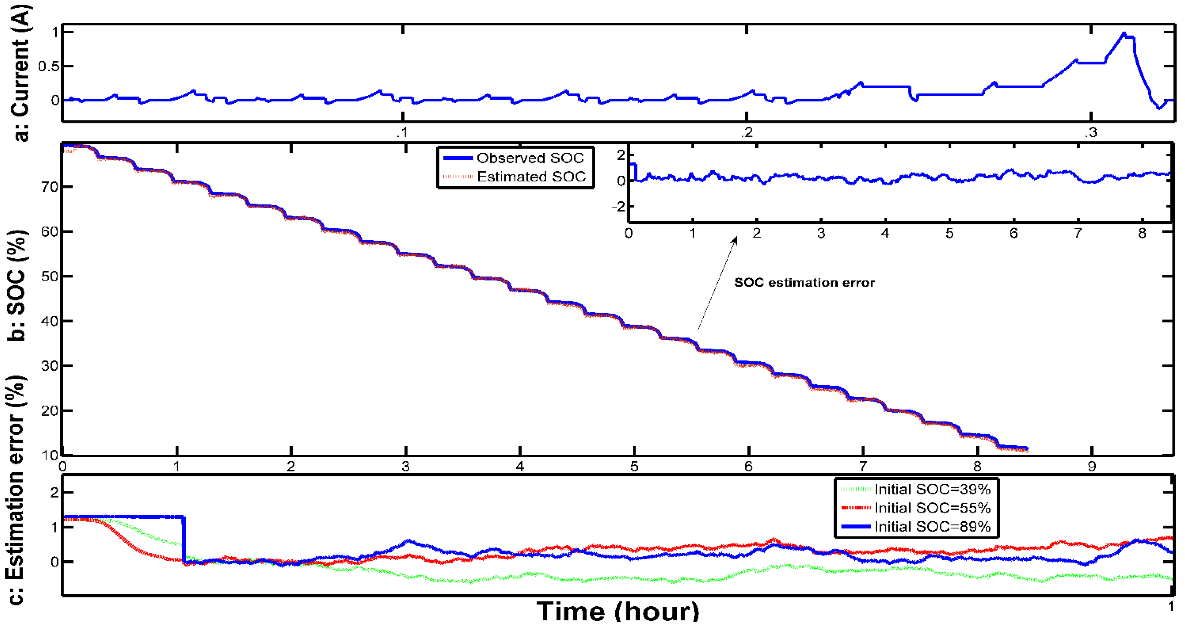
Figure 10a shows the current profile for one cycle. This current profile is continuous without resting time until the pack’s estimated SOC reaches 10%.
Figure 10b shows a reference SOC for the pack and estimated SOC by the proposed method. SOC estimation error is presented in the same figure. In this test, our criteria to stop the test was when the estimated SOC reaches 10%. At this time, the SOC for the weakest cell of the pack was about 9.8% and the highest SOC for a pack cell was 12.4%. These SOCs are still safe and are not considered as over discharged for the pack’s cells. The mean squared error for SOC estimation in this test was about 0.79%.
Figure 10c presents SOC estimation error starting from different initial SOCs (89%, 55% and 39%) for the first hour of charging/discharging based on a current profile as presented in
Figure 10a. For all initial SOC values in
Figure 10c, estimation error converges to zero from initial steps.
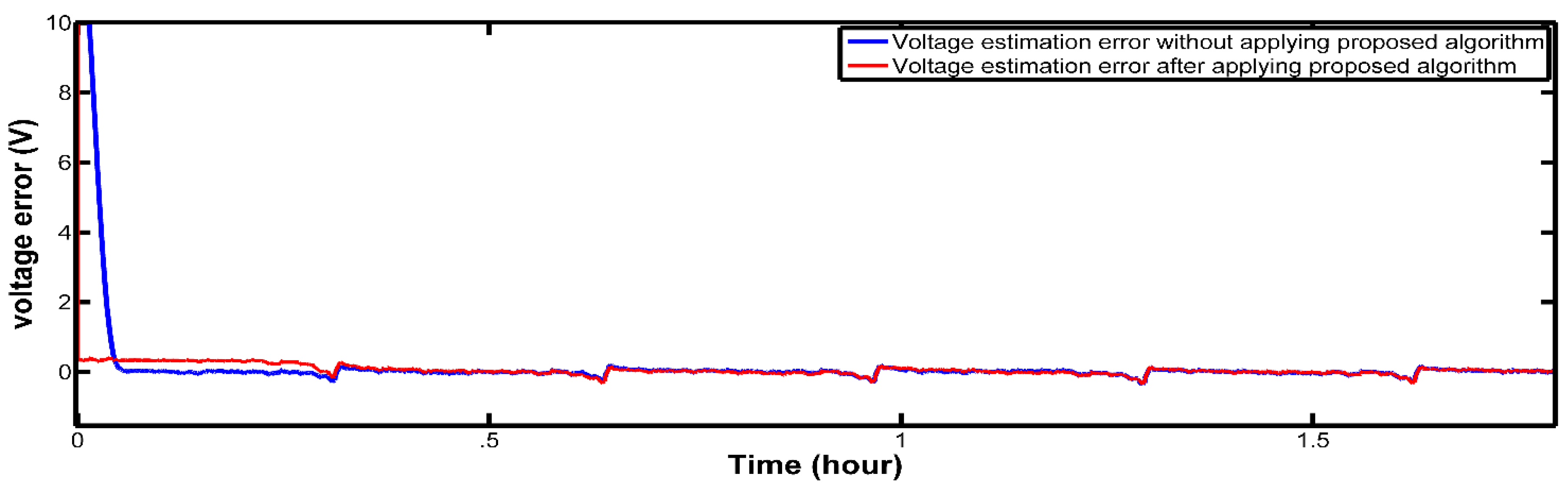
Figure 11 presents estimated voltage error for the battery pack when pack SOC starts from 89%. Since, using the proposed method, SOC estimation error decreases for initial guesses, it would improve the estimated voltage for the battery pack.
Figure 9.
SOC estimation error for the proposed method and the compound method.
Figure 9.
SOC estimation error for the proposed method and the compound method.
Figure 10.
(a) Normalized NEDC current profile; (b) Observed SOC and estimated SOC for the pack by proposed method; (c) SOC estimation error for different initial values.
Figure 10.
(a) Normalized NEDC current profile; (b) Observed SOC and estimated SOC for the pack by proposed method; (c) SOC estimation error for different initial values.
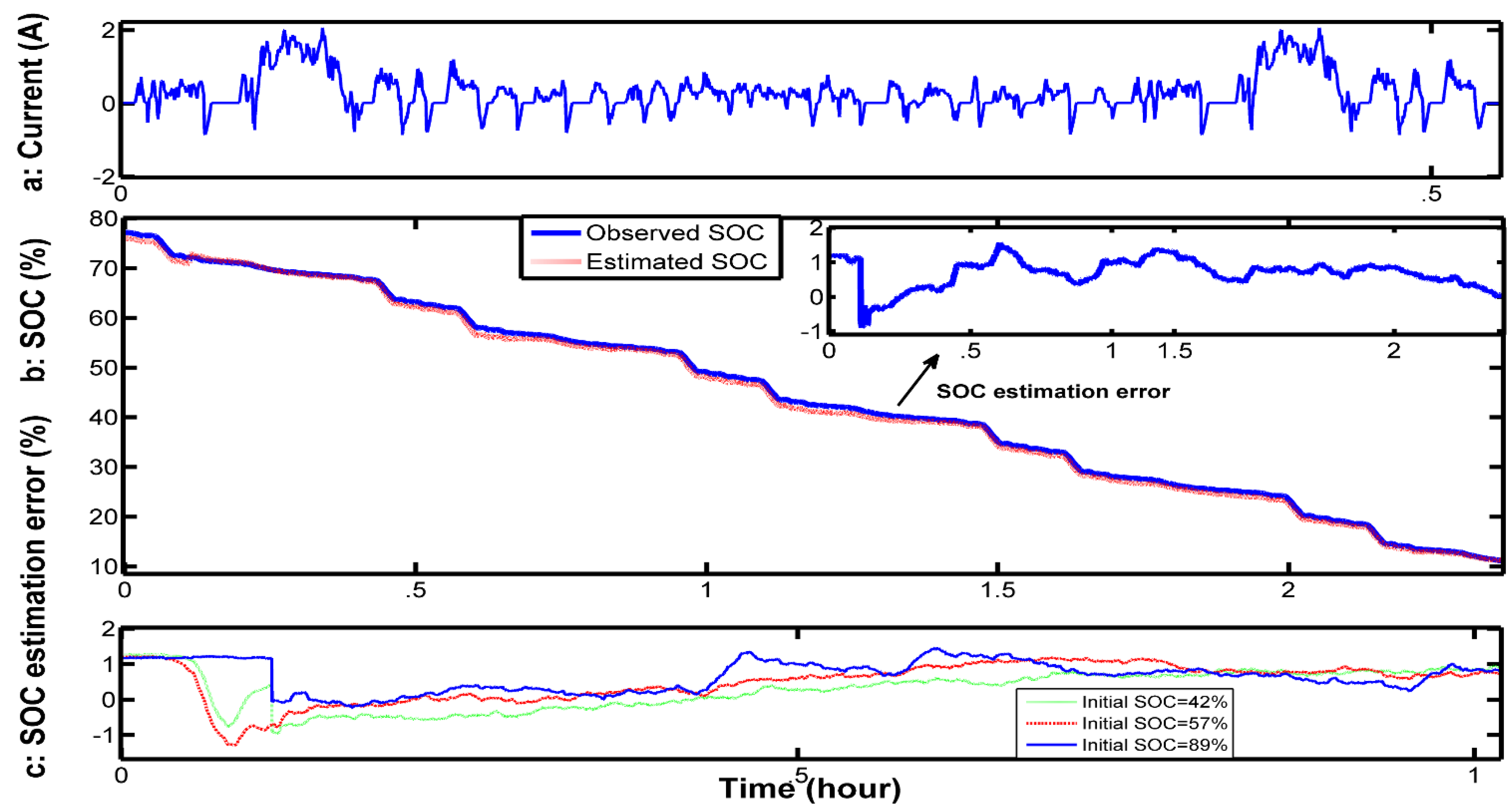
For the last test, a similar analysis with a normalized United States Federal Test Procedure (FTP-75) was designed. FTP-75 is a more realistic driving cycle compared to the NEDC. FTP-75 is known as a transient driving cycle and represents driving in an urban environment with frequent stops [
36]. As in the above test, the current profile is consecutive without any resting time until the pack’s estimated SOC reached 10%. The current profile of one simulation cycle is shown in
Figure 12a. The test was continued with the same current profile until the pack’s estimated SOC reached 10%. The pack’s initial SOC was 76%, which we assume was the latest estimated SOC saved in the BMS. Estimated SOC and SOC estimation error obtained from model adaptive fuzzy-IEKF is depicted in
Figure 12b. The test was stopped when the pack’s SOC reached 10%. At the stopping moment, the SOC for the weakest cell of the pack was about 9.6% and the highest SOC of all cells was 12.2%, which means we can trust the estimated SOC for the pack without having concerns about the weakest cell in the pack. The mean squared error for SOC estimation in this test was about 0.82%.
Figure 12c presents the SOC estimation error starting from different initial SOCs (89%, 57% and 42%) for the first hour of tests.
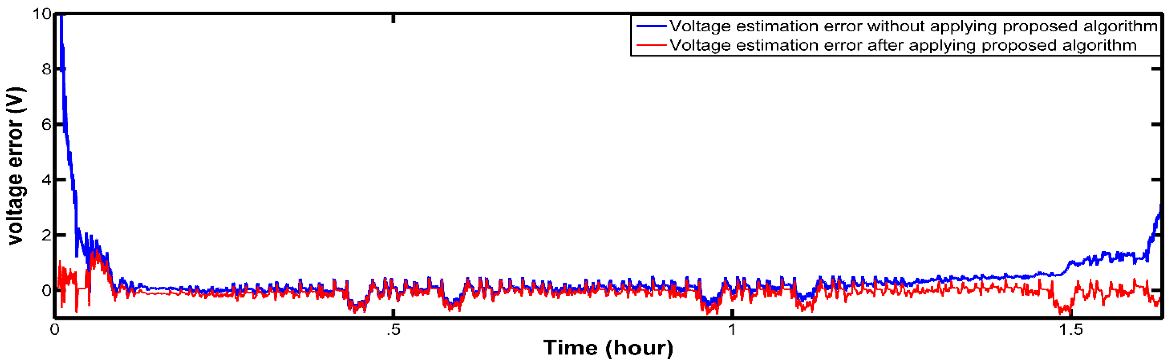
Figure 13 shows the voltage estimation error for the battery pack for two hours before and two hours after applying the proposed algorithm. Initial SOC for the pack calculated by Equation (20) is 89%. It is clear that the proposed algorithm improves the voltage estimation significantly due to the accuracy of the SOC estimation.
Figure 11.
Estimated voltage error of the battery pack for about 2 hours before and after applying proposed method discharging with FTP-75 current profile from initial 89% SOC.
Figure 11.
Estimated voltage error of the battery pack for about 2 hours before and after applying proposed method discharging with FTP-75 current profile from initial 89% SOC.
Figure 12.
(a) Normalized FTP-75 current profile; (b) Observed SOC and estimated SOC for the pack by proposed method; (c) SOC estimation error for different initial values.
Figure 12.
(a) Normalized FTP-75 current profile; (b) Observed SOC and estimated SOC for the pack by proposed method; (c) SOC estimation error for different initial values.
Figure 13.
Estimated voltage error of the battery pack for about 2 hours before and after applying proposed method discharging with FTP-75 current profile from initial 89% SOC.
Figure 13.
Estimated voltage error of the battery pack for about 2 hours before and after applying proposed method discharging with FTP-75 current profile from initial 89% SOC.


