
Advanced Electrical Machines and Machine-Based Systems for Electric and Hybrid Vehicles


Abstract
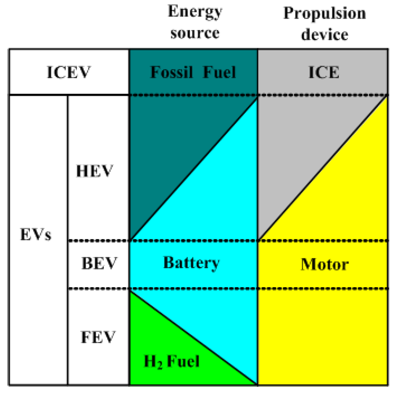
:1. Introduction

2. Electric Vehicle Drive System
- (1)
- High torque density and power density.
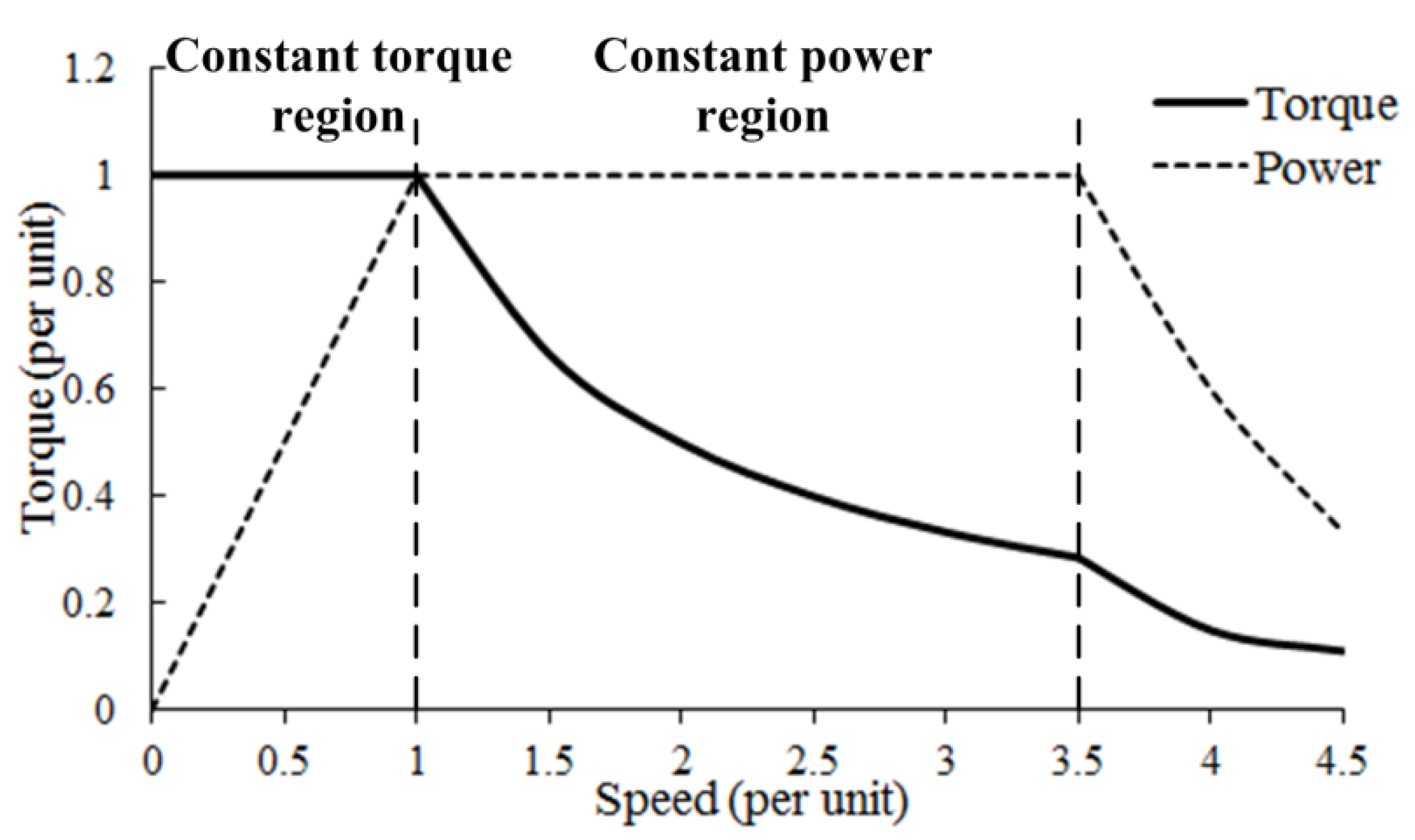
- (2)
- Very wide speed range, for example the speed range of the constant power region should be 3–4-times that of the constant torque region, as shown in Figure 2.
- (3)
- Extended area of high efficiency; it should cover most of the operating regions.
- (4)
- Large torque output at low speeds in order to dispose of enough torque when the vehicle starts or is climbing.
- (5)
- Strong overload capability, for instance the motor can output two-times the rated torque during a short time.
- (6)
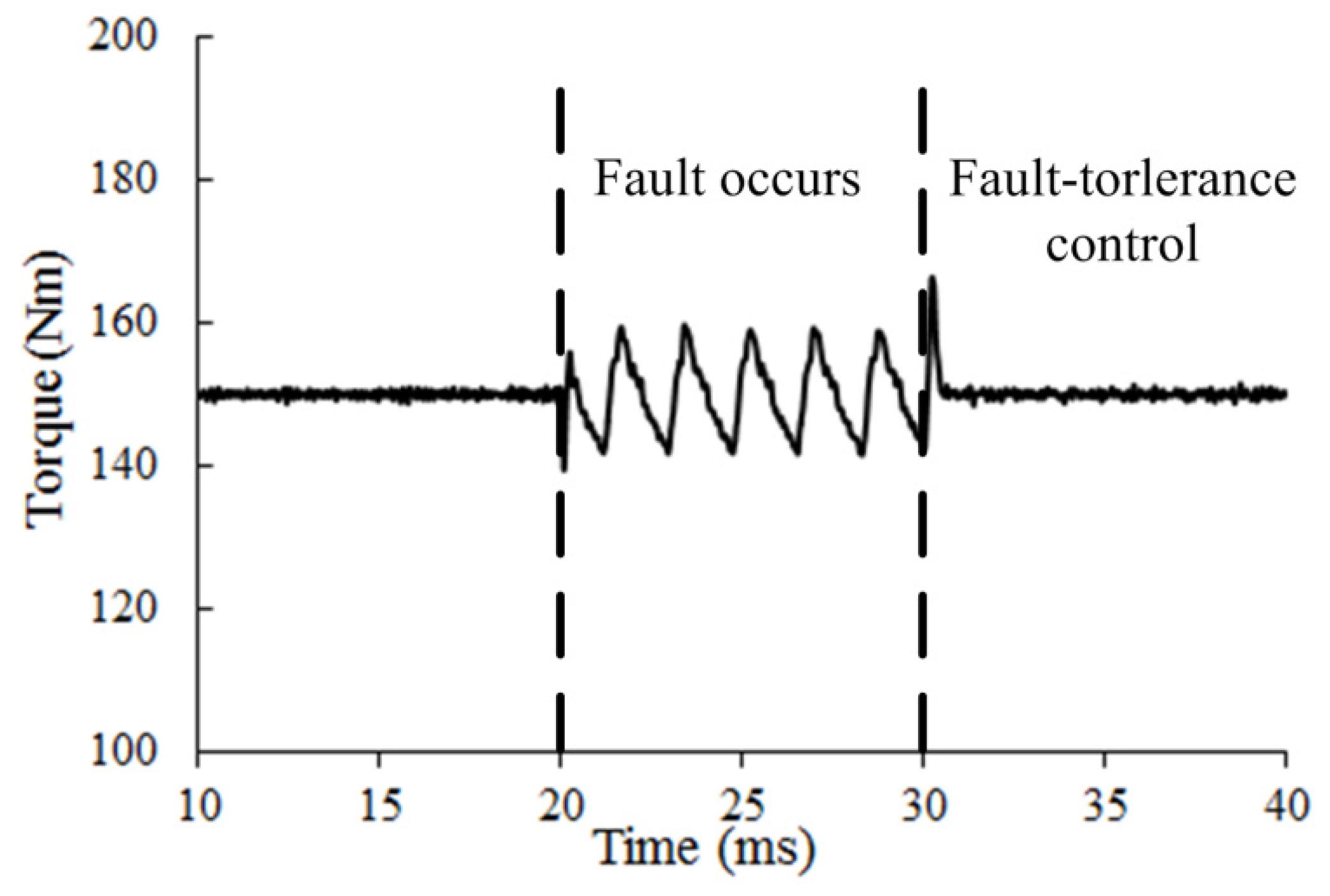
- Security and reliability, for instance fault-tolerant configurations should be arranged.
- (7)
- Motor noise and torque ripple should be suppressed.
- (8)
- Reasonable costs.

| Items | EV motors | Traditional industrial motors |
|---|---|---|
| Ambient temperate | −40~140 °C | 20~40 °C |
| Operation environment | Adverse | Indoor |
| Coolant temperate | 75~150 °C | <40 °C |
| Winding temperate | 160~200 °C | 75~130 °C |
| Speed range | 0~15,000 rpm | <3000 rpm |
| Noise level | Very low | Low |
| Speed demand | Frequent changes | Keep uniform |
| Installation space | Very limited | Loose |
| System voltage | Independent/Variable | Static grid |
| Efficiency | Efficient | Determined by application |


| Motor type | Torque (Nm) | Armature current density (A/mm2) | Efficiency (%) |
|---|---|---|---|
| 1500 r/min | |||
| PMSM(Prius) | 303 | 15.7 | 91.3 |
| SRM | 297 | 15.8/12.1 | 83.1 |
| IM | 294 | 20.1 | 85.2 |
| 6000 r/min | |||
| PMSM(Prius) | 45.6 | 3.75 | 96.1 |
| SRM | 50.8 | 4.51/3.72 | 95.2 |
| IM | 52.1 | 4.02 | 88.2 |
3. Advanced Motor Topologies
3.1. Stator Permanent Magnet Motor

3.1.1. Doubly-Salient PM Motor (DSPM)
3.1.2. Flux Switching PM Motor (FSPM)


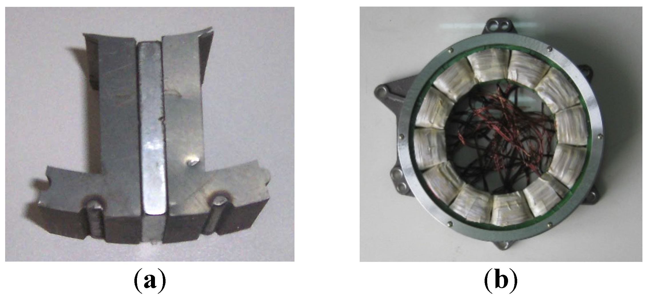
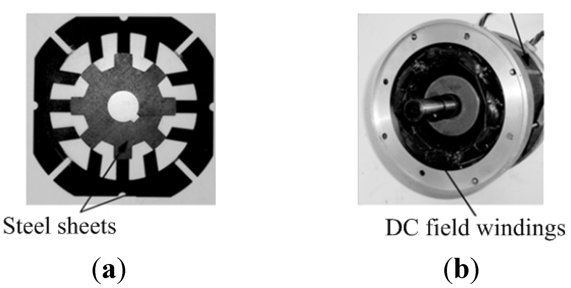
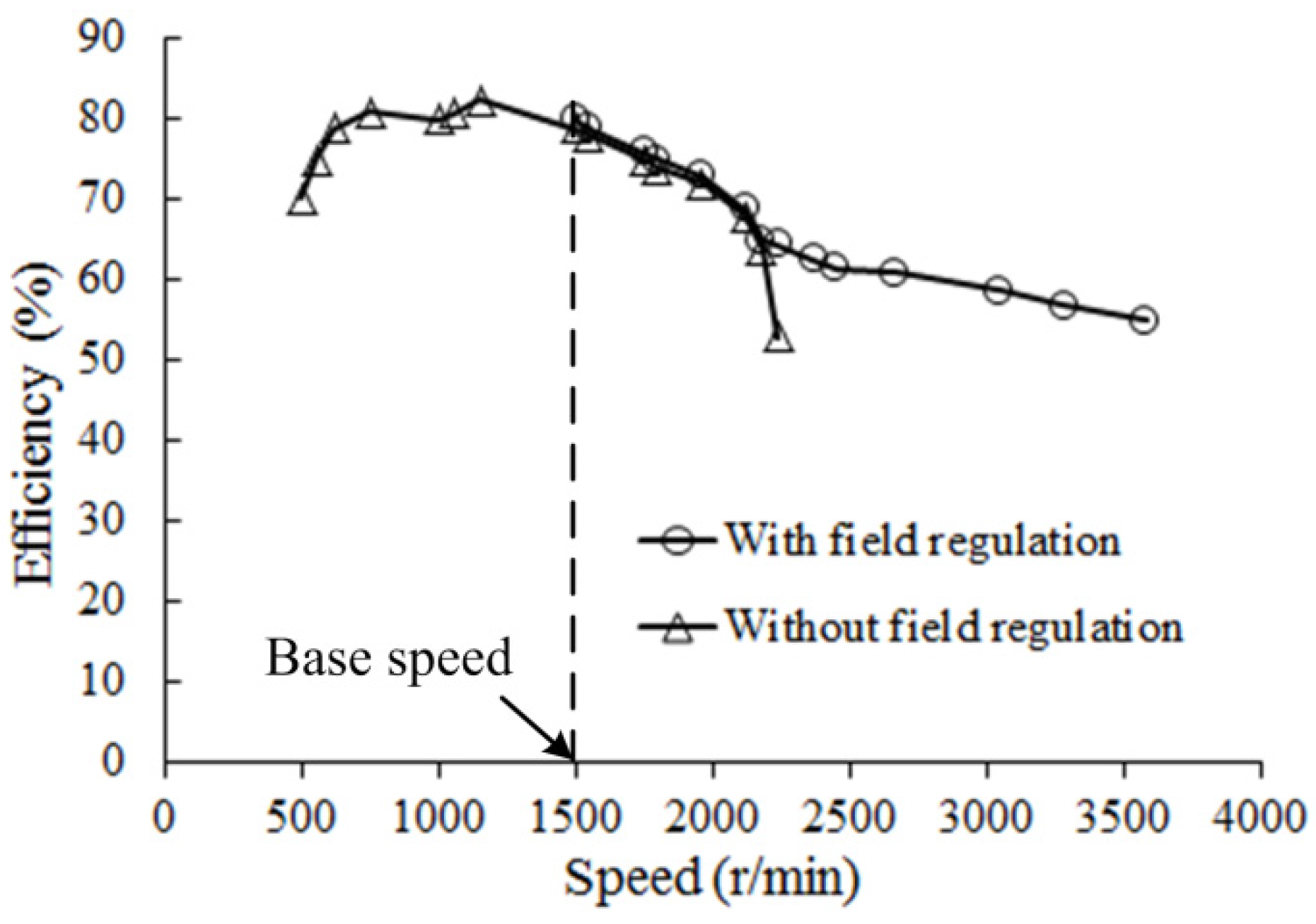
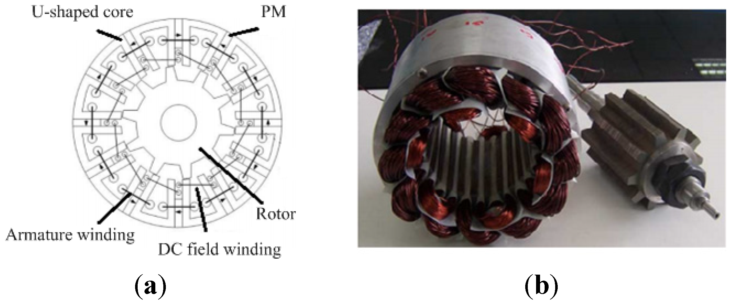
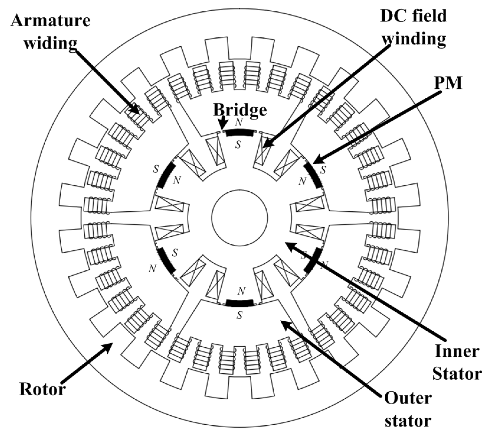
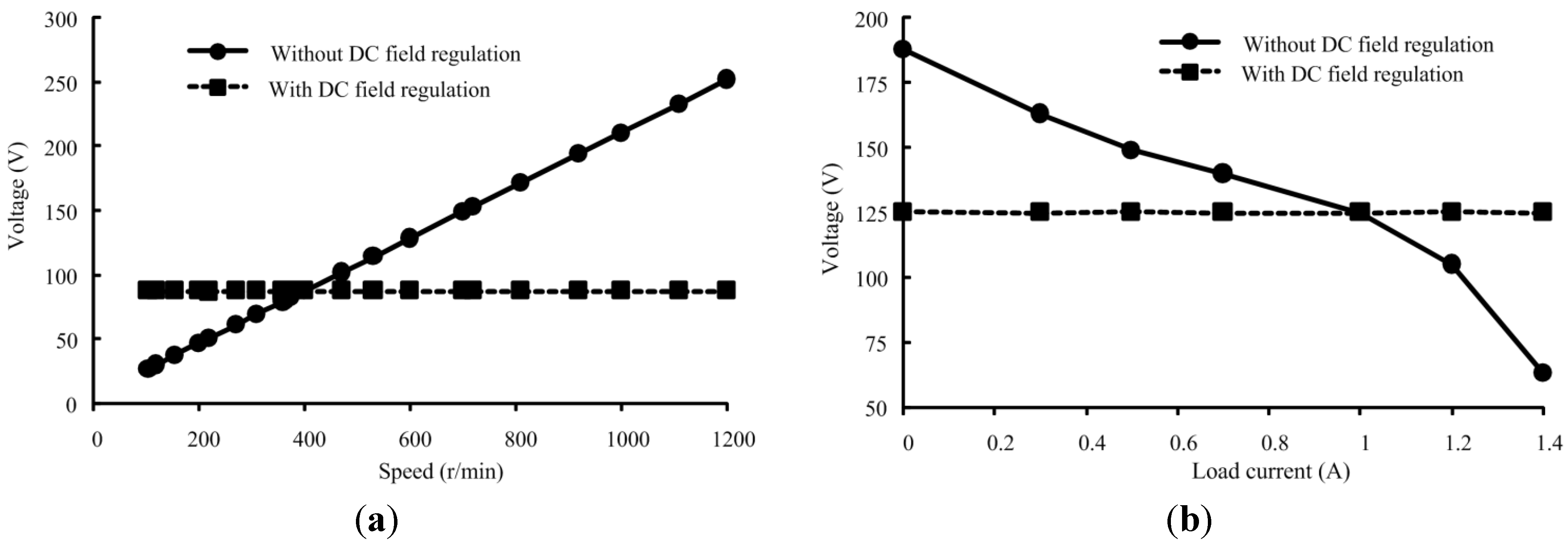
3.2. Hybrid-Excitation Motor


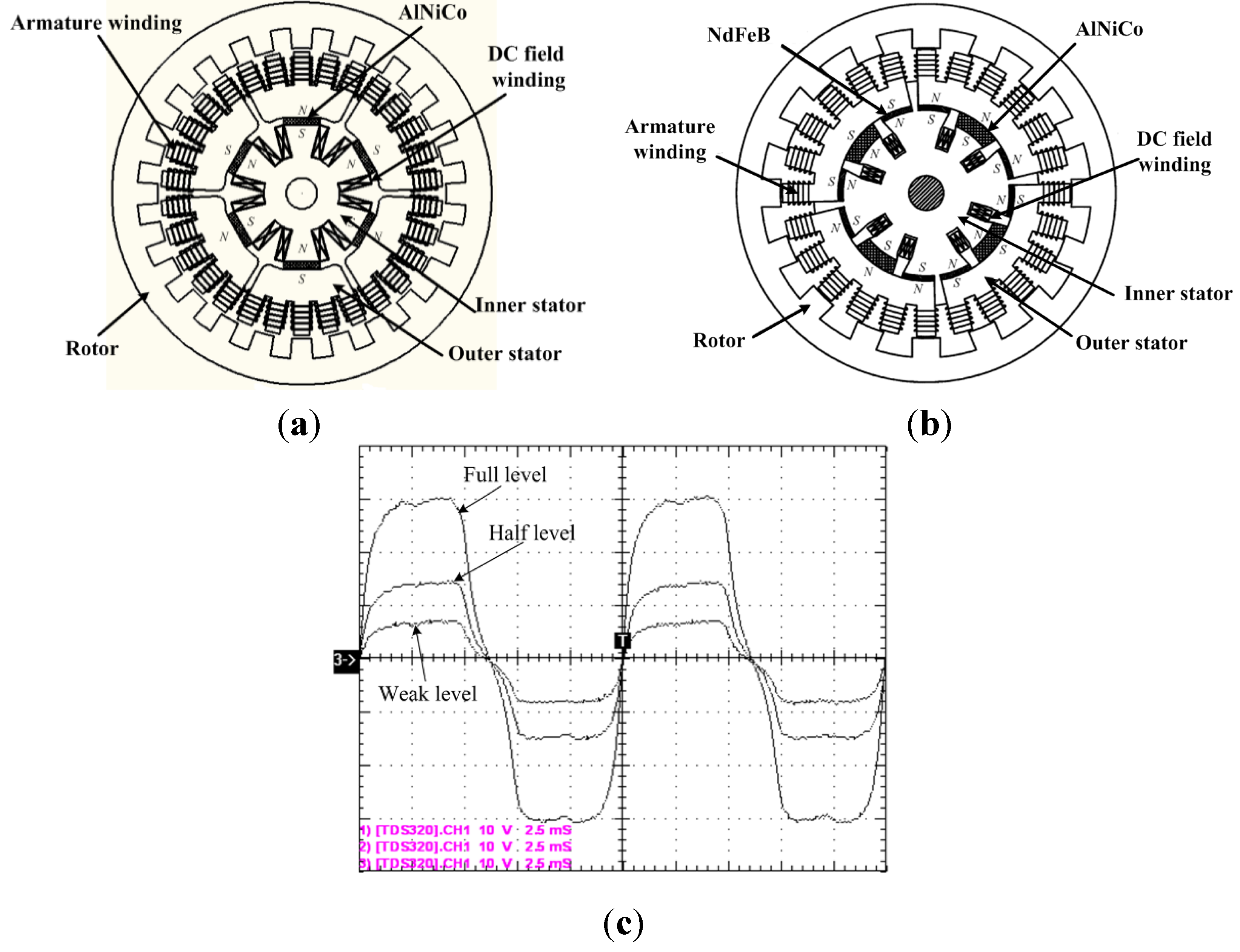
3.3. Flux Memory Motor

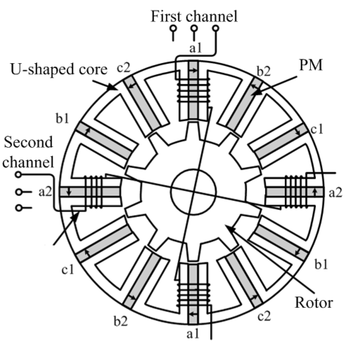
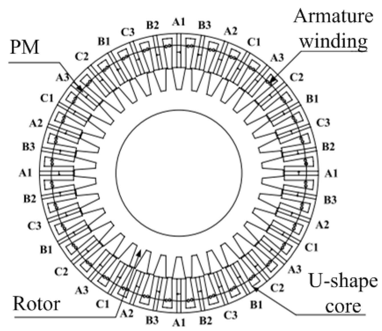
3.4. Redundant Structure and Fault-Tolerance Control


| Motor topology | Stator-PM motors | Hybrid-excitation motor | Flux memory motor | ||
|---|---|---|---|---|---|
| DSPM | FSPM | FRPM | |||
| Stator | Salient poles with both PM and armature windings | ||||
| Rotor | Salient poles with neither magnets nor windings | ||||
| Magnet location | Stator | ||||
| Magnet volume | Low | Medium | High | Lower than PM counterpart | Similar to PM counterpart |
| Magnet material | NdFeB | NdFeB | NdFeB | NdFeB | AlNiCo |
| Field winding | - | - | - | Stator | Stator |
| Field coil loss | - | - | - | High | Negligible |
| Flux controllability | Low | Low | Low | High | High |
| Speed range | Limited | Limited | Limited | Wide | Wide |
| Torque Density | Low | Low | High | Medium | Medium |
4. Advanced Electric Drive System
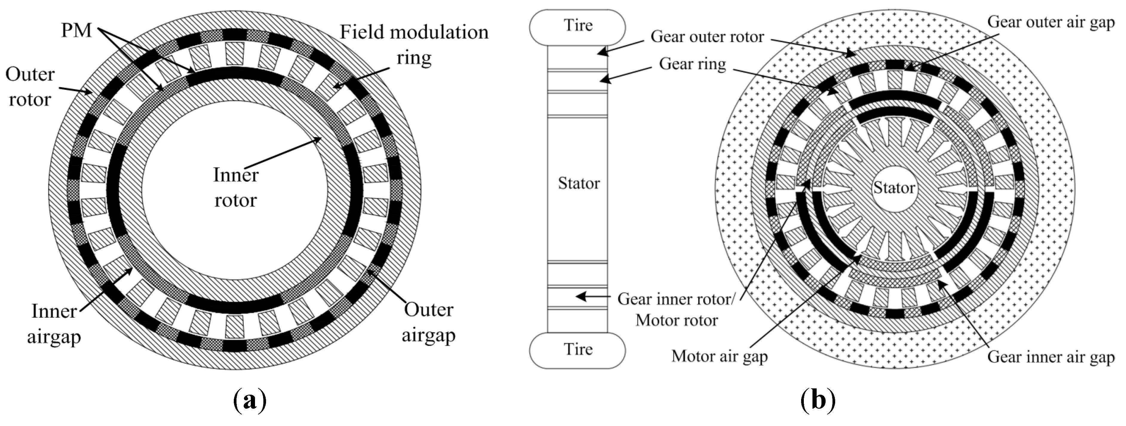
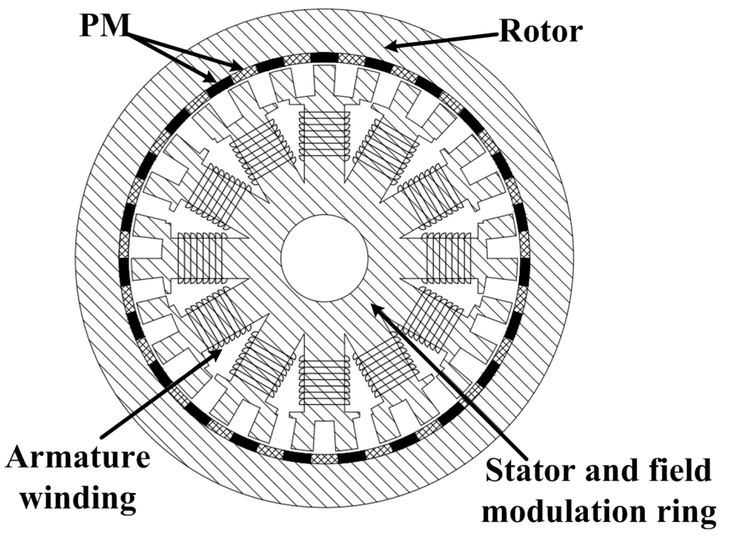
4.1. Magnetic-Geared In-Wheel Drive System


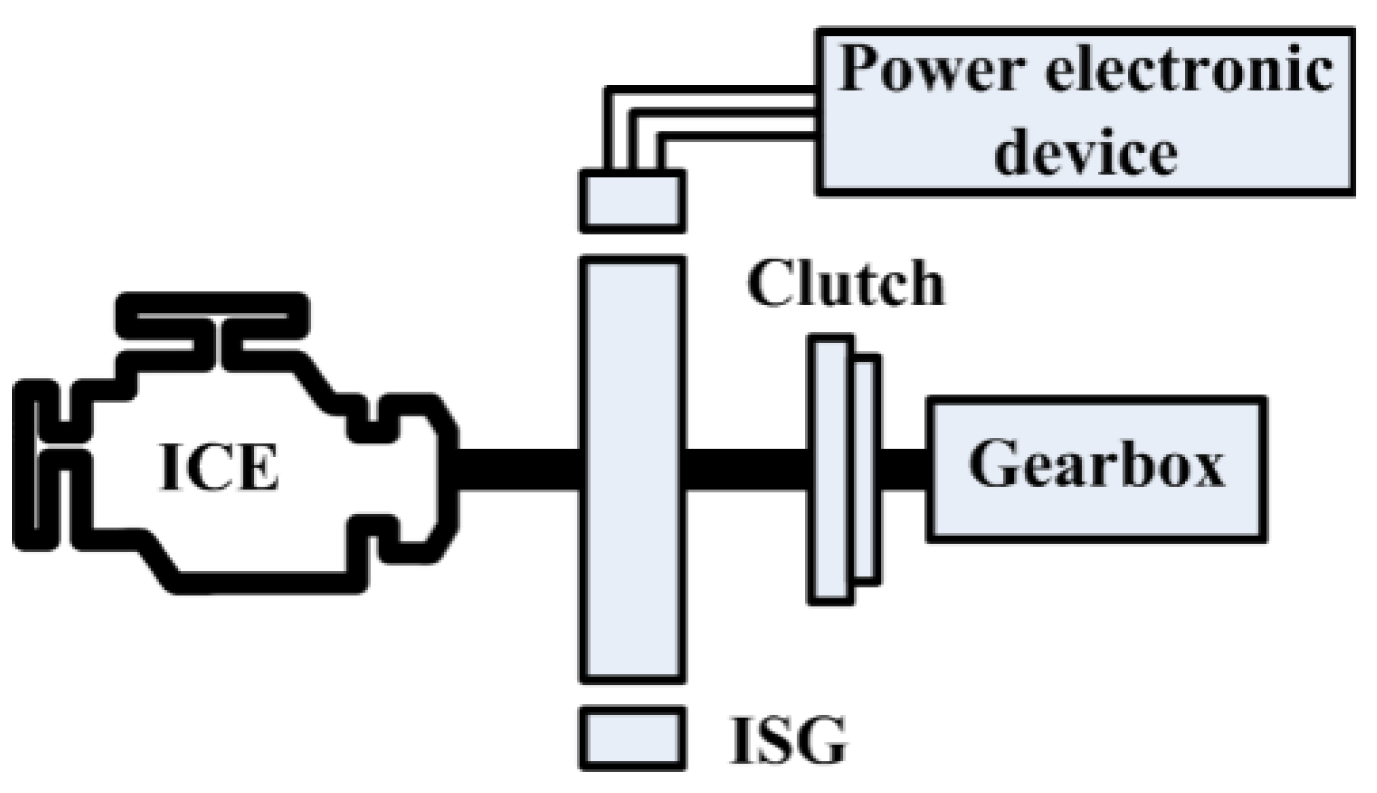
4.2. ISG System Based on the PM Motor


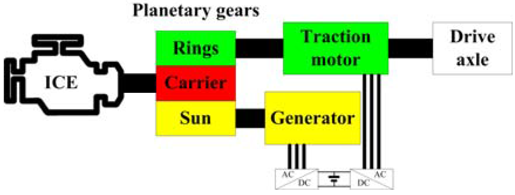
5. Power Distribution System for an HEV

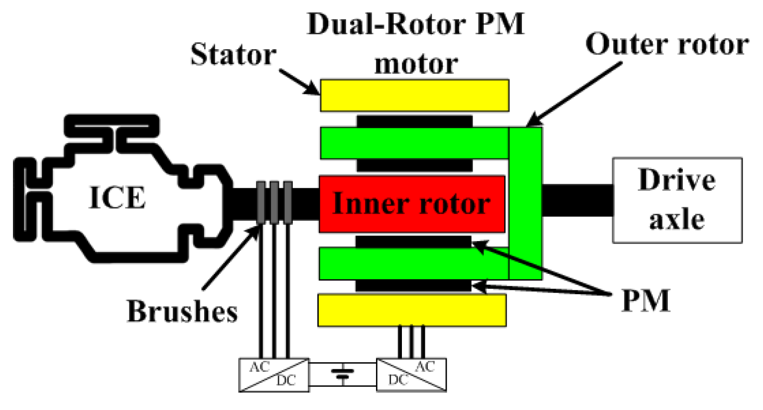
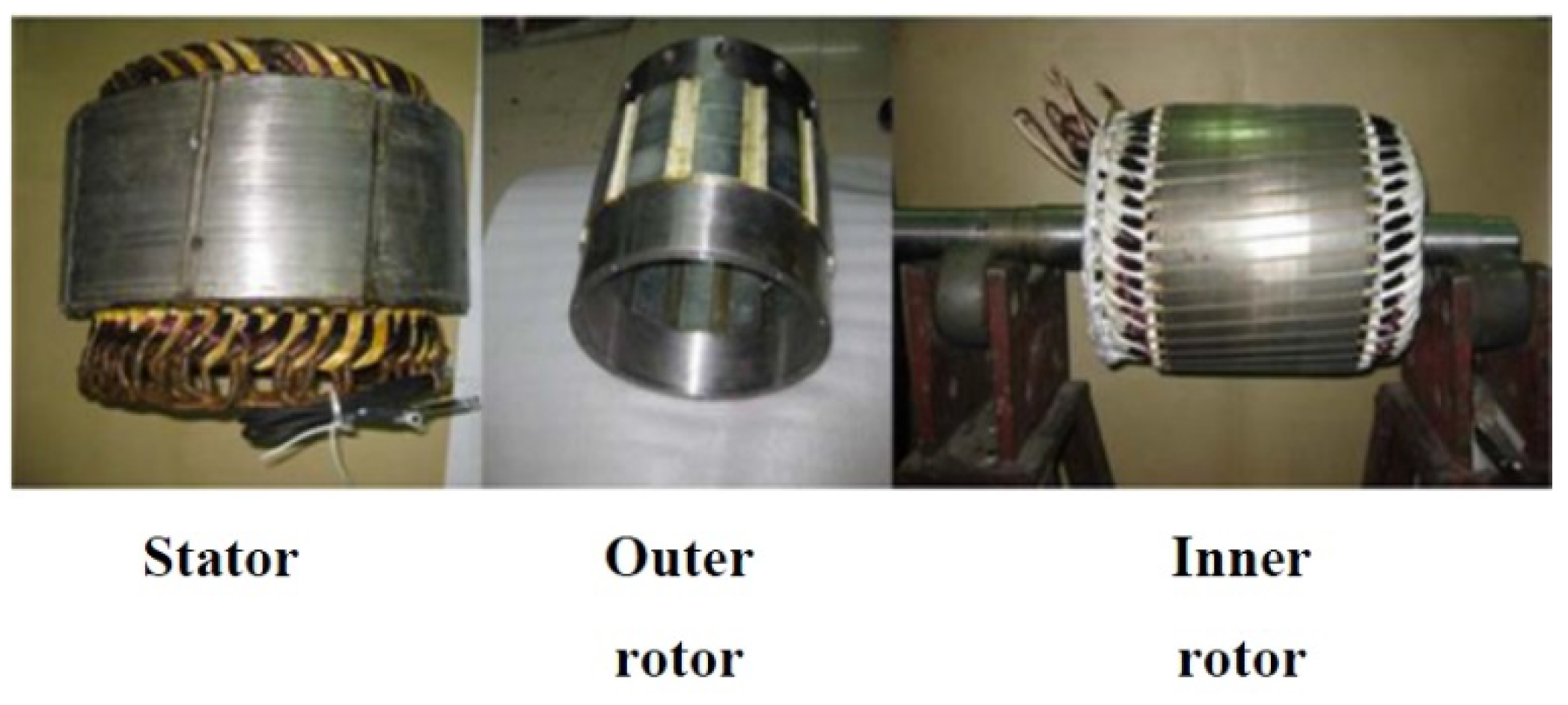
5.1. Dual-Rotor PM ECVT


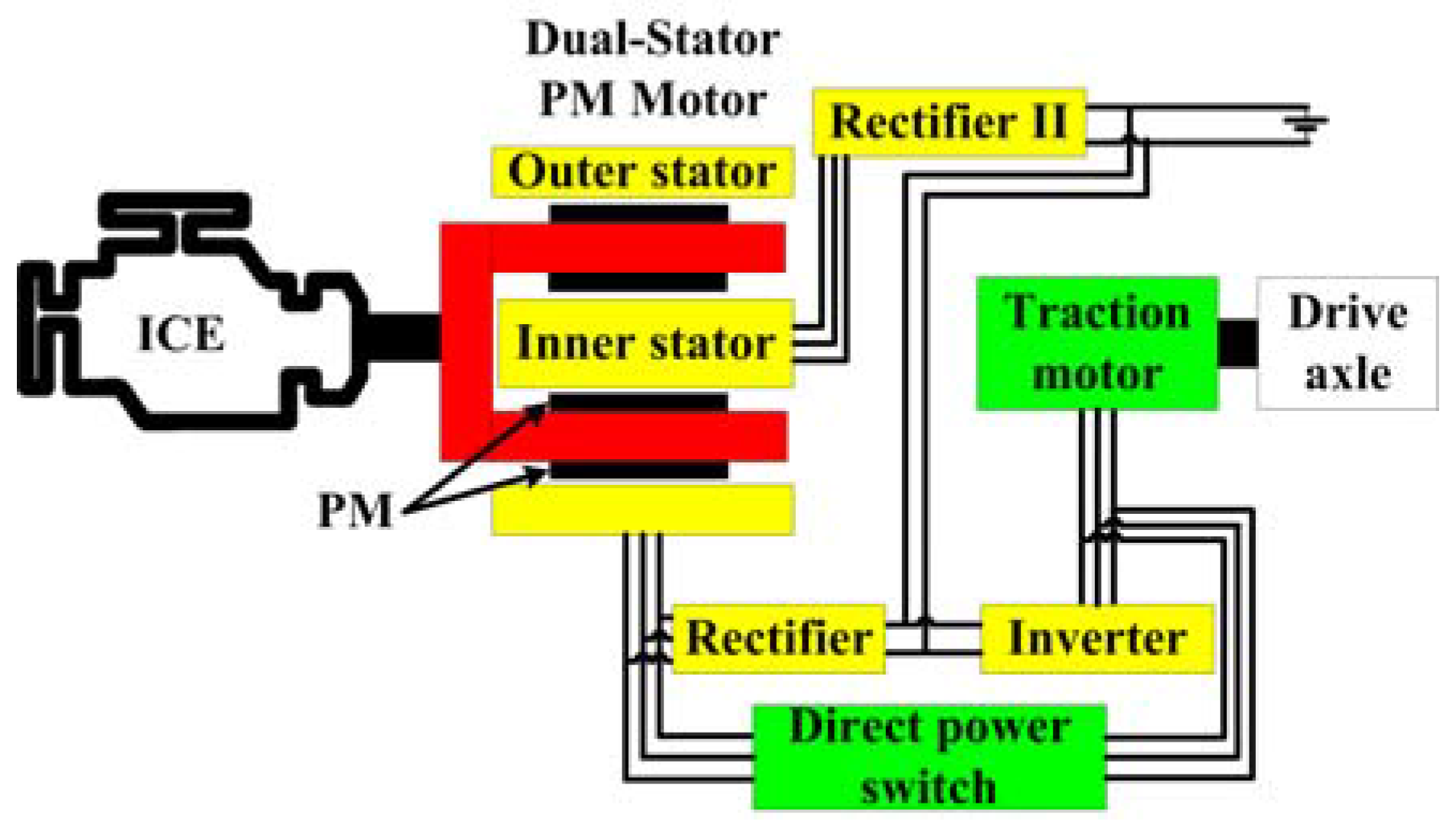
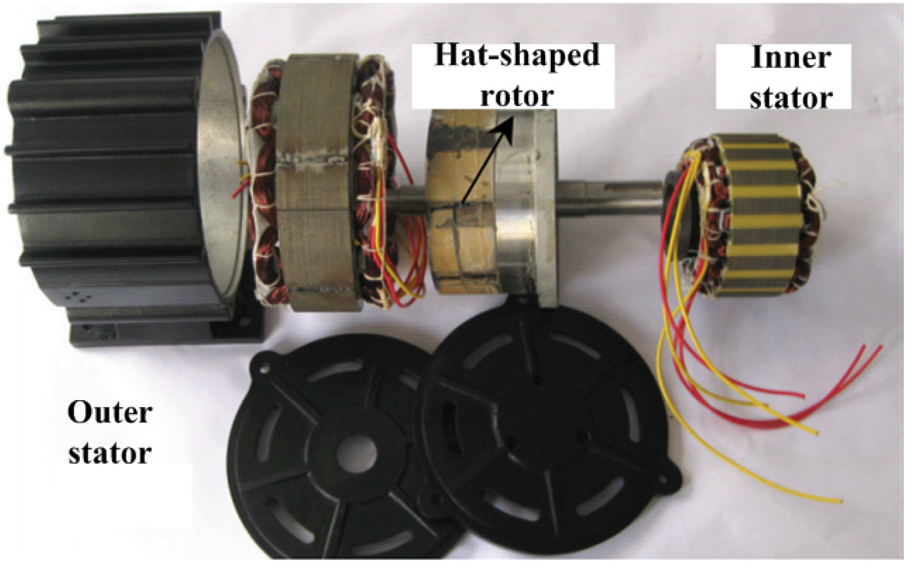
5.2. Dual-Stator PM Brushless ECVT


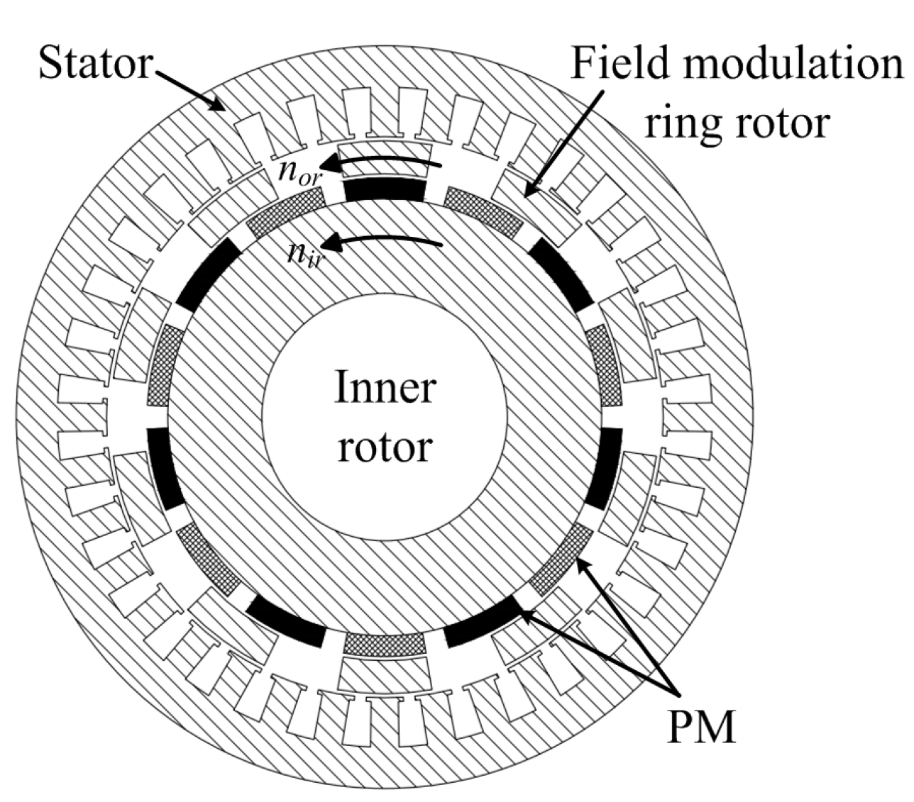
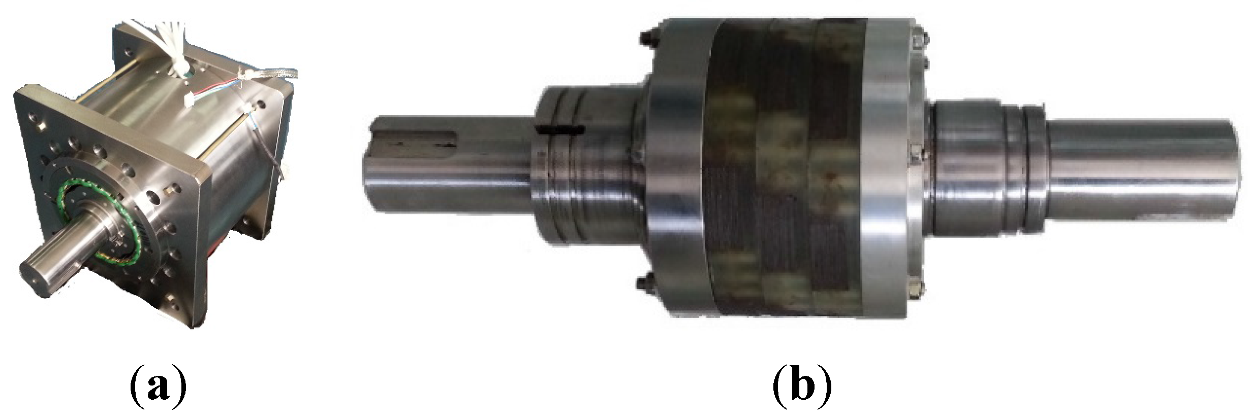
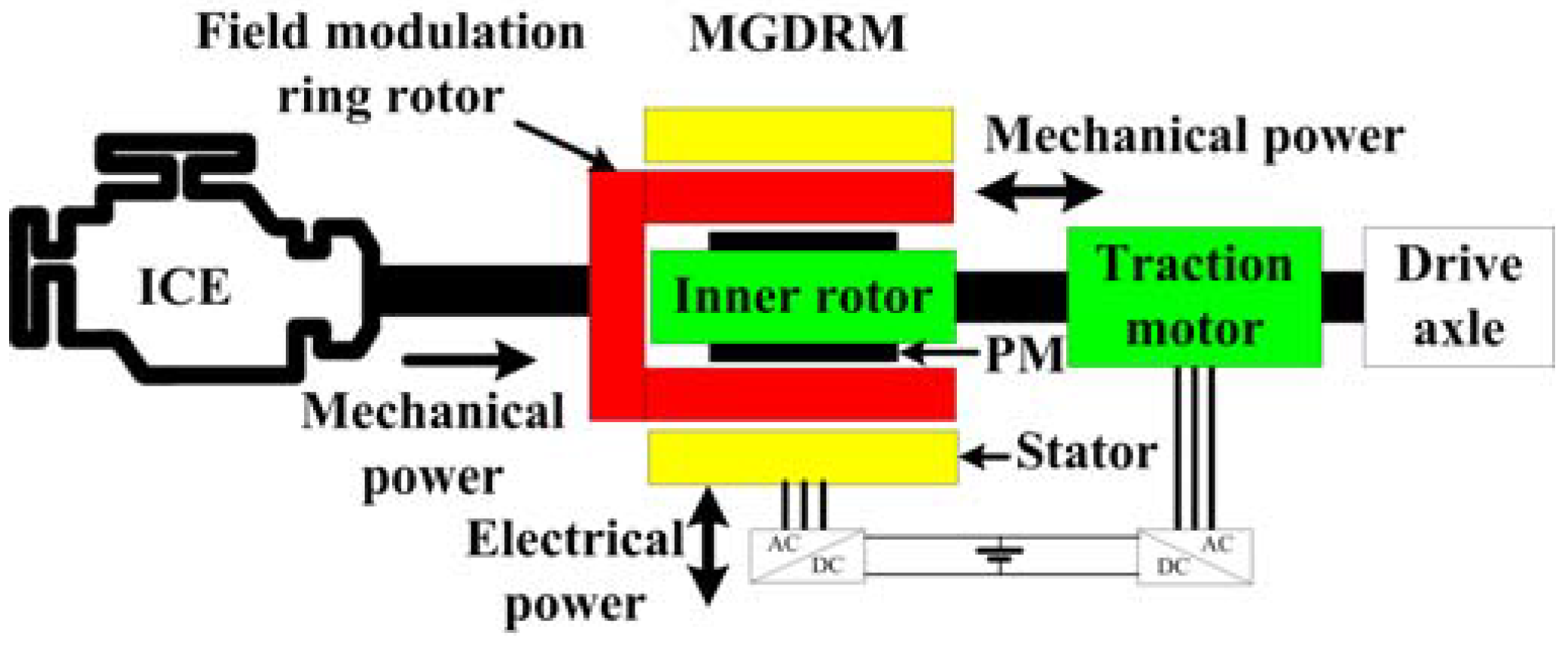
5.3. Dual-Rotor Magnetic-Geared Brushless ECVT


| ECVT topology | Dual-rotor PM | Dual-stator PM | Magnetic-geared |
|---|---|---|---|
| Stator number | 1 | 2 | 1 |
| Rotor number | 2 | 1 | 2 |
| Winding number | 2 | 2 | 1 |
| Brush | Yes | No | No |
| Converter number | 2 | 4 | 2 |
| Magnet amount | Low | High | Low |
| Copper amount | High | High | Low |
| Torque density | Medium | Medium | High |
6. Conclusions and Developing Trends
- (i)
- Motor level: various novel motor topologies and control algorithm may be proposed to satisfy the specific requirements of EV motors.
- (ii)
- Drive system level: a novel electric drive system with advanced performance should be developed to replace the mechanical gear and transmission axle by electric technology and to achieve the full electrification of the powertrain.
- (iii)
- Powertrain level: the optimized design of the operation patterns for the electrified powertrain, especially for HEVs and plug-in HEVs with ECVT, should be pursued to enhance the energy economy of the vehicles.
- (iv)
- Whole vehicle level: to minimize the overall cost and weight of the vehicle, the motor drive system may be integrated with other electric devices. A motor drive system integrated with a charger for a plug-in HEV is just an example.
Acknowledgments
Author Contributions
Conflicts of Interest
References
- Chan, C.C.; Chau, K.T. Modern Electric Vehicle Technology, 1st ed.; Oxford University Press: New York, NY, USA, 2001; pp. 16–28. [Google Scholar]
- Cheng, M.; Chan, C.C. General requirement of traction motor drives. Encycl. Automot. Eng. 2015, 3, 1261–1278. [Google Scholar]
- Chan, C.C.; Chau, K.T. An overview of power electronics in electric vehicles. IEEE Trans. Ind. Electron. 1997, 44, 3–13. [Google Scholar] [CrossRef] [Green Version]
- Zhu, Z.Q.; Howe, D. Electrical machines and drives for electric, hybrid, and fuel cell vehicles. Proc. IEEE 2007, 95, 746–765. [Google Scholar] [CrossRef]
- Dorrell, D.G.; Knight, A.M.; Popescu, M.; Evans, L.; Staton, D.A. Comparison of different motor design drives for hybrid electric vehicles. In Proceedings of the IEEE Energy Conversion Congress and Exposition (ECCE), Atlanta, GA, USA, 12–16 September 2010; pp. 3352–3359.
- Cheng, M.; Hua, W.; Zhang, J.; Zhao, W. Overview of stator-permanent magnet brushless machines. IEEE Trans. Ind. Electron. 2011, 58, 5087–5101. [Google Scholar] [CrossRef]
- Liao, Y.; Liang, F.; Lipo, T.A. A novel permanent magnet machine with doubly salient structure. IEEE Trans. Ind. Appl. 1995, 31, 1069–1078. [Google Scholar] [CrossRef]
- Cheng, M.; Chau, K.T.; Chan, C.C. Static characteristics of a new doubly salient permanent magnet motor. IEEE Trans. Energy Convers. 2001, 16, 20–25. [Google Scholar] [CrossRef] [Green Version]
- Cheng, M.; Chau, K.T.; Chan, C.C. Design and analysis of a new doubly salient permanent magnet motor. IEEE Trans. Magn. 2001, 37, 3012–3020. [Google Scholar] [CrossRef] [Green Version]
- Zhang, J.; Cheng, M.; Chen, Z.; Hua, W. Comparison of stator-mounted permanent magnet machines based on a general power equation. IEEE Trans. Energy Convers. 2009, 24, 826–834. [Google Scholar] [CrossRef]
- Cheng, M.; Chau, K.T.; Chan, C.C.; Zhou, E.; Huang, X. Nonlinear varying-network magnetic circuit analysis for doubly salient permanent magnet motors. IEEE Trans. Magn. 2000, 36, 339–348. [Google Scholar] [CrossRef] [Green Version]
- Zhang, J.; Wang, M.; Cheng, M. Prediction of iron losses in doubly salient permanent magnet machine with rectangular current waveform. J. Appl. Phys. 2012, 111, 07E716. [Google Scholar] [CrossRef]
- Zhu, S.; Cheng, M.; Dong, J.; Du, J. Core loss analysis and calculation of stator permanent magnetmachine considering DC-biased magnetic induction. IEEE Trans. Ind. Electron. 2014, 61, 5203–5212. [Google Scholar] [CrossRef]
- Zhu, Z.Q.; Chen, J.T. Advanced flux-switching permanent magnet brushless machines. IEEE Trans. Magn. 2010, 46, 1447–1453. [Google Scholar] [CrossRef]
- Hua, W.; Cheng, M.; Zhu, Z.Q.; Howe, D. Analysis and optimization of back EMF waveform of a flux-switching permanent magnet motor. IEEE Trans. Energy Convers. 2008, 23, 727–733. [Google Scholar] [CrossRef]
- Hua, W.; Cheng, M. Cogging torque reduction of flux-switching permanent magnet machines without skewing. In Proceedings of the International Conference on Electrical Machines and Systems (ICEMS 2008), Wuhan, China, 17–20 October 2008; pp. 3020–3025.
- Jia, H.; Cheng, M.; Hua, W.; Zhao, W.; Li, W. Torque ripple suppression in flux-switching PM motor by harmonic current injection based on voltage space-vector modulation. IEEE Trans. Magn. 2010, 46, 1527–1530. [Google Scholar] [CrossRef]
- Hua, W.; Cheng, M.; Zhu, Z.Q. Design of flux-switching permanent magnet machine considering the limitation of inverter and flux-weakening capability. In Proceedings of the Conference Record of the 2006 IEEE Industry Applications Conference (41st IAS Annual Meeting), Tampa, FL, USA, 8–12 October 2006; pp. 2403–2410.
- Hua, W.; Zhang, G.; Cheng, M. Investigation and design of a high power flux-switching permanent magnet machine for hybrid electric vehicles. IEEE Trans. Magn. 2015, 51, 8201805. [Google Scholar] [CrossRef]
- Chen, J.T.; Zhu, Z.Q.; Iwasaki, S.; Deodhar, R.P. Influence of slot opening on optimal stator and rotor pole combination and electromagnetic performance of switched-flux PM brushless AC machines. IEEE Trans. Ind. Appl. 2011, 47, 1681–1691. [Google Scholar] [CrossRef]
- Chen, J.T.; Zhu, Z.Q. Influence of the rotor pole number on optimal parameters in flux-switching PM brushless AC machines by the lumped-parameter magnetic circuit model. IEEE Trans. Ind. Appl. 2010, 46, 1381–1388. [Google Scholar] [CrossRef]
- Chen, J.T.; Zhu, Z.Q. Winding configurations and optimal stator and rotor pole combination of flux-switching PM brushless AC machines. IEEE Trans. Energy Convers. 2010, 25, 293–302. [Google Scholar] [CrossRef]
- Zhang, G.; Cheng, M.; Hua, W. Analysis of flux-switching permanent magnet machine by nonlinear magnetic network model with bypass-bridges. In Proceedings of the 2010 International Conference on Electrical Machines and Systems (ICEMS), Incheon, Korea, 10–13 October 2010; pp. 1787–1791.
- Cao, R.; Mi, C.; Cheng, M. Quantitative comparison of flux-switching permanent magnet motors with interior permanent magnet motor for EV, HEV, and PHEV applications. IEEE Trans. Magn. 2012, 48, 2374–2384. [Google Scholar] [CrossRef]
- Nalepa, R.; Kowalska, T.O. Optimum trajectory control of the current vector of a nonsalient-pole PMSM in the field-weakening region. IEEE Trans. Ind. Electron. 2012, 59, 2867–2876. [Google Scholar] [CrossRef]
- EL-Refaie, A.M.; Jahns, T.M. Optimal flux weakening in surface PM machines using fractional-slot concentrated windings. IEEE Trans. Ind. Appl. 2005, 41, 790–800. [Google Scholar] [CrossRef]
- Zhu, X.; Cheng, M.; Zhao, W.; Liu, C.; Chau, K.T. A transient cosimulation approach to performance analysis of hybrid excited doubly salient machine considering indirect field-circuit coupling. IEEE Trans. Magn. 2007, 43, 2558–2560. [Google Scholar] [CrossRef] [Green Version]
- Dong, G.; Cheng, M.; Hua, W. Modeling of a novel hybrid-excited flux-switching machine drives for hybrid electrical vehicles. In Proceedings of the 2010 International Conference on Electrical Machines and Systems (ICEMS), Incheon, Korea, 10–13 October 2010; pp. 839–843.
- Zhu, X.; Cheng, M. Design analysis and control of hybrid excited doubly salient stator-permanent magnet motor. Sci. China Technol. Sci. 2010, 53, 188–199. [Google Scholar] [CrossRef]
- Shu, Y.; Cheng, M.; Kong, X. Online efficiency optimization of stator-doubly-fed doubly salient motor based on a loss model. In Proceedings of the International Conference on Electrical Machines and Systems (ICEMS 2008), Wuhan, China, 17–20 October 2008; pp. 1174–1178.
- Hua, W.; Cheng, M.; Zhang, G. A novel hybrid excitation flux-switching motor for hybrid vehicles. IEEE Trans. Magn. 2009, 45, 4728–4731. [Google Scholar] [CrossRef]
- Wang, Y.; Deng, Z. Hybrid excitation topologies and control strategies of stator permanent magnet machines for DC power system. IEEE Trans. Ind. Electron. 2012, 59, 4601–4616. [Google Scholar] [CrossRef]
- Hua, W.; Zhang, G.; Cheng, M. Flux-regulation theories and principles of hybrid-excited flux-switching machines. IEEE Trans. Ind. Electron. 2015, 62, 5359–5369. [Google Scholar] [CrossRef]
- Ostovic, V. Memory motors. IEEE Ind. Appl. Mag. 2003, 9, 52–61. [Google Scholar] [CrossRef]
- Gong, Y.; Chau, K.T.; Jiang, J.Z.; Yu, C.; Li, W. Analysis of doubly salient memory motors using Preisach theory. IEEE Trans. Magn. 2009, 45, 4676–4679. [Google Scholar] [CrossRef] [Green Version]
- Yu, C.; Chau, K.T. Design, analysis, and control of DC-excited memory motors. IEEE Trans. Energy Convers. 2011, 26, 479–489. [Google Scholar] [CrossRef] [Green Version]
- Yu, C.; Chau, K.T. Dual-mode operation of DC-excited memory motors under flux regulation. IEEE Trans. Ind. Appl. 2011, 47, 2031–2041. [Google Scholar] [CrossRef] [Green Version]
- Zhu, X.; Quan, L.; Chen, D.; Cheng, M.; Hua, W.; Sun, X. Electromagnetic performance analysis of a new stator-permanent magnet doubly salient flux memory motor using a piecewise-linear hysteresis model. IEEE Trans. Magn. 2011, 47, 1106–1109. [Google Scholar] [CrossRef]
- EL-Refaie, A.M. Fault-tolerant permanent magnet machines a review. IET Electr. Power Appl. 2011, 5, 59–74. [Google Scholar] [CrossRef]
- Zhao, W.; Cheng, M.; Zhu, X.; Hua, W.; Kong, X. Analysis of fault-tolerant performance of a doubly salient permanent magnet motor drive using transient cosimulation method. IEEE Trans. Ind. Electron. 2008, 55, 1739–1748. [Google Scholar] [CrossRef]
- Zhao, W.; Chau, K.T.; Cheng, M.; Ji, J.; Zhu, X. Remedial brushless AC operation of fault-tolerant doubly salient permanent magnet motor drives. IEEE Trans. Ind. Electron. 2010, 57, 2134–2141. [Google Scholar] [CrossRef] [Green Version]
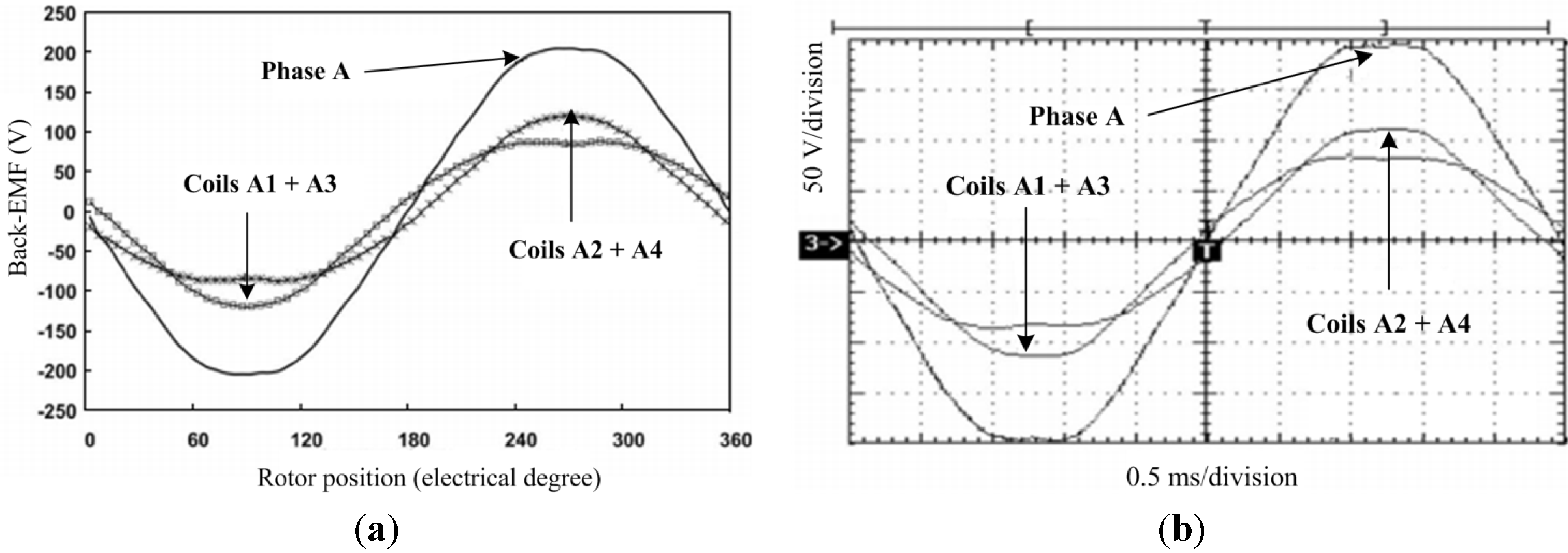
- Zhao, W.; Cheng, M.; Hua, W.; Jia, H.; Cao, R. Back-EMF harmonic analysis and fault-tolerant control of flux-switching permanent magnet machine with redundancy. IEEE Trans. Ind. Electron. 2011, 58, 1926–1935. [Google Scholar] [CrossRef]
- Zhao, W.; Cheng, M.; Chau, K.T.; Cao, R.; Ji, J. Remedial injected-harmonic-current operation of redundant flux-switching permanent magnet motor drives. IEEE Trans. Ind. Electron. 2013, 60, 151–159. [Google Scholar] [CrossRef] [Green Version]
- Levi, E. Multiphase electric machines for variable-speed applications. IEEE Trans. Ind. Electron. 2008, 55, 1893–1909. [Google Scholar] [CrossRef]
- Levi, E. Advances in converter control and innovative exploitation of additional degrees of freedom for multiphase machines. IEEE Trans. Ind. Electron. 2015. [Google Scholar] [CrossRef]
- Li, F.; Hua, W.; Cheng, M.; Zhang, G. Analysis of fault tolerant control for a nine-phase flux-switching permanent magnet machine. IEEE Trans. Magn. 2014, 50, 1–4. [Google Scholar] [CrossRef]
- Yu, F.; Cheng, M.; Li, F.; Chau, K.T.; Huang, J.; Hua, W. Fault tolerant control of harmonic injected nine-phase flux switching permanent magnet motor drive system. In Proceedings of the 17th International Conference on Electrical Machines and Systems (ICEMS), Hangzhou, China, 22–25 October 2014; pp. 3117–3122.
- Li, X.; Chau, K.T.; Cheng, M.; Kim, B.; Lorenz, R.D. Performance analysis of a flux-concentrating field-modulated permanent magnet machine for direct-drive applications. IEEE Trans. Magn. 2015, 51, 1334–1364. [Google Scholar] [CrossRef]
- Li, X.; Chau, K.T.; Cheng, M.; Hua, W. Comparison of magnetic-geared permanent magnet machines. Prog. Electromagn. Res. 2013, 133, 177–198. [Google Scholar] [CrossRef]
- Chau, K.T.; Zhang, D.; Jiang, J.Z.; Liu, C.; Zhang, Y. Design of a magnetic-geared outer-rotor permanent magnet brushless motor for electric vehicles. IEEE Trans. Magn. 2007, 43, 2504–2506. [Google Scholar] [CrossRef] [Green Version]
- Fu, W.N.; Ho, S.L. A quantitative comparative analysis of a novel flux-modulated permanent magnet motor for low-speed drive. IEEE Trans. Magn. 2010, 46, 127–134. [Google Scholar] [CrossRef]
- Fan, Y.; Zhang, L.; Cheng, M.; Chau, K.T. Sensorless SVPWM-FADTC of a new flux modulated permanent-magnet wheel motor based on a wide-speed sliding mode observer. IEEE Trans. Ind. Electron. 2015, 62, 3143–3151. [Google Scholar] [CrossRef]
- Fan, Y.; Zhang, L.; Huang, J.; Han, X. Design, analysis and sensorless control of a self-decelerating permanent- magnet in-wheel motor. IEEE Trans. Ind. Electron. 2014, 61, 5788–5797. [Google Scholar]
- Chau, K.T.; Chan, C.C. Emerging energy-efficient technologies for hybrid electric vehicles. Proc. IEEE 2007, 95, 821–835. [Google Scholar] [CrossRef]
- Wang, J.; Xia, Z.P.; Howe, D. Three-phase modular permanent magnet brushless machine for torque boosting on a downsized ICE vehicle. IEEE Trans. Veh. Technol. 2005, 54, 809–816. [Google Scholar] [CrossRef]
- Liu, C.; Chau, K.T.; Jiang, J.Z. A permanent magnet hybrid brushless integrated starter-generator for hybrid electric vehicles. IEEE Trans. Ind. Electron. 2010, 57, 4055–4064. [Google Scholar] [CrossRef] [Green Version]
- Cheng, Y.; Cheng, M. EVT and E-CVT for full hybrid electric vehicles. Encycl. Automot. Eng. 2015, 3, 1115–1123. [Google Scholar]
- Bertoluzzo, M.; Bolognesi, P.; Buja, G.; Thakura, P. Role and technology of the power split apparatus in hybrid electric vehicles. In Proceedings of the 33rd Annual Conference of the IEEE Industrial Electronics Society (IECON 2007), Taipei, Taiwan, 5–8 November 2007; pp. 256–261.
- Hoeijmakers, M.J.; Rondel, R. The electrical variable transmission in a city bus. In Proceedings of the 2004 IEEE 35th Annual Power Electronics Specialists Conference (PESC 04), Aachen, Germany, 20–25 June 2004; pp. 2773–2778.
- Xu, L.; Zhang, Y.; Wen, X. Multioperational modes and control strategies of dual-mechanical-port machine for hybrid electrical vehicles. IEEE Trans. Magn. 2009, 45, 747–745. [Google Scholar] [CrossRef]
- Sun, X.; Cheng, M. Thermal analysis and cooling system design of dual mechanical port machine for wind power application. IEEE Trans. Ind. Electron. 2013, 60, 1724–1733. [Google Scholar] [CrossRef]
- Zheng, P.; Liu, R.; Thelin, P.; Nordlund, E.; Sadarangani, C. Research on the cooling system of a 4QT prototype machine used for HEV. IEEE Trans. Energy Convers. 2008, 23, 61–67. [Google Scholar] [CrossRef]
- Sun, X.; Cheng, M.; Zhu, S.; Zhang, J. Coupled electromagnetic-thermal-mechanical analysis for accurate prediction of dual-mechanical-port machine performance. IEEE Trans. Ind. Appl. 2012, 48, 2240–2248. [Google Scholar] [CrossRef]
- Zhu, Y.; Cheng, M.; Hua, W.; Zhang, B. Sensorless control strategy of electrical variable transmission machines for wind energy conversion systems. IEEE Trans. Magn. 2013, 49, 3383–3386. [Google Scholar] [CrossRef]
- Vinot, E.; Cheng, Y.; Bouscayrol, A.; Reinbold, V. Improvement of an EVT-Based HEV using dynamic programming. IEEE Trans. Veh. Technol. 2014, 63, 40–50. [Google Scholar] [CrossRef] [Green Version]
- Wang, Y.; Cheng, M.; Chau, K.T. Review of electronic-continuously variable transmission propulsion system for full hybrid electric vehicles. J. Asian Electric Veh. 2009, 7, 1297–1302. [Google Scholar] [CrossRef]
- Wang, Y.; Cheng, M.; Fan, Y.; Chau, K.T. A double-stator permanent magnet brushless machine system for electric variable transmission in hybrid electric vehicles. In Proceedings of the 2010 IEEE Vehicle Power and Propulsion Conference (VPPC), Lille, France, 1–3 September 2010; pp. 1–5.
- Wang, Y.; Cheng, M.; Chen, M.; Du, Y.; Chau, K.T. Design of high-torque-density double-stator permanent magnet brushless motors. IET Electr. Power Appl. 2011, 5, 317–323. [Google Scholar] [CrossRef]
- Wang, Y.; Cheng, M.; Fan, Y.; Chau, K.T. Design and analysis of double-stator permanent magnet brushless motor for hybrid electric vehicles. In Proceedings of International Conference on the Electrical Machines and Systems (ICEMS 2008), Wuhan, China, 17–20 October 2008; pp. 3241–3246.
- Zheng, P.; Bai, J.; Tong, C.; Sui, Y.; Song, Z.; Zhao, Q. Investigation of a novel radial magnetic-field-modulated brushless double-rotor machine used for HEVs. IEEE Trans. Magn. 2013, 49, 1231–1241. [Google Scholar] [CrossRef]
- Bai, J.; Zheng, P.; Tong, C.; Song, Z.; Zhao, Q. Characteristic analysis and verification of the magnetic-field modulated brushless double-rotor machine. IEEE Trans. Ind. Electron. 2015, 62, 4023–4033. [Google Scholar] [CrossRef]
- Sun, L.; Cheng, M.; Jia, H. Analysis of a novel magnetic-geared dual-rotor motor with complementary structure. IEEE Trans. Ind. Electron. 2015. [Google Scholar] [CrossRef]
© 2015 by the authors; licensee MDPI, Basel, Switzerland. This article is an open access article distributed under the terms and conditions of the Creative Commons Attribution license (http://creativecommons.org/licenses/by/4.0/).
Share and Cite
Cheng, M.; Sun, L.; Buja, G.; Song, L. Advanced Electrical Machines and Machine-Based Systems for Electric and Hybrid Vehicles. Energies 2015, 8, 9541-9564. https://doi.org/10.3390/en8099541
Cheng M, Sun L, Buja G, Song L. Advanced Electrical Machines and Machine-Based Systems for Electric and Hybrid Vehicles. Energies. 2015; 8(9):9541-9564. https://doi.org/10.3390/en8099541
Chicago/Turabian StyleCheng, Ming, Le Sun, Giuseppe Buja, and Lihua Song. 2015. "Advanced Electrical Machines and Machine-Based Systems for Electric and Hybrid Vehicles" Energies 8, no. 9: 9541-9564. https://doi.org/10.3390/en8099541