Article

Developing a New HSR Switching Node (SwitchBox) for Improving Traffic Performance in HSR Networks

Department of Information and Communications Engineering, Myongji University, 116 Myongji-ro, Yongin-si, Gyeonggi-do 449-728, Korea
*
Author to whom correspondence should be addressed.
Energies 2016, 9(1), 36; https://doi.org/10.3390/en9010036
Submission received: 8 December 2015 / Revised: 5 January 2016 / Accepted: 5 January 2016 / Published: 8 January 2016
(This article belongs to the Collection Smart Grid)

Abstract

:
High availability is crucial for industrial Ethernet networks as well as Ethernet-based control systems such as automation networks and substation automation systems (SAS). Since standard Ethernet does not support fault tolerance capability, the high availability of Ethernet networks can be increased by using redundancy protocols. Various redundancy protocols for Ethernet networks have been developed and standardized, such as rapid spanning tree protocol (RSTP), media redundancy protocol (MRP), parallel redundancy protocol (PRP), high-availability seamless redundancy (HSR) and others. RSTP and MRP have switchover delay drawbacks. PRP provides zero recovery time, but requires a duplicate network infrastructure. HSR operation is similar to PRP, but HSR uses a single network. However, the standard HSR protocol is mainly applied to ring-based topologies and generates excessively unnecessary redundant traffic in the network. In this paper, we develop a new switching node for the HSR protocol, called SwitchBox, which is used in HSR networks in order to support any network topology and significantly reduce redundant network traffic, including unicast, multicast and broadcast traffic, compared with standard HSR. By using the SwitchBox, HSR not only provides seamless communications with zero switchover time in case of failure, but it is also easily applied to any network topology and significantly reduces unnecessary redundant traffic in HSR networks.

1. Introduction

High seamless communication with fault tolerance is one of the key requirements for Ethernet-based, mission-critical and real-time systems such as substation automation systems (SAS), automation networks and other industrial Ethernet networks. The Ethernet standardized by the Institute of Electrical and Electronics Engineers (IEEE) in IEEE 802.3 [1] is not capable of supporting fault-tolerant networks at all. A basic requirement of every Ethernet network is the avoidance of loops. Every loop causes data frames to circulate forever, thereby flooding the network. For this reason, no alternative paths to any device should exist; only a single way to any end device is allowed at any time. If a redundant path were added to the network, it would cause switching loops and broadcast storm problems in the network, which would consume all available bandwidth, resulting in the interruption of communication throughout the network. Because the standard Ethernet does not support fault tolerance capability [2], the high availability of Ethernet networks can be increased by using redundancy protocols. Various redundancy protocols for Ethernet have been developed and standardized, such as rapid spanning tree protocol (RSTP) [3], media redundancy protocol (MRP) [4], rapid ring recovery (RRR) [5], time-sensitive network (TSN) [6,7], parallel redundancy protocol (PRP) [8], high-availability seamless redundancy (HSR) [8] and others. RSTP and MRP provide redundancy in networks. The RSTP can be applied in arbitrary mesh topologies. It implements the distributed computation of a tree based on path costs and priorities. This tree is the active topology that is established by blocking switch ports. In the case of failure, the tree is reconfigured. The MRP approach is restricted to ring topologies. A dedicated node, the ring manager, blocks one of its ring ports to establish a line as the active topology. In the case of failure, this line breaks into two isolated lines that are reconnected by unblocking the previously blocked port. Both the RSTP and the MRP have a switchover delay disadvantage: the RSTP suffers from a recovery time ranging from several hundred milliseconds to 2 s [9], whereas the MRP’s switchover delay is about a few milliseconds [10]. RRR is an approach for swift failure detection and recovery in Ethernet ring topologies, which can re-converge after a failure within a few hundred microseconds [5]. TSN is a set of standards developed by the Time-Sensitive Networking Task Group (IEEE 802.1) [6]. The TSN is the second generation Audio and Video Bridging (AVB) standards [11] that are being developed to address the requirements of industrial automation and control networks, and automotive in-vehicle networks. The TSN will enable IEEE 802 Ethernet to be used in industrial applications with stringent end-to-end latency and fault-tolerance requirements, replacing vendor specific real-time solutions in many application areas [7]. The TSN is currently being developed. PRP and HSR, which provide end-node redundancy, provide seamless redundancy with zero recovery time. In other words, the PRP and HSR protocols are suitable for seamless communications. Both the HSR and the PRP are based upon the principle of providing duplicated frames for separate physical paths with zero recovery time [8,12]. But unlike the PRP, which requires dual redundant independent networks, the HSR can be applied to a single network while retaining its property of zero recovery time.
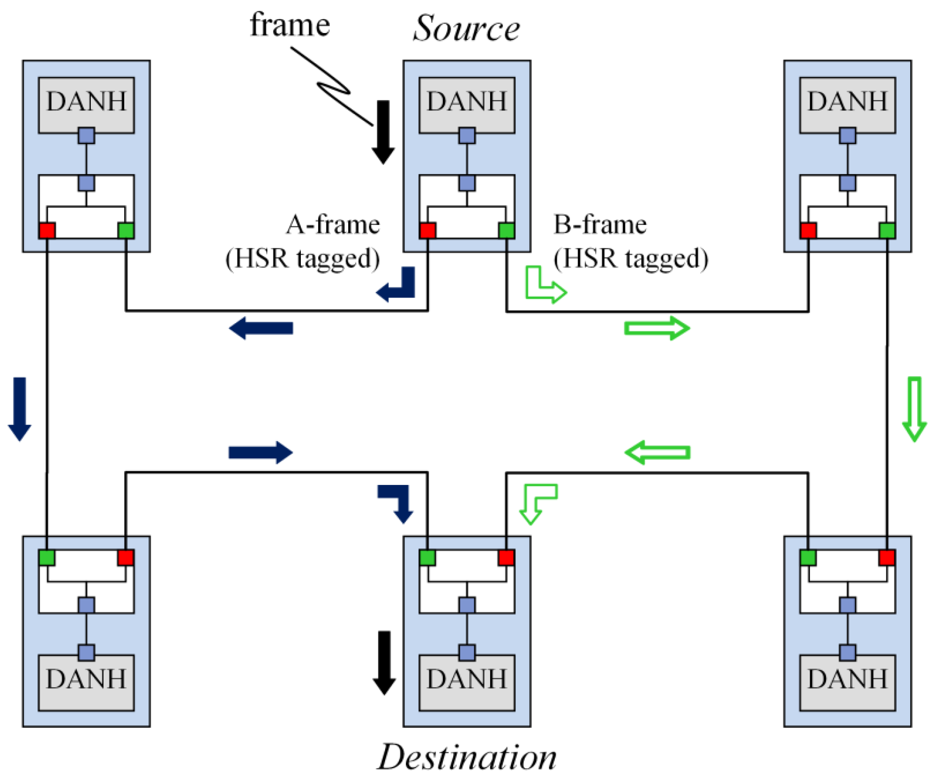
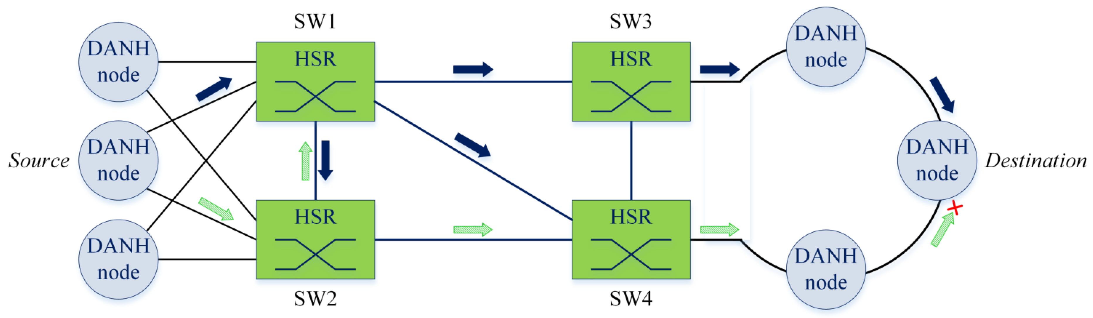
HSR was standardized by the International Electrotechnical Commission (IEC) as IEC62439-3 Clause 5 [8] and as one of the redundancy protocols selected for substation automation in the IEC61850 standard [
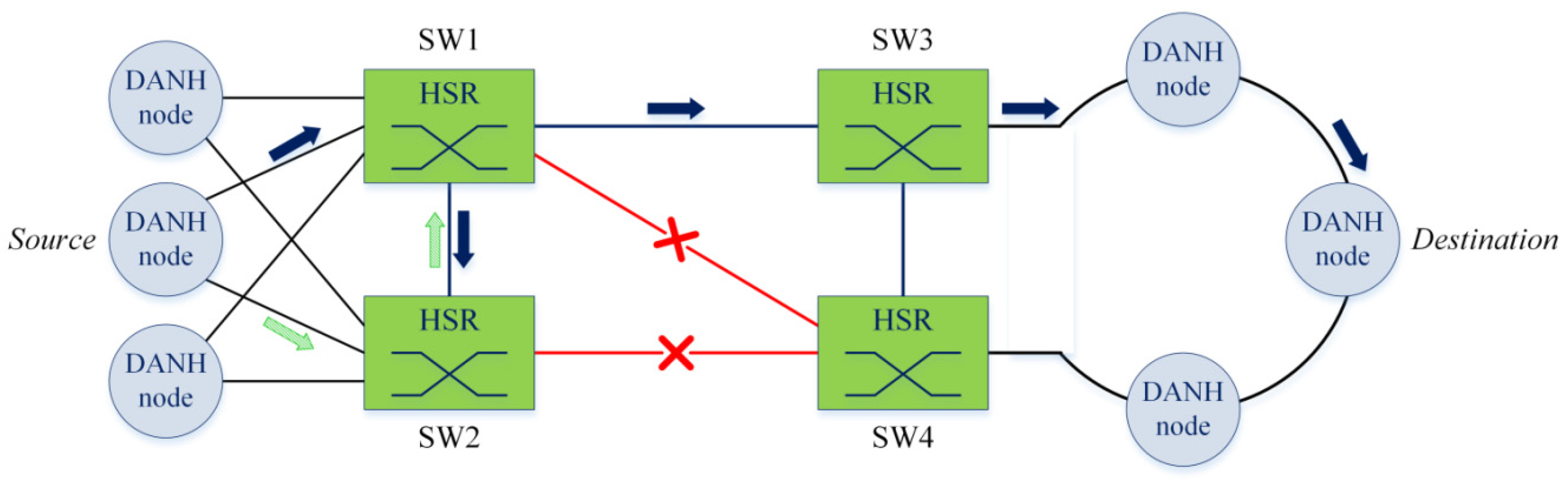
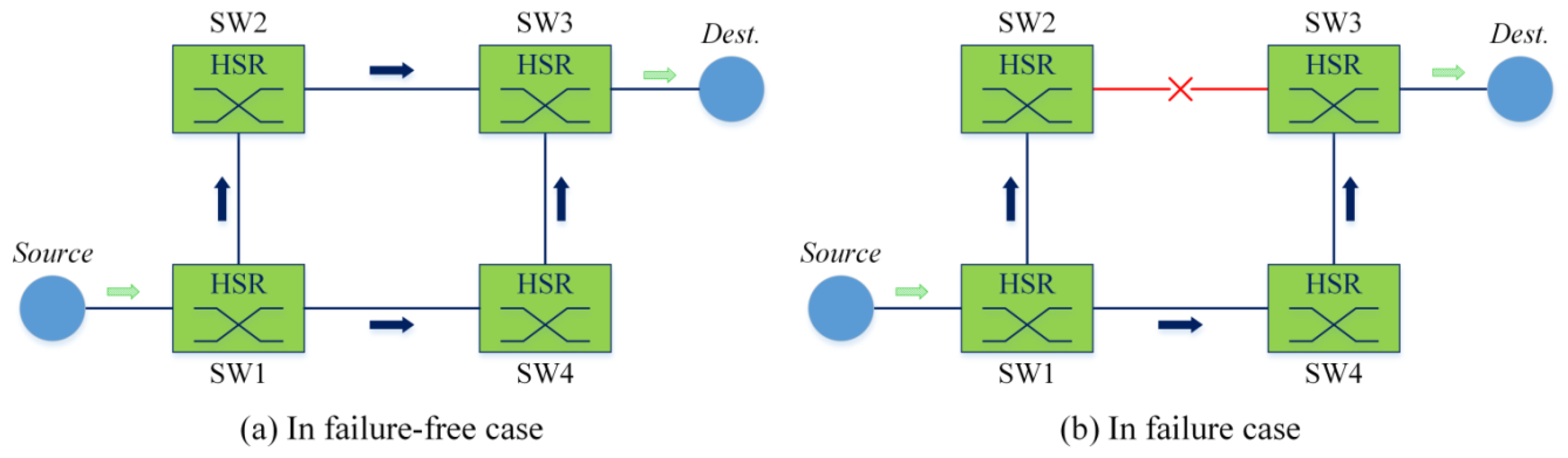
13]. HSR is a redundancy protocol for Ethernet that provides zero recovery time in a case of the failure of one component. HSR is based on the duplication of every frame sent in a ring topology. Each copy of the frame is injected in a different direction of the ring. In the fault-free state of the network, the destination node receives two identical frames, passes the first frame to its upper layers and discards the duplicate. In the case of failure of one component, such as link failure or node failure, only one frame is lost. The application on the destination node operates with the remaining frame undisturbed. Therefore, even in the case of a node or link failure, there is no communication interruption in the network. This feature of the HSR protocol makes it very useful for time-critical and mission-critical applications such as substation automation systems and automation networks. The HSR principles are described and discussed in [8,12,13,14].
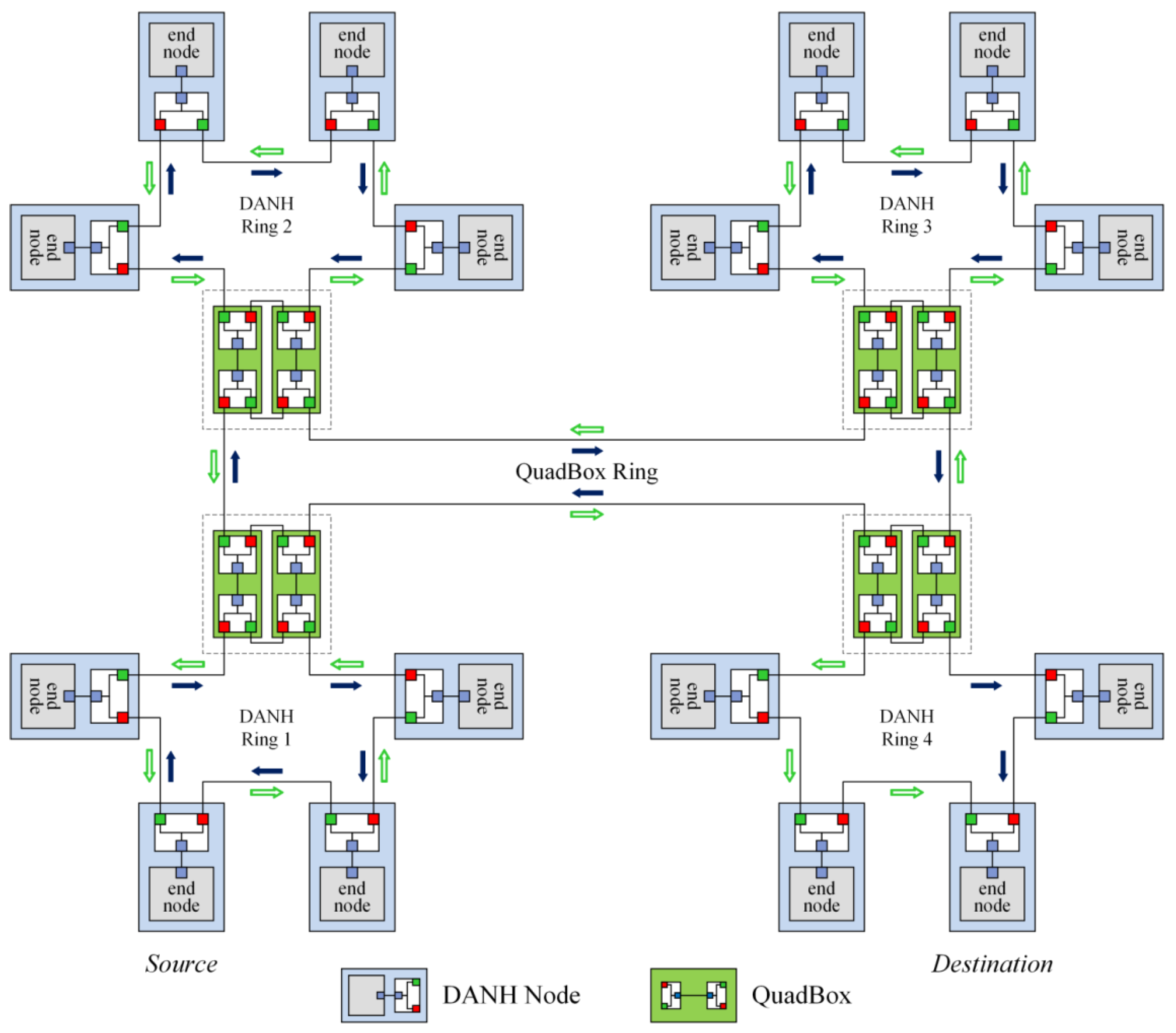
However, HSR is mainly used in ring topologies including single-ring and connected-ring networks. Standard HSR also generates excessively unnecessary redundant traffic frames in HSR networks. This drawback degrades network performance and may cause congestion and delay. Several approaches have been proposed to reduce the unnecessary traffic in HSR networks. Nsaif and Rhee [15] proposed an approach called quick removing (QR) to prevent the unnecessary traffic from circulating in the rings of HSR networks. Shin and Joe [16] proposed a traffic control (TC) method to remove duplicated and circulated frames from a ring by selecting one of nodes within the ring as the traffic control node. Abdulsalam and Rhee [17] proposed a method called port locking (PL) to filter unicast traffic for the DANH rings of HSR networks. Hong and Joe [18] introduced a packet transmission scheme with different periods based on a single-ring topology to reduce the HSR network-traffic load. Tien and Rhee [19] proposed a method of filtering HSR traffic (FHT) that filters unicast traffic not only for DANH rings but also for QuadBox rings. FHT also removes duplicated and circulated traffic in the rings. Ngo et al. [20] implemented the QR algorithm for HSR components to improve the availability of HSR. Tien, Nsaif and Rhee [21] proposed an optimal dual paths (ODP) approach that establishes optimal dual paths for each connection pair in an HSR network, based on the network’s topology. The dual paths are then used to forward unicast frames between each connection pair of nodes instead of duplicating and forwarding frames to all parts of the networks.
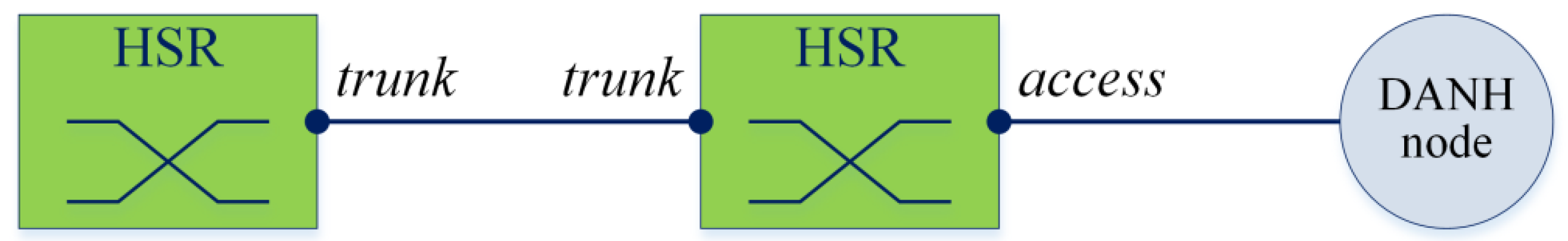
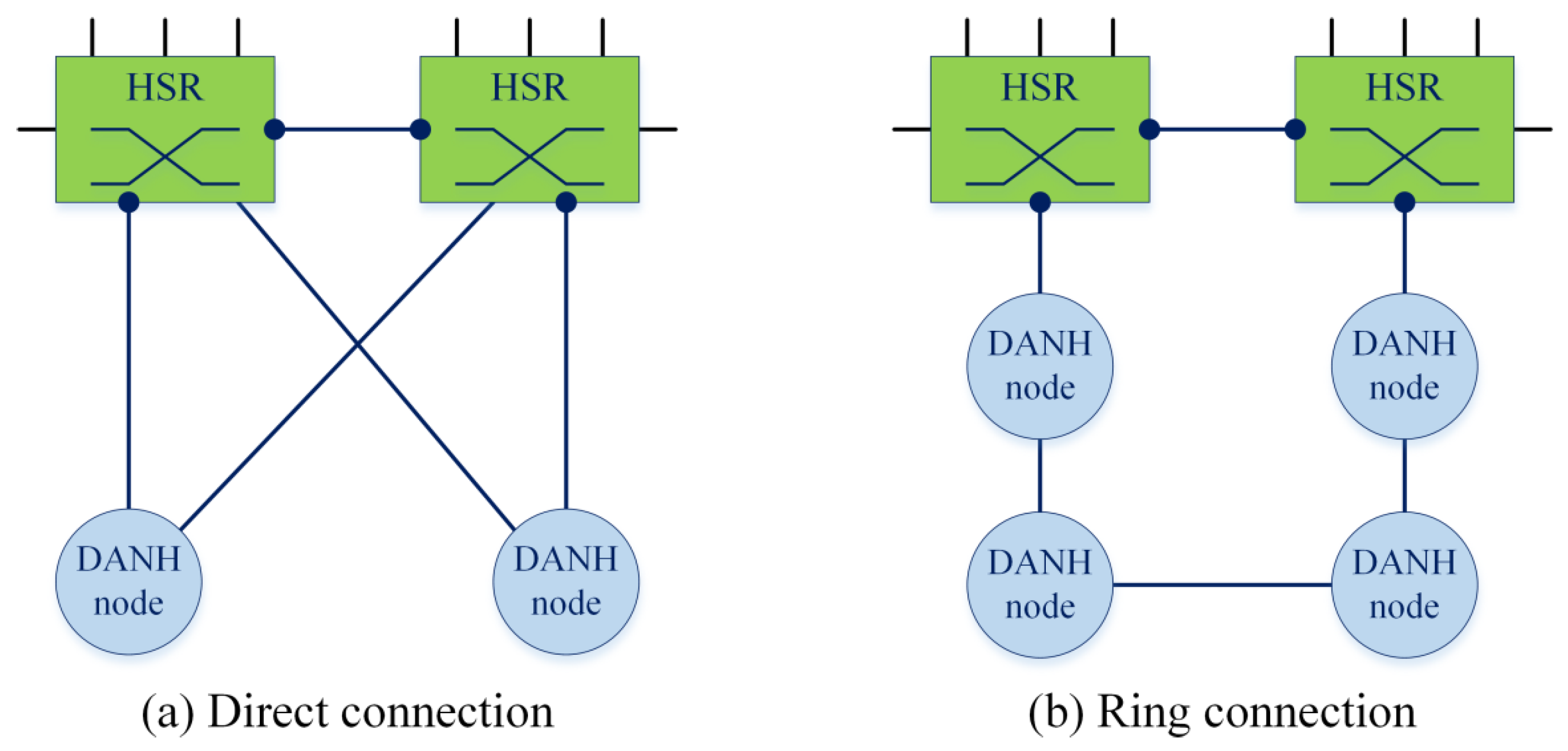
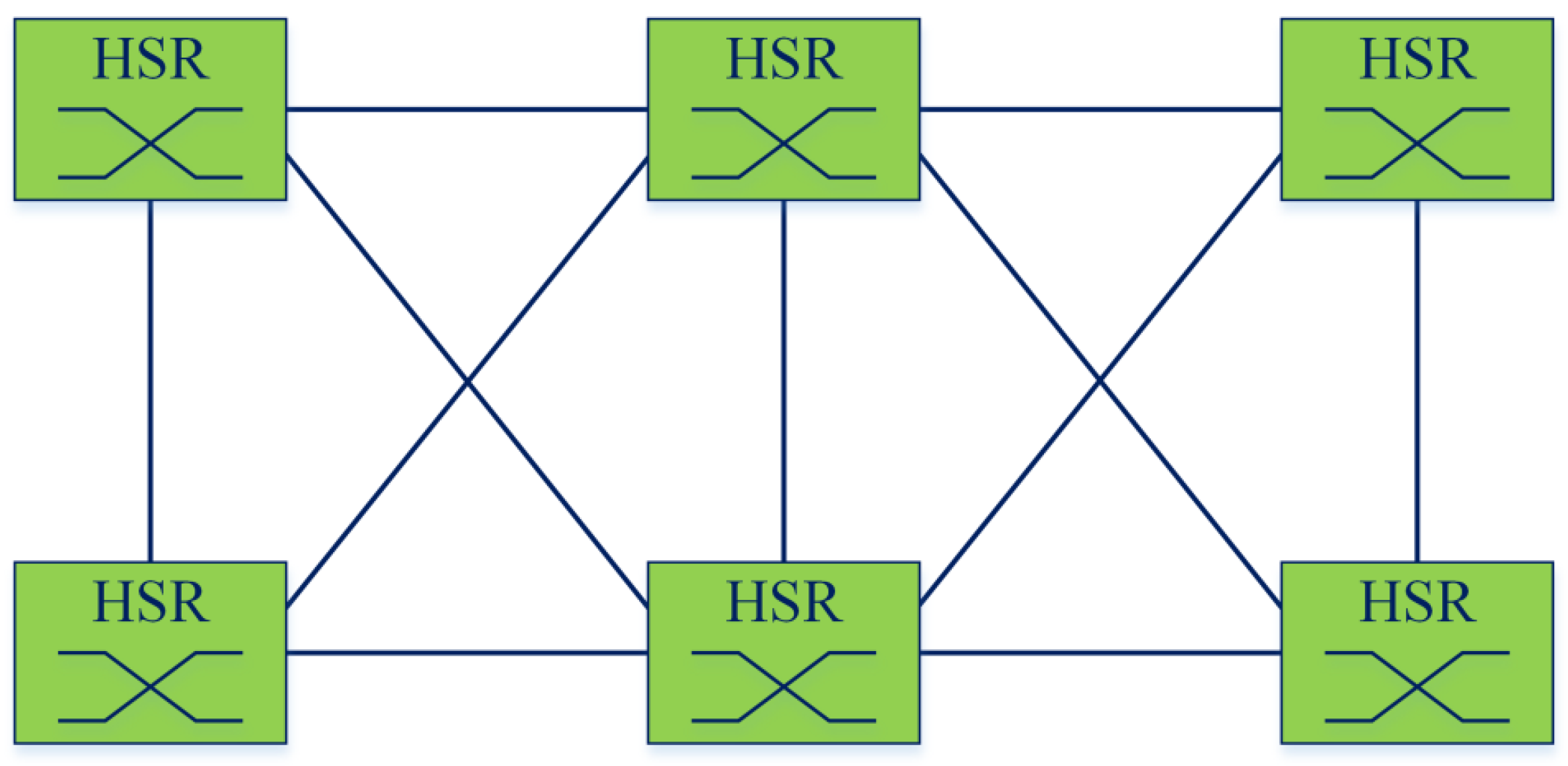
Unlike the mentioned approaches, which propose algorithms implemented in existing HSR components to improve the network traffic performance in HSR networks, in this paper, we develop a new HSR component, called the HSR switching node (SwitchBox), to apply HSR to any network topology as well as significantly reduce unnecessary redundant network traffic compared to the standard HSR. By using the new SwitchBox nodes, HSR can provide seamless redundancy for HSR networks in any topology and improve the network traffic performance in HSR networks.
The rest of this paper is organized as follows: in Section 2, we briefly introduce the standard HSR protocol and existing HSR nodes. Next, in Section 3, we describe the proposed SwitchBox component for HSR. In Section 4, the traffic performance of HSR with SwitchBox is analyzed, evaluated and compared to that of the standard HSR protocol. Section 5 describes several simulations and their results to evaluate and validate the performance analysis of HSR with SwitchBox. Finally, we provide our conclusions and suggestions for future work in Section 6.

2. Background

2.1. High-Availability Seamless Redundancy (HSR) Concepts

HSR follows the parallel redundancy protocol (PRP) principle of frame duplication over distinct paths [8]. But unlike PRP, which requires a duplicated network topology, HSR uses a single network.
The HSR protocol defines the following node types [8].
  • Doubly attached node for HSR (DANH): A DANH node is an HSR-capable switching end node that has two HSR ports sharing the same medium access control (MAC). These two ports form a single interface. The source DANH inserts the HSR tag into the frame received from upper layers, duplicates the frame into two frame copies and sends the two copies over both ports. The destination DANH receives two copies of the same frame, one from each port.
  • Redundancy Box (RedBox): Singly attached nodes (SAN), such as servers, maintenance laptops or printers cannot be directly connected to an HSR ring, since they have no HSR forwarding capability and do not support the HSR tag. A RedBox is used to connect SANs to the HSR ring. RedBoxes forward the frames over the ring like DANH nodes and act as proxies for all SANs that access them.
  • Quadruple port device (QuadBox): QuadBox nodes are used to connect HSR rings together. A QuadBox has four HSR ports that are divided into two pairs connected by an interlink; each pair shares the same MAC. QuadBoxes operate as HSR nodes toward both rings simultaneously. Although one QuadBox is sufficient to conduct the traffic in a fault-free network, two QuadBoxes are used to prevent a single point of failure [8].
HSR is mainly applied for ring topologies. The standard HSR protocol is used in single-ring and connected-ring networks.

2.1.1. Single-Ring Networks

In a single-ring HSR network, HSR uses the two HSR ports of each DANH node to interconnect all DANH nodes to the network, as shown in Figure 1. There is no QuadBox used in single-ring networks.
The source node sends two copies of the same frame simultaneously through each port in both directions in the ring. The two frame copies travel in opposite directions. If a DANH receives the frame but is neither its source nor its only destination, the DANH forwards the frame to its other port, except if it has already forwarded the same frame. The destination node of a unicast frame does not forward a frame for which it is the only destination. Frames forwarded in the ring carry the HSR tag inserted by the source node, which contains a sequence number. The doublet of the source MAC address and the sequence number uniquely identifies copies of the same frame. In the fault-free case of the network, the destination node receives two identical frames, passes the first frame to upper layers and discards the duplicate. If a single fault on the ring occurs, only one of the two frames travelling on the two network paths through the ring will experience a communication interruption. The second frame will still reach the destination node.
Figure 1. High-Availability Seamless Redundancy (HSR) example of single-ring topology for unicast traffic.
Energies 09 00036 g001

2.1.2. Connected-Ring Networks

To allow more complex network topologies, HSR rings can be connected through the use of QuadBoxes. A QuadBox forwards frames over each ring, passing the frames to another ring without changes. Figure 2 shows an example of a connected-ring network that consists of four pairs of QuadBoxes used to connect four DANH rings.
Figure 2. HSR example of the connected-ring topology for unicast traffic.
Energies 09 00036 g002

2.2. HSR Issues

(1)
Aside from ring topologies, the IEC 62439-3 briefly mentions other topologies to which the standard HSR can be applied. However, with current specifications and devices specified and defined in the current IEC 62439-3 standard [8], the standard HSR protocol is mainly used to provide seamless redundancy for ring-based topologies.
(2)
The second issue with respect to HSR is that it generates too much unnecessary redundant traffic in HSR networks. According to the forwarding rule of the standard HSR protocol, HSR nodes including DANH, RedBox and QuadBox nodes forward unicast frames from one port to other ports, unless they have already sent the same frame in that direction. The forwarding rule creates network traffic frames that circulate and double in HSR rings, as shown in Figure 2. The issue degrades the network performance and may cause network congestion and delay.
In this paper, we propose a new HSR switching component, called SwitchBox, which solves the above HSR issues. By using the SwitchBoxes in HSR networks, redundant traffic frames are significantly reduced and thus the traffic performance is improved. Additionally, HSR with SwitchBoxes can be applied for any network topology, such as ring topology, mesh topology or star topology. In this paper, the term “SwitchBox-based HSR” refers to HSR with SwitchBoxes.

3. The Proposed SwitchBox

3.1. SwitchBox Concepts

3.1.1. Definition

A SwitchBox is the switching node with many ports that performs the switching functionality in HSR networks. The symbol for the HSR SwitchBox is shown in Figure 3.
Figure 3. The symbol for the HSR SwitchBox.
Energies 09 00036 g003
The SwitchBox performs the following functions.
  • Learning MAC addresses of HSR terminal nodes including DANH nodes and RedBox nodes that connect to the HSR SwitchBox directly or in a ring. Unlike the standard Ethernet switches that learn the MAC addresses of all Ethernet nodes, the HSR SwitchBox learns the MAC addresses of only HSR terminal nodes that connect to the SwitchBox.
  • Building a MAC table that contains the MAC addresses of HSR terminal nodes that connect to the SwitchBox.
  • Forwarding HSR frames based on the MAC table.
  • Discarding duplicated HSR frames.

3.1.2. Port Types

There are two types of port defined for HSR SwitchBoxes: access and trunk port types. By default, HSR SwitchBoxes’ ports are set as access ports.
  • Access port: An access port is a port of an HSR SwitchBox that is connected to an HSR terminal node such as a DANH or a RedBox node.
  • Trunk port: A trunk port is a port of an HSR SwitchBox that is connected to another SwitchBox.
Figure 4 shows the port types of HSR SwitchBoxes. The port types can be automatically negotiated by using a control message (Hello message) or can be manually configured by network administrators.
Figure 4. Port types of HSR SwitchBoxes.
Energies 09 00036 g004

3.1.3. Connections to HSR Terminal Nodes

Standard HSR defines two types of HSR terminal nodes including DANH and RedBox nodes. The HSR terminal nodes can connect to HSR SwitchBoxes directly, as shown in Figure 5a, or in a DANH ring, as shown in Figure 5b. For convenience, in this paper, the term “DANH nodes” refers to HSR terminal nodes.
Figure 5. Types of connections between SwitchBoxes and HSR terminal nodes.
Energies 09 00036 g005

3.1.4. Forwarding Rule

The forwarding rule of the standard HSR protocol allows HSR nodes including DANH, RedBox and QuadBox nodes to forward traffic frames from one port to other ports unless they have already sent the same frame in that direction [8]. This forwarding rule creates network traffic that is duplicated and circulated in all HSR rings except the destination ring, as shown in Figure 6a. This issue results in too much unnecessary redundant traffic in HSR networks.
Figure 6. Forwarding a frame from node S to node D.
Energies 09 00036 g006
Instead of duplicating and circulating network traffic in HSR networks as current HSR components, SwitchBox forwards network unicast frames based on the MAC table.
SwitchBoxes forward and filter unicast frames in HSR networks based on the following rules:
  • Do not forward unicast frames to DANH rings that do not contain the destination of the frame.
  • Forward unicast frames on all trunk links that are used to connect SwitchBoxes.
  • Prevent traffic frames from doubling and circulating in rings.
When a SwitchBox receives a unicast frame, it looks up its MAC table to find an entry that matches the destination of the frame. If there is a matched entry, the frame is sent over the corresponding output port. Otherwise, the SwitchBox floods the frame to all its trunk ports except the one that received the frame. Additionally, the SwitchBox applies QR algorithm [15] for forwarding multicast/broadcast frames. By applying QR, when a SwitchBox receives a multicast/broadcast frame, it checks whether the frame has previously been received and forwarded. If not, it floods the frame. If so, it discards the frame. These forwarding rules allow SwitchBox-based HSR to prune redundant traffic frames and remove doubled and circulated traffic frames in HSR networks. Figure 6b shows an example of forwarding traffic frames under SwitchBox-based HSR. Intuitively, SwitchBox-based HSR significantly reduces redundant traffic frames compared with standard HSR.

3.2. Topologies

By using SwitchBoxes to connect terminal nodes in HSR networks, HSR can be applied to any topology, such as ring topology, mesh topology or star topology. Figure 7, Figure 8 and Figure 9 show SwitchBoxes-based HSR networks in ring, mesh, and star topologies, respectively.

3.2.1. Ring Topology

Figure 7. SwitchBox-based HSR in ring topology.
Energies 09 00036 g007

3.2.2. Mesh Topology

Figure 8. SwitchBox-based HSR in mesh topology.
Energies 09 00036 g008

3.2.3. Star Topology

Figure 9. SwitchBox-based HSR in star topology.
Energies 09 00036 g009

3.3. Operations

To provide seamless redundancy, HSR SwitchBoxes first discover and set port types to their ports. They then learn MAC addresses and build a MAC table that contains MAC addresses of HSR terminal nodes, including DANH nodes and RedBox nodes that connect to them. Finally, the SwitchBoxes make forwarding decisions based on the MAC table, and they discard duplicated frames.

3.3.1. Setting Switch Port Type

By default, ports of SwitchBoxes are set to the access type. The port types can be automatically negotiated by using Hello messages or can be manually configured by network administrators.
When an interface of a SwitchBox comes up, it sends a Hello message over the interface. When a SwitchBox receives a Hello message on a port, it sets the received port to the trunk type.
The process of setting port types for SwitchBoxes is shown in Figure 10.
Figure 10. The process of setting port types for SwitchBoxes.
Energies 09 00036 g010

3.3.2. Learning Medium Access Control (MAC) Address

In HSR networks, each DANH node periodically sends an HSR_Supervision frame over both its ports at every LifeCheckInterval (2000 ms by default) [8]. Each SwitchBox learns the MAC addresses of the DANH nodes that connect to it, based on receiving the HSR_Supervision frames sent by the DANH nodes.

3.3.3. Building MAC Table

SwitchBoxes forward HSR frames based on looking up the MAC table. Each SwitchBox builds its MAC table, which contains MAC addresses of the DANH nodes that connect to the SwitchBox. Each SwitchBox learns the DANH nodes’ MAC addresses based on HSR_Supervision frames sent by the DANH nodes.
When a SwitchBox receives an HSR_Supervision frame sent by a DANH node, it checks whether its MAC table contains the source MAC address of this frame. If not, the SwitchBox adds the source MAC address into its MAC table. If so, it updates the corresponding entry of the source MAC address. Each entry of the MAC table consists of the MAC address of a DANH node and the corresponding output port. By learning the MAC addresses of DANH nodes, each SwitchBox builds its MAC table containing MAC addresses of all DANH nodes connecting to it. When receiving an HSR frame, the SwitchBox makes forwarding decisions based on looking up the MAC table.
To keep the MAC table correct and updated, if a SwitchBox does not receive an HSR_Supervision frame from a DANH node within three LifeCheckIntervals, it will remove the entry of the DANH node from its MAC table.

3.3.4. Forwarding Frames

Multicast and Broadcast Frames

The SwitchBox applies QR algorithm [15] to forward multicast/broadcast frames in HSR networks. Based on the QR algorithm, when a SwitchBox receives a multicast or broadcast frame for the first time, it floods the frame to all its ports except the port on which the frame was received. If the SwitchBox receives any duplicates of the same frame, it discards the duplicates. The process of flooding multicast/broadcast frames by the SwitchBox is shown in Figure 11.
Figure 11. The process of forwarding multicast/broadcast frames at SwitchBoxes.
Energies 09 00036 g011

Unicast Frames

The SwitchBoxes make forwarding decisions for unicast frames based on the MAC table. When a SwitchBox receives an HSR unicast frame for the first time, it looks up its MAC table to find an entry that matches the destination MAC address of the frame. If it finds a matched entry, it then forwards the frame to the output port of the matched entry. Otherwise, it sends the frame over all its trunk ports, except the port on which the frame was received. The SwitchBox discards duplicates of the frame. The process of forwarding unicast frames at Switchboxes is shown in Figure 12.
The process of forwarding a traffic frame from a source DANH node to a destination DANH node under SwitchBox-based HSR in an HSR network is shown in Figure 13. The source node duplicates the HSR frame into two copies and sends the copies over its ports into the network. In the failure-free state, SwitchBoxes SW1 and SW2 look up their MAC table and forward the frame to their trunk ports connecting to other Switchboxes, since their MAC table does not contain the destination MAC address of the frame. When receiving the frame, SwitchBoxes SW3 and SW4 look up their MAC table and find that their MAC table has an entry that matches the destination MAC address of the frame; they then forward the frame to the corresponding output port instead of flooding the frame. DANH nodes in the destination DANH ring forward the frame from one port to the other port, except the destination DANH node. The destination DANH node receives two identical frames, passes the first frame to its upper layers, and discards the duplicate. All SwitchBoxes forward the frame when they have received it for the first time, and they discard duplicates of the frame.
Figure 12. The process of forwarding unicast frames at SwitchBoxes.
Energies 09 00036 g012
Figure 13. Forwarding a unicast frame in the failure-free case.
Energies 09 00036 g013
If a network failure occurs in the network, for example, a link failure between two SwitchBoxes SW2 and SW4, two frame copies still reach the destination node, as shown in Figure 14. Therefore, there is no communication interruption in the network in the case of a network failure.
Even if link failures occur on links SW2-SW4 and SW1-SW4, only one frame is lost, and the other frame still reaches the destination node through SW1 and SW3, as shown in Figure 15.
Figure 14. Forwarding a unicast frame in the case of a link failure.
Energies 09 00036 g014
Figure 15. Forwarding a unicast frame in the case of two link failures.
Energies 09 00036 g015

4. Performance Analysis

4.1. Redundancy Performance

Like RSTP, SwitchBox-based HSR provides redundancy in the network and can be applied to any network topology, such as ring topology, mesh topology or star topology. However, unlike RSTP, which suffers switchover delay in cases of failure, SwitchBox-based HSR provides seamless redundancy and zero switchover time in cases of failure.

4.1.1. Redundancy Performance under Rapid Spanning Tree Protocol (RSTP)

We consider a network with four Ethernet switches running RSTP, as shown in Figure 16.
Figure 16. Redundancy provided by RSTP.
Energies 09 00036 g016
In a failure-free case, RSTP blocks the redundant link between Ethernet SW1 and SW4 to avoid the switching loop, as shown in Figure 16a. The source node connecting to SW1 sends traffic frames to the destination node connecting to SW3 through the path, SW1-SW2-SW3. When the link between SW2 and SW3 fails, RSTP activates corresponding blocked ports in SW1 and SW4 to enable the blocked link between them, as shown in Figure 16b. Therefore, RSTP suffers switchover delay in a case of network failure.

4.1.2. Redundancy Performance under SwitchBox-Based HSR

We consider an HSR network with four HSR SwitchBoxes, as shown in Figure 17. In a failure-free case, when receiving unicast frames sent by a source node, SwitchBox SW1 looks up its MAC table and sends them over its trunk ports connecting to SwitchBoxes SW2 and SW4. SW2 and SW4 look up their MAC table and send the frames over another trunk port when they receive them for the first time. SwitchBox SW3 receives two copies of each frame from two links connected to it, looks up its MAC table and then forwards the first copy to the destination node and discards the duplicate. The process of forwarding the unicast frames in a failure-free case is shown in Figure 17a.
When the link between SwitchBoxes SW2 and SW3 fails, only one copy of each frame is lost, while the other copy still reaches the destination SwitchBox SW3 without a switchover delay, as shown in Figure 17b. SwitchBox SW3 looks up its MAC table and forwards the copy to the destination node. Therefore, SwitchBox-based HSR provides seamless redundancy with zero switchover time in case of network failure.
Figure 17. Redundancy provided by SwitchBox-based HSR.
Energies 09 00036 g017

4.2. Traffic Performance

This section describes the traffic performance analysis of SwitchBox-based HSR compared to the standard HSR. Since the standard HSR is mainly applied in ring topologies, we consider a sample network in the ring topology to analyze, evaluate and compare with respect to traffic performance.
To analyze and evaluate traffic performance, network traffic was chosen as a performance metric. Network traffic is defined as the total number of frame copies that travel on links and that are received by nodes in the network.
  • Network unicast traffic: Network unicast traffic is the total number of unicast frame copies that are delivered on links and received by nodes when a source node sends unicast frames to a destination node in the network.
  • Network broadcast traffic: Network broadcast traffic is the total number of broadcast frame copies that are delivered on links and received by nodes when a source node sends broadcast frames to the other nodes in the network.
We consider a sample network consisting of eight DANH rings; each DANH ring includes four DANH nodes, as shown in Figure 18.
QuadBoxes are used to connect DANH rings under the standard HSR, whereas SwitchBoxes are used to connect DANH rings under SwitchBox-based HSR. To avoid single points of failure in the network, two QuadBoxes/SwitchBoxes are used to connect to two rings.
Figure 18. A sample HSR network.
Energies 09 00036 g018

4.2.1. Notations

In this paper, we use some parameters for network traffic performance analysis. These parameters are denoted and described in Table 1.
Table 1. Parameters for network traffic performance analysis.
ParameterDescription
n t H S R 1 Network traffic when a source node sends a frame under standard HSR
n t S B 1 Network traffic when a source node sends a frame under SwitchBox-based HSR
n t H S R Network traffic when a source node sends N frames under standard HSR
n t S B Network traffic when a source node sends N frames under SwitchBox-based HSR
N R A set of all rings in the network
D R A set of all DANH rings
D R D A set of all DANH rings except the destination DANH ring
Q R A set of all QuadBox rings
S R A set of all SwitchBox rings
n S Total number of links in the source DANH ring
n D Total number of links in the destination DANH ring
n i Total number of links in the ith ring
N Total number of sent frames

4.2.2. Under Standard HSR Protocol

Unicast Traffic

When a source node sends a unicast frame to a destination node, standard HSR protocol forwards and circulates the frame in all rings, except the destination DANH ring; two copies of the frame are delivered on each link, one in each direction. The destination DANH ring does not circulate and duplicate the frame, since the destination node does not forward the frame. Figure 19 shows the process of forwarding a unicast frame in the sample network under standard HSR protocol.
Clearly, if a frame is circulated and doubled in a ring, the number of copies of the frame delivered in the ring is equal to twice the total number of links in the ring. Otherwise, the number of frame copies is equal to the total number of links in the ring.
Figure 19. Network unicast traffic under standard HSR protocol.
Energies 09 00036 g019
Network unicast traffic when the source node sends a unicast frame to the destination node under standard HSR protocol, denoted by n t H S R 1 , is calculated as follows:
n t H S R 1 = n D + i D R D 2 n i + i Q R 2 n i
where n D is the number of links in the destination ring, n i is the number of links in the i-th ring, D R D is a set of all DANH rings except the destination DANH ring, and QR is a set of all QuadBox rings:
i D R D 2 n i = i D R 2 n i 2 n D
i D R 2 n i + i Q R 2 n i = i N R 2 n i
where D R is a set of all DANH rings and N R is a set of all rings in the network.
Equation (1) can be rewritten as follows:
n t H S R 1 = i N R 2 n i n D
The following equation can be used to determine network unicast traffic under standard HSR protocol, denoted by n t H S R , when a source node sends N unicast frames to a destination node:
n t H S R = N ( i N R 2 n i n D )
For the sample network in Figure 18, the number of links of each QuadBox ring is equal to 8, whereas the number of links of each DANH ring is equal to 6. Network unicast traffic is calculated as:
n t H S R = N ( i = 1 8 2 × 6 + i = 1 3 2 × 8 ) 6 = 138 N   ( f r a m e s )

Multicast/Broadcast Traffic

When a source node sends a broadcast frame to the network, standard HSR protocol forwards and circulates the frame in all rings of the network. Figure 20 shows the process of forwarding a multicast/broadcast frame in the sample network under standard HSR protocol.
Figure 20. Network multicast/broadcast traffic under standard HSR protocol.
Energies 09 00036 g020
Network broadcast traffic when the source node sends a broadcast frame under standard HSR protocol, denoted by n t H S R 1 , is calculated as follows:
n t H S R 1 = i N R 2 n i = i D R 2 n i + i Q R 2 n i
The following equation can be used to determine network broadcast traffic under standard HSR protocol, denoted by n t H S R , when a source node sends N broadcast frames:
n t H S R = 2 N i N R n i
For the sample network in Figure 18, network broadcast traffic n t H S R is calculated as follows:
n t H S R = 2 N ( i = 1 8 6 + i = 1 3 8 ) = 144   ( f r a m e s )

4.2.3. Under SwitchBox-Based HSR

Unicast Traffic

When the source node sends unicast frames to the destination node, SwitchBox-based HSR filters the unicast traffic for DANH rings that do not contain the destination of the frame, as shown in Figure 21. In that case, SwitchBoxes connecting to DANH rings 1, 2, 3, 4, 6, 7 and 8 do not forward the unicast frames to the DANH rings, since their MAC table does not contain the destination MAC address of the frames. Only the SwitchBox that connects to DANH ring 5 forwards the unicast frames to DANH ring 5, which contains the destination.
Figure 21. Network unicast traffic under SwitchBox-based HSR.
Energies 09 00036 g021
Network unicast traffic under SwitchBox-based HSR when the source node sends a unicast frame to the destination node, denoted by n t S B 1 , is calculated as follows:
n t S B 1 = n S + n D + t f S R
where n S is the number of links in the source DANH ring, n D is the number of links in the destination DANH ring, and t f S R is the number of frame copies delivered in all SwitchBox rings:
t f S R = i S R n i 1
where SR is a set of all SwitchBox rings that are used to connect DANH rings. The network traffic t f S R that is forwarded in all SwitchBox rings is equal to ( i S R n i 1 ) because the unicast frame is not forwarded on the link between two SwitchBoxes of the destination DANH ring.
Equation (8) can be re-written as follows:
n t S B 1 = n S + n D + ( i S R n i 1 )
The generalized equation for calculating network unicast traffic under SwitchBox-based HSR when a source node sends N unicast frames to a destination node is as follows:
n t S B = N ( n s + n d + i S R n i 1 )
For the example network in Figure 18, the number of links of each SwitchBox ring is equal to 8, whereas the number of links of each DANH ring is equal to 5, excluding one link between two SwitchBoxes in the DANH ring. Network unicast traffic n t S B is calculated as follows:
n t S B = N ( 5 + 5 + i = 1 3 8 1 ) = 33 N   ( f r a m e s )
Clearly, for our sample network, SwitchBox-based HSR reduces network unicast traffic by about 76% compared with standard HSR.

Multicast/Broadcast Traffic

When the source node sends broadcast frames, all SwitchBoxes forward the frames to their corresponding DANH rings if they receive the frames for the first time, as shown in Figure 22. Otherwise, they discard the duplicates.
However, unlike standard HSR, which circulates the frames in all rings of the network, SwitchBox-based HSR does not circulate the broadcast frames by using QR [15]. By using QR to send broadcast frames, the number of broadcast frame copies that are delivered in a ring is equal to (n + 1), where n is the number of links in the ring.
Figure 22. Network broadcast traffic under SwitchBox-based HSR.
Energies 09 00036 g022
Network broadcast traffic under SwitchBox-based HSR when the source node sends a broadcast frame is calculated as follows:
n t S B 1 = i N R ( n i + 1 ) = i D R ( n i + 1 ) + i S R ( n i + 1 )
The generalized equation for calculating network broadcast traffic under SwitchBox-based HSR when a source node sends N broadcast frames can be calculated as follows:
n t S B = N ( i D R ( n i + 1 ) + i S R ( n i + 1 ) )
For the sample network in Figure 18, network traffic n t S B is calculated as follows:
n t S B 1 = N ( i = 1 8 6 + i = 1 3 9 ) = 75 N   ( f r a m e s )
Clearly, for our sample network, SwitchBox-based HSR reduces network broadcast traffic by 48% compared with standard HSR.

5. Simulations

To validate the analyzed traffic performance and evaluate network traffic performance of the proposed SwitchBox, various simulations were carried out using the OMNeT++ simulation tool [22].

5.1. Simulation Description

The two following simulations were conducted to evaluate and validate the proposed SwitchBox.
  • Simulation 1: Validate seamless redundancy. This simulation was performed to validate the seamless redundancy provided by the SwitchBox-based HSR.
  • Simulation 2: Validate the analyzed traffic performance. This simulation was conducted to validate the analyzed traffic performance described in Section 4.
  • Simulation 3: Evaluate and compare traffic performance. This simulation was conducted to evaluate and compare the traffic performance of the SwitchBox-based HSR with that of the standard HSR.

5.1.1. Simulation 1: Validate Seamless Redundancy

In this simulation, we considered an HSR network with six SwitchBoxes, as shown in Figure 23. A source node sent unicast frames to a destination node. During the communications, we assumed that three link failures occurred on the following links: the link between SwitchBoxes SW1 and SW3, the link between SwitchBoxes SW2 and SW4, and the link between SwitchBoxes SW4 and SW6.
Figure 23. The network in Simulation 1.
Energies 09 00036 g023
In the simulation, the source node sent N unicast frames to the destination node (N = 10, 20, …, 100). The number of unicast frames received at the destination nodes was recorded to evaluate the redundancy performance of the SwitchBox-based HSR.

5.1.2. Simulation 2: Validate the Analyzed Traffic Performance

We considered the sample network in Figure 18. Simulations were conducted for both unicast and broadcast traffic described and analyzed in Section 4. In these simulations, the source node sent N traffic frames, including unicast and broadcast frames (N = 10, 20, …, 100). Network traffic under the standard HSR and the SwitchBox-based HSR was recorded for comparison with the analyzed network traffic described in Section 4.

5.1.3. Simulation 3: Evaluate and Compare the Traffic Performance

The objective of the simulation was to evaluate and compare the traffic performance of the SwitchBox-based HSR with that of the standard HSR. Simulations were conducted for both unicast and broadcast traffic. In these simulations, the source node sent N traffic frames, including unicast and broadcast frames (N = 10, 20, …, 100). Network traffic under the standard HSR and the SwitchBox-based HSR was recorded for evaluation and comparison.

Case 1

We considered a sample HSR network consisting of twelve DANH rings; each DANH ring included ten DANH nodes, as shown in Figure 24.
Figure 24. The sample HSR network in case 1 of Simulation 3.
Energies 09 00036 g024

Case 2

In that case, we considered a sample HSR network in Figure 25 consisting of twenty DANH rings that are connecting through a QuadBox/SwitchBox ring. Each DANH ring included ten DANH nodes.
Figure 25. The sample HSR network in case 2 of Simulation 3.
Energies 09 00036 g025

5.2. Simulation Results

5.2.1. Simulation 1

Table 2 shows the network frame statistics in Simulation 1. The simulation results show that there is no lost frame during the communications. In other words, the SwitchBox-based HSR provides seamless redundancy with zero switchover time in a case of failure.
Table 2. Network frame statistics in Simulation 1.
Number of Sent FramesNumber of Received FramesNumber of Lost Frames
10100
20200
30300
40400
50500
60600
70700
80800
90900
1001000

5.2.2. Simulation 2

Table 3 shows the network traffic frames recorded from the simulation for both unicast and broadcast traffic under the standard HSR protocol and the SwitchBox-based HSR.
Table 3. Network traffic frames in Simulation 2.
Number of Sent FramesUnicast TrafficBroadcast Traffic
Standard HSRSwitchBox-Based HSRStandard HSRSwitchBox-Based HSR
10357061036801850
207140122073603700
3010,710183011,0405550
4014,280244014,7207400
5017,850305018,4009250
6021,420366022,08011,100
7024,990427025,76012,950
8028,560488029,44014,800
9032,130549033,12016,650
10035,700610036,80018,500
Figure 26a shows the comparison of the analytical unicast traffic performance and Figure 26b shows the comparison of the simulated unicast traffic performance for the SwitchBox-based HSR with the standard HSR. The analytical and simulation results are the same. In this case, the analytical and simulation results show that the SwitchBox-based HSR reduces network unicast traffic by 76% compared with the standard HSR.
Figure 27a shows the comparison of the analytical broadcast traffic performance and Figure 27b shows the comparison of the simulated broadcast traffic performance for the SwitchBox-based HSR compared with the standard HSR. The simulation results are similar to the analytical results. In this case, the analytical and simulation results show that the SwitchBox-based HSR reduces network broadcast traffic by up to 49% compared with the standard HSR.
Figure 26. Comparison of the analytical and simulated unicast traffic performance. (a) Analytical unicast traffic; (b) Simulated unicast traffic.
Energies 09 00036 g026
Figure 27. Comparison of the analytical and simulated broadcast traffic performance. (a) Analytical broadcast traffic; (b) Simulated broadcast traffic.
Energies 09 00036 g027

5.2.3. Simulation 3

Table 4 shows network traffic frames recorded in case 1 of the simulation for both unicast and broadcast traffic under the standard HSR protocol and the SwitchBox-based HSR.
Table 4. Network traffic frames in case 1 of Simulation 3.
Number of Sent FramesUnicast TrafficBroadcast Traffic
Standard HSRSwitchBox-Based HSRStandard HSRSwitchBox-Based HSR
10357061036801850
207140122073603700
3010,710183011,0405550
4014,280244014,7207400
5017,850305018,4009250
6021,420366022,08011,100
7024,990427025,76012,950
8028,560488029,44014,800
9032,130549033,12016,650
10035,700610036,80018,500
Table 5 shows the network traffic frames recorded in case 2 of the simulation for both unicast and broadcast traffic under the standard HSR protocol and the SwitchBox-based HSR.
Table 5. Network traffic frames in case 2 of Simulation 3.
Number of Sent FramesUnicast TrafficBroadcast Traffic
Standard HSRSwitchBox-Based HSRStandard HSRSwitchBox-Based HSR
10549061056002810
2010,980122011,2005620
3016,470183016,8008430
4021,960244022,40011,240
5027,450305028,00014,050
6032,940366033,60016,860
7038,430427039,20019,670
8043,920488044,80022,480
9049,410549050,40025,290
10054,900610056,00028,100
Figure 28 shows the comparison of the unicast and broadcast traffic performance for the SwitchBox-based HSR compared to the standard HSR. In this case, the simulation results show that the SwitchBox-based HSR reduced network unicast traffic by 83% and network broadcast traffic by 50% compared to the standard HSR.
Figure 28. Comparison of the network traffic performance between the standard HSR and the SwitchBox-based HSR in case 1 of Simulation 3. (a) Unicast traffic; (b) Broadcast traffic.
Energies 09 00036 g028
Figure 29 shows the comparison of the unicast and broadcast traffic performance for the SwitchBox-based HSR compared to the standard HSR. In this case, the simulation results show that the SwitchBox-based HSR reduced network unicast traffic by 89% and network broadcast traffic by 50% compared to the standard HSR.
Figure 29. Comparison of the network traffic performance between the standard HSR and the SwitchBox-based HSR in case 2 of Simulation 3. (a) Unicast traffic; (b) Broadcast traffic.
Energies 09 00036 g029

5.3. Discussion

The results of Simulation 1 demonstrate that SwitchBox-based HSR provides seamless redundancy for HSR networks in any topology. Unlike RSTP, which suffers switchover delay, SwitchBox-based HSR provides zero recovery time in case of network failures.
The results of Simulation 2 validate the unicast and broadcast traffic performance analyzed in Section 4. The simulation results shows that the simulated traffic performance is similar to the analytical traffic performance.
The results of Simulation 3 demonstrate that network traffic performance of SwitchBox-based HSR is much better than that of the standard HSR. Unlike standard HSR, which duplicates and circulates unicast traffic frames in all rings, SwitchBox-based HSR does not forward the unicast traffic frames to DANH rings that do not contain the destination of the frames. In addition, SwitchBox-based HSR prevents traffic unicast/broadcast frames from circulating in rings. Therefore, SwitchBox-based HSR significantly reduces network traffic compared with the standard HSR. Numerically, in our sample networks, SwitchBox-based HSR reduces unicast network traffic by up to 89% for unicast traffic and by 50% for broadcast traffic compared with the standard HSR. Table 6 shows a comparison of SwitchBox-based HSR and existing redundancy protocols including RSTP, MRP, PRP and standard HSR.
Table 6. Comparison of redundancy protocols.
ProtocolStandardRedundancySeamless RedundancyTopology
RSTPIEEE 802.1D-2004 [3]NetworkNoAny topology
MPRIEC 62439-2 [4]NetworkNoRing
PRPIEC 62439-3 [8]End nodesYesDual networks
Standard HSRIEC 62439-3 [8]End nodesYesRing
SwitchBox-based HSR-Network and end nodesYesAny topology

6. Conclusions

In this paper, we have developed a new HSR switching node, called SwitchBox. By using SwitchBoxes, HSR can be applied to any network topology, such as ring, mesh or star topologies. SwitchBoxes forward unicast traffic frames based on the MAC table and filter unicast traffic frames for DANH rings that do not contain the destination of the frames. Additionally, SwitchBox-based HSR prevents networks from doubling and circulating unicast and broadcast traffic frames in HSR networks. Therefore, SwitchBox-based HSR significantly reduces network traffic compared with the standard HSR. The simulation results showed that, for our sample networks, SwitchBox-based HSR reduced network traffic by up to 89% for unicast traffic and by 50% for broadcast traffic compared with the standard HSR protocol, thus saving network bandwidth and improving network traffic performance for time-critical and mission-critical systems, such as substation automation systems, automation networks, and other industrial Ethernet networks. Our future work will develop and implement SwitchBox-based HSR in hardware devices.

Acknowledgments

This research was supported by the Technology Innovation Program (No. 10058109) funded by the Ministry of Trade, Industry & Energy (MI, Korea) and the Basic Science Research Program (No. NRF-2013R1A1A2008406) through the National Research Foundation of Korea (NRF) funded by the Ministry of Science, Information and Communications Technologies (ICT).

Author Contributions

Authors Nguyen Xuan Tien and Jong Myung Rhee conceived and developed the ideas behind the research. Nguyen Xuan Tien carried out the performance analysis and simulations, and wrote the paper under supervision of Jong Myung Rhee. Jong Myung Rhee supervised the research and finalized the paper.

Conflicts of Interest

The authors declare no conflict of interest.

References

  1. IEEE 802.3—IEEE Standards for Ethernet. Available online: http://www.ieee802.org/3/ (accessed on 30 June 2015).
  2. Decotignie, J.D. Ethernet-based real-time and industrial communications. IEEE Proc. 2004, 93, 1102–1117. [Google Scholar] [CrossRef]
  3. IEEE 802.1D-2004—IEEE Standard for Local and Metropolitan Area Networks: Media Access Control (MAC) Bridges. Available online: http://www.ieee802.org/1/pages/802.1D-2003.html (accessed on 30 June 2015).
  4. International Electrotechnical Commission (IEC). Industrial Communications Networks: High-Availability Automation Networks, Part 2: Media Redundancy Protocol (MRP); IEC 62439-2; The International Electrotechnical Commission: Geneva, Switzerland, 2010. [Google Scholar]
  5. Huynh, M.; Goose, S.; Mohapatra, P.; Liao, R. RRR: Rapid ring recovery submillisecond decentralized recovery for ethernet ring. IEEE Trans. Comput. 2011, 60, 1561–1570. [Google Scholar] [CrossRef]
  6. IEEE Time-Sensitive Networking Task Group. Available online: http://www.ieee802.org/1/pages/tsn.html (accessed on 30 November 2015).
  7. Kehrer, S.; Kleineberg, O.; Heffernan, D. A comparison of Fault-Tolerance Concepts for IEEE 802.1 Time Sensitive Networks (TSN). In Proceedings of the 2014 IEEE Emerging Technology and Factory Automation (ETFA), Barcelona, Spain, 16–19 September 2014; pp. 1–8.
  8. International Electrotechnical Commission (IEC). Industrial Communications Networks: High-Availability Automation Networks, Part 3: Parallel Redundancy Protocol (PRP) and High-Availability Seamless Redundancy (HSR); IEC 62439-3; The International Electrotechnical Commission: Geneva, Switzerland, 2012. [Google Scholar]
  9. Prytz, G. Network Recovery Time Measurements of RSTP in an Ethernet Ring Topology. In Proceedings of the 2007 IEEE Conference on Emerging Technologies and Factory Automation (ETFA2007), Patras, Greece, 25–28 September 2007; pp. 1247–1253.
  10. Giorgetti, A.; Cugini, F.; Paolucci, F.; Valcarenghi, L.; Pistone, A.; Castoldi, P. Performance analysis of media redundancy protocol (MRP). IEEE Trans. Ind. Inform. 2013, 9, 218–227. [Google Scholar] [CrossRef]
  11. IEEE Audio and Video Bridging Task Group. Available online: http://www.ieee802.org/1/pages/avbridges.html (accessed on 30 November 2015).
  12. Kirrmann, H.; Weber, K.; Kleineberg, O.; Weibel, H. HSR: Zero recovery time and low-cost redundancy for Industrial Ethernet (High availability seamless redundancy, IEC 62439-3). In Proceedings of the 2009 IEEE Conference on Emerging Technologies & Factory Automation (ETFA2009), Mallorca, Spain, 22–25 September 2009; pp. 1–4.
  13. International Electrotechnical Commission (IEC). Network Engineering Guidelines for Communication Networks and Systems in Substations; IEC 61850-90-4; The International Electrotechnical Commission: Geneva, Switzerland, 2013. [Google Scholar]
  14. International Electrotechnical Commission (IEC). Industrial Communications Networks—High-Availability Automation Networks, Part 1: General Concepts and Calculation Methods; IEC 62439-1; The International Electrotechnical Commission: Geneva, Switzerland, 2010. [Google Scholar]
  15. Nsaif, S.A.; Rhee, J.M. Improvement of high-availability seamless redundancy HSR traffic performance for smart grid communications. J. Commun. Netw. 2012, 14, 653–661. [Google Scholar] [CrossRef]
  16. Shin, M.; Joe, I. Performance improvement for the HSR ring protocol with traffic control in smart grid. In Proceedings of the 2012 Future Generation Information Technology Conference (FGIT), Gangwon, Korea, 16–19 December 2012; pp. 48–55.
  17. Abdulsalam, I.R.; Rhee, J.M. Improvement of high-availability seamless redundancy (HSR) unicast traffic performance using port locking. In Proceedings of the Fourth World Congress on Software Engineering, Hong Kong, China, 3–4 December 2013.
  18. Hong, S.; Joe, I. A novel packet transmission scheme with different periods according to the HSR ring direction in smart grid. In Proceedings of the 2012 Future Generation Information Technology Conference (FGIT), Gangwon, Korea, 16–19 December 2012; pp. 95–102.
  19. Tien, N.X.; Rhee, J.M. FHT: A novel approach for filtering high-availability seamless redundancy (HSR) traffic. Energies 2015, 8, 6249–6274. [Google Scholar] [CrossRef]
  20. Ngo, H.D.; Yang, H.S.; Ham, D.W.; Rhee, J.M.; An, Y.H.; Han, J.R.; Lee, Y.J.; Lee, N.H. An improved High-availability Seamless Redundancy (HSR) for dependable Substation Automation System. In Proceedings of the 16th International Conference on Advanced Communication Technology (ICACT), Pyeongchang, Korea, 16–19 February 2014.
  21. Tien, N.X.; Nsaif, S.A.; Rhee, J.M. High-Availability Seamless Redundancy (HSR) traffic reduction using optimal dual paths (ODP). In Proceedings of the International Conference on Green and Human Information Technology (ICGHIT), DaNang, Vietnam, 4–6 February 2015.
  22. OMNeT++ Version 4.6 Simulator. Available online: http://www.omnetpp.org/ (accessed on 15 June 2015).

