Article

Comparison of Degradation on Aluminum Reflectors for Solar Collectors due to Outdoor Exposure and Accelerated Aging

by
Johannes Wette
1,*,
Florian Sutter
1,
Aránzazu Fernández-García
2,
Stefan Ziegler
3 and
Reinhard Dasbach
4
1
DLR German Aerospace Center, Institute of Solar Research, Plataforma Solar de Almería, Ctra. Senés Km. 4, Apartado 39, E04200 Tabernas, Almería, Spain
2
Centro de Investigaciones Energéticas, Medioambientales y Tecnológicas (CIEMAT), Plataforma Solar de Almería, Ctra. Senés Km. 4, P.O. Box 44, E04200 Tabernas, Almería, Spain
3
Alanod GmbH & Co. KG, Egerstr. 12, 58256 Ennepetal, Germany
4
Almeco GmbH, Claude Breda Straße 3, 06406 Bernburg, Germany
*
Author to whom correspondence should be addressed.
Energies 2016, 9(11), 916; https://doi.org/10.3390/en9110916
Submission received: 28 September 2016 / Revised: 31 October 2016 / Accepted: 1 November 2016 / Published: 5 November 2016
(This article belongs to the Special Issue Urban Generation of Renewable Energy and Sustainable Cities)

Abstract

:
Reflectors for concentrated solar thermal technologies need to withstand 20 or even 30 years of outdoor exposure without significant loss of solar specular reflectance. In order to test the durability of innovative reflectors within a shorter period of time, an accelerated aging methodology is required. The problem with accelerated testing is that poor correlation between laboratory and field test results has been achieved in the past. This is mainly because unrealistic degradation mechanisms are accelerated in the weathering chambers. In order to define a realistic testing procedure, a high number of accelerated aging tests have been performed on differently coated aluminum reflectors. The degradation mechanisms of the accelerated tests have been classified and systematically compared to samples that have been exposed at nine different exposure sites outdoors. Besides the standardized aging tests, innovative aging procedures have been developed in such way that the agreement to the degradation pattern observed outdoors is increased. Although degradation depends on materials and location, five generic degradation mechanisms were detected. Standardized tests only reproduced one or two of the five mechanisms detected outdoors. Additionally, several degradation effects that were not observed outdoors appeared. The innovative accelerated aging tests of artificially soiled samples were able to reproduce three of the five mechanisms observed outdoors, presenting a much more realistic overall degradation pattern.

Graphical Abstract

1. Introduction

Industry is one of the main consumers of energy worldwide, around 30% [1], with direct thermal energy (known as industrial process heat, IPH) representing a large share of this energy demand in many sectors [2]. As the temperature requirements of IPH applications range from 60 °C to 260 °C [3], concentrating solar thermal systems are becoming essential for covering such thermal energy demand with renewable energies [4]. These small-sized concentrating solar thermal systems (including small-sized parabolic-trough collectors, PTC, compound parabolic concentrators, CPC, and solar cookers) are also important for the thermal energy supply in sustainable cities, isolated locations and rural areas, covering applications such as for solar cooking [5,6], domestic hot water, space heating, pumping irrigation water, desalination and water treatment [7]. In addition, concentrating solar thermal technologies for power production (typically named Concentrated Solar Power, CSP) currently represent the most promising solution to supply a significant share in the renewable energy mix [8,9]. Consequently, concentrating solar thermal systems are contributing to mitigate the impact of energy production in the global warming, to achieve a significant share of renewable energy and to build more sustainable cities.
The aging and degradation study of components for concentrating solar thermal technologies are a crucial factor for their deployment [10,11]. Meeting and assuring of lifetime goals for the components is important for the success of this renewable energy technology and for its competitiveness with other energy production technologies, especially with conventional ones. The reflectors are a key component that concentrate the sunlight and direct it to the receiver. Lifetime goals for reflector materials range up to 20 or even 30 years as demanded by the industry [12].
Nowadays, the widest used type of reflector is a silvered glass mirror [13]. The silver layer is applied to a 4 mm glass substrate. The silver is protected on the back side by a copper layer and a system of typically three protective paint coatings. Two main alternative types of mirrors are discussed for use in CSP plants: silvered polymer foils and aluminum mirrors. This paper focuses on aluminum mirrors, which consist of an aluminum substrate that is anodized and protected on the front side by additional layers. For some types, reflection enhancing layers are deposited by physical vapor deposition (PVD) onto the anodized layer. Aluminum reflectors present some advantages respect to silvered glass reflectors, such as a high formability, lightweight properties and a cost reduction potential [14]. These properties make aluminum mirrors the most suitable type for designing and manufacturing small-sized concentrating solar collectors [4]. The drawbacks are lower initial reflectance values and higher scattering compared to silvered glass mirrors. Also, the corrosion resistance of the first aluminum mirror prototypes proved to be lower than for glass mirrors outdoors.
In order to make a statement about the lifetime of a solar reflector material in a reasonable time (without waiting 20–30 years to check the durability under real operating conditions), several accelerated aging tests should be performed. Due to the complexity of the material degradation, the high number of relevant environmental parameters that influence the degradation process and the synergistic effects when more than one aging mechanism is present, correlations between accelerated aging tests and outdoor exposure cannot be derived easily. Additionally, the commonly applied accelerated aging tests originate from standards from the automotive, photovoltaic or glass industry and have not been specifically designed to test solar mirrors. Thus, the testing time and the “pass” or “fail” decision cannot be adopted. This paper is focused on a comparison of the degradation mechanisms detected in real outdoor conditions with those reproduced in accelerated aging tests to determine realistic accelerated aging methods.

2. Materials and Methods

The most realistic way to assess the durability of a material at a certain site is to perform an outdoor exposure test. However, this methodology by itself is not affordable in most of the situations because it involves unreasonable testing time. The approach followed in this work is to microscopically compare the appearing degradation and its evolution in outdoor and accelerated exposure to derive a statement about how realistic the different accelerated aging tests are. The main source of difficulty when real world and accelerated aging tests are compared are the synergistic effects that appear when more than one aging mechanisms are present. These effects are usually suffered in real outdoor exposure, where several weathering parameters are affecting at the same time, but not always in accelerated aging tests, where only a certain set of specific weathering conditions are applied and, consequently, fewer degradation mechanisms may appear. Another important challenge is to find testing conditions with high acceleration without producing unrealistic damages in the material, both in standardized and modified accelerated aging tests. To achieve these goals, several material samples were exposed outdoors in different locations and also tested under a set of accelerated aging conditions at the Plataforma Solar de Almería (PSA).

2.1. Equipment

The following instruments are used to quantify the solar reflector optical degradation in the test campaign:
  • A portable specular reflectometer model 15R-USB, manufactured by Devices and Services. This instrument measures monochromatic specular reflectance with an incidence angle of 15° and in a wavelength range between 635 and 685 nm, with a peak at 660 nm. The measurements were taken with an acceptance angle of 12.5 mrad. The nomenclature used for this parameter is ρs,φ (660 nm; 15°; 12.5 mrad). Reflectance measurements are taken before, during and after testing to evaluate the optical quality of the different materials.
  • A 3D light microscope model Axio CSM 700, manufactured by Zeiss. This microscope allows 5, 10, 50 and 100 times magnification and also measures roughness, defect features (size and depth) and surface profiles. Microscopic pictures are taken during and after the completion of certain tests to study the appearance and evolution of the defects.
  • A scanning electron microscope (SEM) Gemini Ultra 55, manufactured by Zeiss, with an INCA FETx3 EDX system. This instrument is used to calculate the thickness of the different reflector layers and to detect existing elements.
The laboratory weathering chambers employed to perform the accelerated aging tests are listed below:
  • Salt spray chambers. These chambers perform tests according to the ISO-9227 standard [15]. The chamber model CSF-500 by Control Técnica is used for copper accelerated salt spray testing (CASS), while an Erichsen chamber (model 608) is used to carry out the neutral salt spray (NSS) test.
  • The SC 340 MH chamber by ATLAS is employed to perform weathering tests involving the control of temperature and humidity, such as Damp Heat and Humidity Freeze tests based on the IEC 62108 standard [16].
  • The UV-Test chamber by ATLAS is utilized to perform the UV + Condensation test, according to the ISO 11507 standard [17].
  • The UVACUBE 400 chamber by Hönle is used for UV testing, with a filtered Fe-radiation source with an intensity of 397 W/m2 in the wavelength range of 270–450 nm.
  • The CKEST 300 chamber by Ineltec is utilized to perform corrosion testing under sulfuric environment (SO2 cyclic Kesternich testing), according to ISO 6899 [18] and DIN 50018 standards [19].
  • An inmersion chamber (Erichsen, model 530) was used to perform the Machu test, according to Qualicoat specifications [20].
  • A soil pipe was manufactured and installed at the ageing lab based on DIN 52348 standard [21] to perform the sand trickling test.
  • A sandstorm chamber manufactured by ITS GmbH to perform tests based on standard MIL-STD 810G standard [22].

2.2. Materials

Nine different aluminum reflector materials from three manufacturers are tested. The material codes are chosen from A to I. The layer system of the different materials is shown in Figure 1 and described in Table 1. The substrate of all materials is a 0.5 mm thick aluminum sheet. In all cases the aluminum surface is electrochemical polished and anodized. The anodizing layer (Al2O3) provides mechanical strength and protects the aluminum substrate from corrosion. The thickness of the anodizing layer varies from material to material. The structure of all the materials can be divided in two groups: with and without a reflectance enhancing PVD layer system. The materials A, B, C, D and F have a PVD layer to increase the reflectance (see Figure 1 left). It consists of a high purity aluminum layer followed by two layers with different refraction indexes (SiO2 and TiO2) to further increase the reflectance through positive interference. Additionally, all materials have a transparent coating on top for further mechanical and chemical protection. There are differences in this protective coating composition and manufacturing processes. For the materials C and E the top coating is polymer based and for the other materials it is a sol-gel coating based on silicon dioxide (SiO2).
Table 1 also includes the thickness of the Al2O3 and protective coating layers, measured with the SEM, as well as the initial average specular reflectance ρs,φ (660 nm; 15°; 12.5 mrad), measured on 49 samples per material before aging testing. As can be observed, the reflectance varies from 0.723 (material I) to 0.842 (material A), whereas the group of materials with PVD coating present a higher reflectance than those without it. The sample size is 12 × 12 cm2 for all materials and tests. This size is small enough to measure the samples with the spectrophotometer and large enough to have a sufficient measurement surface not affected by edge degradation effects. The only exceptions are the samples tested in UV + Condensation test, where the sample size is 10 × 12 cm2 because the holder in the corresponding chamber is limited to these dimensions.

2.3. Experimental Procedure

This section describes the methodology followed to find those accelerated aging tests that reproduce the degradation mechanisms suffered under natural aging conditions.

2.3.1. Outdoor Testing

A broad outdoor exposure campaign started in spring 2012 and the latest samples were collected in autumn 2015. A total of 567 samples are being exposed at nine sites to different environments. The sites cover a wide range of outdoor conditions, from desert like to coastal and inner city climates. The selected exposure sites and the corresponding climatic conditions are (see Figure 2 left): Tabernas, Spain (semi-desertic); Almería, Spain (coastal, urban); Gran Canaria, Spain (coastal); Oujda, Morocco (desertic, urban); Missour, Morocco (desertic); Erfoud, Morocco (desertic); Zagora, Morocco (desertic); Tan Tan, Morocco (coastal, desertic) and Abu Dhabi, UAE (coastal, desertic). Each site hosts 7 samples of 9 material types (a total of 63 samples per site). The samples are galvanically isolated and the exposure racks are facing south (see exposure rack of Abu Dhabi in Figure 2 right), the tilt angle is 45° to the horizontal plane. During exposure the samples are not cleaned, due to logistical difficulties and also because there is no single standard procedure in the industry and the application to small samples would be difficult. The absence of a cleaning strategy provokes that the validity of this study is limited for large scale CSP plants, where regular cleaning is applied by the O&M staff. However, the results obtained are highly appropriate for those applications which are located in isolated and/or rural areas (solar cooking, domestic hot water, space heating, pumping irrigation water, desalination and water treatment) where aluminum mirrors are the most suitable type and solar collectors are not frequently cleaned. Every 6 months, the hosting partners send 9 samples (one of each material type) to the PSA in Spain for detailed analysis. The collected samples are kept for reference and not placed back outdoors. The sites in Spain and Abu Dhabi were installed in spring of 2012. In summer of 2013, the five additional sites were installed in Morocco. The so far available data involve a minimum exposure duration of 24 months. This period is relevant enough for this type of mirrors, which present degradation even after a few months in some weathering conditions, and to cover the goal of this work, which is to identify the degradation mechanisms appearing outdoors and to find the proper accelerated aging tests to reproduce them. After the completion of the project, the remaining samples will stay on the racks for possible further testing and to make long term exposure data available.

2.3.2. Accelerated Aging Testing

The description of performed accelerated aging tests can be seen in Table 2. In this table, testing conditions are specified, in particular testing time, temperature (T), relative humidity (r.H.), pH, air velocity (v), particle diameter (d) and additive concentrations. Further information about the testing conditions of the standard tests (NSS, CASS, Damp Heat, UV + Condensation, Humidiy Freeze and Kesternich) can be found in [23] or in the corresponding standards.
Although UV, Machu and immersion tests do not follow a standard, they have been previously applied. The UV test is performed under ambient temperature and humidity for 2000 h. In the Machu test, performed according to Qualicoat procedure, the samples are immersed during 48 h in a salt solution containing acetic acid and hydrogen peroxide at 37 °C. The back of the samples is protected with a paint layer to prevent the chemical attack of the substrate. The immersion tests were carried out by immersing the samples into a 5% salt solution for 1000 h.
A combination of the NSS and the UV + Condensation test has been performed to study the possible acceleration in the material degradation when the effects of chloride, condensation und UV radiation are combined. The samples are alternated between the two chambers in one week cycles (one week NSS followed by one week UV + Condensation and so on). This cycle is repeated until 1000 h of testing time is reached.
The second important modification of traditional testing procedures of this work is the performance of some conventional tests (NSS, Damp Heat, Humidity Freeze and UV + Condensation) with artificially soiled samples. Sand from the ground at the test site in Tabernas was used to cover samples with a thin layer of soil. These soiled samples were then tested in the different accelerated tests. The procedure of applying the dust on the sample surface consists of diluting the dust with water, introducing it with the sample in a small basin and waiting until the water is evaporated. With this procedure, a homogeneous and adherent soiling layer is deposited on the mirror surface. The contamination of the testing chambers was avoided by capturing the dripping condensate in a vessel. Therefore the execution of the tests according to the corresponding standards was assured.
For the abrasion tests in the soil pipe and the sand storm chamber, the conditions are not specified in a standard. The testing parameters were varied during the course of the project, especially concerning particle size, sand mass, air velocity and test duration.
All tested samples are checked in detail for the appearing degradation and its evolution during accelerated aging testing.

3. Results and Discussion

Results obtained in the experimental campaign, both in outdoor testing and accelerated aging testing, are included in this section.

3.1. Outdoor Testing

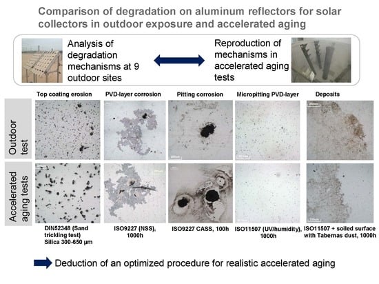
The five main degradation mechanisms that were detected during the outdoor testing campaign are the following:
  • Corrosion of the aluminum PVD layer
  • Micropitting in the PVD layer
  • Non-removable chemical deposition on the surface
  • Pitting corrosion
  • Sand abrasion
Table 3 summarizes the degradation mechanisms suffered for each material at every exposure site.
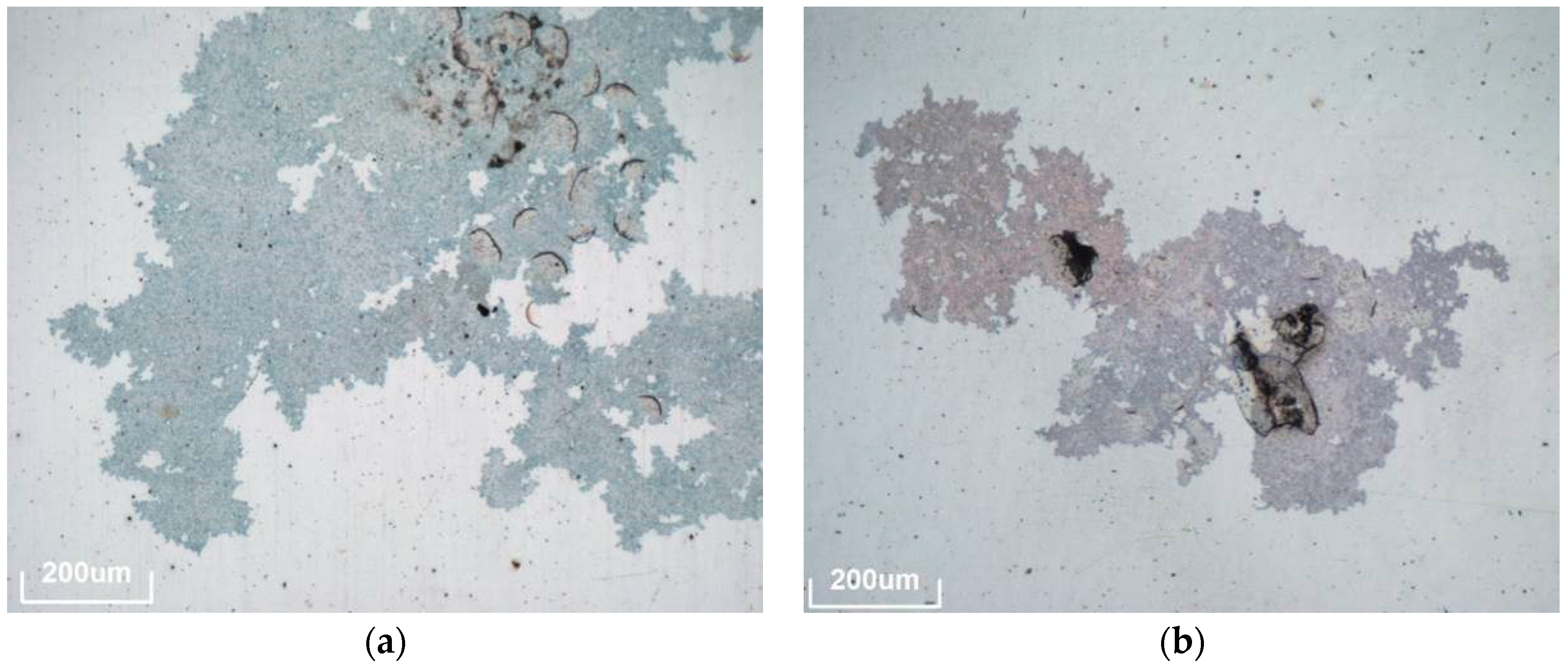
The first mechanism consists of a corrosion produced in the pure Al layer, which is typical for PVD-coated aluminum reflectors (materials A, B, C, D and F). A detailed description of this degradation mechanism can be found in [24]. Examples of this degradation type can be seen in Figure 3. According to results presented in Table 3, in general these corrosion defects mainly appeared in materials A, B, D and F (and also in samples C exposed in coastal sites after longer exposures, although with a lower intensity). For these four material types, PVD layer corrosion was detected in many sites already after 6 months. Typical spot sizes range between 100 μm and a few millimeters. The number of defects detected was higher for D and F samples and for aggressive climates (close to the coast), such as Tan Tan, and increased with the exposure time. Also on sites with severe abrasion, the extent of this defect type is elevated. Here the protective function of the top layers is decreased and the abrasive defects act as starting points for the corrosion.
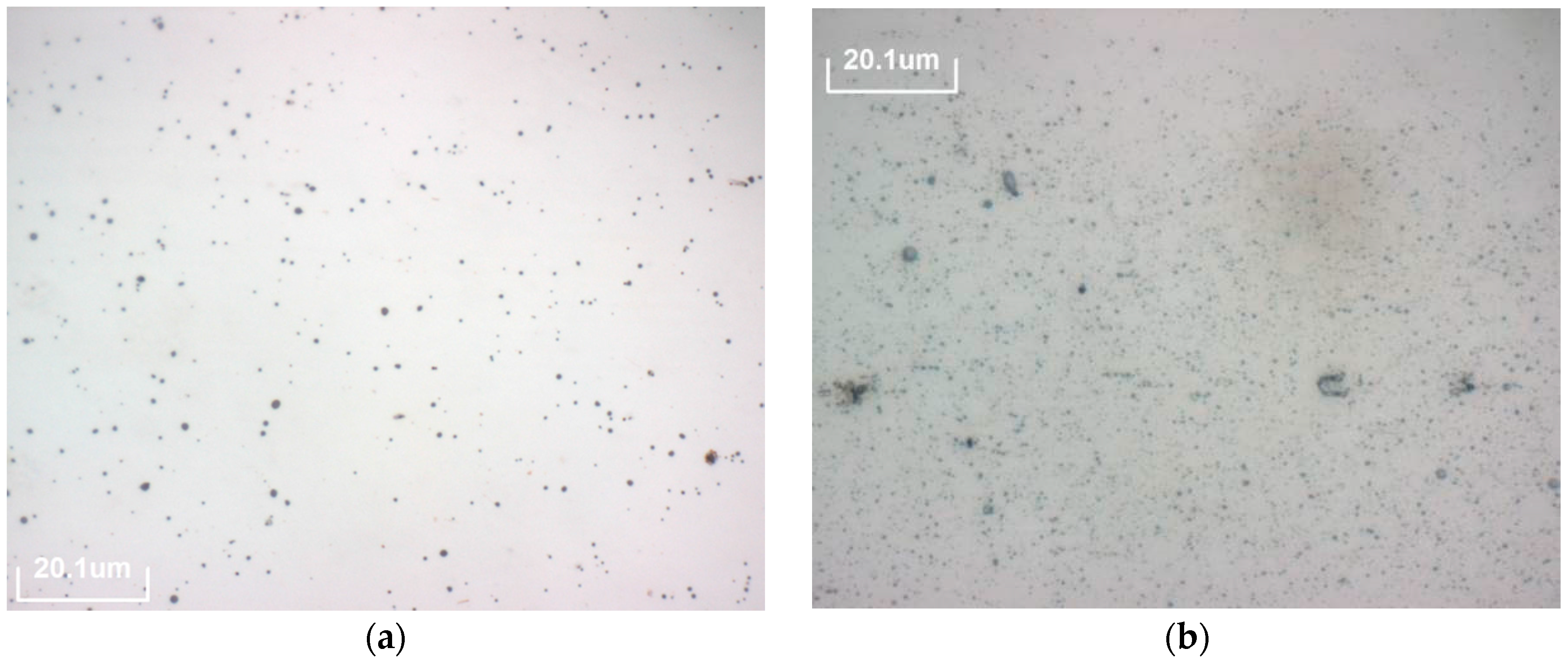
The second mechanism (micropitting) consists of small perforations of the aluminum PVD layer. Under the light microscope, these kinds of defects are visible as small black spots of a size below one micrometer. Micropitting is only observed on materials A, B and C, as indicated in Table 3. As all these samples are from one manufacturer it is likely that a characteristic in the production process causes this susceptibility. Typical spots in material C (see Figure 4 right) are smaller and denser than spots detected in material A and B (see 
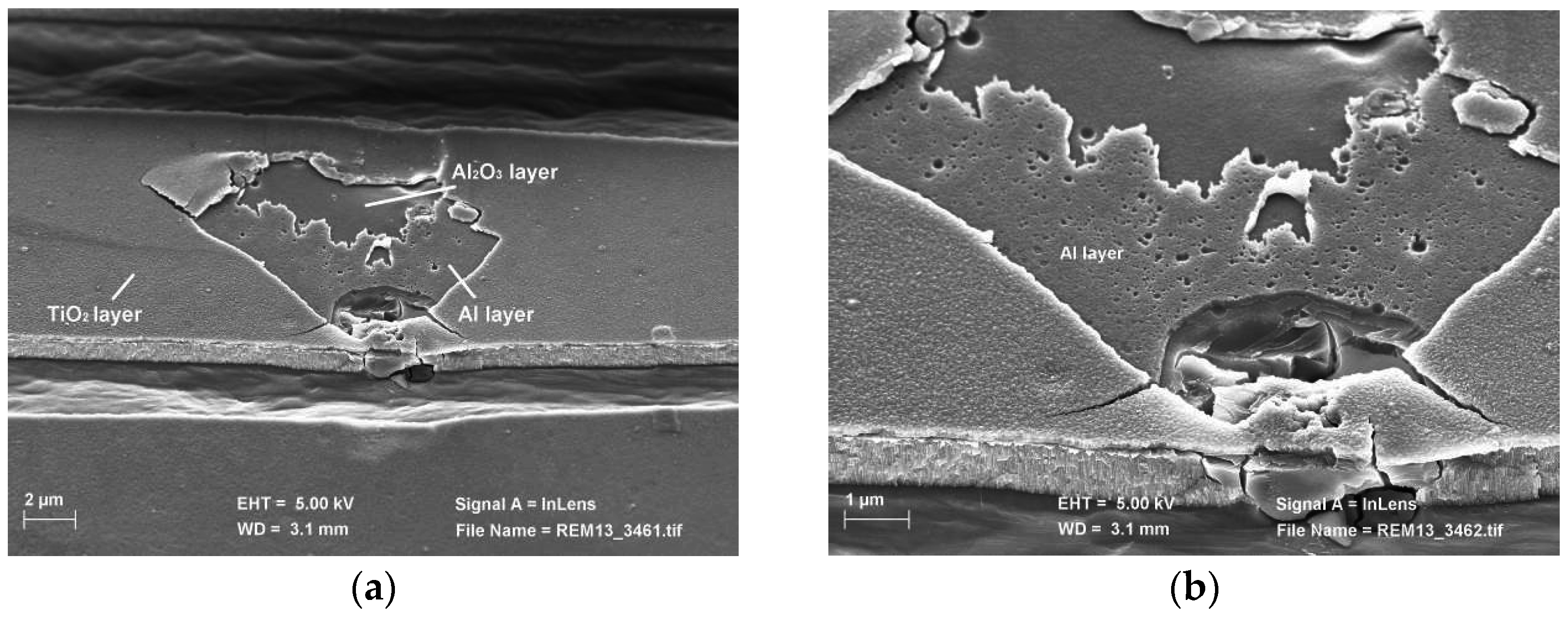
Figure 4 left). Micropitting degradation appeared in all exposure sites after 6 months. SEM images of the actual holes in the Al layer are presented in Figure 5. The damaged PVD layer system can be observed in the central part of the image presented in Figure 5 left, without the delaminated protective top coating. Figure 5 right shows a picture of the same area but with higher magnification. In this case, small holes can be easily observed in the Al layer, corresponding to the micropitting defects.
The third degradation mechanism detected consists of different kinds of deposits on the surface, which cannot be removed by the usual cleaning process (demineralized water and a soft tissue when necessary). The settled environmental particles seem to chemically interact with the protective coating (see Figure 6). As can be seen in Table 3, this is the most common defect observed in the outdoor exposure study because it was detected in all materials and all exposure sites.
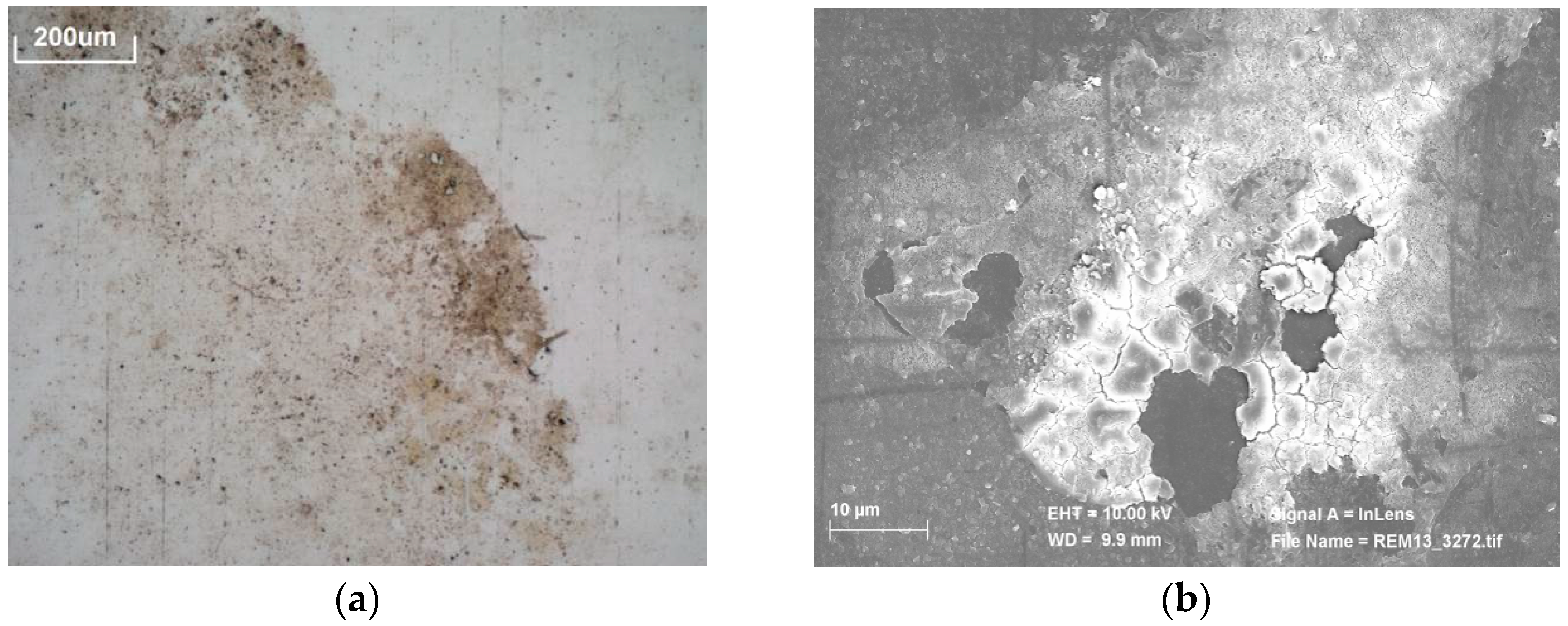
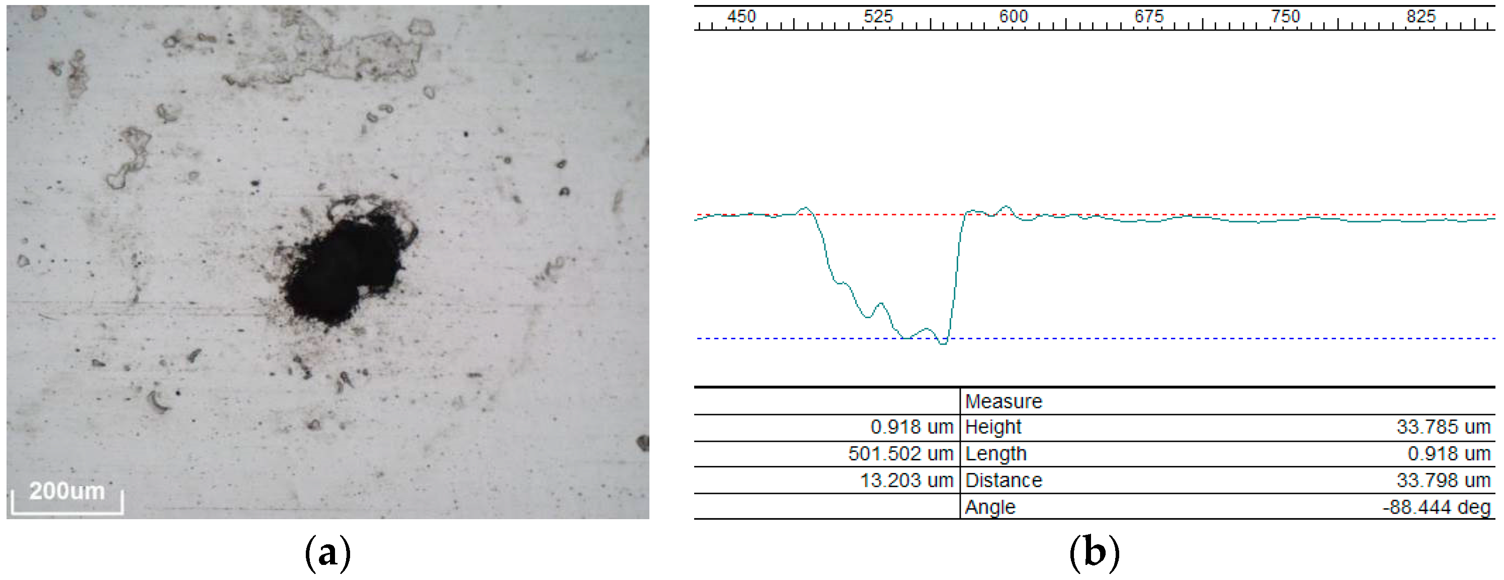
The fourth mechanism, called pitting corrosion, is a punctual corrosion that penetrates into the aluminum substrate (see Figure 7), presenting irregular shape and sizes around 100–200 μm. As can be noted in Table 3, this degradation mechanism almost exclusively happens on coastal sites (Almería, Canarias, Abu Dhabi and Tan Tan). A remarkable behavior was detected in Tan Tan, where most materials suffer this degradation already after 6 months of outdoor exposure (except C and E). For a deeper understanding, the pitting holes were observed with the 3D microscope, as seen in the profile of a cross section in Figure 7, right. As can be observed, the depth of a typical pitting hole is around 30–50 μm. In addition the areas surrounding pitting holes are often covered with corrosion products reaching considerable fractions of the samples. The formation of pitting holes in aluminum is associated with the presence of chloride ions [25], which explains the strong sensitivity to this degradation mechanism at the coastal sites.
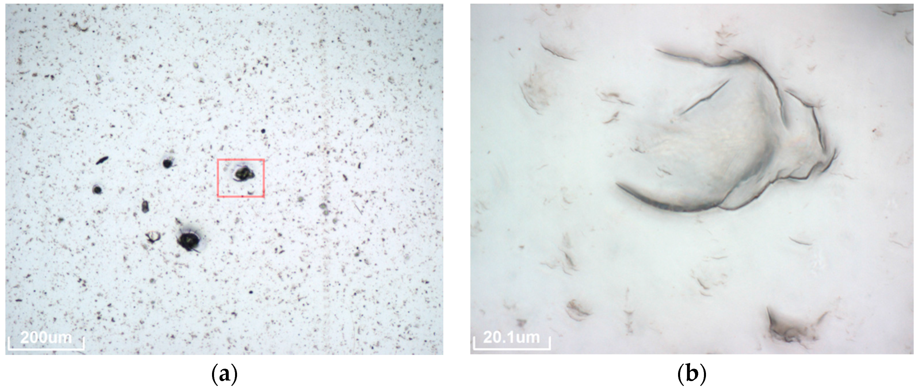
The fifth mechanism is an abrasive damage of the materials top coating caused by airborne dust and sand particles. The size of the defects ranges from few micrometers to around 0.5 mm. In Figure 8 an overview can be seen on the left and a higher magnification picture shows the different defects in the top coating on the right. So far this mechanism has only been detected at the desertic Moroccan sites.
The site of Zagora is especially aggressive concerning this mechanism as it appears after only 6 months and spreads over the entire surface of all samples with a high density and maximum defect size. In Erfoud and Missour the defects only appear after longer exposition durations and with less dense distribution as well as a smaller size.
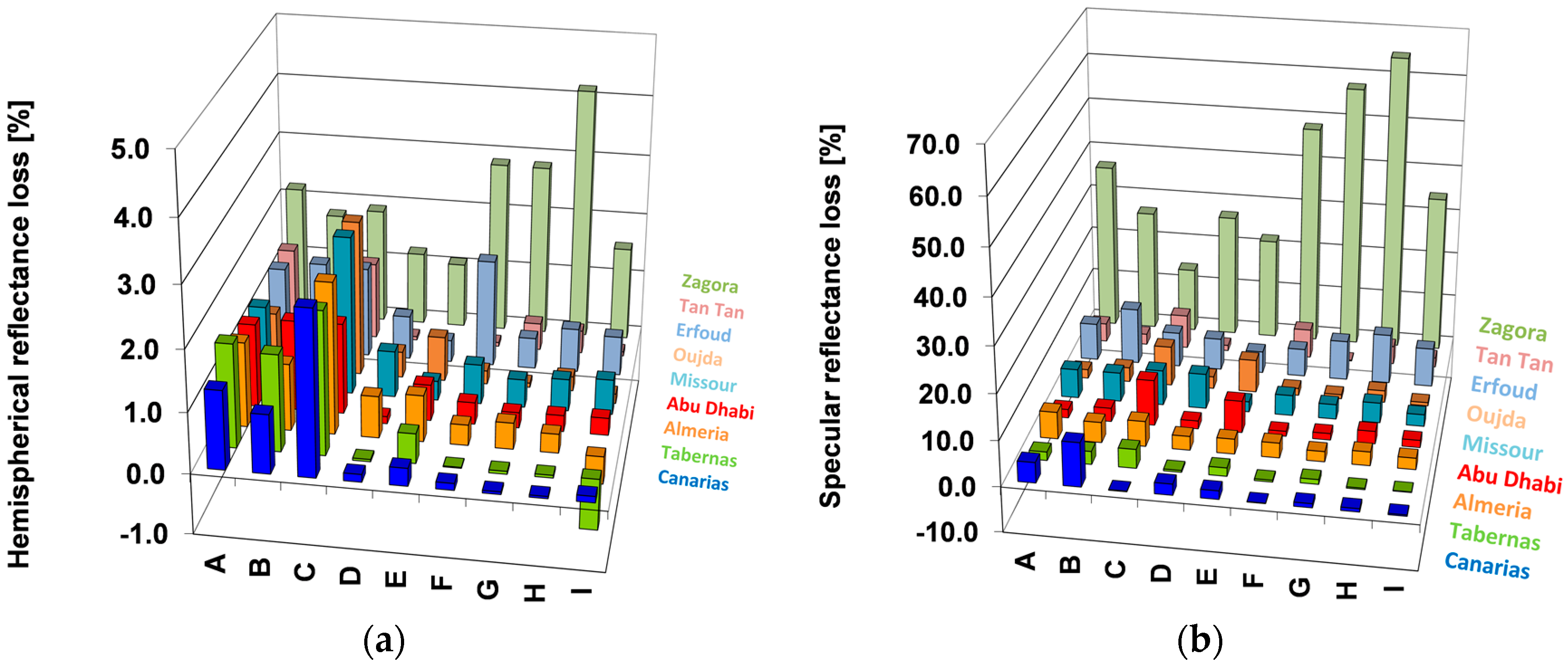
Additionally, reflectance was measured in all materials and all sites, after the testing period (see Figure 9.)
As can be seen in Figure 9, hemispherical reflectance losses are significantly lower than specular reflectance losses, because the main process causing the losses is scattering. Concerning the reflectance decay for the different materials, it can be noticed that in general materials A, B and C show higher losess (mainly in hemispherical reflectance due to the micropitting). And with respect to the sites, the most significant result is that Zagora (and also Erfoud, but in a lower importancy) suffered a considerably higher reflectance decrease. In this site, materials F, G and I present the highest reflectance losses. These results are useful for a better understanding of the performance behaviour of the different materials in the studied sites. However, reflectance measurements are not able to distinguish among the different degradation mechanisms and, consequently, they do not show a clear patterns because all possible effects are mixed. Therefore, reflectance loss was not selected as a representative parameter to derive proper accelerated aging tests that reproduce the degradation suffered in the real outdoor conditions.

3.2. Accelerated Testing

Table 4 summarizes the results of the accelerated aging tests performed with the different materials. The columns show the typical degradation mechanisms that were already discussed in the outdoor testing (see Section 3.1) and the rows represent the accelerated aging tests conducted. There is an additional column, titled “Side Effects,” where degradation mechanisms that do not happen during outdoor exposure are included. Images of typical appearances of the side effects are linked in the table. This way it can be directly seen which test has which effect on a material. The effects of the two abrasion tests (soil pipe and sandstorm) are not included in this table because they are specifically designed as short-term mechanical tests and thus only reproduce abrasive defects.
From the results of the conventional test program, the following conclusions can be drawn:
  • The PVD-layer corrosion can be provoked in the NSS test in materials A, B, D and F (see Figure 10a), but not as strong as detected in coastal outdoor sites. It only appears sporadically and mainly on surface damages. The CASS test does reproduce this corrosion type (in materials A, B, C, D and F) even for only 100 h of testing, but always accompanied by strong pitting. Finally, this degradation mechanism was also detected in material B during the Humidity Freeze test (where materials B, E and F were included) and also during the immersion test (where materials B, E and I were tested). Again in the last two tests it only appeared to a very small extent.
  • Micropitting only appears in the UV + Condensation test in materials A, B and C (see Figure 10b) and in the Damp Heat test (material C).
  • The deposits on the surface were not reproduced with the conventional tests applied.
  • Pitting corrosion was only reproduced in the CASS test (see Figure 10c). In this case, the pits found in all materials were bigger, more numerous and with more deposits around the spots than those detected in outdoor exposure tests (see Figure 10d).
  • Abrasion defects are only detected in the tests including mechanical impacts of particles, whether it is from falling particles in the soil pipe (Figure 10p) or in the air stream of the sandstorm chamber (Figure 10o).
Additionally, the following side effects not detected outdoors were also found in the conventional accelerated tests:
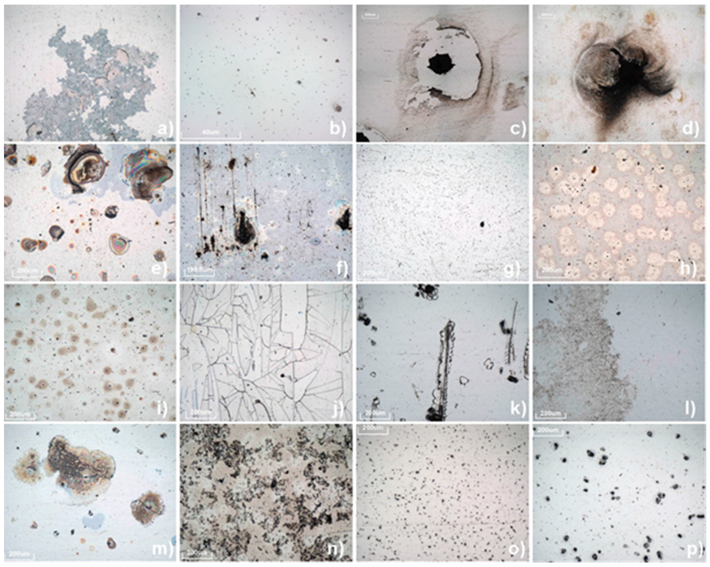
  • A particular defect was detected in materials A, B and C after the NSS test, consisting of cracks in the top layers together with their delamination (see Figure 10e,f). This effect was also found in material B after the immersion test.
  • Some unrealistic deposits were detected in all materials after the Damp Heat test, covering large parts of the sample surfaces (see Figure 10g).
  • In the UV + Condensation and the Damp Heat tests, the elevated temperature is likely to cause degradation of the polymer top coating of material C. Pictures of these unrealistic changes in the polymer layer are presented in Figure 10h (Damp Heat test) and Figure 10i (UV + Condensation test).
  • Additionally, another side effect appeared in the UV + Condensation test (in materials A, B, D, E and F), consisting of a significant amount of cracks in the top layers (see Figure 10j).
  • Finally, some scratches were detected in materials A and F after the Humidity Freeze test (see Figure 10l).
In the first innovative test performed, a combination of the NSS and the UV + Condensation test was chosen to benefit from the advantages of both tests. This test was only applied to a small set of materials (A, E and I). As can be seen in Table 4, material A suffered from both PVD- layer corrosion and micropitting corrosion in this test. In addition, it is worth to remark that the typical cracks detected in the UV + Condensation test (see Figure 10j) also appeared in this combined test, in materials A and E.
In the outdoor results, indications were found that the soiling has an influence on the degradation behavior. In general, samples with stronger soiling also showed more other defects. Therefore, a series of tests with artificially soiled samples has been carried out. The soiled samples have been tested in conventional tests. The first important result is that the Tabernas dust indeed seems to enhance corrosion mechanisms. In particular, the following events were detected:
  • In the UV + Condensation + Sand test (material B and F) as well as in the Damp Heat + Sand test (material D), PVD-layer corrosion was detected on soiled samples, although this was not the case for clean samples. This degradation mechanism was also found in the Humidity Freeze + Sand test (materials B and F) and the NSS + Sand test (material B), but in this case the results are not as significant because it was also noticed in the same tests without sand. It is important to highlight that the corrosion that appeared in the two tests was stronger than those detected in the same test without sand.
  • Micropitting corrosion was only detected in the conventional tests when Damp Heat or UV + Condensation conditions were applied. However, when sand is added on the sample surfaces, this degradation pattern was detected not only in these two tests, but also in the NSS test (for material B).
  • The effect of incompletely removable deposits on the samples, observed after the outdoor tests, is reproduced by all the innovative accelerated aging tests with sand (see Figure 10l).
  • Finally, pitting corrosion was not noticed on the innovative tests performed with sand.
  • There are two main factors explaining the higher susceptibility to degradation of the soiled samples. First, soiling changes the wetting phenomena on the sample surface. While clean samples are very hydrophobic, soiled surfaces tend to retain humidity and thus stay wet for a longer duration during exposure. Second, as natural sand includes many different impurities, aggressive compounds like chlorides can be introduced which act as corrosion activators.
  • The same side effects observed in the conventional tests were also detected in the tests with sand. For example, cracks in the UV + Condensation+Sand and the Humidity Freeze + Sand tests. In addition, innovative tests presented some side effects caused by the sand application, that is, NSS + Sand test showed noticeable deterioration points (materials B and C, see Figure 10m) and sand could not be removed from the sample surface of material C both in the Damp Heat +Sand test and in the UV + Condensation + Sand test (see Figure 10n).

4. Conclusions

The outdoor exposure of nine different aluminum mirror types tested at nine exposure sites showed that the type and amount of degradation depends on materials and location. However, five generic degradation mechanisms have been detected: aluminum corrosion of the pure PVD-Al layer, micropitting of the pure PVD-Al layer, pitting corrosion of the Al substrate, mechanical top coating degradation, and non-removable surface deposits due to chemical interaction between local dust particles and the protective coatings of the reflector samples.
Degradation is more severe on sites close to the coast and on sites with high wind velocities and airborne sand particles. Materials with reflectance enhancing PVD layers show improved reflectance but also a higher susceptibiltiy to degradation. Some mechanisms only appear on these materials and one mechanism even originates from a distinctive feature of the production process of one manufacturer.
The same sample types have been tested in a large accelerated aging testing campaign including standardized and innovative tests. Standardized tests only reproduced a maximum of one or two of the five mechanisms detected outdoors. Some of the short term tests do not provoke any degradation at all. In addition, several degradation effects that were not observed outdoors appeared. A realistic degradation pattern was thus not obtained for any of the conventional tests. The difference in material behavior concerning the mechanisms is similar to the one found during outdoor exposure.
The innovative accelerated aging tests of artificially soiled samples with Tabernas dust were able to reproduce three of the five mechanisms observed outdoors. None of the standard tests reproduce the “deposit on surface” degradation, though it is systematically reproduced by the innovative tests including soiling. Unrealistic side degradation mechanisms like top coating cracking have not been prevented in these cases. However, a more realistic overall degradation pattern was observed compared to standardized testing of clean surfaces. The investigation of this approach is ongoing to identify the best suited parameters (regarding soil application, test conditions and repeatability).
Although there was no single test that produced a perfectly realistic degradation pattern, the results of this study enable researchers to identify more realistic tests to combine them into a testing sequence. With this approach more mechanisms can be reproduced at once. It can also help avoid using tests and test durations with unrealistic side effects.
The research results presented in this paper are a useful tool for aluminum-reflector manufacturers to design and perform their accelerated aging testing strategy in order to improve the manufacturing process and product quality. In addition, significant information about real degradation mechanisms to be resolved at different representative sites is presented, giving the manufacturers not only the approach to be followed to advance with their products, but also possible specific sites to be avoided when recommending them. The comparisons made in the course of this investigation also built a base for the testing procedure for aluminum reflectors that was published via the SolarPaces program [26]. This testing procedure is a powerful tool for research laboratories to serve as independent institutions in the comparison and validation of the prototype or marketed aluminum-reflectors.

Acknowledgments

Financial support from the German ministry for the environment, nature conservation and nuclear safety (BMU) within the contract 0325420 is gratefully acknowledged. The authors want to thank ITC Gran Canaria (especially Juan Antonio Suarez Ortega), MASDAR (especially Ali Al Masabai), IRESEN and the Mohammed First University in Oujda for hosting the outdoor exposure racks and sending the samples to the PSA. Also, Lucia Martínez from the Centro de Investigaciones Energéticas, Medioambientales y Tecnológicas (CIEMAT), Tomás Jesús Reche Navarro from EULEN, Florian Wiesinger, Alexander Oschepkov and Peter Heller from DLR for their valuable contributions.

Author Contributions

Johannes Wette, Florian Sutter and Aránzazu Fernández-García were responsible for the execution of the exposure and testing campaign as well as the analysis of the materials. The whole campaign was planned in collaboration with Stefan Ziegler and Reinhard Dasbach as material experts, and they also contributed to the interpretation of the results. Johannes Wette wrote the article with much collaboration from Florian Sutter and Aránzazu Fernández-García.

Conflicts of Interest

The authors declare no conflict of interest.

Nomenclature and Units

ρs,φ (660 nm; 15°; 12.5 mrad)monochromatic specular reflectance at wavelength 660 nm, incidence angle 15° and acceptance angle 12.5 mrad(%)
Ttemperature(°C)
r.H.relative humidity(%)
vwind velocity(m/s)
dparticle diameter(µm)

Acronyms

CASScupro-acetic acid salt spray
CPCcompound parabolic concentrators
CSPConcentrated solar power
NSSneutral salt spray
PSAPlataforma Solar de Almería
PTCparabolic-trough collectors
PVDPhysical vapor deposition
SEMscanning electron microscope

References

  1. International Energy Agency. Key World Energy Statistics; International Energy Agency: Paris, France, 2015. [Google Scholar]
  2. Do, T.-T.-H.; Schnitzer, H.; Le, T.-H. A decision support framework considering sustainability for the selection of thermal food processes. J. Clean. Prod. 2014, 78, 112–120. [Google Scholar] [CrossRef]
  3. Kalogirou, S. The potential of solar industrial process heat applications. Appl. Energy 2003, 76, 337–361. [Google Scholar] [CrossRef]
  4. Fernández-García, A.; Rojas, E.; Pérez, M.; Silva, R.; Hernández-Escobedo, Q.; Manzano-Agugliaro, F. A parabolic-trough collector for cleaner industrial process heat. J. Clean. Prod. 2015, 89, 272–285. [Google Scholar] [CrossRef]
  5. Harmin, A.; Merzouk, M.; Boukar, M.; Amar, M. Design and experimental testing of an innovative building-integrated box type solar cooker. Sol. Energy 2013, 98, 422–433. [Google Scholar] [CrossRef]
  6. Narasimha Rao, A.V.; Subramanyam, S. Solar cookers—Part I: Cooking vessel on lugs. Sol. Energy 2003, 75, 181–185. [Google Scholar] [CrossRef]
  7. Fernández-García, A.; Zarza, E.; Valenzuela, L.; Pérez, M. Parabolic-trough solar collectors and their applications. Renew. Sustain. Energy Rev. 2010, 14, 1695–1721. [Google Scholar] [CrossRef]
  8. European Solar Thermal Electricity Association (ESTELA). Solar Thermal Electricity, Strategic Research Agenda 2020–2025; ESTELA: Brussels, Belgium, 2012. [Google Scholar]
  9. International Energy Agency (IEA). Technology Roadmap: Solar Thermal Electricity; IEA: Paris, France, 2014. [Google Scholar]
  10. García-Segura, A.; Fernández-García, A.; Ariza, M.J.; Valenzuela, L.; Sutter, F. Durability studies of solar reflectors: A review. Renew. Sustain. Energy Rev. 2016, 62, 453–467. [Google Scholar] [CrossRef]
  11. Wiesinger, F.; Sutter, F.; Fernández-García, A.; Reinhold, J.; Pitz-Paal, R. Sand erosion on solar reflectors: Accelerated simulation and comparison with field data. Sol. Energy Mater. Sol. Cells 2016, 145, 303–313. [Google Scholar] [CrossRef]
  12. Kennedy, C.E.; Terwilliger, K.; Milbourne, M. Development and Testing of Solar Reflectors; Technical Report No. NREL/CP-520-36582; National Renewable Energy Laboratory (NREL): Golden, CO, USA, 2004.
  13. Kennedy, C.E.; Terwilliger, K. Optical durability of candidate solar reflectors. J. Sol. Energy Eng. 2005, 127, 262–268. [Google Scholar] [CrossRef]
  14. Sutter, F.; Ziegler, S.; Schmücker, M.; Heller, P.; Pitz-Paal, R. Modelling of optical durability of enhanced aluminum solar reflectors. Sol. Energy Mater. Sol. Cells 2012, 107, 37–45. [Google Scholar] [CrossRef]
  15. International Organization for Standardization (ISO). ISO 9227: 2012-05: Corrosion Tests in Artificial Atmospheres—Salt Spray Tests; ISO: Geneva, Switzerland, 2012. [Google Scholar]
  16. International Electrotechnical Commission (IEC). IEC 62108:2007: Concentrator Photovoltaic (CPV) Modules and Assemblies—Design Qualification and Type Approval; IEC: Geneva, Switzerland, 2007. [Google Scholar]
  17. International Organization for Standardization. ISO 11507: 2007-02: Paints and Varnishes—Exposure of Coatings to Artificial Weathering—Exposure to Fluorescent UV Lamps and Water; ISO: Geneva, Switzerland, 2007. [Google Scholar]
  18. International Organization for Standardization (ISO). ISO 6988:2012, Metallic and Other Non-Organic Coatings—Sulfur Dioxide Test with General Condensation of Moisture; ISO: Geneva, Switzerland, 2012. [Google Scholar]
  19. Deutsches Institut für Normung. DIN 50018: 2013-05, Testing in a Saturated Atmosphere in the Presence of Sulfur Dioxide; Deutsches Institut für Normung: Berlin, Germany, 2013. [Google Scholar]
  20. QUALICOAT. Specifications for a Quality Label for Liquid and Powder Organic Coatings on Aluminum for Architectural Applications, 13th ed.; QUALICOAT: Zurich, Switzerland, 2012. [Google Scholar]
  21. Deutsches Institut für Normung. DIN 52348: Testing of Glass and Plastics—Abrasion Test—Sand Trickling Method; Deutsches Institut für Normung: Berlin, Germany, 1985. [Google Scholar]
  22. Department of Defense. MIL-STD-810G: Environmental Engineering Considerations and Laboratory Tests; Department of Defense: Philadelphia, PA, USA, 2008.
  23. Sutter, F.; Fernandez-García, A.; Wette, J.; Heller, P. Comparison and Evaluation of Accelerated Aging Tests for Reflectors. In Proceedings of the SolarPACES 2013 International Conference, Las Vegas, NV, USA, 17–20 September 2013.
  24. Sutter, F.; Wette, J.; Lopez-Martin, R. Corrosion of Aluminum Solar Reflectors. In Proceedings of the International Conference on Concentrating Solar Power and Chemical Energy Systems, SolarPACES 2012, Marrakesh, Morocco, 11–14 September 2012.
  25. Szlarska-Smialowska, Z. Pitting corrosion of aluminum. Corros. Sci. 1999, 41, 1743–1767. [Google Scholar] [CrossRef]
  26. Sutter, F.; Wette, J.; Fernández-García, A.; Ziegler, S.; Dasbach, R. Accelerated aging testing of aluminum reflectors for concentrated solar power. In SolarPaces Guideline; SolarPACES: Almería, Spain, 2016. [Google Scholar]
Figure 1. (a) Layer structure of materials A, B, C, D and (b) materials E, G, H, I.
Energies 09 00916 g001
Figure 2. Exposure sites in North Africa and Spain (a); typical exposure rack (b).
Energies 09 00916 g002
Figure 3. Microscopic views of degradation due to corrosion of the aluminum PVD layer. (a) material D after 6 months outdoor; (b) material B after 12 months.
Energies 09 00916 g003
Figure 4. Microscopic images of degradation due to micropitting corrosion in material A (a) and C (b) after 12 months in Almería.
Energies 09 00916 g004
Figure 5. SEM image of micropitting corrosion in the Al layer of the same spot at two magnifications, 2 μm (a) and 1 μm (b).
Energies 09 00916 g005
Figure 6. Microscopic (a) and SEM image (b) of deposits on the surface of material A.
Energies 09 00916 g006
Figure 7. Microscopic image of the degradation due to pitting corrosion in material H (a) and depth profile of typical spot (b).
Energies 09 00916 g007
Figure 8. Microscopic view of sand abrasion produced in material A from Zagora, 10× magnification (a) and 100× magnification of the red square area in the left picture (b).
Energies 09 00916 g008
Figure 9. Hemispherical (a) and specular (b) reflectance loss after the outdoor exposure for all materials and sites.
Energies 09 00916 g009
Figure 10. (a) PVD corrosion in material D after the NSS test (compare to outdoor results in Figure 3); (b) Micropitting in material A after the UV + Condensation test (compare to outdoor results in Figure 4); (c) Pitting corrosion in material G after the CASS test (compare to outdoor results in Figure 7); (d) Strong Pitting corrosion after the CASS test (detected in all materials); (e) Cracks and delamination in material A after the NSS test; (f) Cracks and delamination in material C after the NSS test; (g) Deposits on sample surface after the Damp Heat test (detected in all materials); (h) Layer changes in material C after the Damp Heat test; (i) Layer changes in material C after the UV + Condensation test; (j) Cracks in material F after the UV + Condensation test; (k) Scratches in material A after the Humidity freeze test; (l) Surface deposits on the surface of material A after the UV + Condensation test with sand (compare to outdoor results in Figure 6); (m) Deterioration in material B after the NSS + Sand test; (n) Non-removable sand deposits in material C after the Damp Heat + Sand tests; (o) Abrasion defects after sandstorm chamber test; (p) Abrasion defects after soil pipe test.
Energies 09 00916 g010
Table 1. Specular reflectance and structure of the different materials tested.
ManufacturerMaterialMonochromatic Specular Reflectance ρs,φ (660 nm; 15°; 12.5 mrad)Al2O3 Layer Thickness (µm)PVD CoatingProtective Coating Thickness and Type
1A0.842 ± 0.0060.9Yes2.2 µm SiO2 Sol Gel type 1
B0.839 ± 0.0070.9Yes2.2 µm SiO2 Sol Gel type 2
C0.797 ± 0.0080.8Yes6.5 µm Polymer type 1
2D0.815 ± 0.0101.4Yes2.5 µm SiO2 Sol Gel type 3
E0.788 ± 0.0010.3No3.0 µm Polymer type 2
F0.827 ± 0.0051.1Yes2.2 µm SiO2 Sol Gel type 4
3G0.804 ± 0.0040.05No2.8 µm SiO2 Sol Gel type 5
H0.774 ± 0.0060.05No2.2 µm SiO2 Sol Gel type 6
I0.723 ± 0.0170.4No2.5 µm SiO2 Sol Gel type 7
Table 2. Description of performed accelerated aging tests.
TestStandardTesting Time (h)Testing ConditionsMaterials Tested
NSS aISO 9227 [15]3000[NaCl] = 50 ± 5 g/L; T = 35 ± 2 °C; r.H. = 100%; pH = 6.5–7.2All
CASS aISO 9227 [15]100[NaCl] = 50 ± 5 g/L; [CuCl2] = 0.26 ± 0.02 g/L; T = 50 ± 2 °C; r.H. = 100%; pH = 3.1–3.3All
Damp Heat aIEC 62108 [16]2000T = 85 ± 2 °C; r.H. = 85% ± 5%All
UV + Condensation aISO 11507 [17]20004 h: UV (340 nm); T = 60 ± 3 °C 4 h: T = 50 ± 3 °C; r.H. = 100%All
Humidity Freeze aIEC 62108 [16]1500400 cycles: T from −40 to 65 °C (10 min in maximum and minimum T) 40 cycles: 20 h T = 65 °C; r.H. = 85% ± 5% + 4 h T = −40 °CAll
Kesternich aISO 6988 [18] and DIN 50018 [19]84035 cycles: 8 h [SO2] = 0.067%; T = 40 ± 3 °C; r.H. = 100% + 16 h ambient T and r.H.All
UV a-2000300 W/m2; ambient T and r.H.All
Machu aQualicoat [20]48T = 37 °C; [NaCl] = 50 ± 1 g/L; [H2O2] = 5 ± 1 mL/L; [CH3COOH] = 10 ± 1 mL/LAll
Immersion a-1000[NaCl] = 50 ± 5 g/L; Ambient TB, E, I
NSS/UV + Cond b-10001 week NSS, 1 week UV + CondensationA, E, I
NSS + Sand b-1000[NaCl] = 50 ± 5 g/L; T = 35 ± 2 °C; r.H. = 100%; pH = 6.5–7.2 Sand on the samplesB, C, E, F
Damp Heat + Sand b-1000T = 85 ± 2 °C; r.H. = 85% ± 5% Sand on the samplesC, D, I
UV + Cond + Sand b-10004 h: UV (340 nm); T = 60 ± 3 °C 4 h: T = 50 ± 3 °C; r.H. = 100% Sand on the samplesB, C, D, I
Humidity Freeze + Sand b-1000400 cycles: T from −40 to 65 °C (10 min in maximum and minimum T) 40 cycles: 20 h T = 65 °C; r.H. = 85% ± 5% + 4 h T = −40 °C Sand on the samplesB, E, F
Soil pipe bDIN 52348 [21] 5–600 g sand, SiO2 d = 300–625 µmAll
Sandstorm chamber bMIL-STD 810G [22] 10 min, v = 12.5 m/s, [SiO2] = 125 mg/m3All
a Conventional test; b Innovative (non-standardized) test.
Table 3. Material type presenting each degradation mechanism under outdoor exposure testing, for every exposure site.
LocationExposure Time (Months)PVD Layer CorrosionMicropitting in the PVD LayerDeposits on the SurfacePitting CorrosionSand Abrasion
Tabernas (Spain)6-A, B, CAll--
18B, DA, B, CAll--
24D, FA, B, CAllF-
Almeria (Spain)6A, B, DA, B, CAll--
18A, B, C, D, FA, B, CAllA, B, D, F, G, H, I-
24A, B, C, D, FA, B, CAllA, B, D, F, G, H, I-
Abu Dhabi (UAE)6A, B, D, FA, B, CAllE-
18A, B, DA, B, CAllA, B, G, H-
24A, B, D, FA, B, CAllA, B, D, G, H, I-
Canarias (Spain)6A, B, D, FA, B, CAllA, B, C-
18A, B, C, DA, B, CAllA, B, C, D, E, F, I-
24A, B, C, D, FA, B, CAllAll-
Oujda (Morocco)6-A, B, CAll--
18A, B, D, FA, B, CAllH-
24B, D, FA, B, CAll--
Missour (Morocco)6-A, B, CAll--
20B, D, FA, B, CAll-All
24D, FA, B, CAll-All
Erfoud (Morocco)6A, B, D, FA, B, CAll--
20A, B, D, FA, B, CAll-All
24A, B, C, D, FA, B, CAllHAll
Zagora (Morocco)6A, B, D, FA, B, CAll-All
20A, B, D, FA, B, CAll-All
24A, B, D, FA, B, CAll-All
Tan Tan (Morocco)6A, B, D, FA, B, CAllA, B, D, F, G, H, I-
20A, B, C, D, FA, B, CAllA, B, D, F, G, H, I-
24A, B, C, D, FA, B, CAllA, B, D, F, G, H, I-
Table 4. Degradation mechanisms of the different materials under accelerated aging testing.
TestExposure Time (Hours)PVD Layer CorrosionMicropitting in the PVD LayerDeposits on the SurfacePitting CorrosionSide EffectsTested
NSS a1000D, F----All
2000A, B, D, F---A, B, C: cracks, delamination (Figure 10e,f)All
3000A, B, D, F---A, B, C: cracks, delamination (Figure 10e,f)All
CASS a100A, B, C, D,F--AllAll: strong pitting (Figure 10d)All
Damp Heat a2000-C--All: unrealistic deposition (Figure 10g) C: layer changes (Figure 10h)All
UV + Condensation a2000-A, B, C--A, B, D, E, F: cracks (Figure 10i) C: layer changes (Figure 10j)All
Humidity Freeze a1500B---B, F: scratches, cracks (Figure 10k)B, E, F
Kesternich a840-----All
UV a1000-----All
Machu a48-----All
Immersion a1000B---B: delamination, cracks (Figure 10e,f)B, E, I
NSS/UV + Cond b1000AA--A, E: cracks (Figure 10j)A, E, I
NSS + Sand b1000BBB, C, E, F-B, C: delamination, cracks, deterioration (Figure 10m)B, C, E, F
Damp Heat + Sand b1000DCC, D-C: sand cannot be removed (Figure 10n)C, D, I
UV + Cond/Sand b1000B, FA, B, CA, C, I-A, B, D: cracks (Figure 10j) C: sand cannot be removed (Figure 10n)A, B, C, D, F, I
Humidity Freeze + Sand b1000B, F-B, D, E-B, D: cracks (Figure 10k)B, E, F
a Conventional test; b Innovative (non-standardized) test.

