Article

Coil Design for High Misalignment Tolerant Inductive Power Transfer System for EV Charging

1
Power Electronics and Renewable Energy Research Laboratory (PEARL), Department of Electrical Engineering, University of Malaya, Kuala Lumpur 50603, Malaysia
2
School of Engineering, Deakin University, Waurn Ponds, VIC 3216, Australia
*
Author to whom correspondence should be addressed.
Energies 2016, 9(11), 937; https://doi.org/10.3390/en9110937
Submission received: 8 August 2016 / Revised: 22 October 2016 / Accepted: 25 October 2016 / Published: 10 November 2016
(This article belongs to the Collection Electric and Hybrid Vehicles Collection)

Abstract

:
The inductive power transfer (IPT) system for electric vehicle (EV) charging has acquired more research interest in its different facets. However, the misalignment tolerance between the charging coil (installed in the ground) and pick-up coil (mounted on the car chassis), has been a challenge and fundamental interest in the future market of EVs. This paper proposes a new coil design QDQ (Quad D Quadrature) that maintains the high coupling coefficient and efficient power transfer during reasonable misalignment. The QDQ design makes the use of four adjacent circular coils and one square coil, for both charging and pick-up side, to capture the maximum flux at any position. The coil design has been modeled in JMAG software for calculation of inductive parameters using the finite element method (FEM), and its hardware has been tested experimentally at various misaligned positions. The QDQ coils are shown to be capable of achieving good coupling coefficient and high efficiency of the system until the misalignment displacement reaches 50% of the employed coil size.

1. Introduction

The inductive power transfer (IPT) system has proved to be a successful technology for wireless charging of electric vehicles (EVs) [1,2,3,4]. Due to the reasonable electrical isolation between charging coil (paved in the road) and pick-up coil (embedded in the car chassis), the IPT system has the capability to operate in grimy conditions [5]. The IPT system is viable because of its inherent advantages of safety, cleanliness and its operation in the dirt, underwater, and harsh weather conditions [3,6]. For wireless charging of EVs, it is necessary to have a reasonable ground clearance of a few hundred millimeters between the road and the EV chassis, and the ground clearance is also known as the air gap between the charging coil and the pick-up coil [7].
In both dynamic and static charging of EVs through the IPT system, there are certain chances of alignment displacement between the charging and the pick-up coil. The position of EVs hampers magnetic coupling [3,8,9]. Thus, the IPT system should be capable of transferring the power under maximum possible misalignment between the coils [10,11]. At any misaligned position, the power transmission is substantially contingent on coupling coefficient [4,8,12]. The coupling coefficient is characterized by magnetic coupling between the coils and their geometric design [4,12,13,14,15,16,17].
Considering higher coupling coefficients initial coil designs with U-cores, E-cores, and pot cores were perused, but these were incompatible with EV due to their greater thickness. Mecke et al. in [18] used circular coils to transfer 1 kW at an air gap of 300 mm. They achieved 80% efficiency for the overall charging system but did not consider the misalignment. A 2 kW 700 mm diameter circular charging pad with 200 mm air gap was proposed [19]. The circular pads have exhibited good coupling but poor tolerance to misalignment because, when misalignment offset approaches ±40%, the output power reduces to zero [19]. To solve the issues of circular charging pads, the oval shape pads were presented. The oval charging pads were slightly more tolerant to misalignment than circular charging pads; however, they did not transfer high power transfer with the same specifications as those of circular pads. Budhia et al. [20] introduced and optimized a new polarized coupler called the Double D Quadrature (DDQ) that produced a flux path height twice that of circular charging pad together with a single sided flux path completely interoperable with circular pads.
Since the IPT has been a successful technology for EV charging, it draws considerable attention for the researchers to find high misalignment tolerant coils to see a future with the massive manufacture of EVs. This paper presents a new coil design named as QDQ (Quad D Quadrature) has been proposed to enhance the misalignment toleration of coils to a reasonable limit. The proposed design consists of four neighboring small circular coils (forming the slight shape of D) surrounded by a large square coil (forming Quadrature shape) that make a large single coil. Each time, all circular and square coils on charging and pick-up side are turned on to contribute to the resultant magnetic field. The proposed design supports a possible high coupling coefficient at different misaligned positions. To get accuracy in results, the inductive parameters have been calculated using finite element method (FEM) in JMAG software (version 14.0, JSOL Corporation, Tokyo, Japan) and also compared with measured values. Extensive experimental tests have been carried out to validate the functionality of the proposed coil at different misaligned positions of coils with respect to each other. The results have promising efficiency at reasonable misalignment

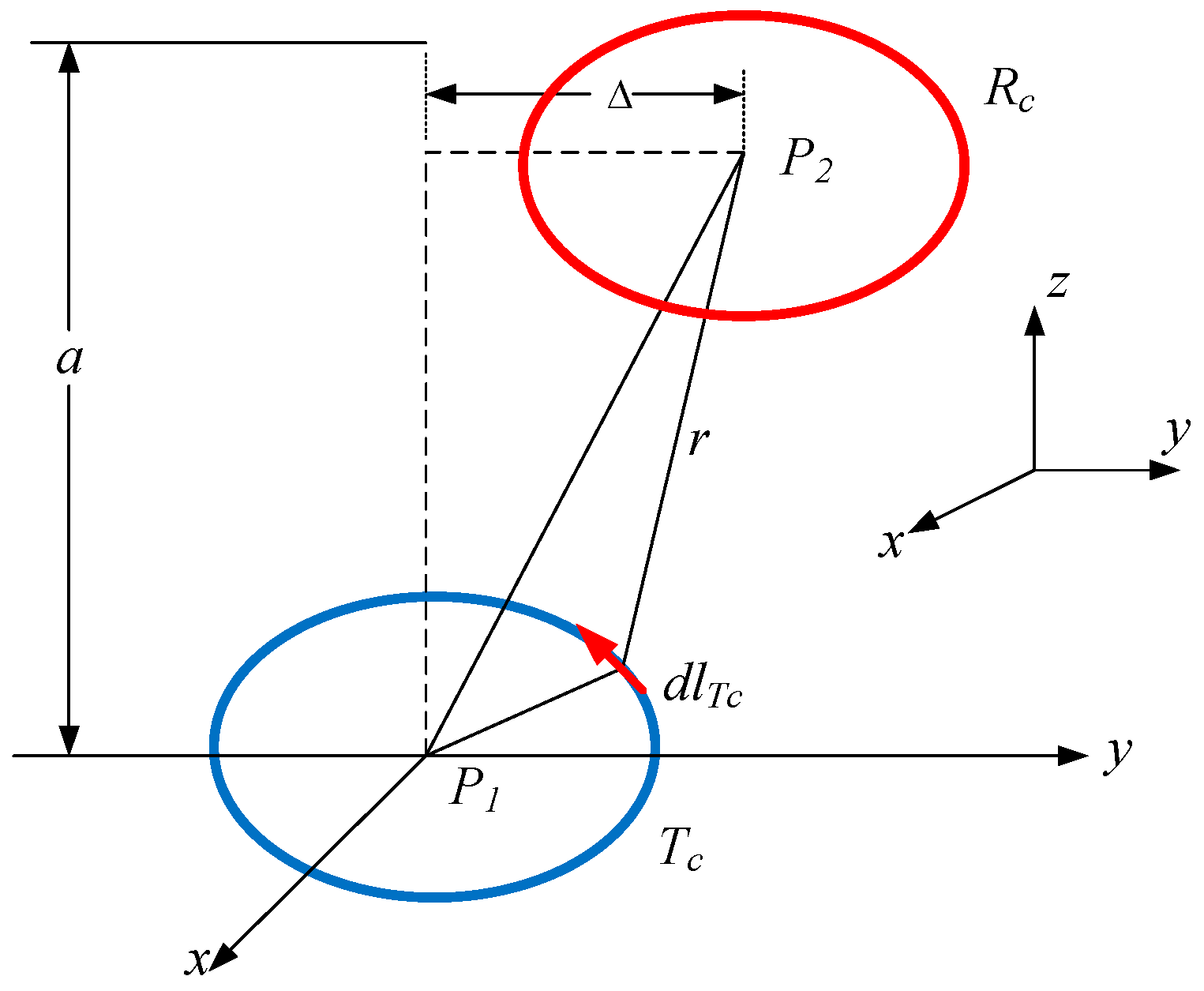
2. Proposed Coil Design
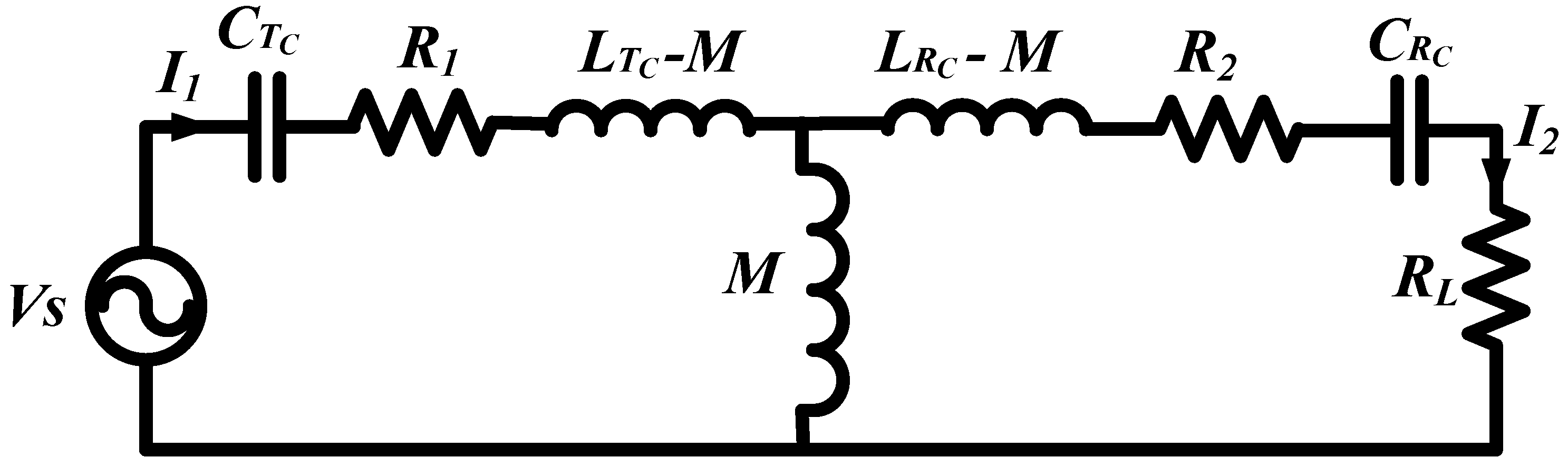
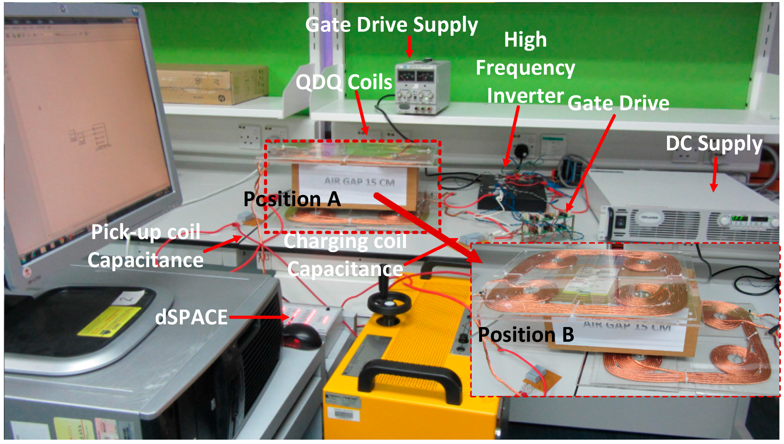
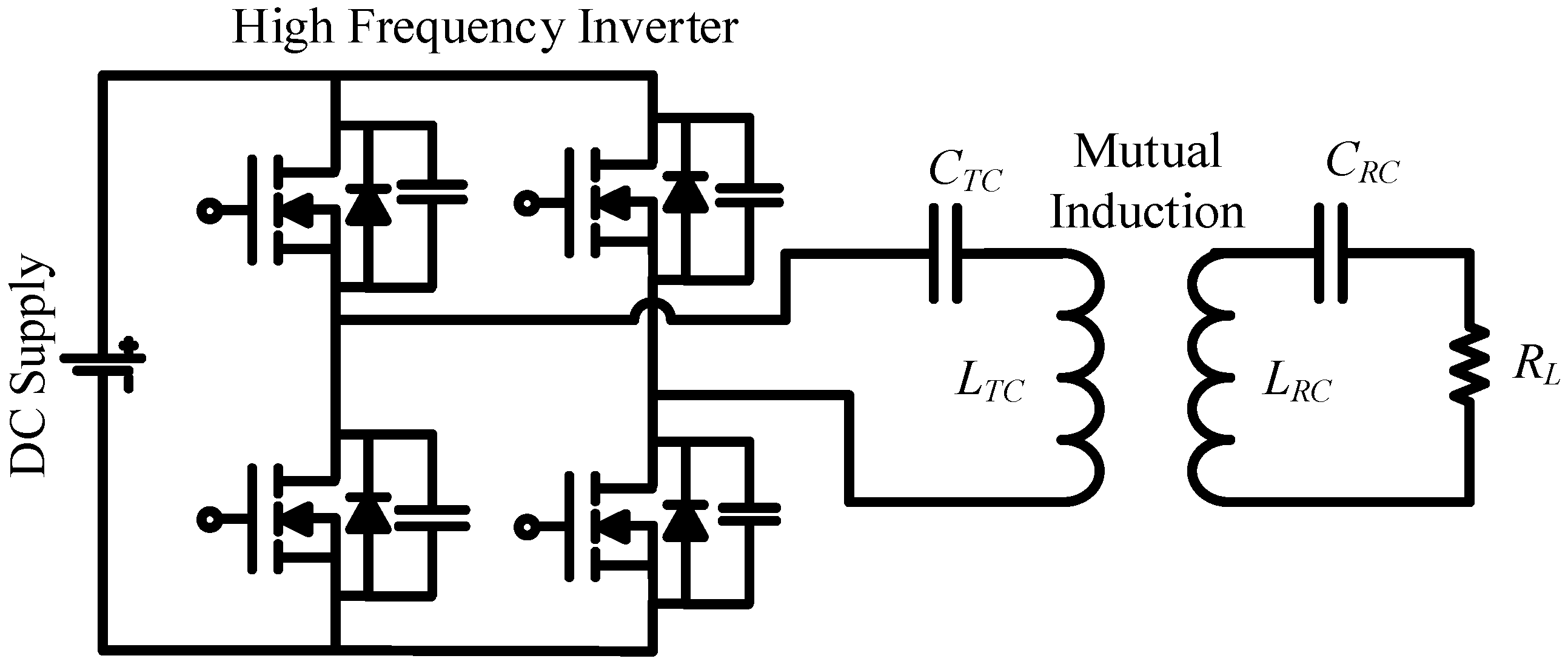
Figure 1 presents the design structure of the proposed air cored coil. As shown in the figure, each coil consists of four small adjoining circular coils surrounded by one large square coil. The diameter of each circular and square coil is 10 cm and 30 cm, respectively. The charging coil and the pick-up coil have identical dimensions and number of turns. For inductance analysis in JMAG software, the geometry editor tool enables the drawing of both identical coils of dimension, i.e., 30 cm × 30 cm, square coil with circular coils inscribed in it, at an air gap of 15 cm between them. Once the geometry of coils is given a shape, the coil material and FEM (finite element method) boundary conditions are defined. The circuits of both coils are linked to their respective geometry. For the analysis of self-inductances and mutual inductance, the charging coil is fed with a constant current source feeding 1 A, and the resistive load of 1 Ω is connected on the pick-up side. The parameters are calculated using real and imaginary parts of respective current and voltages of the coils.
The energy transfer from charging coil (Tc) to pick up coil (Rc) changes with the position and shape of the coils. The coils of any shape, having a complex geometry with a current source, generate electromagnetic fields that can be assessed by considering the contributions of each basic part of the coil. A uniform current distribution is presumed in each small part of the coil [21]. Both of the coil geometries, i.e., square and circular, are accounted in the power transfer from the charging coil to the pick-up coil.
On both the charging and pick-up sides, the circular and square coils are connected in series magnetically and in parallel electrically. Since each coil on both sides share the same terminal, i.e., their dot (.) connection; thus, the polarity of mutual voltage becomes additive. The circular coil forms magnetic flux loops like an arc; however, the square coil makes a magnetic flux loop of the toroidal form [22].
To simplify the expression for evaluation of both the charging and pick-up side coils, we focus on one circular and one square geometry coil. To evaluate the magnetic field across the circular shape geometry shown in Figure 2, it is possible to assume them with homocentric circular geometry for fundamental analysis.
The induced voltage in the whole pick-up coil can be calculated by using Faraday’s law as the sum of induced (electromotive force) EMF of all homocentric loops. Thus, the pick-up coil (RC) with n number of homocentric loops with different radii can be evaluated. The same approach will be applied to charging coil (TC).
The geometry of the square shape is shown in Figure 3. The performance of the square geometry coil is entirely different from the circular coil when considered for near-field application. Each turn of the square coil is a homocentric loop, which is divided into four magnetic poles, i.e., dl1, dl2, dl3 and dl4 as shown in Figure 3. The turns are with different lengths for both the charging and pick-up sides.
Applying Ampere’s law across the charging coil (Tc), the magnetic field strength at the pick-up coil may be found as:
H = I T C 4 π d l × r r 3
The magnetic field intensity (H) is obvious here and depends on the shape of charging coil and the location, size, and shape of the pick-up coil. The voltage induced across the pick-up coil can be found by applying Faraday’s law as the rate of change the flux B over the effective surface area S:
V i = t B d S
Equation (2) can be expressed as
V i = μ o A R C j ω H
where A R C is the active area of the pick-up coil, and µo is the permeability of the free space. A constant magnetic flux intercepting over the active area of the pick-up coil is required by Faraday’s law (3) to be valid.
We proceed here for calculation of magnetic field in the centre of single circular and square coil from charging and pick-up sides. The misaligned positions of circular and square coils have been shown in Figure 2 and Figure 3, respectively. The evaluation of magnetic coupling includes the calculation of the induced voltage across circular and square geometries of the pick-up coil (RC) with the use of Equation (3) and field strength generated by circular and square geometry on charging coil (TC) by using Equation (1).
For the circular charging coil, the element of magnetic field intensity can be computed as:
H = I T C 4 π i = 1 n a i 2 2 ( a i 2 + D 2 ) 3 2
where i is the radial length of a circular coil of the charging side (TC). The total EMF induced across the pick-up coil can be determined by the addition of discrete contributions of each homocentric loop provided by (3):
V i = j μ o ω H . j = 1 k π b j 2
where j is the radial length of a circular coil of the pick-up side. Subsequently, the efficiency includes the coupling between circular coils can be represented as the following:
η C = μ o π 2 ω 2 16 R T C R R C . [ i = 1 n a i 2 ( a i 2 + D 2 ) 3 ] 2 . [ j = 1 k b j 2 ] 2
With the same approach, the efficiency for a set of loosely coupled square spiral coils is provided by expression:
η S = μ o ω 2 A R C 2 64 π 2 R T C R R C . [ i = 1 n 2 a i 2 ( a 2 4 + D 2 ) a 2 2 + D 2 ] 2
Here, i is the magnetic length per pole of charging coil and A R C in Equation (7) is the active area of the square coil of the pick-up coil, and it can be derived as the accumulation of the field of every succeeding turn of the coil and calculated as:
A = 1 3 s 2 N ( N 1 ) ( 2 N 1 ) + d i n 2 2 N + d i n s N ( N 1 )
where N is the number of turns, din is the internal span of the square coil, and s is the distance concerning each consecutive turn.
The Equations (1)–(8) help in determining the efficiency of power transfer from coil to coil. However, to calculate the efficiency of Inductive Power Transfer (IPT) system, the circuit includes resonant component IPT circuit components on charging and the pick-up side and the load resistor connected to the pick-up coil. A T-equivalent circuit of IPT system is drawn in Figure 4. L T C and L R C are the self-inductances of the charging and pick-up side coils, respectively, and M is mutual inductance. C T C and C R C are the compensating capacitances of the charging and pick-up side coils. R1 and R2 are the internal resistances of the charging and pick-up coils respectively and RL is the load resistance.
The coupling coefficient (k), that defines the extent of coupling of the charging and pick-up side coils, is given by:
k = M L T C L R C
The total impedance of the equivalent circuit for given parameters can be calculated as:
Z S S = ( R 1 + j ( L T C ω 1 C T C ω ) ) + ( ω 2 M 2 R 2 + j ( L R C ω 1 C R C ω ) + R L )
The current absorbed from the supply is given by:
I 1 = V s Z S S
I 1 = V s ( R 1 + j ( L T C ω 1 C T C ω ) ) + ( ω 2 M 2 R 2 + j ( L R C ω 1 C R C ω ) + R L )
Now, the circuit is operating at a resonant frequency f and the LC components cancel out their reactance and I1 is given by:
I 1 = V s R 1 + ( ( 2 π f ) 2 M 2 R 2 + R L )
The input power can be calculated as:
P I N = V s 2 R 1 + ( ( 2 π f ) 2 M 2 R 2 + R L )
or:
P I N = V s 2   ( R 2 R L ) R 1 R 2 + R 1 R L + ( 2 π f ) 2 M 2
Likewise, the output power can be obtained as below:
P O U T = V s 2   ( 2 π f ) 2 M 2 R L ( R 1 R 2 + R 1 R L + ( 2 π f ) 2 M 2 ) 2
and the efficiency of the system can be represented by the following equation:
η = P O U T P I N
or
η = R L R L + R 1 ( ( R 2 + R L ) / ( 2 π f M ) ) 2 + R 2

3. System Overview

The capacitors are connected to both charging and pick-up side coils to compensate for the effect of leakage flux. The arrangement of capacitor connection makes four topologies—series-series (SS), series-parallel (SP), parallel-series (PS) and parallel-parallel (PP). The selection of the topologies depends upon their suitability for specific applications satisfying the respective requirements, as SS and SP topologies can transfer higher power than the rated, but these offer an uncertain behavior to the supply [23], and the PS and the PP compensated IPT systems are safe for the supply in the absence of pick-up coil, but these are unable to transfer the rated power if the coils are somewhat misaligned. The characteristics of these configurations are summarized in Table 1, which helps in selecting one them for specific application.
To validate the proposed coil design, a prototype of series-series (SS) compensated IPT system using QDQ coils is developed as shown in Figure 5. There are two prominent advantages of SS topology of IPT system. The reflected impedance of pick-up coil to the charging coil does not constitute the imaginary part. It quantifies that it will draw active power when operated at the resonance frequency and maintain unity power factor. The other advantage is the pick-up coil compensation is independent of resistive load and mutual inductance. According to [16,24], the SS topology is considered as the most suitable for EV charging because the pick-up coil side capacitance is unimpeded from both the magnetic coupling coefficient and the load. It may also act as a constant current and voltage source that is desirable for battery charging [25].
A small figure showing the misaligned position of the coils is also embedded in Figure 5 and marked as “Position B”. The schematic circuit diagram of the experimental set-up is shown in Figure 6. The DC power from the supply is converted to high-frequency AC power with a high-frequency inverter that uses dSPACE (DS1104, dSPACE GmbH, Paderborn, Germany) for high-frequency switching. The high-frequency AC is fed to the compensating capacitor and IPT coils. A resistive load is connected to the receiving side. The SS compensated topology is selected for testing, as it has constant voltage characteristics and that is suitable for charging of EV. To establish the resonance phenomena across coils with their respective capacitances, the resonant frequency f (ωo) has to be maintained [26].
The proposed coil design consists of 10 turns of enameled Litz wire with 0.125 mm strand diameter for each circular and square coil for both charging and pick-up side. The Litz wire is selected to avoid the losses due to the skin effect, as the system circuit will be operated at high frequency. The parameters details are given in Table 2. All of the inductive parameters of charging coil and pick-up coil are measured with PINTEK-900 LCR meter (LCR-900, PINTEK ELECTRONICS CO., LTD, New Taipei City, Taiwan) and verified with accurate values calculated from JMAG software.
During the operation of the IPT system, the voltage across capacitors and coils, in series LC circuit, can be significantly greater than supply voltage, and this is termed as “resonant rise in voltage”. The selected air cored coils can sustain the assigned voltage; however, the capacitors need to be carefully selected to achieve accurate value of capacitance and sustain the assigned voltage level. For resonant frequency operation, the capacitor chosen for the charging coil side is 0.5 µF, and, for the pick-up side coil, is 0.75 µF. The rating of capacitors and their arrangement of connections is done carefully keeping in view the resonant rise in voltage, and, thus, these can sustain the voltage stress. The detailed information of selected power switches and resonant capacitors used in the experimental verification are in Table 3. The series arrangement of the selected capacitor on charging coil and pick-up coil sides enables to acquire desired capacitance and also reduced voltage stress.

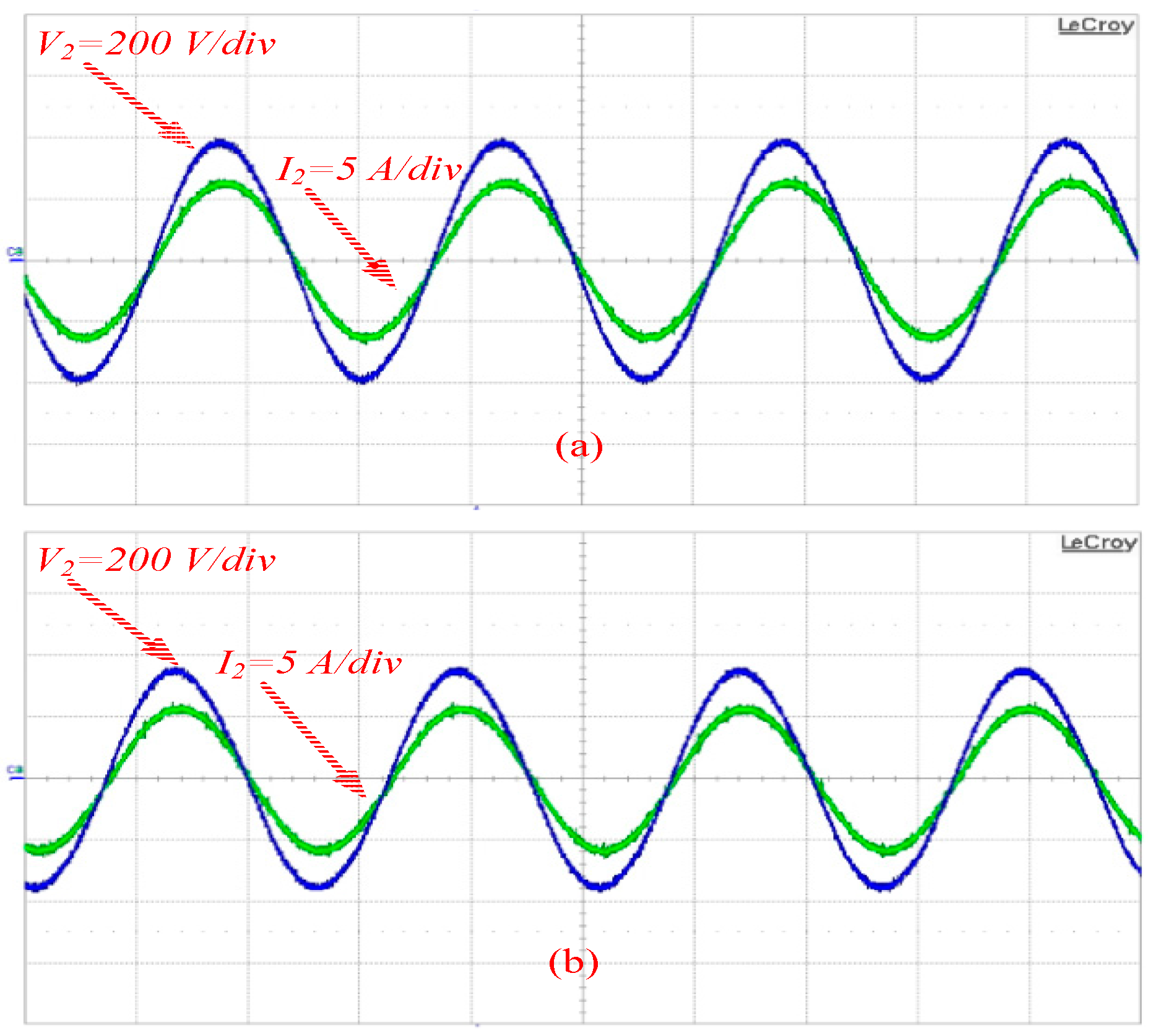
4. Experimental Results

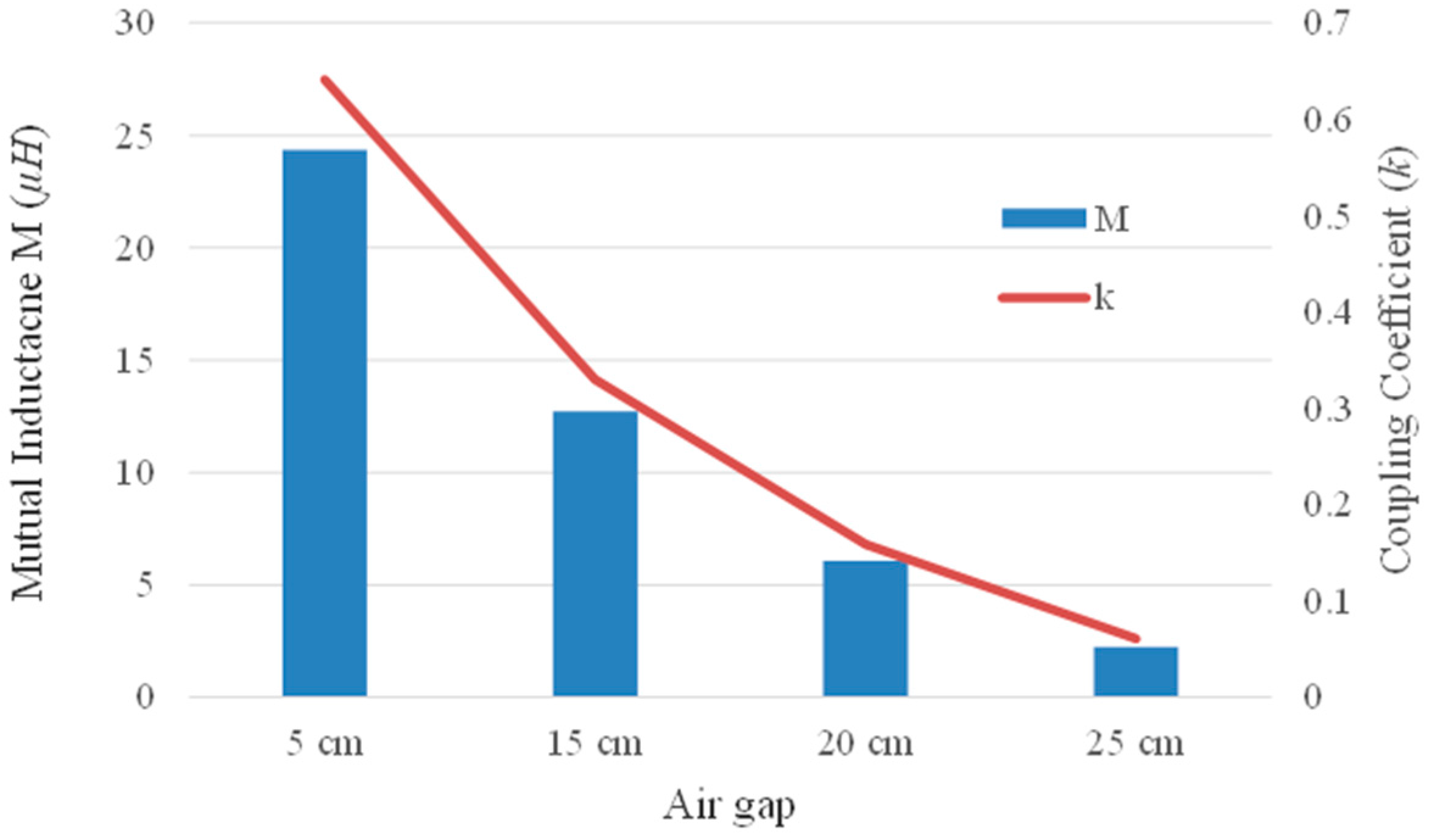
4.1. Coupling Coefficient

The effect of coupling coefficient variance has significant role for the charging of electric vehicles. The design of coils makes a valued coupling between the coils and results promising performance of the IPT system. In the proposed coil design setup, the coils are arranged in such a way that these can be moved in back and forth directions as well as to the left and right sides. The coupling coefficient is measured at different air gaps and is plotted along with measured mutual inductance between charging coil and pick-up coil as shown in Figure 7. The turns of coils are fixed in proper proportion having slight inter-turn gaps, and it helps to create larger active areas of the coil. The slight gap in inter-turns of the coils increases their coupling coefficient, and subsequently their inductances [27].

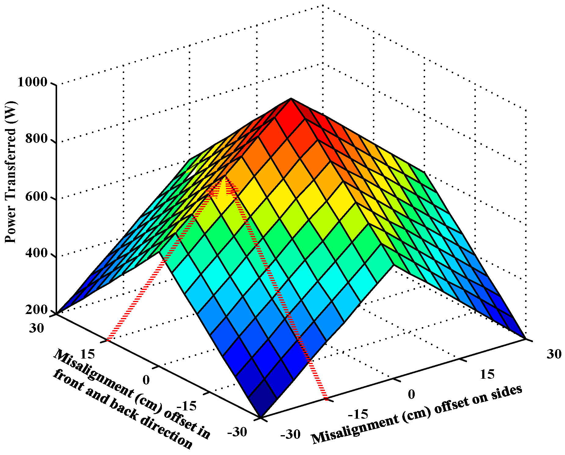
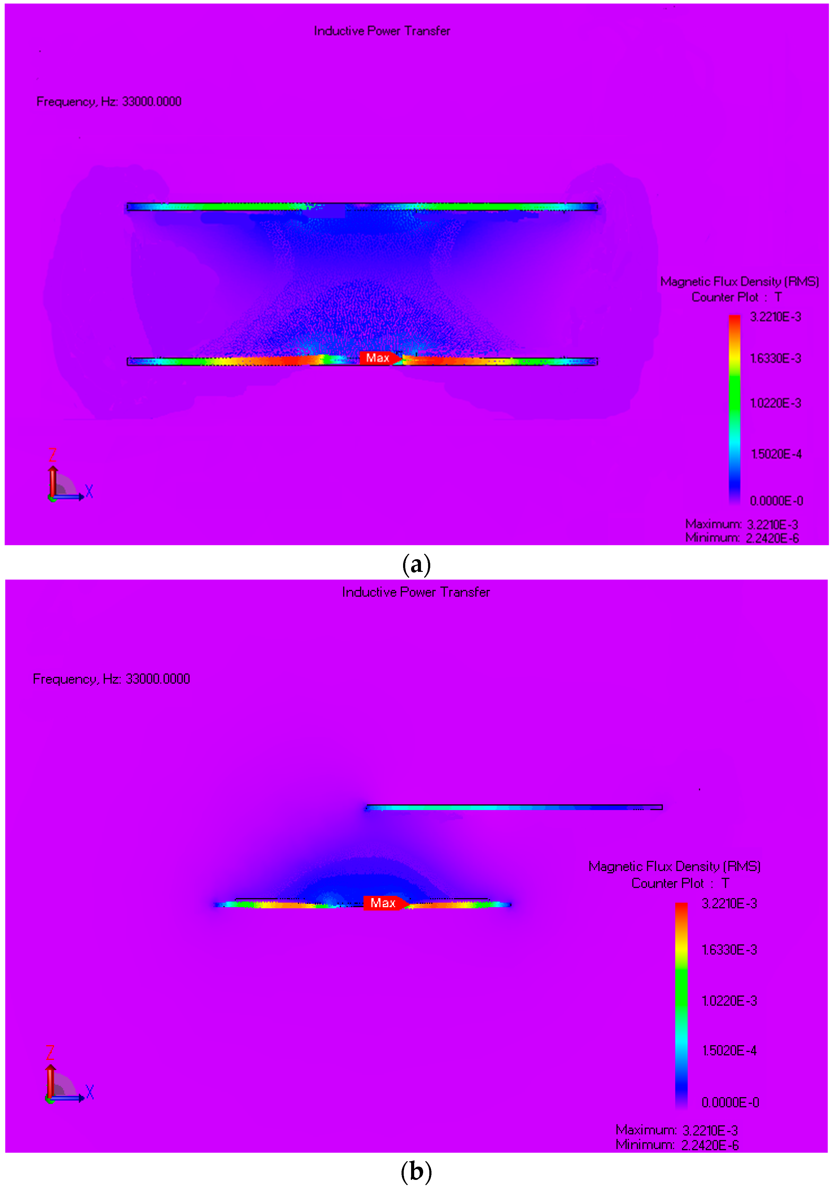
4.2. Misalignment Tolerance Analysis

Misalignment is the displacement of the pick-up coil with respect to the charging coil that leads to a decline in both the efficiency and power transfer of the IPT system. The IPT system for EV charging requires maximum alignment between the coils to avoid inefficient power transfer due to driver mistake while parking the vehicle at the desired position [28]. The car weight may slightly change the air gap between the EV chassis and the ground, and, thereby, coupling; consequently, it would affect the power transfer efficiency [29]. The IPT charging system with perfect alignment will reduce the leakage flux, and, as a result, it reduces the electromagnetic interference emission from the system; however, an IPT system that could offer good tolerance for misalignment to give maximum freedom to the driver, is desirable [16].
To resolve the misalignment issue, the researchers have proposed control method to tune the IPT coils at the resonance frequency [30,31]. However, this method requires additional electronic components and complex control. In [32], the addition of supplementary coils on both charging and pick-up sides has been considered to reduce the effect of misalignment to a certain limit. However, this requires a large area because of extra coils, hence is not suitable for EV charging application. In addition, it increases the cost and weight of the IPT system.
The prototype of the proposed design has been tested at various positions of coils and power level is set to 700 watts. During misalignment tests, the air gap is fixed to 15 cm, and the pick-up coil is moved in back and forth direction until 30 cm, which is also the length of the coil. Likewise, the pick-up coil is moved in the left and right directions until 30 cm offset. It can be observed from Figure 8 at the centered position, i.e., 0 cm is the power transfer high and begins to decline in both directions at the same rate as the dimensions of the coils are square and identical. The coil maintains excellent efficiency until 15 cm displacement in either direction. The system exhibits an efficiency of 91.8% at 0 cm offset and 78% efficiency at 15 cm offset; the arrows in Figure 8 pointing the power transferred at 15 cm misalignment. At 100% misalignment offset, the efficiency of the IPT system drops drastically. With proposed coil design, the misalignment tolerance is extended to 50% of the coil size and can be considered as a significant improvement [33,34]. There has been work on different designs of coils for the IPT system in which magnetic coupling is sensitive to the position of coils with respect to each other [35,36]. In this proposed IPT system, frequency remains fixed to 33 kHz for all the tests conducted for misaligned positions. The QDQ design of the coil enables maintaining high coupling even when the coils are misaligned to 50% of their sizes, thus it helps to transfer the power. In addition, the SS compensated IPT system is selected, and operating frequency in this topology is not mainly contingent on the coupling coefficient.
The output voltage and current at resistive load are recorded with a power analyser when the coils have zero offset and also when the coils are misaligned to 50% of their size. Figure 9a presents the output current and voltage waveforms of the IPT system with 15 cm air gaps at different misaligned positions of the coils. The difference in the output current and voltage waveforms in Figure 9b is evident and is recorded under 50% misaligned position of the coils. In addition, the efficiency of the IPT system drops from 91.4% to 78% when the coils are misaligned.
It is important to follow the electromagnetic compliance described by safety regulation authorities. The reference value of the magnetic field, for operating frequencies of 1 Hz–100 kHz, for general public exposure is set by the International Committee on Non-Ionizing Radiation Protection (ICNIRP) to 27 µT [37,38]. In this research, to avoid the effects of the magnetic field, a tesla meter (ME 3830B) has been used to check the magnetic field intensity in the vicinity. The maximum magnetic field is recorded in the centre of the air gap between coils, i.e., 247 nT; thus, the magnetic field around the prototype can be considered as safe and lies within the limits prescribed by safety regulation authorities for wireless charging.
The magnetic flux density across the charging coil and the pick-up coil are shown in Figure 10. It is evident from Figure 10a, representing the perfect alignment of the coils, that the magnetic field captured across the pick-up coil is high. However, when the coils are moved horizontally from each other as shown in Figure 10b, the field captured by the pick-up coil reduces. As a result, the power received at the pick-up coil gets reduced.

5. Conclusions

A Quad D Quadrature (QDQ) coil design has been proposed to cope with the misalignment toleration concern of the IPT system for the application of electric vehicles. The analytical evaluation of the magnetic field of circular and square geometry coil has been added. The coil design has shown the capability to capture maximum magnetic coupling at different positions of coils. It uses the resultant magnetic field developed from each of four adjacent circular coils and one square coil on both the charging and pick-up sides. The inductive parameters of the coils have been evaluated through FEM in JMAG software and validated with practically measured values. An IPT system prototype has been tested for misalignment tolerance until a 30 cm offset, and the proposed coil design has shown the capability to overcome the issue. The IPT system exhibits a maximum efficiency of 91.4% at the perfectly aligned position of the coils and also maintains an efficiency of 78% at 50% misaligned position of coils. The reported findings encourage the consideration of the proposed design for commercialized EV charging.

Acknowledgments

This work was supported by the High Impact Research of the University of Malaya—Ministry of Higher Education of Malaysia under Project UM.C/HIR/MOHE/ENG/24 and PPP research grant No. PG192-2015B.

Author Contributions

Kafeel Ahmed Kalwar has contributed to the theoretical approaches, simulation, experimental tests, and preparing the article; Saad Mekhilef has contributed to the theoretical approaches, simulations, experimental tests, and preparing the article; Mehdi Seyedmahmoudian has contributed to the theoretical approaches and preparing the article; Ben Horan has contributed to the theoretical approaches and preparing the article.

Conflicts of Interest

The authors declare no conflict of interest.

References

  1. Boys, J.T.; Elliott, G.A.; Covic, G.A. An appropriate magnetic coupling coefficient for the design and comparison of icpt pick-ups. IEEE Trans. Power Electron. 2007, 22, 333–335. [Google Scholar] [CrossRef]
  2. Madawala, U.K.; Thrimawithana, D.J. A bidirectional inductive power interface for electric vehicles in V2G systems. IEEE Trans. Ind. Electron. 2011, 58, 4789–4796. [Google Scholar] [CrossRef]
  3. Del Toro García, X.; Vázquez, J.; Roncero-Sánchez, P. Design, implementation issues and performance of an inductive power transfer system for electric vehicle chargers with series-series compensation. IET Power Electron. 2015, 8, 1920–1930. [Google Scholar] [CrossRef]
  4. Keeling, N.A.; Covic, G.A.; Boys, J.T. A unity-power-factor IPT pick-up for high-power applications. IEEE Trans. Ind. Electron. 2010, 57, 744–751. [Google Scholar] [CrossRef]
  5. Sallan, J.; Villa, J.L.; Llombart, A.; Sanz, J.F. Optimal design of ICPT systems applied to electric vehicle battery charge. IEEE Trans. Ind. Electron. 2009, 56, 2140–2149. [Google Scholar] [CrossRef]
  6. Yuan, X.F.; Zhang, Y.L.; Wang, Y.; Li, Z.Q. Output voltage control of inductive power transfer system based on extremum seeking control. IET Power Electron. 2015, 8, 2290–2298. [Google Scholar] [CrossRef]
  7. Duan, C.; Jiang, C.; Taylor, A.; Bai, K. Design of a zero-voltage-switching large-air-gap wireless charger with low electric stress for electric vehicles. IET Power Electron. 2013, 6, 1742–1750. [Google Scholar] [CrossRef]
  8. Liao, Y.H.; Yuan, X.Q. Compensation topology for flat spiral coil inductive power transfer systems. IET Power Electron. 2015, 8, 1893–1901. [Google Scholar] [CrossRef]
  9. Zheng, C.; Ma, H.B.; Lai, J.S.; Zhang, L.H. Design considerations to reduce gap variation and misalignment effects for the inductive power transfer system. IEEE Trans. Power Electron. 2015, 30, 6108–6119. [Google Scholar] [CrossRef]
  10. Elliott, G.A.J.; Raabe, S.; Covic, G.A.; Boys, J.T. Multiphase pick-ups for large lateral tolerance contactless power-transfer systems. IEEE Trans. Ind. Electron. 2010, 57, 1590–1598. [Google Scholar] [CrossRef]
  11. Kurschner, D.; Rathge, C.; Jumar, U. Design methodology for high efficient inductive power transfer systems with high coil positioning flexibility. IEEE Trans. Ind. Electron. 2013, 60, 372–381. [Google Scholar] [CrossRef]
  12. Hsu, J.U.W.; Hu, A.P.; Swain, A. Fuzzy logic-based directional full-range tuning control of wireless power pick-ups. IET Power Electron. 2012, 5, 773–781. [Google Scholar] [CrossRef]
  13. Liu, X.C.; Wang, G.F.; Ding, W. Efficient circuit modelling of wireless power transfer to multiple devices. IET Power Electron. 2014, 7, 3017–3022. [Google Scholar] [CrossRef]
  14. Moradewicz, A.J.; Kazmierkowski, M.P. Contactless energy transfer system with FPGA-controlled resonant converter. IEEE Trans. Ind. Electron. 2010, 57, 3181–3190. [Google Scholar] [CrossRef]
  15. Liu, N.; Habetler, T. Design of a universal inductive charger for multiple electric vehicle models. IEEE Trans. Power Electron. 2015, 30, 6378–6390. [Google Scholar] [CrossRef]
  16. Wang, C.S.; Stielau, O.H.; Covic, G.A. Design considerations for a contactless electric vehicle battery charger. IEEE Trans. Ind. Electron. 2005, 52, 1308–1314. [Google Scholar] [CrossRef]
  17. Grover, F.W. Inductance Calculations: Working Formulas and Tables; Courier Corporation: North Chelmsford, MA, USA, 2004. [Google Scholar]
  18. Mecke, R.; Rathge, C. High Frequency Resonant Inverter for Contactless Energy Transmission over Large Air Gap. In Proceedings of the IEEE 35th Annual ower Electronics Specialists Conference (PESC), Aachen, Germany, 20–25 June 2004.
  19. Budhia, M.; Covic, G.A.; Boys, J.T. Design and optimization of circular magnetic structures for lumped inductive power transfer systems. IEEE Trans. Power Electron. 2011, 26, 3096–3108. [Google Scholar] [CrossRef]
  20. Budhia, M.; Boys, J.T.; Covic, G.A.; Huang, C.Y. Development of a single-sided flux magnetic coupler for electric vehicle IPT charging systems. IEEE Trans. Ind. Electron. 2013, 60, 318–328. [Google Scholar] [CrossRef]
  21. Urankar, L.K. Vector potential and magnetic field of current-carrying finite ARC segment in analytical form, part I: Filament approximation. IEEE Trans. Magn. 1980, 16, 1283–1288. [Google Scholar] [CrossRef]
  22. Kaneko, Y.; Abe, S. Technology trends of wireless power transfer systems for electric vehicle and plug-in hybrid electric vehicle. In Proceedings of the IEEE 10th International Conference on Power Electronics and Drive Systems, Kitakyushu, Japan, 22–25 April 2013.
  23. Villa, J.L.; Sallan, J.; Sanz Osorio, J.F.; Llombart, A. High-misalignment tolerant compensation topology for ICPT systems. IEEE Trans. Ind. Electron. 2012, 59, 945–951. [Google Scholar] [CrossRef]
  24. Throngnumchai, K.; Kai, T.; Minagawa, Y. A Study on Receiver Circuit Topology of a Cordless Battery Charger for Electric Vehicles. In Proceedings of the IEEE Energy Conversion Congress and Exposition (ECCE), Phoenix, AZ, USA, 17–22 September 2011.
  25. Yilmaz, M.; Krein, P.T. Review of battery charger topologies, charging power levels, and infrastructure for plug-in electric and hybrid vehicles. IEEE Trans. Power Electron. 2013, 28, 2151–2169. [Google Scholar] [CrossRef]
  26. Bhuyan, S.; Sivanand, K.; Panda, S.K.; Kumar, R.; Hu, J. Resonance-based wireless energizing of piezoelectric components. IEEE Magn. Lett. 2011, 2, 6000204. [Google Scholar] [CrossRef]
  27. Mohan, S.S.; Hershenson, M.D.; Boyd, S.P.; Lee, T.H. Simple accurate expressions for planar spiral inductances. IEEE J. Solid-State Circuits 1999, 34, 1419–1424. [Google Scholar] [CrossRef]
  28. Budhia, M.; Covic, G.A.; Boys, J.T. Design and optimisation of magnetic structures for lumped inductive power transfer systems. In Proceedings of the IEEE Energy Conversion Congress and Exposition, San Jose, CA, USA, 20–24 September 2009.
  29. Chigira, M.; Nagatsuka, Y.; Kaneko, Y.; Abe, S.; Yasuda, T.; Suzuki, A. Small-size light-weight transformer with new core structure for contactless electric vehicle power transfer system. In Proceedings of the IEEE Energy Conversion Congress and Exposition (ECCE), Phoenix, AZ, USA, 17–22 September 2011.
  30. Si, P.; Hu, A.P.; Malpas, S.; Budgett, D. A frequency control method for regulating wireless power to implantable devices. IEEE Trans. Biomed. Circuits Syst. 2008, 2, 22–29. [Google Scholar] [CrossRef] [PubMed]
  31. Madawala, U.K.; Neath, M.; Thrimawithana, D.J. A power-frequency controller for bidirectional inductive power transfer systems. IEEE Trans. Ind. Electron. 2013, 60, 310–317. [Google Scholar] [CrossRef]
  32. Kamineni, A.; Covic, G.; Boys, J.T. Analysis of co-planar intermediate coil structures in inductive power transfer systems. In Proceedings of the IEEE Energy Conversion Congress and Exposition (ECCE), Pittsburgh, PA, USA, 14–18 September 2014.
  33. Zhu, Q.W.; Guo, Y.J.; Wang, L.F.; Liao, C.L.; Li, F. Improving the misalignment tolerance of wireless charging system by optimizing the compensate capacitor. IEEE Trans. Ind. Electron. 2015, 62, 4832–4836. [Google Scholar] [CrossRef]
  34. Zhang, W.; White, J.C.; Abraham, A.M.; Mi, C.C. Loosely coupled transformer structure and interoperability study for EV wireless charging systems. IEEE Trans. Power Electron. 2015, 30, 6356–6367. [Google Scholar] [CrossRef]
  35. Boys, J.; Covic, G.; Green, A.W. Stability and control of inductively coupled power transfer systems. IEE Proc. Electr. Power Appl. 2000, 147, 37–43. [Google Scholar] [CrossRef]
  36. Gao, Y.; Farley, K.B.; Tse, Z.T.H. A uniform voltage gain control for alignment robustness in wireless EV charging. Energies 2015, 8, 8355–8370. [Google Scholar] [CrossRef]
  37. International Commission on Non-Ionizing Radiation Protection. Guidelines for limiting exposure to time-varying electric and magnetic fields (1 Hz to 100 kHz). Health Phys. 2010, 99, 818–836. [Google Scholar]
  38. Wen, F.; Huang, X. Optimal magnetic field shielding method by metallic sheets in wireless power transfer system. Energies 2016, 9, 733. [Google Scholar] [CrossRef]
Figure 1. Quad D Quadrature (QDQ) coil design model in JMAG software (version 14.0, JSOL Corporation, Tokyo, Japan).
Energies 09 00937 g001
Figure 2. Circular coil geometry set.
Energies 09 00937 g002
Figure 3. Square geometry coil set.
Energies 09 00937 g003
Figure 4. T-equivalent circuit of series-series inductive power transfer (IPT) system.
Energies 09 00937 g004
Figure 5. Experimental set-up of the inductive power transfer (IPT) system.
Energies 09 00937 g005
Figure 6. Schematic circuit diagram of experimental inductive power transfer (IPT) system.
Energies 09 00937 g006
Figure 7. Mutual inductance and coupling coefficient of QDQ coils.
Energies 09 00937 g007
Figure 8. Power transferred during misalignment in across side and longitudinal direction.
Energies 09 00937 g008
Figure 9. Output voltage and current (a) at perfect alignment; and (b) at 50% misalignment.
Energies 09 00937 g009
Figure 10. Magnetic Flux density (a) coils are perfect alignment; and (b) coils are misaligned to 50% of their size.
Energies 09 00937 g010
Table 1. Characteristics of compensation topologies.
TopologyPower Factor at Longer DistanceTotal Impedance at Resonant StateSuitability for Power LevelSensitivity to Alignment
Series-Series (SS)Significantly HighLowHigh PowerLess Sensitive
Series-Parallel (SP)HighLowHigh PowerLess Sensitive
Parallel-Series (PS)MediumHighLow PowerSensitive
Parallel-Parallel (PP)MediumHighLow PowerHighly Sensitive
Table 2. Parameters of the inductive power transfer (IPT) system.
SymbolQuantityValue
LTCCharging coil inductance46.46 µH
LRCPick-up coil inductance30.99 µH
MMutual inductance12.27 µH
kCoupling coefficient0.33
fResonant frequency33 kHz
CTCCharging coil compensating capacitance0.5 µF
CRCPick-up coil compensating capacitance0.75 µF
APhysical dimensions of the coil30 cm × 30 cm
Table 3. Selected Electronic components.
ComponentProduct NumberSpecification
MOSFETIPW60R041C6VDSIDfmaxRDS (ON)
650 V44 A100 kHz0.041 Ω
Capacitors105PHC700KNTypeCfmaxVAC
Film1 µF100 kHz380 V
Note: VDS, ID and RDS are drain to source voltage and drain current and drain to source resistance of MOSFET switch respectively.

