1. Introduction
Due to an increased global interest in renewable energy systems and environmental concerns, distributed generators (DGs) are being installed increasingly. The high penetration level of distributed energy resources (DERs) in electric power systems has led to a change in the requirements for ancillary services in local DGs such as islanded operation, interconnection control to the grid, and fault management functions [
1,
2,
3,
4,
5,
6].
Islanded operation is essential for inverter-based DGs in microgrid or uninterruptible power supply (UPS) applications. It requires a local voltage and frequency control function for local DGs, which simple grid-tied inverters do not have [
3,
7,
8]. Moreover, there is a well-known limitation on voltage distortion in islanded DGs and UPS loads, and this has stimulated the development of a variety of different control schemes [
1,
2,
9,
10]. To improve voltage control performance, several high-performance feedback control schemes have been introduced, such as sliding mode control, robust control, model predictive control (MPC), and deadbeat control. A sliding-mode control of single-phase UPS inverters which utilizes a time-varying slope in the sliding surface function was introduced in [
11]. Modern robust control theory based approaches such as
control and
synthesis can systematically handle the possible uncertainties in islanded DG systems [
12,
13]. Thus, these methods can provide good tradeoffs between performance and stability margin. MPC-based methods do not use general modulation mothods to approximate inverter voltages to the desired control input [
14,
15]. Instead, they use a system model to predict and a cost function to select the switching state in every sample step. This control strategy is simple but it requires a very high sampling rate.
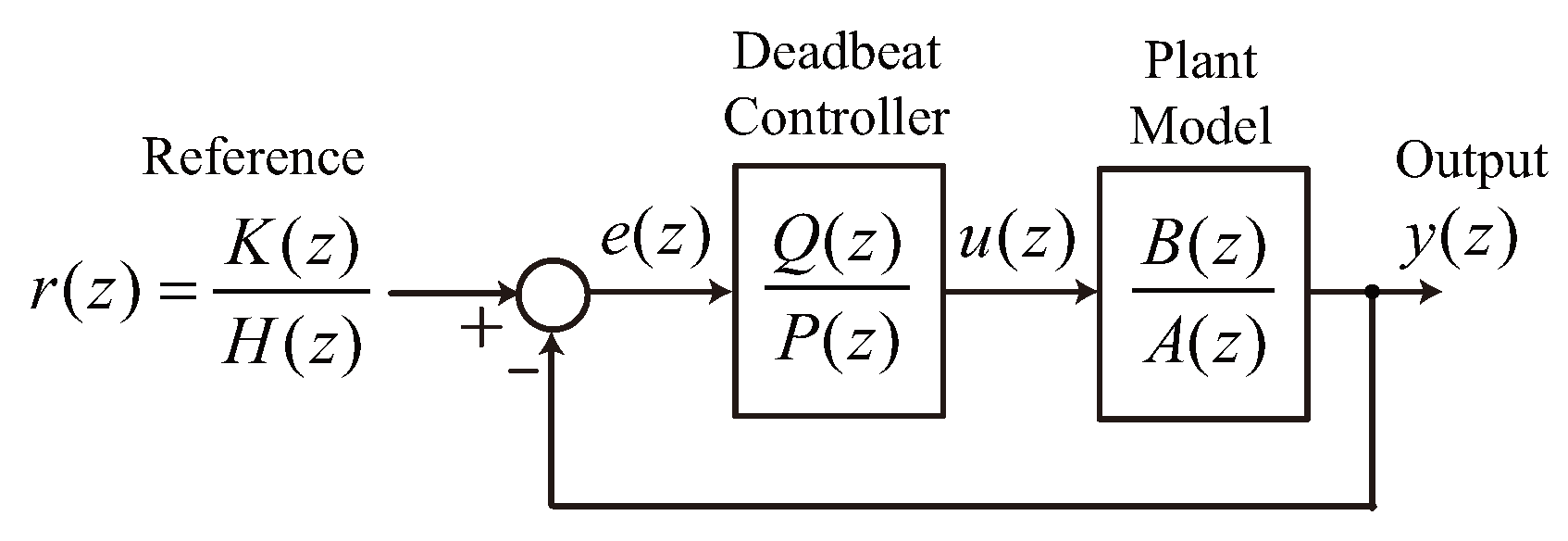
Deadbeat control is one of the most attractive approaches for discrete-time control because it can eliminate errors within a finite number of sampling steps, thus providing the fastest dynamic response in digital implementations. Therefore, deadbeat control schemes have been applied to inverter controls for a sinusoidal output voltage [
5,
16,
17,
18,
19,
20]. The first designs of the deadbeat control were published around 40 years ago but the research is still active. Deadbeat control has been adopted to power electronic based UPS systems after the late 1980s. It was first implemented in a single-phase UPS in [
16] and a cyclic load disturbance was considered in [
17]. A deadbeat control design method in the synchronous dq frame for three-phase inverters was introduced in [
18] and it was utilized in the space vector modulation (SVM) technique in [
19]. In [
10], deadbeat control performance was improved with a cooperative disturbance observer. The disturbance observer was devised to eliminate the effect of unpredictable disturbance and model errors. A deadbeat UPS control method with a one-step-ahead predictor was introduced in [
5]. The predictor compensates one sample step delay caused by the digital processor and thus prevents output oscillations caused by the delay. All the previous deadbeat control laws have derived from the ideal inductor-capacitor (LC) filter model without damping term. Therefore, the resultant stability margin is very small and model error always exists.
Deadbeat control has some drawbacks. First, it is highly sensitive to model parameters and measurement noise, which result in oscillatory output and steady-state offset. To reduce this sensitivity, additional control blocks such as a disturbance observer has been adopted [
10,
21]. In these approaches, the design of the observer plays an important role in reducing the sensitivity of deadbeat control and increasing the stability margin [
5]. However, time-varying disturbances are not handled well by the disturbance estimator. If the disturbance estimator is made fast, performance is increased at the cost of robustness, and the stability limit drops to (typically) 75% parameter error [
22].
The second problem is that deadbeat control is sensitive to inverter computational delay. A digital control loop in a periodic interrupt-driven digital system has a delay of two sampling steps. There is one sampling step for analog-to-digital (A/D) conversion of the feedback signal and another for inverter pulse-width-modulation (PWM) outputs. The delay is manifested by a computational delay and should be compensated; otherwise, oscillations appear [
22]. This delay can be compensated using a famous and simple prediction algorithm called the Smith predictor [
23].
In practical implementations of deadbeat control schemes, the model cannot be perfectly matched. A small mismatch causes pole-zero cancelations of the LC filter-induced poles and deadbeat controller-induced zeros to be impractical. LC resonance then appears in the controlled output. Therefore, LC resonance should be suppressed in a different way. The virtual impedance concept, also called the active damping approach, was introduced in [
4,
24,
25]. This emulated impedance does not induce additional energy loss. The virtual impedance is realized by modifying the PWM reference signals directly, similar to the inner control loop of a multi-loop voltage control scheme [
4]. It adds a controllable variable that improves the stability of local voltage control by damping the LC resonance, thus resulting in better power quality in an inverter-based islanded local power system.
To reduce sensitivity to model error and unpredictable disturbances, a direct deadbeat voltage control design method based on an actively damped plant model is devised in this paper. The LC filter model was derived from practical consideration of parasitic impedances such as on-state resistance of the insulated gate bipolar transistor (IGBT), winding resistance of the filter inductor, and equivalent series resistance (ESR) of the filter capacitor. Based on the analysis, a detailed actively damped LC filter model with a virtual damper is built in
Section 2. The deadbeat control law is derived from the actively damped LC filter model, and the effect of the virtual damper on deadbeat voltage control is studied in
Section 3. The proposed deadbeat voltage control is validated through experimental results in
Section 4.
2. Actively Damped Inductor-Capacitor Plant Model
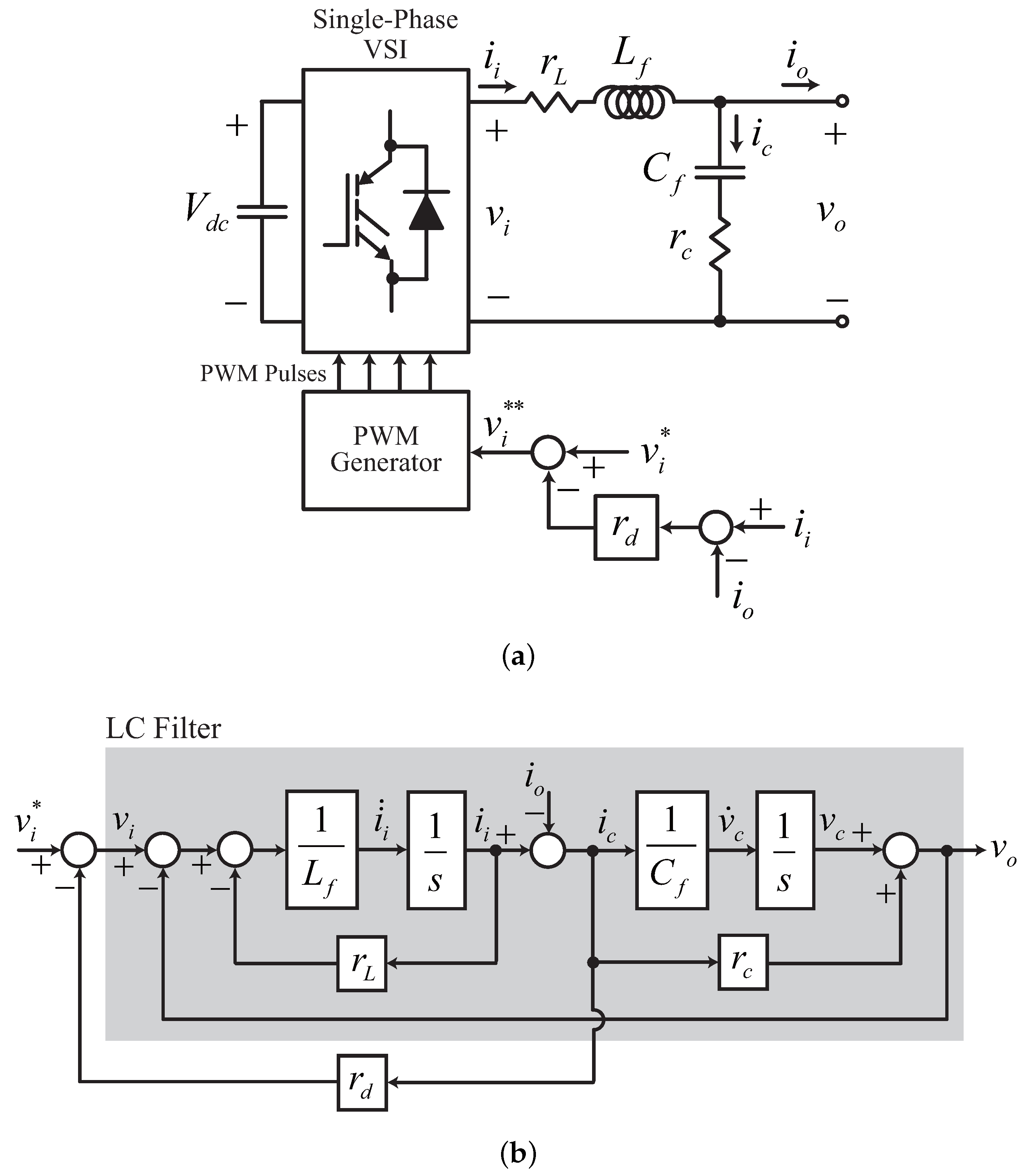
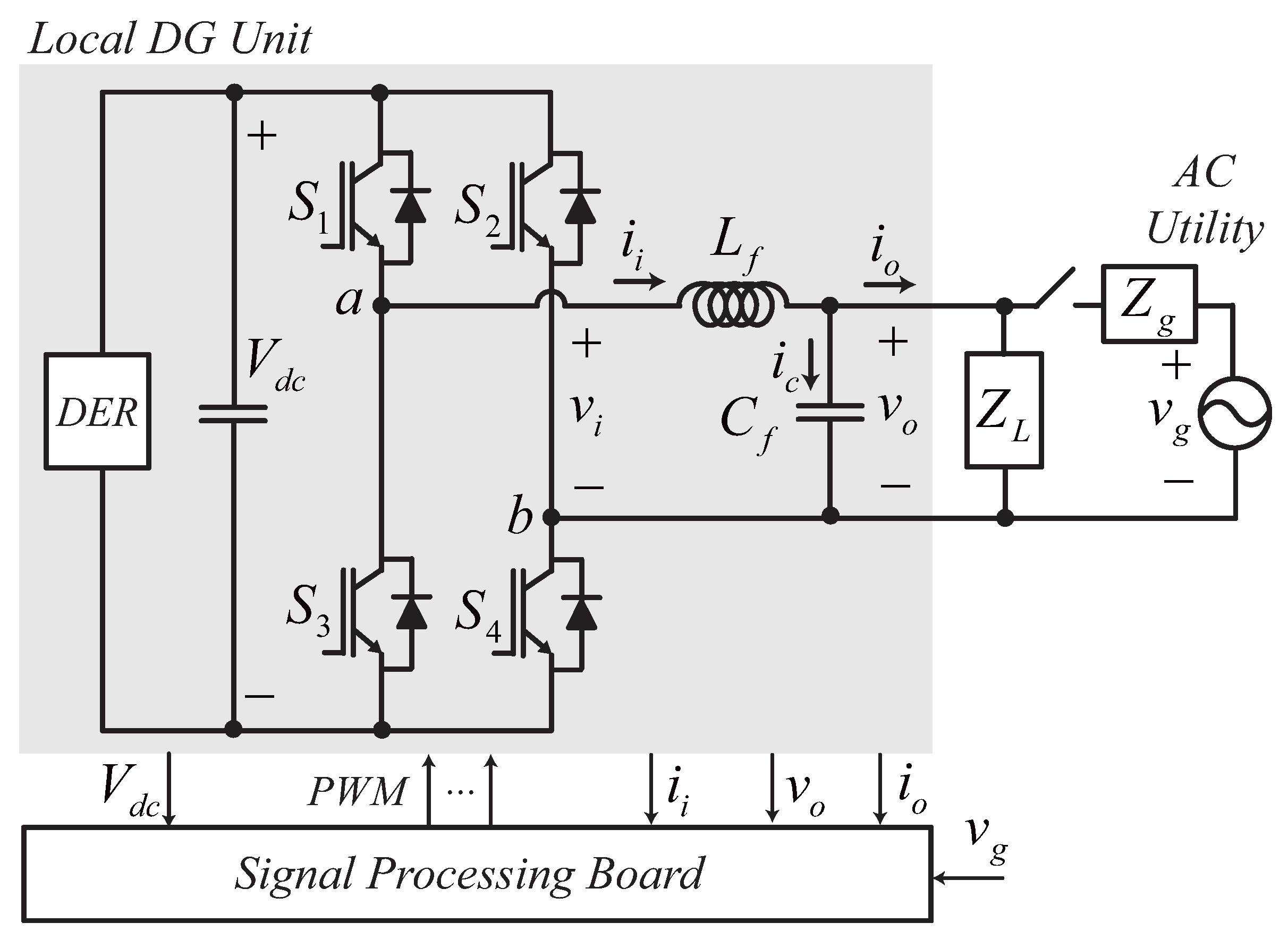
An inverter-based DG system is shown in
Figure 1.
is the filter inductance,
is the filter capacitance,
is the load impedance, and
is the transmission line impedance. The local DG inverter is connected to the local power bus via an LC output filter. The local load is primarily fed by the local DG unit, and the utility grid is a backup power supply in normal operation. The grid switch is normally open. When the local power demand exceeds the generation capacity of the local DG, the grid switch is closed to enable power supply from the grid. However, when the total amount of local power generation consistently exceeds the local power demand, the grid switch is also closed to supply power from the local DG to the grid.
At the output stage of the single-phase DG unit in
Figure 1, inverter output voltage
and load current
are considered as the actuating and disturbance inputs of the LC plant, respectively, and the LC filter output voltage
is the system output to be controlled in islanded operation of the local DG. The plant dynamics between
and
are presented in the form of a second-order resonant tank. However, in practice, the resonance characteristic is alleviated in the LC filter output because of small parasitic impedances of the inverter and the real LC filter circuit. The equivalent circuit of the practical LC filter is shown in
Figure 2a.
is the sum of the equivalent resistances in IGBTs, connectors, and inductor windings, which is generally less than 0.5 Ω.
is the ESR of the capacitor and connectors, which generally is approximately 0.4 Ω for electrolytic AC capacitors. The practical LC filter model is then:
and:
where
is the voltage drop across the ideal filter capacitor. Note from Equation (
1) that two small parasitic resistances,
and
, effectively induce the damping term in the LC filter dynamics and thus cause the resonance peak in a practical LC filter response to be finite.
Active Damping Control with Capacitor Current Feedback
Undesirable LC resonance increases the difficulty of linear control design for the LC filter output voltage. The maximum feasible value of the integral gain in a conventional proportional-integral (PI) type controller for stable operation is limited by the LC resonance and is usually small because the closed-loop poles are located near the imaginary axis, and the integral gain pushes them to the right side of the complex s-plane [
24]. Moreover, the resonance frequency is too high to eliminate the resonance using direct voltage control action because the resonance frequency is normally very close to the voltage control bandwidth. A double-loop voltage control method composed of an inner current and outer voltage control loop is widely used to avoid second-order resonance [
1,
2,
8,
18,
26]. However, in this case, the voltage control bandwidth is limited to prevent control coupling between two cascade controls; thus, voltage control performance is degraded [
27].
To control the LC filter output voltage directly, the second-order resonance should be damped properly before control design [
24]. To increase the damping term in (
1) without additional energy loss, an effective resistance emulation method, so-called active damping control, was introduced in [
24,
25,
28,
29,
30].
Figure 2a shows the resonance damping method utilizing capacitor current feedback. The capacitor current is calculated from the measured inverter current,
and the load current,
; then the virtual resistance,
, is multiplied by the calculated capacitor current to emulate the virtual voltage drop in
. The corresponding equivalent block diagram for an actively damped LC plant is shown in
Figure 2b.
By referring to
Figure 2b, Equation (
1) is changed to:
and the Laplace transform of Equations (
2) and (
3) yields:
where
s denotes the Laplace operator. The virtual damper,
, effectively increases the damping term in Equation (
4). The corresponding frequency domain plots are shown in
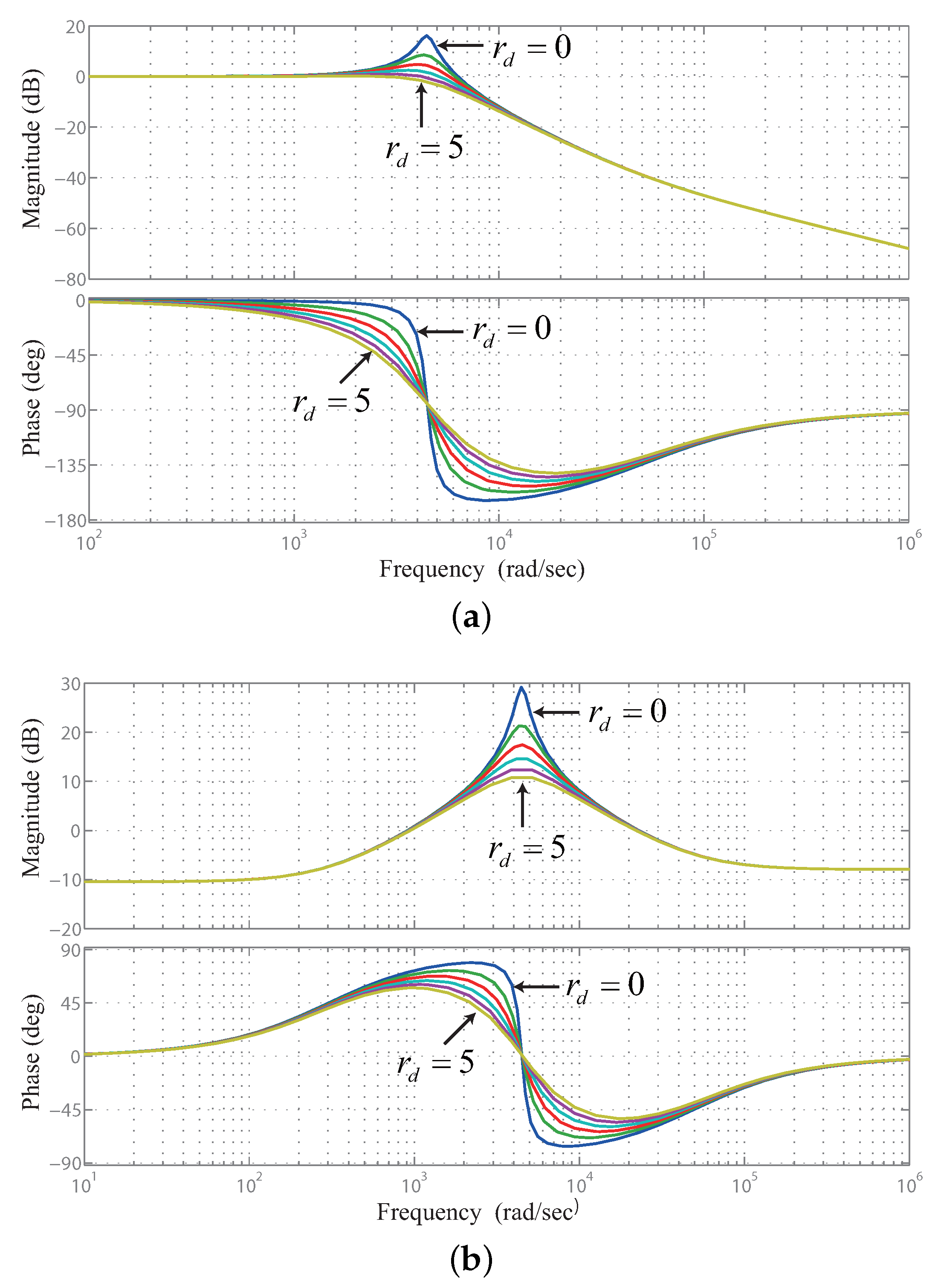
Figure 3.
As
increases, the resonance peak is reduced in the magnitude responses for both the input,
, and the disturbance,
. However, in the phase response, the phase delay for
near the operating frequency (314 rad/s) increases as
increases, whereas the phase lead for
is reduced. Thus, in practice, the maximum value of
is limited by the bandwidth of the LC filter. By letting
, the bandwidth of Equation (
4) is calculated approximately as:
where:
Note from Equation (
5) that the bandwidth for voltage transfer in an LC filter is significantly reduced when the virtual damper
is too large. The magnitude of change in the plant bandwidth with a small
of less than four ohms reduces the plant bandwidth to below 20%, as shown in
Table 1. Slight bandwidth reduction in the plant dynamics is inevitable if a virtual damper is utilized. Therefore, high-performance, fast voltage control is needed to effectively compensate for the phase lag caused by the controlled plant.
3. Ripple-Free Deadbeat Voltage Control Design Based on an Actively Damped Inductor-Capacitor Filter Model
Deadbeat control can reduce errors to zero within a finite number of sampling steps, usually giving the fastest dynamic response for digital implementation [
10,
19,
20]. Ripple-free fast deadbeat digital control was introduced in [
31]. An actively damped LC filter model Equation (
3) is discretized as:
and:
The discrete transfer function of an actively damped LC plant is obtained from the discrete state-space model Equations (
6) and (
7), which is:
where
z and
denote the complex
z-transform operator and the sampling time, respectively. Equation (
8) is the discretized, actively damped LC plant model.
The main idea in this paper is to use Equation (
8) in ripple-free deadbeat control design. By assuming that all poles of Equation (
8) lie inside the unit circle, we obtain control design functions as follows [
31]:
It is assumed that all polynomials in
Figure 4 are coprime polynomials and have stable factors only. Then, with unit-step input:
Because the plant is stable, to minimize the settling time, we make the choice:
where
. From the discretized plant model Equation (
8):
and:
Then, the ripple-free deadbeat controller should then have the form:
which satisfies the Diophantine equation:
for a causal controller. For the minimal-degree solution let
. The resultant second-order deadbeat voltage control law for an actively damped LC filter is calculated as:
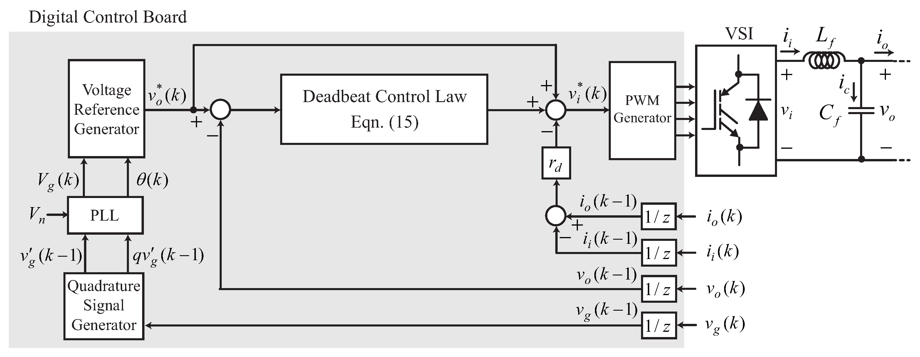
3.1. Overall Voltage Control Structure
The proposed deadbeat voltage control structure is shown in
Figure 5. Four feedbacks are utilized for all modes of DG operation, which are
,
,
, and
.
is used for capacitor current calculation and over-current protection,
is used for inverter output power calculation and disturbance measurement,
is used for local AC bus voltage control, and
is used for grid synchronization in grid-connected mode. The quadrature signal-based phase-locked-loop (PLL) outputs a nominal voltage magnitude reference and a self-generated phase angle in the islanded mode of operation. The feedback compensator is composed of Equation (
15) with reference feed-forward. Deadbeat control action compensates instantaneous errors between the reference and the output in a predictive manner, whereas the reference feed-forward term eliminates the steady phase lag between the continually varying AC voltage reference and the controlled AC output.
Note that the computational delay is not compensated, and the disturbance observer is not utilized in
Figure 5. Simple predictors are often utilized to compensate for the computational delay when the deadbeat control law is applied to power electronic converters [
22,
23]. This can reduce the output oscillations caused by the delays. Because of the predictive nature of deadbeat control, it is vulnerable to the disturbance offset. In a few studies, disturbance observers have been utilized to compensate for the disturbance offset [
21,
30]. In this study, the predictor and disturbance observers are not utilized because the purpose of this study is to analyze exactly the effect of the virtual damper on second-order deadbeat voltage control without any dynamic interactions with predictors or observers.
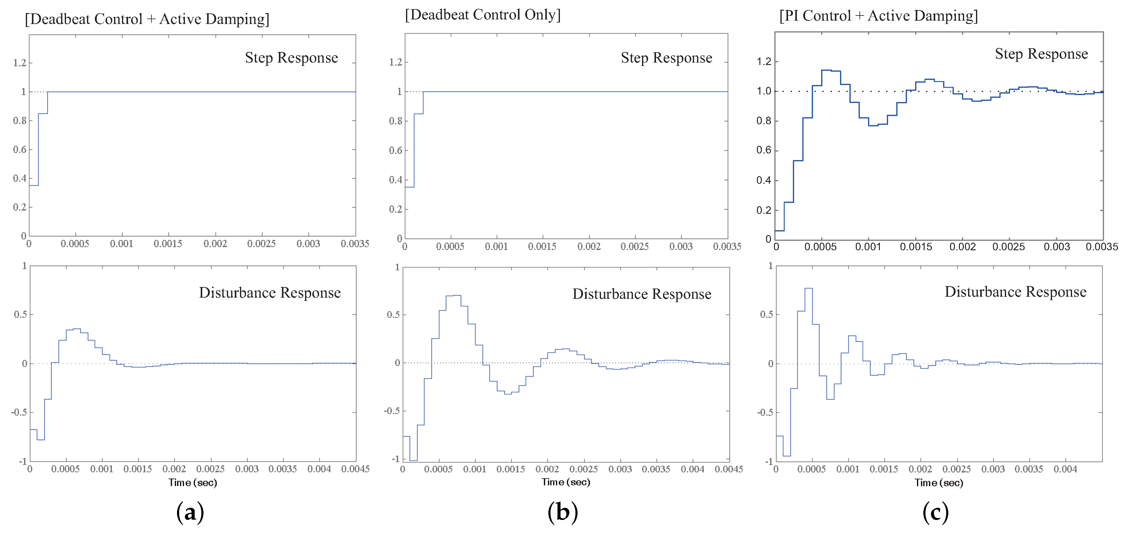
To evaluate the performance of the proposed direct deadbeat voltage control, reference and disturbance responses for the closed-loop system are compared in
Figure 6. For a unit step reference, the output is not affected by the virtual damper for the same deadbeat control. On the other hand, when the unit step disturbance is applied, the proposed direct deadbeat control method not only shortens the transient period but also reduces the magnitude of oscillation drastically, as shown in
Figure 6a.
3.2. Effect of Parameter Mismatches
The main drawback of deadbeat control is that it is sensitive to system parameters. As the parameter mismatch increases, the deadbeat nature diminishes and the stability margin is reduced. To analyze the effect of parameter mismatches, parameter errors are added to the discrete closed-loop system transfer function as:
The loci of the closed-loop poles with respect to the parameter errors are shown in
Figure 7. Two conjugate poles are canceled by two zeros added by the controller, and other poles are at the origin in the perfect match condition. As the parameter mismatch increases, the two conjugate poles turn away from the controller-induced zeros and move outside of the unit circle. The other two poles move away from the origin as the parameter errors increase. The conjugate poles start at closer points to the origin when the virtual damper is applied, as shown in
Figure 7a. Therefore, the virtual damper increases the robustness of deadbeat voltage control against the parameter mismatches.
4. Experimental Results
The proposed deadbeat control has been tested on a laboratory prototype. System parameters are listed in
Table 2. The output filter resonance frequency was approximately 4082 rad/s. The DC link voltage was fixed at 500 V with the assumption that it was controlled by a front DC/DC converter. The nominal voltage and frequency of the local AC bus were set to 220 Vrms and 50 Hz, respectively.
Two electrical loads were built up: inductive and nonlinear. The severe nonlinear load is composed of a diode rectifier, inductor, and resistor. The DC load resistance was 33 Ω, comprising a 3-kW nonlinear load.
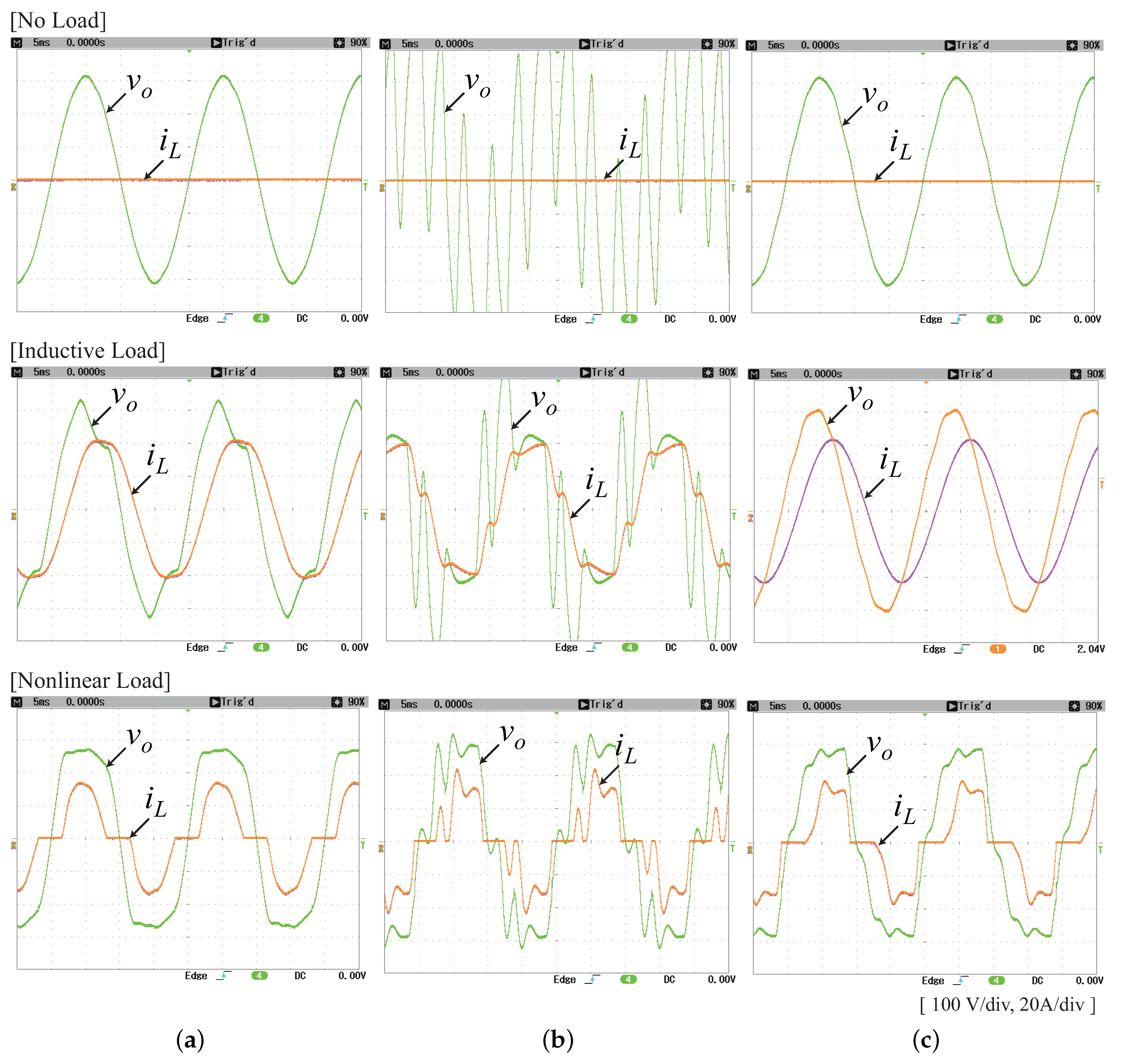
The controlled voltage outputs when a single 5-kW DG feeds the local AC bus at various load conditions are compared in
Figure 8. A severe distortion caused by resonance and PWM harmonics is evident with the conventional deadbeat voltage control even in the no-load condition in
Figure 8b. The LC resonance is not sufficiently damped by deadbeat voltage control alone. Note that the closed-loop poles of conventional deadbeat voltage control are placed very near to the unit circle in
Figure 7b. Note also that the disturbance observer is not adopted to exactly compare the control performance based on control design methods [
22]. In inductive and nonlinear load conditions, the controlled voltage output is still greatly distorted with conventional deadbeat voltage control. Although conventional deadbeat control is one of the fastest kinds of control, its disturbance response is not fast enough to compensate the load disturbance properly, as shown in
Figure 8b.
The value of the virtual damper was 3 ohms in
Figure 8c, which makes the damping ratio of the actively damped LC filter 0.23 in Equation (
4). Although it is less than 0.707, the resonance is sufficiently damped by the combined action of the deadbeat control law and the virtual damper in
Figure 8c. It is evident that stability and voltage control performance are greatly enhanced using the proposed deadbeat voltage control in
Figure 8c. It outputs better voltage waveforms in every load condition compared with the alternatives.
The controlled output voltage and load current waveforms when the conventional PI controller is adopted instead of the deadbeat controller are shown in
Figure 8a. The control structure is the same as shown in
Figure 5 except for the PI compensator. The value of the virtual damper is the same as that used in the proposed deadbeat control. Note that the virtual damper is essential to sufficiently increase the integral gain in direct voltage control with the PI controller [
24]. The proportional gain (
) and the integral gain (
) are 0.5 and 1480, respectively. As a result, the voltage control bandwidth is set to 6319 rad/s with a 12% overshoot. The total harmonic distortion (THD) was measured and is listed in
Table 3.
In the no-load condition, the measured THD is almost the same in the cases of PI control and the proposed deadbeat control. However, in the inductive load condition, much lower THD is obtained with the proposed deadbeat control. In the nonlinear load condition, it seems that PI control is slightly better than the proposed deadbeat control according to
Table 3. However, if we increase the value of the virtual damper from 3 to 5, the measured THD is considerably decreased from 10.06 to 2.67 with the proposed deadbeat control, as shown in
Figure 9c.
In practice, when PI voltage control is utilized with a virtual damper, the maximum value of
is limited and small because large
provokes a large phase delay in LC plant dynamics. Additionally, PI control gains should be tuned every time
is changed. However, with the proposed deadbeat control, the maximum value of
is only limited by the inverter’s DC link voltage and its control parameters need not be tuned again. This is another advantage of the proposed deadbeat control. Note that
is already included in the deadbeat design in Equation (
15).
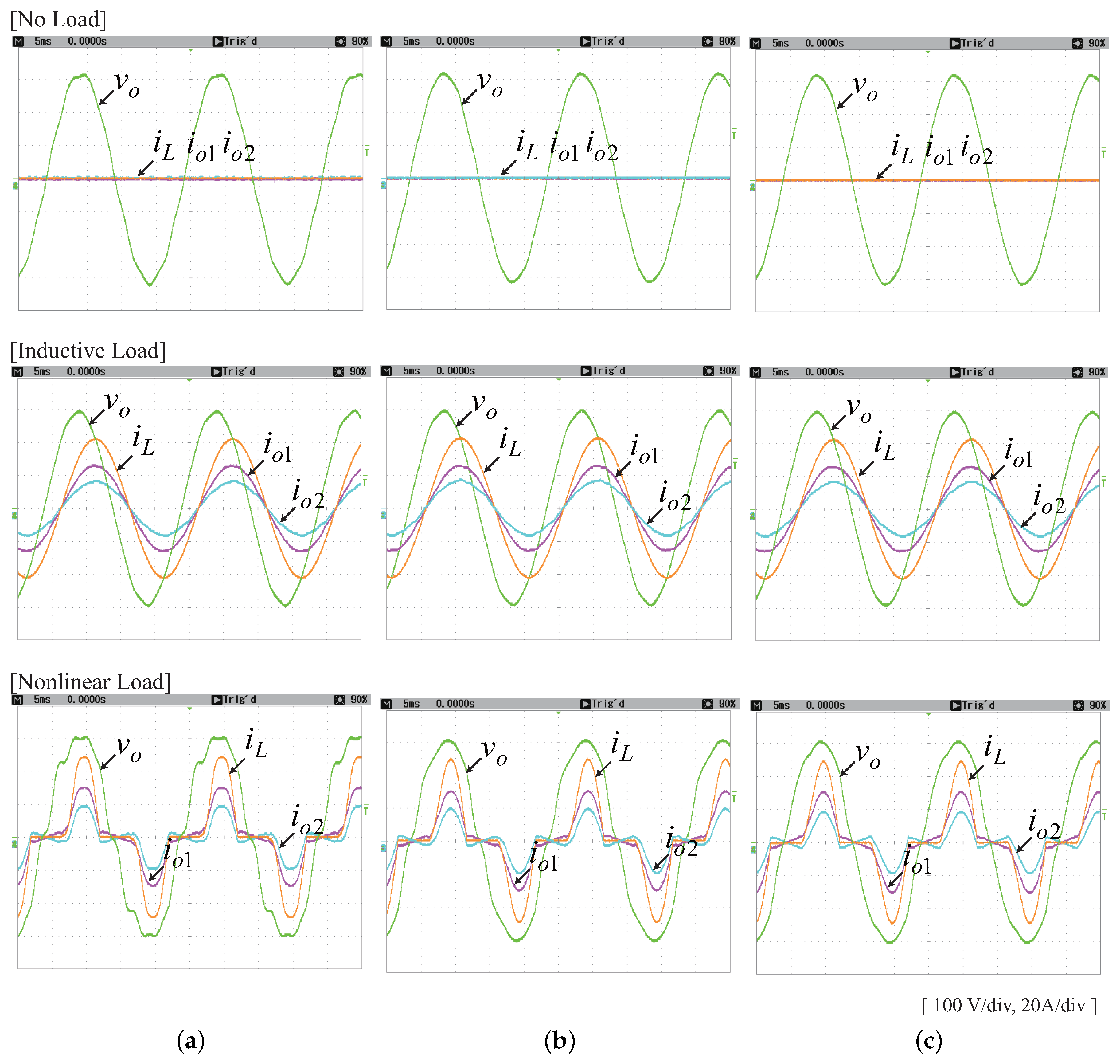
In a microgrid, more than one DG unit may operate at the same time. When two or more DG units operate in parallel in a microgrid, the droop method is often adopted to share the load based on the power rating of each DG unit [
32,
33]. The power-sharing performance of the droop method is strongly affected by the inner voltage control loop. Two DG units with 10-kW and 5-kW power ratings are connected in parallel to the local power bus and the proposed deadbeat voltage control is adopted for both DG units.
Figure 9 shows the controlled voltage and current waveforms in the steady state. The first DG unit with a 10-kW power rating is denoted by the subscript 1 and the second DG unit with a 5-kW power rating is denoted by the subscript 2. As the virtual damper,
, increases, less harmonic distortion in the local bus voltage is observed in every load condition. Moreover, as
increases, harmonic current-sharing performance is also enhanced in the nonlinear load condition. Thus, it can be concluded that better stability and faster disturbance rejection are obtained with large
.
For the grid-connected operation of the DG inverter, the control input
and feedback
in
Figure 5 are changed to
and
, respectively. The point of common coupling (PCC) should then be the LC filter output terminal [
3,
7].
,
, and
become zero. The discrete-time plant model becomes simply:
From the design procedure in
Section 3, the deadbeat current control law in Equation (
15) should be changed to:
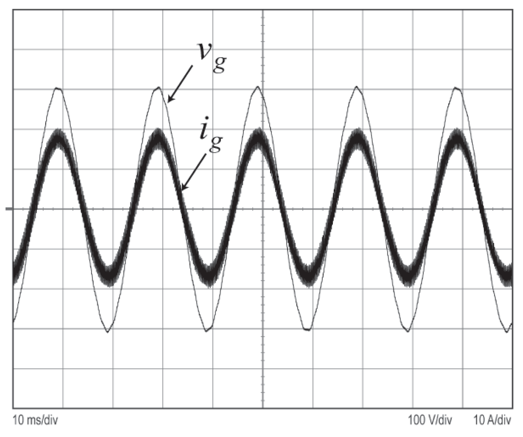
The resultant controlled current waveform is shown in
Figure 10. A few component changes in
Figure 5 for the grid-connected mode of operation make the controlled inverter current almost sinusoidal despite small grid voltage distortion. This change facilitates easy mode switching between the islanded and grid-connected modes of operation.


