1. Introduction
In the last years, environmental pollution and energy crisis have become problems of a global nature. The resulting increase in fuel costs and stringent regulations have prompted researchers and original equipment manufacturers (OEMs) to focus their attention on fuel consumption reduction and efficiency improvement, even in off-road mobile machinery. In particular, system hybridization has proved to be an effective technique to achieve these goals. Different solutions have been proposed for hydraulic excavators concerning potential and kinetic energy recovery from either the boom actuator or the turret.
The literature shows many examples of innovative system architectures taking advantage of hydraulic or electric energy storage devices such as hydraulic accumulators, electric batteries or supercapacitors. Some major excavator companies have already implemented these solutions on their hybrid excavators available on the market. Komatsu introduced the world’s first hydraulic hybrid excavator (HHE), which achieved about a 25% reduction in fuel consumption; the machine is equipped with an electric motor for the rotation of the upper structure which recovers and accumulates in a capacitor the energy collected during braking, permitting the engine to work in high efficiency areas [
1]; Caterpillar commercialized the first HHE which recovers the swing braking energy with a high pressure accumulator [
2]. Other companies like Hitachi [
3], Kobelco [
4] and Liebherr [
5] have exploited energy recuperation techniques with the common objective of enhanced energy efficiency and lower exhaust emissions.
Besides the hydraulic hybrid concepts proposed by companies, research groups and universities studied and implemented new hybrid solutions for mobile machinery. Lin et al. [
6] proposed an energy recovery system (ERS) for a hybrid excavator which combines the advantages of an electric battery and a hydraulic accumulator exploiting the regeneration power of the boom. Ho and Ahn [
7] presented a novel hydraulic energy regenerative system based on a closed-loop hydrostatic transmission using a hydraulic accumulator as storage device to recover the kinetic energy of the load. Wang et al. [
8] analyzed an innovative regeneration device which consists of an electric generator and a hydraulic motor, used to replace the traditional hydraulic compensator in order to obtain a more efficient hydraulic system. Joo and Stangl [
9] presented the application of a power regenerative boom (PRB) system to an excavator of large size; the circuit solution is quite similar to that proposed by the authors, but it requires the presence of a dedicated hydraulic motor to support the engine while in the solution proposed in this paper the pilot pump is used as motor and therefore a dedicated motor is not required. Vukovic et al. [
10] proposed a new system for mobile machines, based on constant pressure sources which improves the total system efficiency compared to the traditional load sensing (LS) system. Kim et al. [
11] developed a new regeneration scheme to recover the boom potential energy for hydraulic excavators by directly connecting the head chambers of the boom cylinders to a variable displacement hydraulic motor installed on the engine shaft.
Furthermore, different research activities deal with the development of control strategies in order to increase the system overall efficiency, reducing the energy losses and allowing the internal combustion engine (ICE) to work in areas with high efficiency. Li et al. [
12] proposed a control strategy for a hybrid excavator that combines a hydraulic accumulator and an electric regeneration unit. Zimmerman et al. [
13] dealt with the optimal control for a hybrid excavator with multi-actuator displacement controlled system using a state space model to apply dynamic programming (DP) algorithm; a rule-based control strategy was created to replicate the optimal control [
14] exploiting a methodology for the control definition similar to that proposed by the authors. Gong et al. [
15] introduced on a hybrid excavator a control strategy based on equivalent fuel consumption optimizing the power distribution and the ultra-capacitor working conditions. Casoli et al. [
16] presented a methodology to analyze, compare and optimally dimension ERSs for mobile off-road machinery, applied to an excavator, based on the DP algorithm [
17], typically exploited in order to define the optimal control policies. Shen et al [
18] proposed different strategies to reduce fuel consumption on a HHE based on common pressure rail (CPR) by using DP algorithm to obtain the optimal control variables.
Within this context, the authors, in collaboration with two Italian companies, developed an ERS which recovers the potential energy of the boom during the lowering phase and exploits this energy through the pilot pump, suitably modified so as to function as a motor. Unlike what is typically found in literature, the proposed solution does not require a redesign of the hydraulic circuit with expensive and extensive changes but aims to provide a hybrid system to be installed on a middle size excavator already on the market. Within this activity a HHE prototype, equipped with the proposed ERS, was realized and experimentally tested. The hybrid layout was already presented and described in detail in [
19] as well as the control strategy whose purpose is that of minimizing the fuel consumption. The following paper presents the results of numerical and experimental analysis conducted on the hybrid prototype. The model validation, conducted in terms of both hydraulic and mechanical variables and fuel consumption, showed the robustness and reliability of this mathematical tool whose potential can be exploited to conduct energy analysis, as will be described in the article, and to test other energy saving solutions. A dedicated experimental activity was performed on the HHE prototype in order to obtain data for both the model validation and fuel consumption evaluation. Single user movements and working cycles were performed on the field; the working cycles considered referred to the Japan Construction Mechanization Association Standard (JCMAS). Validation results in terms of hydraulic variables and fuel consumption are presented. Furthermore, the detailed energy analysis of the HHE is reported showing energy losses distribution within the system. Starting from this analysis, a numerical comparison between the standard and the hybrid excavator model was conducted highlighting the HHE advantages and drawbacks. Finally, fuel consumptions results are reported in other to validate the model and to show fuel saving percentages. An experimental fuel saving of about 4.5% has been observed over the trench digging cycle with the introduction of the proposed ERS. The model developed by the authors thus represents an important starting point for the development of other energy saving solutions and future steps will consider their implementation on the excavator model in order to further improve the machinery efficiency.
2. Hybrid Excavator Mathematical Model
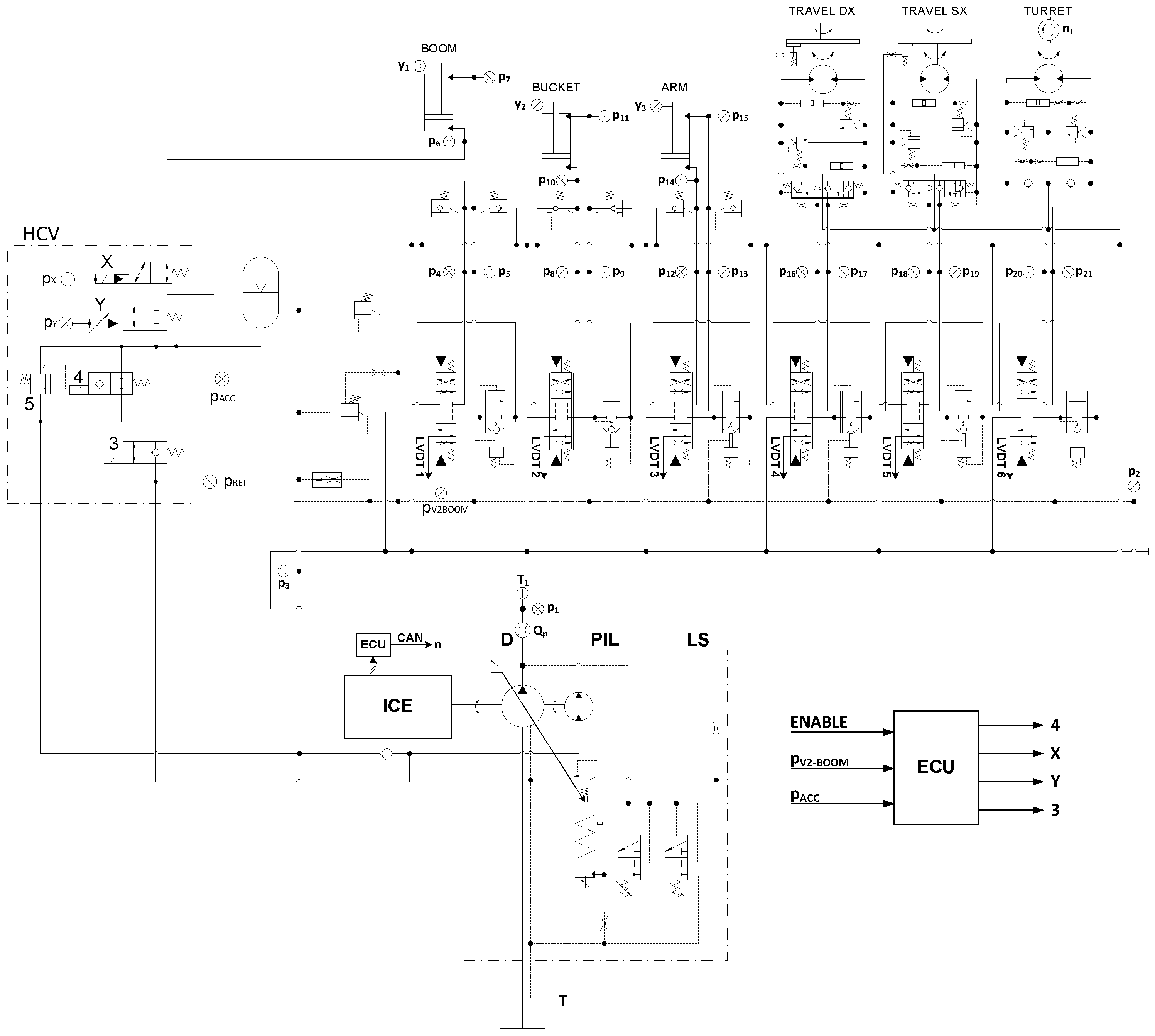
The machinery object of this study is a middle size (9 t) excavator equipped with a 46 kW diesel engine whose hydraulic system is a LS type. The hydraulic system of the excavator is composed of a flow generation unit (FGU) comprising a variable displacement axial piston pump and an external gear pump for the pilot hydraulic circuit, a LS flow sharing valve block with nine users (only six of which—boom, arm, bucket, turret and the two travels—were included in the mathematical model).
The HHE layout was defined on the basis of the hybridization methodology which exploits the DP algorithm presented in [
16]. The DP methodology permits comparing different hybrid layouts, at their maximum potential, i.e., with the optimal components sizing and the optimal control strategy. Starting from the inverse causality mathematical model of the standard excavator, the optimal strategy was developed knowing a “priori” the reference cycle that the hydraulic actuators have to accomplish. In order to develop a casual strategy implementable on an electronic control unit (ECU), able to manage the different operating conditions of the machine, a sub-optimal rule-based control strategy was introduced [
19].
The standard configuration of the machinery was modified with the introduction of the developed ERS, composed of four components: a hybrid control valve (HCV), a hydraulic accumulator, a hydraulic pilot pump/motor and an ECU [
19].
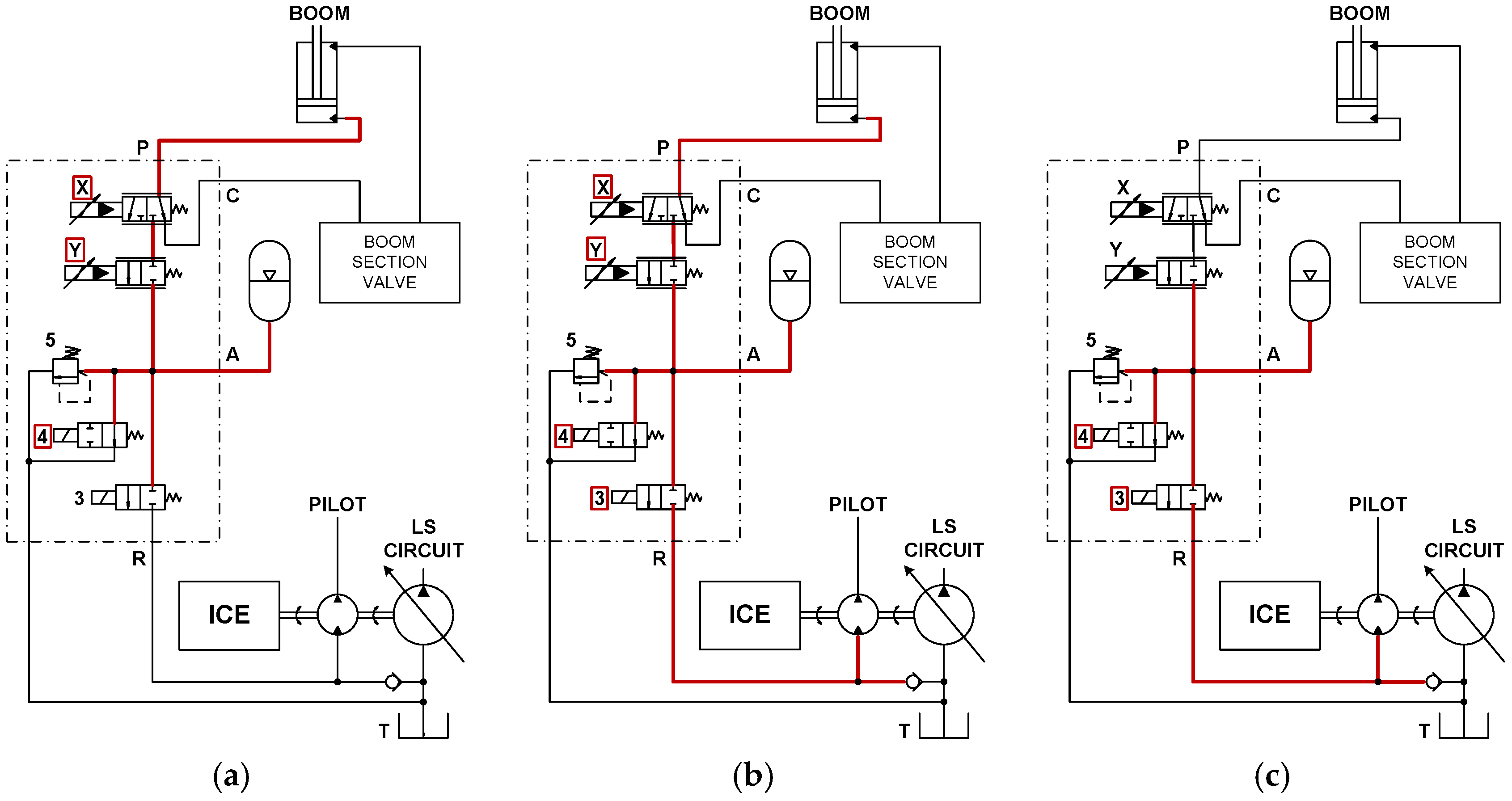
Figure 1 shows the hydraulic schematic of the proposed ERS and highlights the fluid path and the activated valves for the different operating modes: recovery mode (
Figure 1a), recovery and reuse mode (
Figure 1b) and reuse mode (
Figure 1c).
The energy recovery occurs during the boom lowering. The energy flow coming out from the piston side of the boom actuator is directed towards the hydraulic accumulator by the actuation of the on/off valve X; when the valve X is disabled the flow is directed towards the flow control valve and the ERS is bypassed (standard mode). Since in some operating conditions the accumulator pressure could be not enough to balance the front equipment weight, valve Y, proportionally controlled, allows to manage the boom descent, improving the load controllability and avoiding cavitation in the rod side of the boom actuator. The hydraulic energy stored in the accumulator is reused through a hydraulic motor by activating the on/off valve 3. The hydraulic motor is installed on the ICE axis and acts also as pilot pump. By operating valve X and valve 3 simultaneously the energy coming from the boom actuator can be directly regenerated through the hydraulic pump/motor (operating mode in
Figure 1b). Concluding the description of the HCV, valve 4, on/off controlled, connects the accumulator to the reservoir when the hybrid mode is disabled or the machine is shut off and the relief valve 5 prevents the accumulator from overpressures.
The mathematical model of the HHE was developed exploiting the models of both the standard excavator layout, presented and validated in [
20] and the ERS one in [
19]. The assumptions made for the hydraulic circuit, working fluid, kinematic bodies and boundary conditions are:
Constant air temperature and density;
Constant pressure in the reservoir;
Constant temperature of the working fluid;
Negligible inertial effects of the fluid in the pipes and hoses;
Mechanical bodies are considered as rigid;
Mechanical joints have one degree of freedom;
Absence of friction in the revolute pairs.
The excavator mathematical model is based on a grey box model of the variable displacement axial piston pump, a white box model of the flow sharing load sensing directional valve, a kinematics and dynamics model of the front tool, turret and tracks, and the ICE model. The models of the different components were realized following a lumped parameters approach which is often utilized for the simulation of hydraulic systems [
21,
22,
23,
24] since it allows one to combine good reliability with an acceptable simulation time. The numerical model of the variable displacement pump considers the swash plate as a rotary inertia and includes detailed models of the torque limiter, the flow (load sensing) compensator and the pressure compensator in order to model precisely the control action on the swash plate. The models of the three compensators follow a lumped parameters approach and combine a mechanical model, based on the Newton’s second law, for the evaluation of the spool position and a filling and emptying model which calculates pressures and flow rates through the pressure-rise rate (Equation (1)) and the orifice (Equation (2)):
where
is the pressure in the defined control volume;
is the volume of the control volume;
is the total mass flow rate entering the control volume;
is the bulk modulus of the fluid; and
is the fluid density.
where
is the mass flow rate through the orifice;
is the differential pressure across the orifice;
is the flow area; and
is the flow coefficient. The position of the swash plate derives from the equilibrium of the control action and a counteracting torque which was measured in a broad set of operating conditions through dedicated experiments and introduced in the model by means of a map. The hydromechanical and volumetric efficiencies were introduced in the model by means of maps as well. More details about the pump mathematical model and its experimental validation can be found in [
25]. The numerical model of the LS flow-sharing distributor includes a section for each of the considered users and was developed following the same lumped parameters approach used for the pump’s compensators and briefly described above. Dedicated experiments were performed on the distributor on a test bench in order to validate its numerical model [
26]. The model of the excavator was developed in the AMESim
® environment and the planar mechanical library was exploited for generating a 2D kinematics and dynamics model of the front equipment in order to create realistic loads on the actuators. The model, based on the Lagrange equations, is composed of five rigid bodies whose parameters of interest such as body mass, position of the center of gravity, moment of inertia and joints position were obtained with the support of the 3D geometrical model of the front equipment. The load on the rotary actuators, i.e., the hydraulic motors of the turret and of the two tracks, was modelled considering a rotary inertia with Coulomb friction torque and viscous friction coefficient; the friction coefficients were defined so as to match with experimental results [
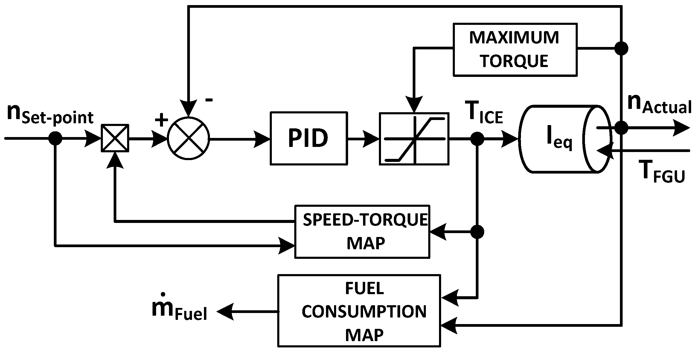
20]. The ICE model, whose modelling scheme is reported in
Figure 2, permits one to calculate the instantaneous engine fuel consumption and the actual engine speed, having as inputs a set-point value for the angular velocity and the torque required by the FGU.
The ICE model is based on a proportional integral derivative (PID) regulator which defines the engine torque in order to reduce the error between the set-point speed (
Set-point) and the actual speed (
Actual). The latter is obtained from a dynamic equilibrium of a rotary mass whose moment of inertia (
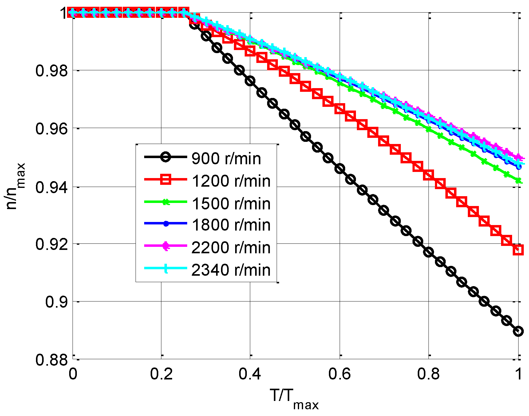
eq) includes both the ICE and the flow generation unit ones. The PID parameters were set in order to follow the speed variations detected during transient conditions and the engine torque is limited to the highest value set by the manufacturer. Since the angular velocity setting decreases when the torque increases, an experimental map was utilized to estimate a reduction coefficient for the set point speed as a function of the engine torque (
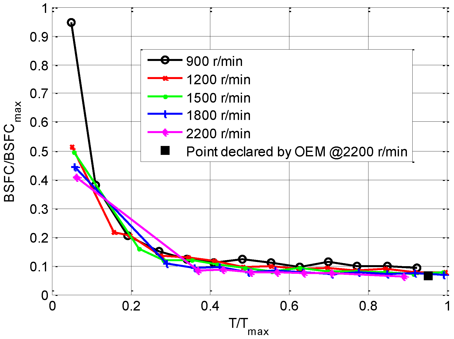
Figure 3). The engine fuel consumption (
) is calculated through a steady state fuel consumption map, experimentally defined as a function of torque and angular velocity (
Figure 4).
The operator model is also based on a control logic in feedback, exploiting a proportional integral (PI) controller. The error between the actual position and the desired one enters the controller which defines as output the spool position of the flow control valve. This model permits to control the users so as to reproduce in simulation the desired working cycles.
Once validated the single hydraulic components, the complete model of the standard machinery was calibrated and validated with a dedicated experimental activity [
20]. Starting from the excavator standard model, the hybrid one has been developed with the introduction of the ERS model; this last was presented and validated in [
19]. The model of the ERS was developed following the same modelling approach which had already been used for the pump’s compensators and the distributor. In particular, the pressure time derivative in the hydraulic accumulator is evaluated considering an adiabatic gas transformation in Equation (3):
where
is the accumulator pressure (both of the oil and the gas);
is the gas volume in the accumulator;
is the oil mass flow rate entering the accumulator;
is the oil density; and
is the adiabatic index. The model of the ERS was then validated with experimental results obtained through dedicated test bench experiments [
19].
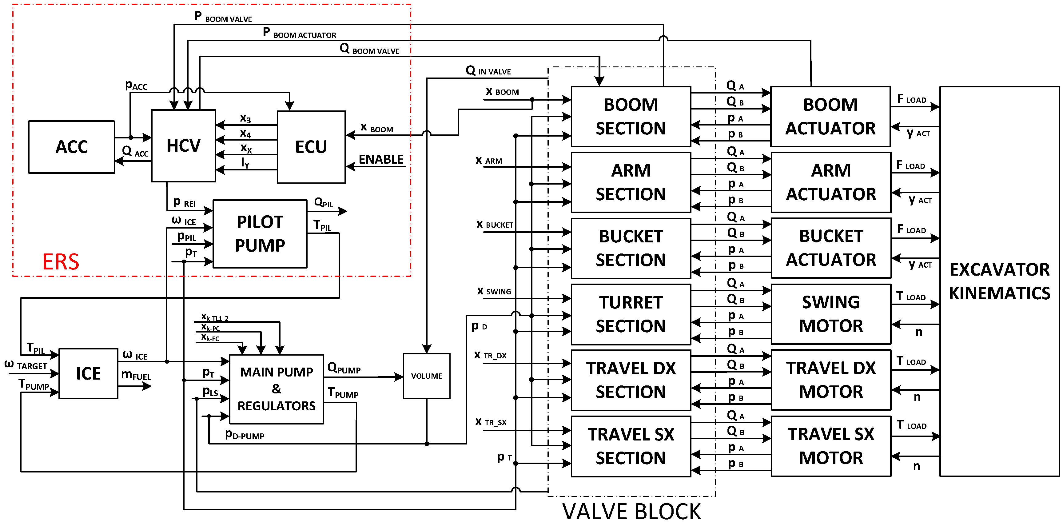
Figure 5 shows the mathematical model causality scheme of the HHE exploiting the proposed ERS. All the components interact each other with the physical causality (direct causality). The overall inputs are the positions of the spools of the distributors defined by the operator model and on the basis of these inputs the actuators follow the desired working cycle.
3. Experiments
The experimental activity carried out on HHE has the double purpose of verifying the correct functioning of the realized prototype and obtaining useful data for both its mathematical model validation and fuel saving definition in comparison to its standard configuration.
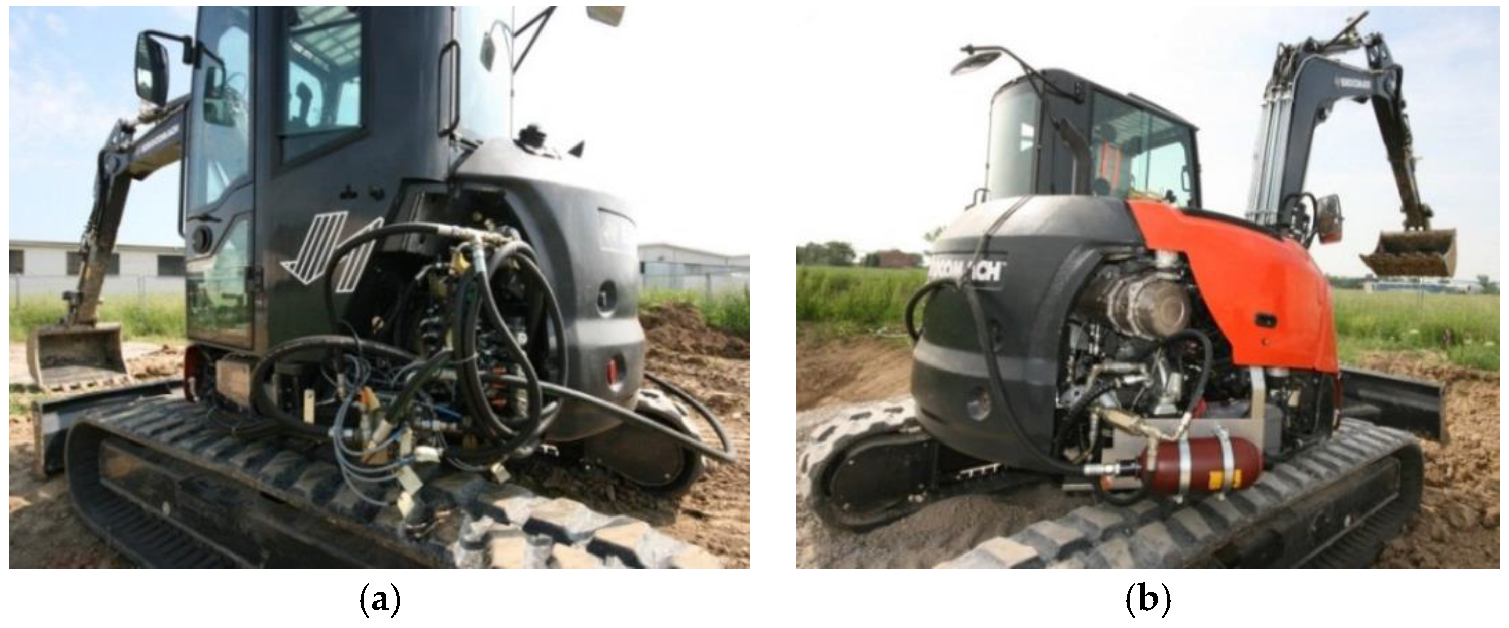
Figure 6a,b shows different views of the instrumented HHE prototype on the field during tests. In
Figure 6a the HCV valve block, opportunely instrumented can be seen, while
Figure 6b shows the hydraulic accumulator connected to the machinery frame with dedicated steel clamps, on the opposite side of the excavator.
The standard excavator hydraulic system was already instrumented in previous activities with the aim of calibrating and validating the standard mathematical model, as described in [
20]. Consequently, the HHE prototype required the instrumentation of the hydraulic system concerning the ERS.
Figure 7 reports the hydraulic scheme of the experimental setup of the hybrid excavator prototype.
Table 1 reports the transducers placed on the hybrid prototype and their main features.
The excavator was instrumented in order to acquire the variables of interest during the different performed working cycles. Two different types of cycle were carried out:
Boom down-up cycle;
JCMAS working cycles.
The single user movement (boom down-up) was executed in order to characterize and validate the HHE model with the ERS. Moreover, this cycle allowed to study in detail the impact of the ERS on the system behavior, i.e., implement velocity, oscillations and cavitation.
Concerning the fuel consumption estimation, the operating modes, defined by the standard (JCMAS [
27]) were performed. The standard defines four different operating modes (trench digging, grading, travelling and standby) as well as the number of minimum repetitions required. The aim is that of evaluating a mean fuel consumption for each operating mode, highlighting the fuel saving compared to the standard machinery.
Furthermore, the experimental fuel consumption results will be very useful in order to validate the model capability in fuel consumption prediction. The standard defines also an equivalent working hour consumption (
) which represents the machinery fuel consumption during a typical working hour, defined according to Equation (4):
The coefficients
C1,
C2,
C3,
C4 were determined by the standard referring to the typical frequency of use of the different cycles during the machinery lifetime.
Table 2 reports the value of the parameters defining the operating conditions on a typical excavator working hour.
In order to reduce stochastic influences on the average fuel consumption of each operating mode, the number of repetitions has been significantly increased in comparison to what is reported in the standard. Furthermore, the combined standard uncertainty with a 95% confidence level was defined for each operating mode and it was used as a parameter for the model validation. The combined standard uncertainty (
UC95) considers both the transducers uncertainty and the stochastic influence of operator drive, according to Equation (5); the expansion factor (
k) is set equal to 2 [
28]:
4. Model Validation
In this section the mathematical model validation of the HHE is presented, comparing the experimental data obtained during tests carried out on field and the simulation results. The model validation is based on the numerical-experimental comparison between hydraulic and mechanical variables during the boom down-up cycle and between the fuel consumptions during the different operating modes defined by the JCMAS.
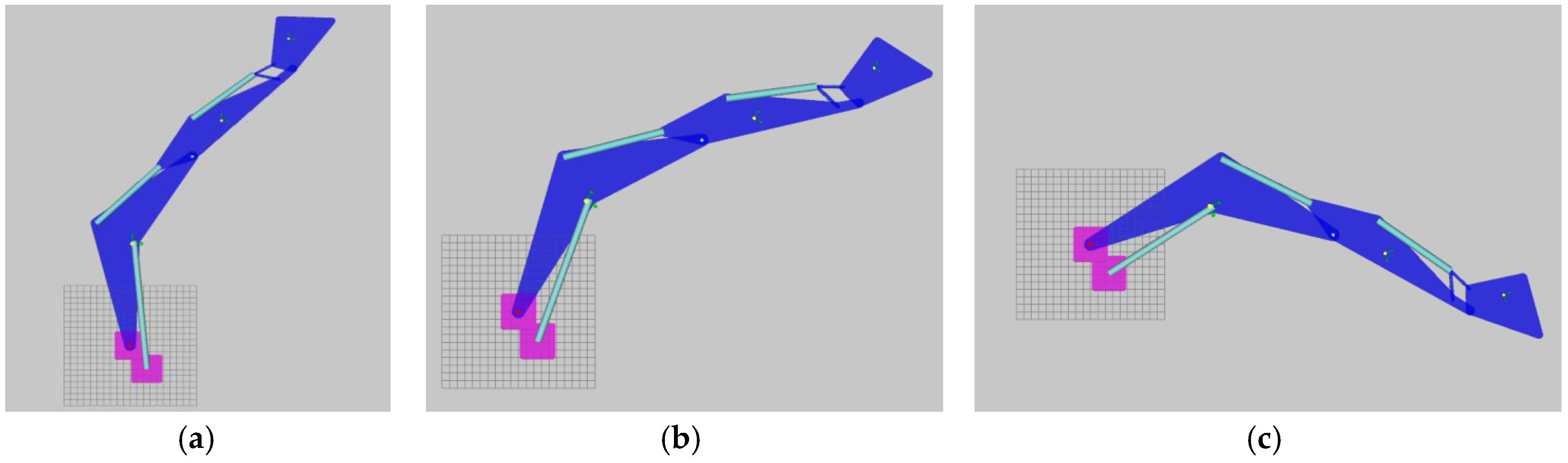
The first part of the model validation is focused on the hydraulic circuit of the HHE involving the ERS. The considered boom down-up cycle is a single user movement during which the boom, starting from a position of maximum extension, lowers until the front excavation tool reaches the initial position defined by the JCMAS and then it returns to the starting position. The same operating conditions of the experimental tests were set up during the simulations, i.e., the same initial position of the front excavation tool, ICE speed and boom main spool displacement were imposed.
Figure 8 reports the boom down-up cycle simulated. The sequence of images shows the positions of maximum, intermediate and minimum extension of the boom actuator, illustrating the executed cycle.
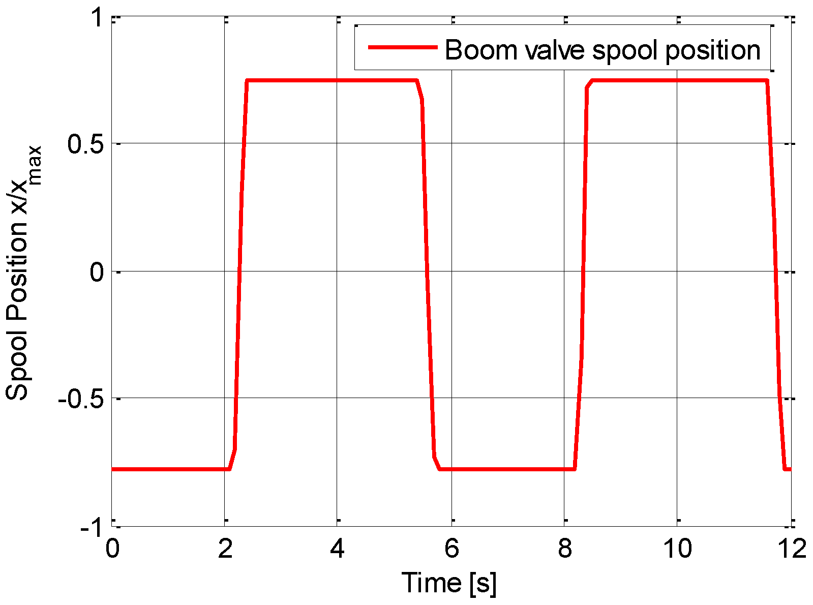
The following figures show the comparison between the experimental and numerical results of two consecutive repetitions of the boom down-up cycle. The spool position of the boom valve section, measured experimentally and showed in
Figure 9, was imposed as an input, replacing the operator model; this permitted to evaluate the behavior of the hybrid model receiving as input experimental data.
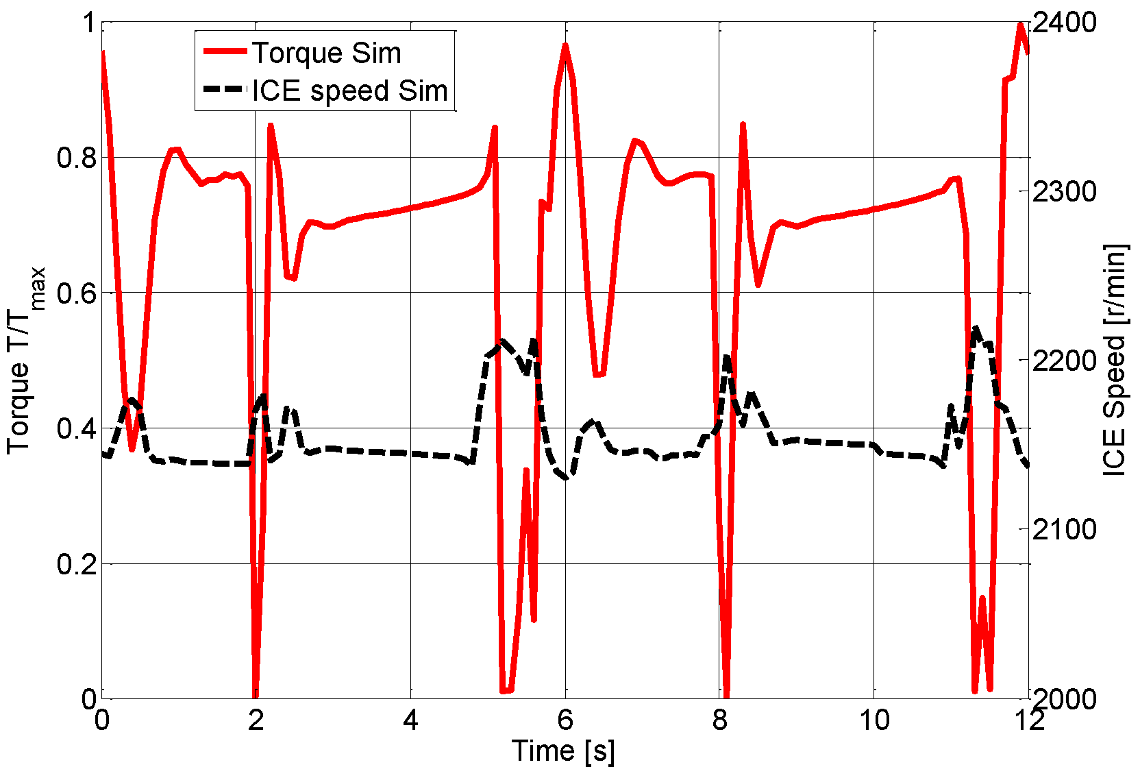
Figure 10 reports the numerical ICE torque and speed calculated by the mathematical model, pointing out the good behavior of the ICE model, previously presented. In more detail, the target rotational speed is clearly lower for higher torque values; e.g. at the time of 4 s the torque is about 72% of the maximum value and the target speed is about 2150 r/min instead of the rated speed set equal to 2200 r/min.
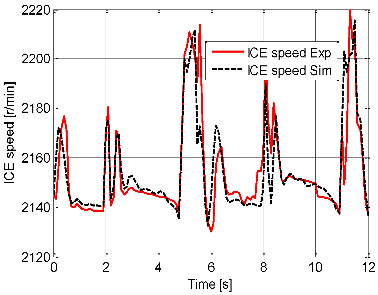
Figure 11 reports the numerical and experimental ICE speed; a satisfying prediction was obtained.
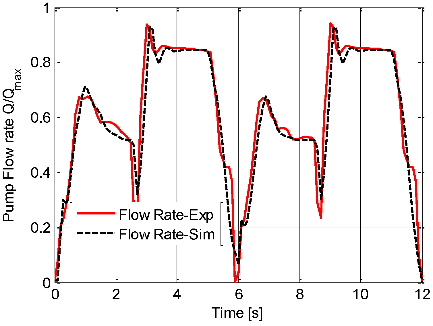
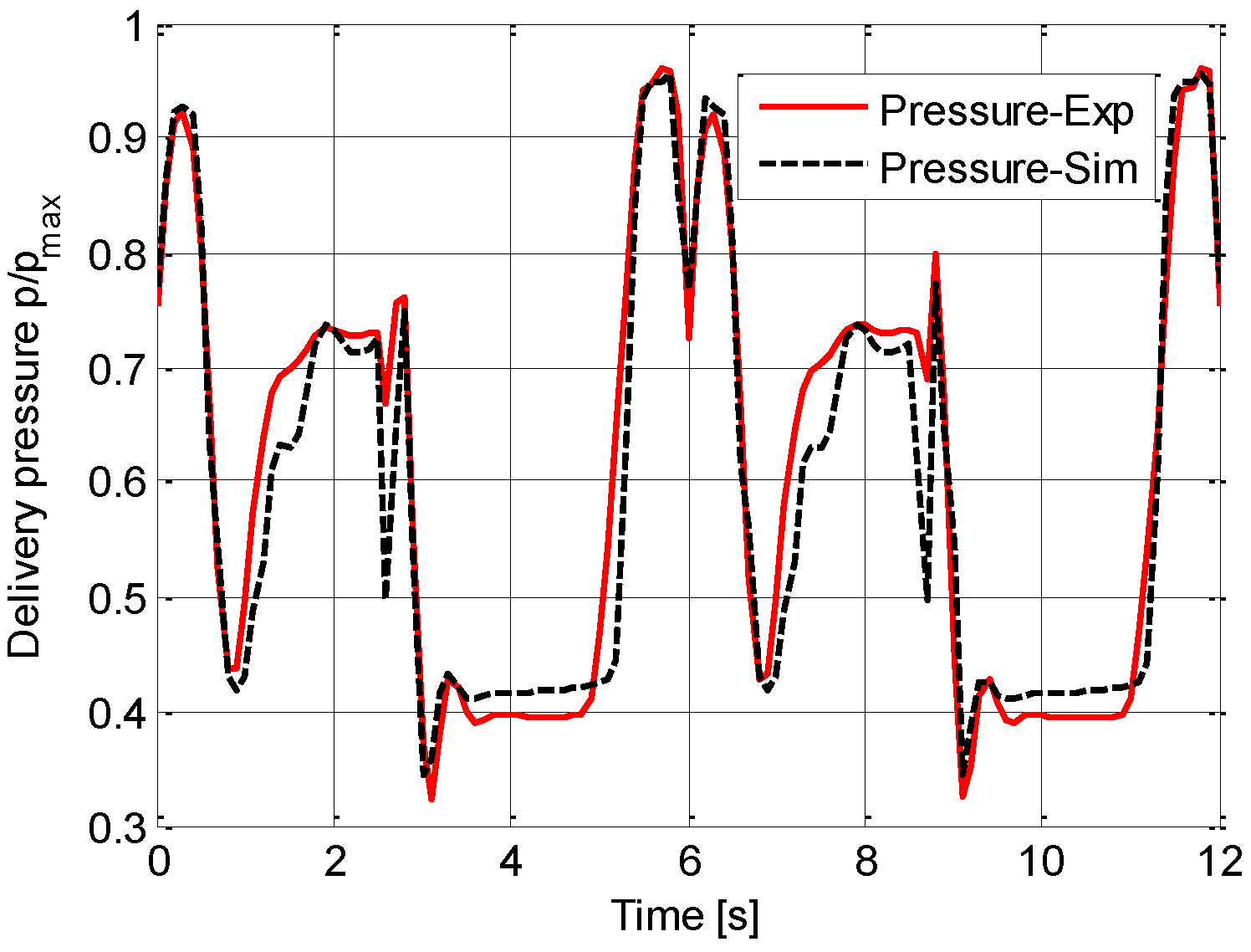
Figure 12 and
Figure 13 report the comparison of the delivery flow rate and the system pressure; the pump grey box model implemented is able to predict the flow rate which comes from the instantaneous combination of pump displacement and pump shaft speed.
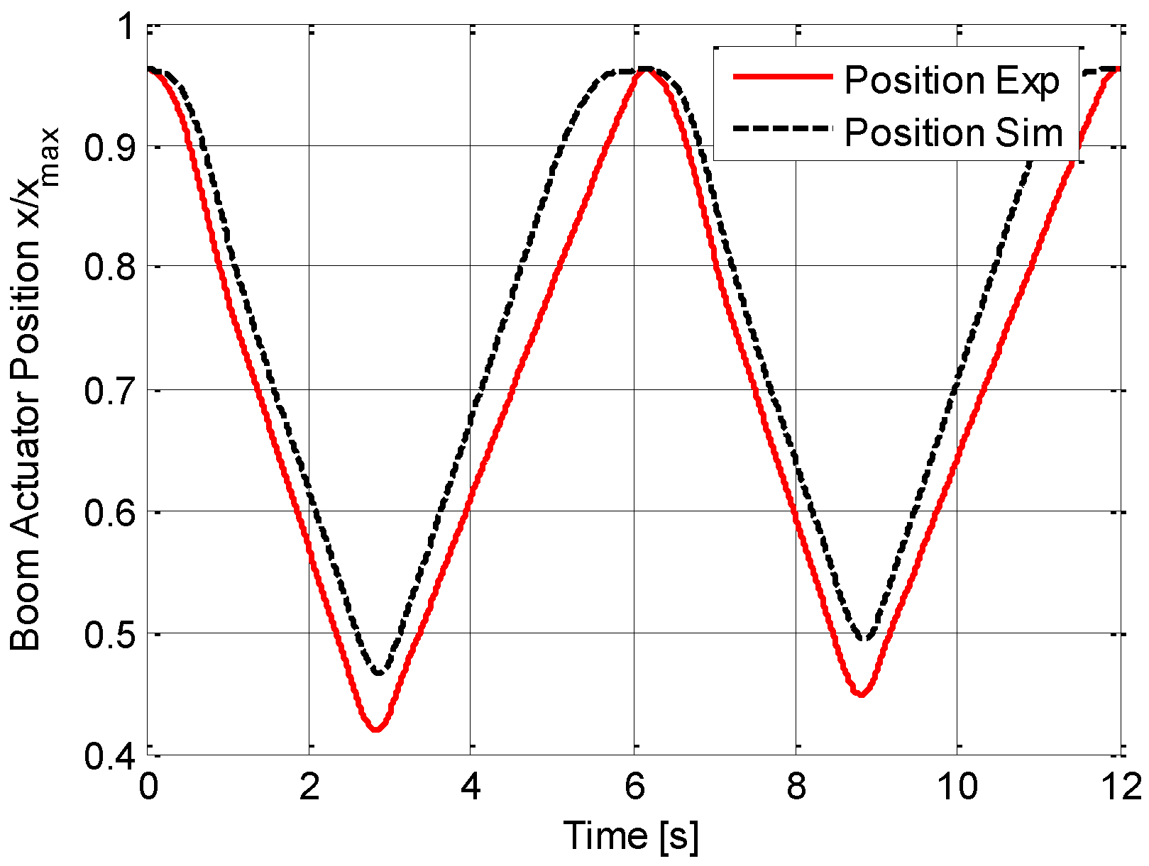
Figure 14 shows the comparison between the numerical and the experimental position of the boom actuator, pointing out the reliability of the operator model, which permits to guarantee the same kinematic movements on the simulated cycles.
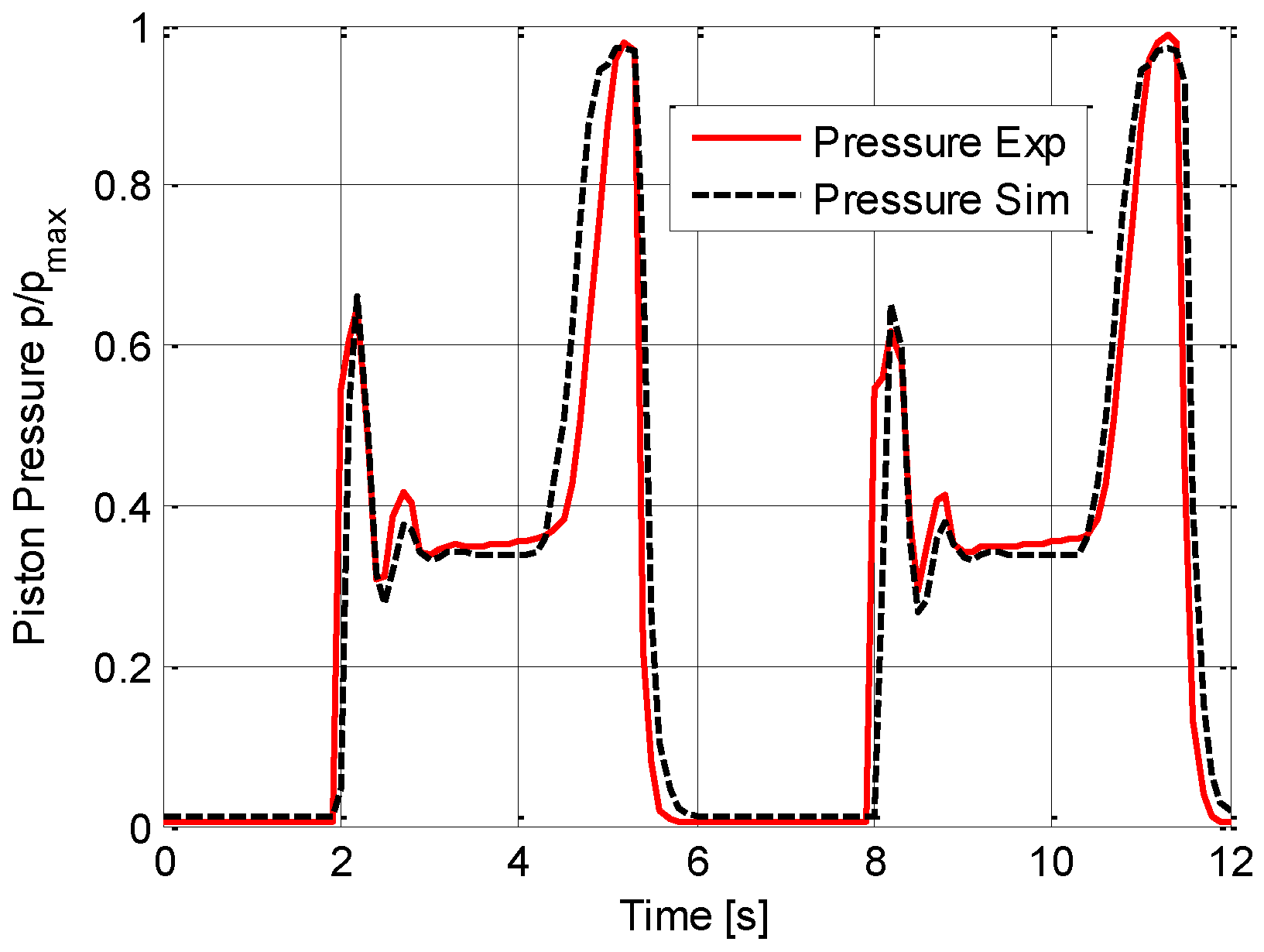
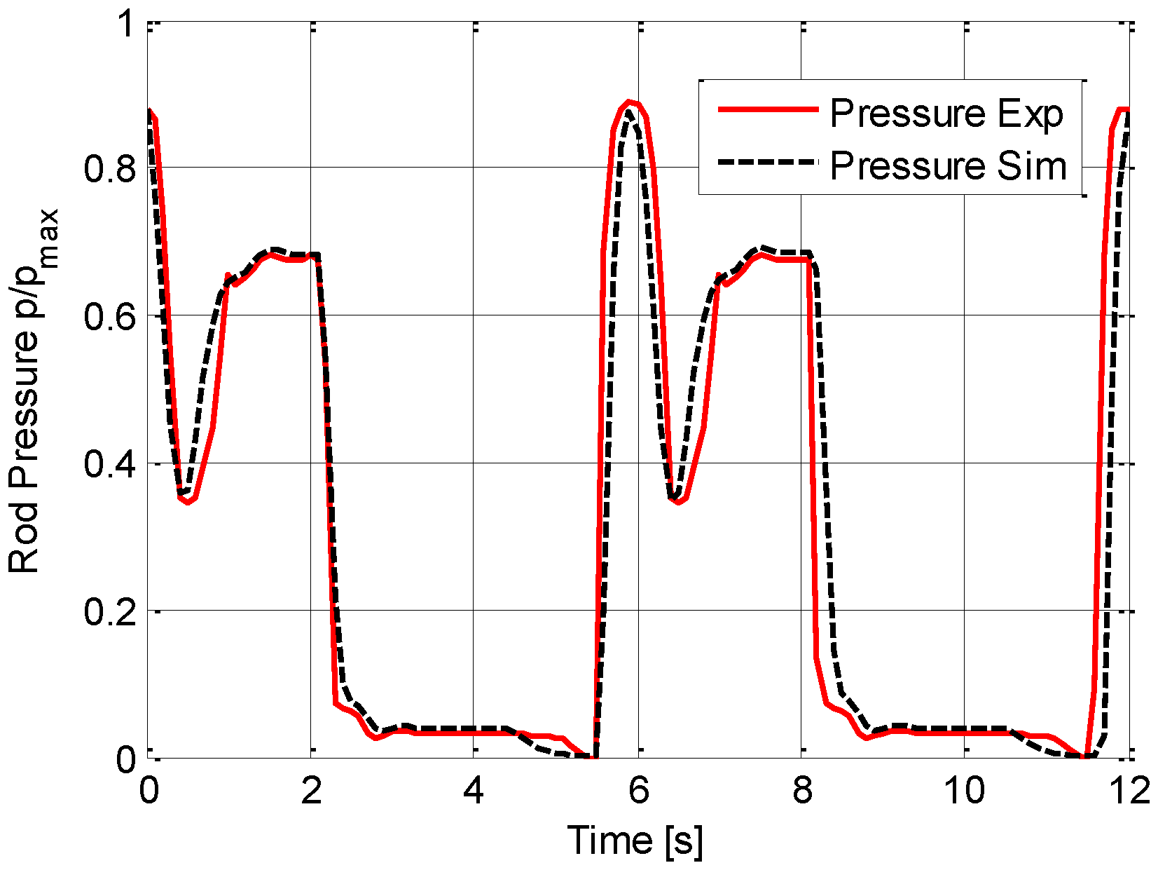
Figure 15 and
Figure 16 show the rod side and piston side pressures of the boom actuator.
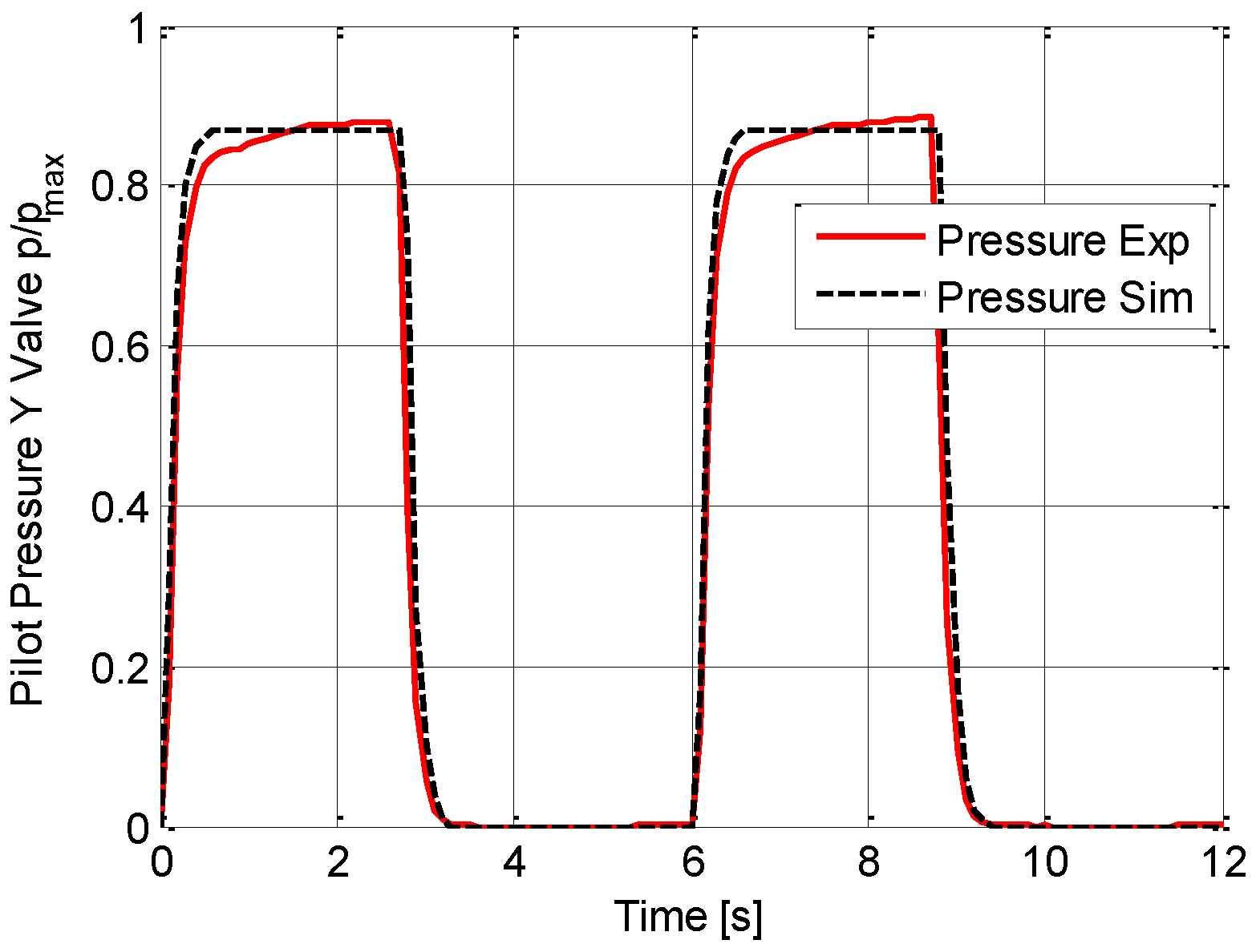
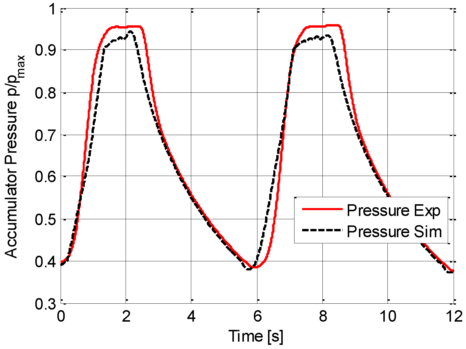
Finally,
Figure 17 and
Figure 18 report the variables of interest of the ERS system; the first shows the pilot pressure of valve Y, proportionally controlled, whose main task is that to manage the boom descent, improving the load controllability, while the second shows the accumulator pressure. In more detail, in the time interval 6–9 s, during the boom descent, pilot pressure of the valve Y increases opening the valve while the accumulator pressure rises. In this way, the valve Y is fully open when the accumulator pressure is the highest; furthermore, the boom descent is balanced by the accumulator pressure.
The comparison between the reported curves in the previous figures shows a good match between numerical and experimental results, highlighting the good functioning of the ERS and the reliability of the HHE mathematical model. It can therefore be concluded that the assumptions (listed in
Section 2) considered for the numerical model, which are typical in the lumped parameters modelling of hydraulic circuits, are acceptable for the development of an excavator dynamic model.
Concerning the model capability in fuel consumption prediction,
Table 3 reports the numerical and experimental machinery fuel consumptions over the different operating modes and during a typical working hour (JCMAS cycle).
The percentage differences between simulated and experimental fuel consumption results, calculated according to Equation (6), are always within the combined uncertainty limits experimentally defined for each operating cycle:
Therefore, the mathematical model has shown its capability in fuel consumption prediction. On the basis of the reported comparisons, the HHE model is validated both in terms of hydraulic variables and in terms of fuel consumption.
Being now confident on the HHE mathematical model results, the energy analysis of the system can be performed. Evaluations will be made in order to point out the differences referring to the standard layout and to find those parts of the circuit that are sources of energy losses. Furthermore, the energy analysis will permit to identify the drawbacks of the proposed HHE layout, paving the way for further improvements.
5. Energy Analysis
A detailed energy analysis by means of the excavator mathematical model for both the standard and the hybrid configurations of the machinery under investigation was conducted; the aim is that of quantifying the energy losses in the systems, showing advantages, weaknesses and possibilities to further improve the energy efficiency.
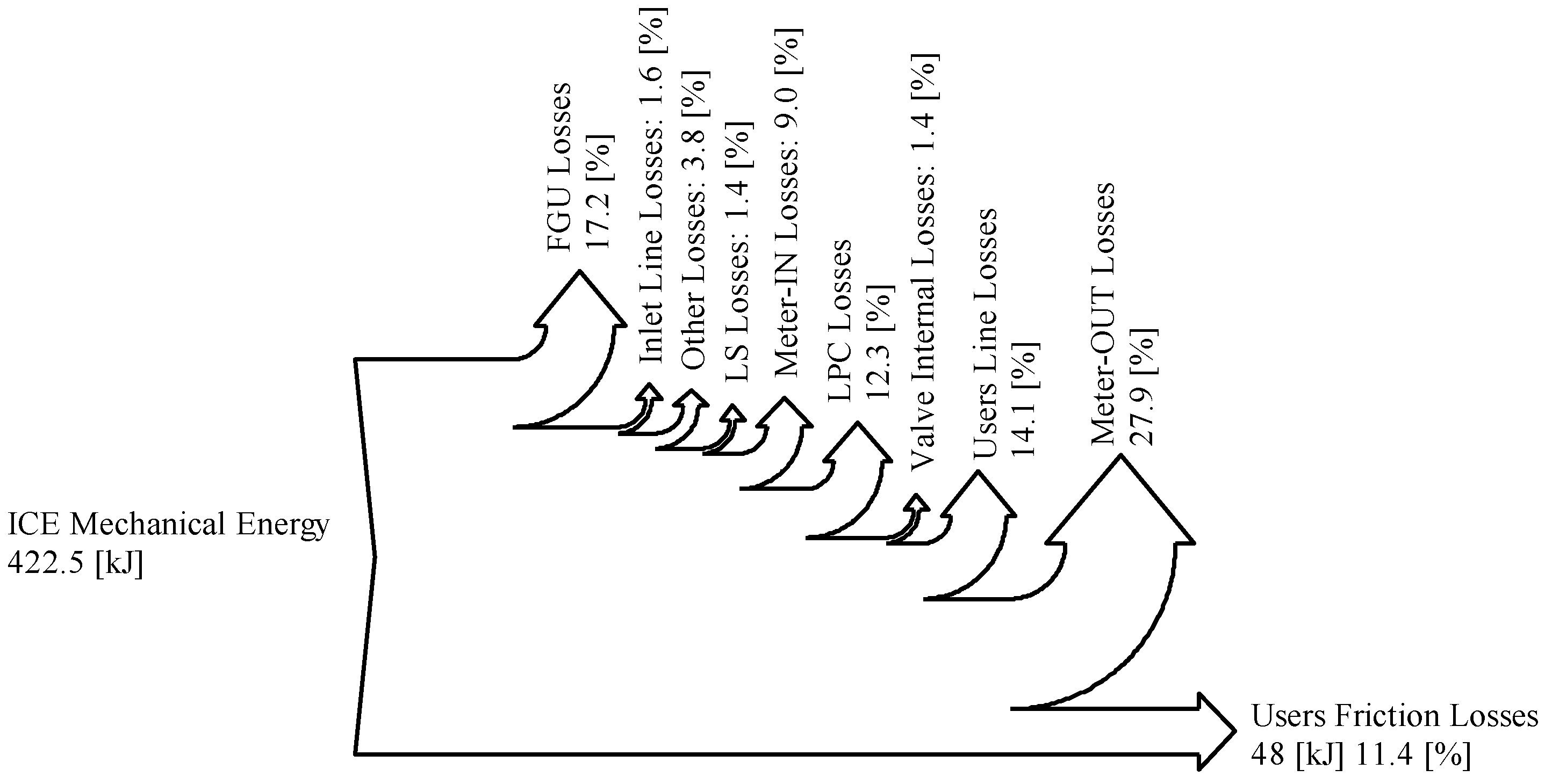
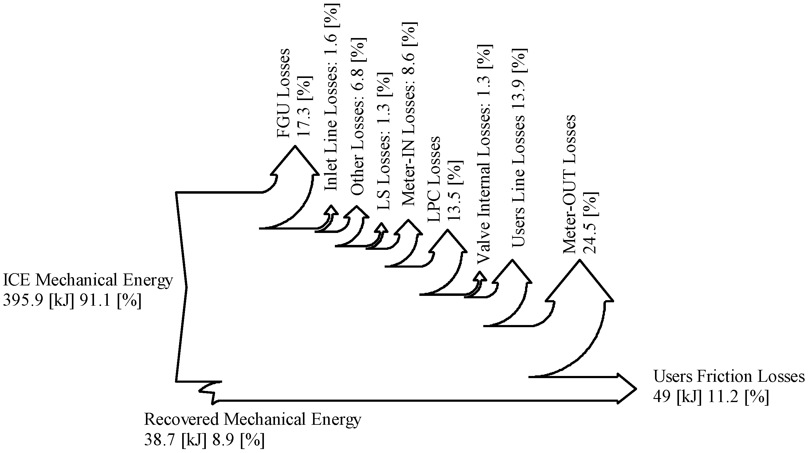
Figure 19 and
Figure 20 show the energy distribution among the different parts of the excavators starting from the ICE mechanical energy, during the trench digging cycle. The major losses pointed out are related to the meter-IN and meter-OUT sections of the distributor, the local pressure compensator (LPC), the connection lines between the distributors and the actuators and the FGU. The useful work for the trench digging cycle, defined by the JCMAS, corresponds to the required energy related to frictions forces and torques during the front excavation tool movements, being the interaction with the ground not considered.
The comparison between the energy flow diagrams of the standard and the hybrid excavator points out the advantages coming from the introduction of the proposed ERS, which allows the energy recovery from the boom actuator during its lowering phase. This energy is stored in a hydraulic accumulator and reused through the pilot pump which works as motor, reducing the torque required to the ICE. As can be seen in the Sankey diagram, about 9% of the mechanical energy of the hybrid machinery is provided by the pilot pump/motor. In
Figure 20 the hydraulic energy which is recovered in the ERS is computed in the meter-out losses; indeed, in the standard excavator this energy would be wasted in the discharge orifice of the boom flow control valve. This recovered hydraulic energy is then used in the pilot pump/motor to generate the recovered mechanical energy entering the system. However, there is an increase of the mechanical energy required by the hybrid system of about 3% due to a pressure rise in the piston side of the boom actuator during the recovery phase in which the accumulator is charging. Meter-OUT energy dissipations are reduced because of the lower outlet pressure imposed by the HCV in the first part of the actuator movement. These advantages in terms of energy saving are however partially countered by the increasing of the LPC energy losses due to the functioning of the hydraulic circuit in LS logic.
Figure 21,
Figure 22,
Figure 23 and
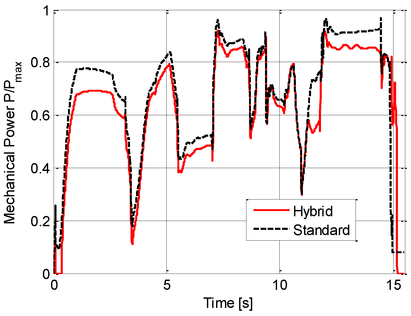
Figure 24 show the numerical comparison between the standard and the hybrid excavator variables of interest. In
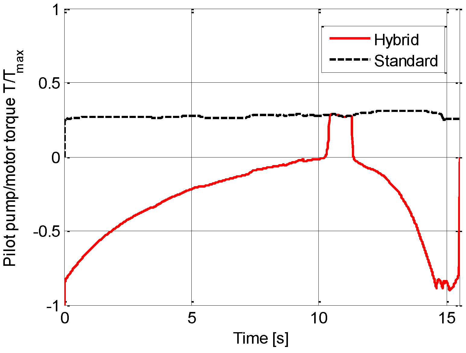
Figure 21, the advantage in terms of mechanical power (provided by the ICE) that the hybrid system ensures during the entire trench digging cycle can be seen; this is due to the fact that part of the torque supplied to the FGU is generated by the pilot pump/motor. Focusing on the pilot pump/motor,
Figure 22 shows the torque required by the pilot pump/motor, when the torque is positive the machine works as pump while when the torque is negative, the machine works as a motor. With the proposed hybrid solution, during the entire trench digging cycle the pump works as motor and exploits the energy coming from the ERS, with the exception of a short time interval in which the reuse phase is not enabled and the torque is only supplied by the ICE (time interval 10.4–11.3 s).
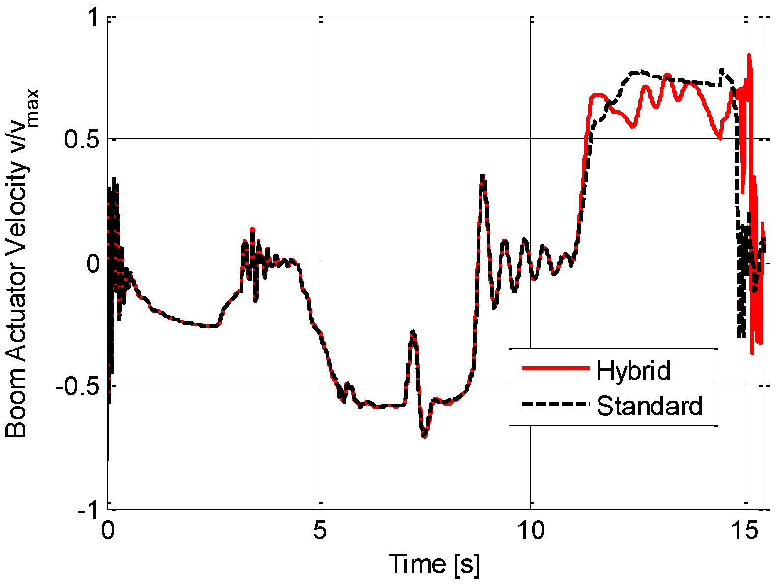
As experimentally observed, the boom actuator velocity, shown in
Figure 23, is slightly reduced during the last part of the lowering phase (time 11.8–14.8 s) because of the increase of the accumulator pressure during the charge phase. The velocity differences find explanation in the increase of the system pressure due to the accumulator presence. This causes a stronger operation of the pump torque limiter.
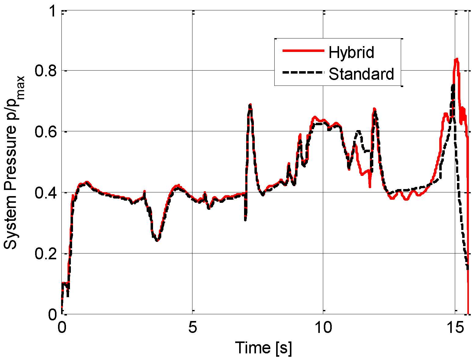
Figure 24 reports the main pump delivery pressure, showing again the different behaviour of both configurations in the final part of the trench digging cycle due to the increase of the accumulator pressure.


