1. Introduction
Significant research efforts have recently been dedicated to direct alcohol fuel cells, especially in consideration of the fact that this technology is characterised by specific advantages with respect to competing technologies in terms of fuel handling, distribution, high energy density, and reduced environmental impact. Alcohol fuels are characterized by high energy density, easy handling and storage properties, and good electromotive force when used in electrochemical systems [
1,
2,
3]. Methanol electro-oxidation occurs even at low temperatures, guaranteeing rapid start-up for these fuel cell devices.
In principle, direct methanol fuel cells (DMFCs) are characterized by lower constraints than a hydrogen-fed polymer electrolyte fuel cell (PEMFC) system. The latter generally suffers in terms of fuel storage and handling [
4]. However, despite the large efforts addressed to the development of methanol electro-oxidation catalysts, the reaction kinetics are significantly better in the case of the hydrogen oxidation process. This factor, together with the occurrence of methanol crossover through conventional fuel cell membranes, has limited the wide-scale deployment of the DMFC technology [
5]. A DMFC is based on a simple zero-gap electrochemical cell, with a polymer electrolyte membrane as a separator between the electrodes, flow field plates for diffusion of reactants, and collection of electrical current and reaction products. This system is able to oxidize methanol at the anode compartment directly, by means of a bimetallic Pt-Ru catalyst.
The commercialisation of DMFC systems is at an early stage despite the fact that this technology is being studied worldwide. DMFC fuel cells are environmentally friendly and low-polluting energy conversion devices (only carbon dioxide and water are produced under operating conditions). The total reaction taking place in the cell is:
Potential applications mainly include auxiliary power units (APUs) for telecommunications and campers, consumer electronics (1–50 W), e.g., smartphones and laptop computers, wireless devices (<1.5 kW), and some niche use in the transport sector, in particular marine and submarine vessels and scooters [
2,
4]. Taking into consideration the constant technological progress in all these fields with a proportional need for specific power supplies, APUs could sustain the ever-increasing electrical power demand of vehicles and electronic equipment. However, this technology is not yet widely deployed due to specific issues such as those mentioned above, i.e., slow anode reaction, methanol crossover through the membranes, causing a reduction of fuel utilization, but also unsatisfactory product longevity and lack of commercial viability [
4].
Significant efforts have recently been devoted to reducing the cost of specific components and improving efficiency; however, less attention has been given to developing a better understanding of the cost reduction offered by large-scale industrial production [
4]. If these fuel cells are manufactured at a scale corresponding to mass production, this could allow for significant cost savings, which is needed to improve the market uptake.
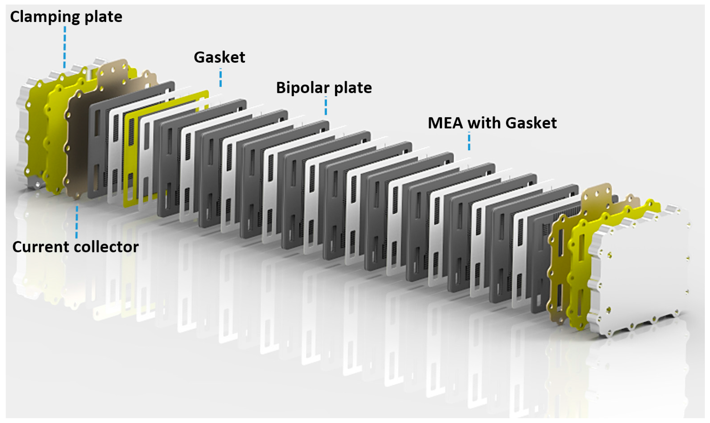
The cost of a fuel cell stack is mainly determined by the cost of membranes, noble-metal catalysts, electrodes, bipolar plates, clamping plates, current collectors, gasket components, peripherals, and assembling processes. A cost analysis should also include investment, labour, and energy costs. It is important to point out that the modular structure of a fuel cell stack is appropriate for automated mass production. This concept is illustrated in
Figure 1, where the DMFC stack configuration developed in a European Community FP7 collaborative FCH JU Project, DURAMET (
www.duramet.eu), is presented in an exploded view.
For an industrial process, it appears clear that the possibility of producing every component separately simplifies the global process of the stack production. The core component of a fuel cell is the membrane-electrode assembly (MEA), which is the assembly of the polymer electrolyte membrane with anode and cathode. Gas diffusion layers (GDLs) and gaskets complete the MEA. Catalysts used for methanol oxidation and oxygen reduction are noble-metal-based catalysts. For this reason, reducing noble metal loadings in MEAs and developing new low-cost membranes have a direct impact on the final cost of a stack. The MEA manufacturing process is another fundamental step to assess mass production. It is necessary to use a technology that can support large-scale production with minimum cost impact and minimum waste of raw materials.
The European project DURAMET focused on the development of durable and cost-effective DMFC components. This work is devoted to the analysis of scaling up the production of a bipolar configuration DMFC stack based on the materials developed in the DURAMET Project.
2. Results and Discussion
2.1. Stack Testing
The modular DMFC stack, which is the object of the present cost analysis, is presented in an exploded view in
Figure 1. This example shows the modular structure of the DMFC fuel cell stack concept. The stack was equipped with electro-catalysts produced at CNR-ITAE (Messina, Italy); bipolar/end plates were designed at CNR-ITAE and manufactured at IRD (Odense, Denmark), membranes were produced at FUMATECH (Bietigheim-Bissingen, Germany), and MEAs were assembled at IRD.
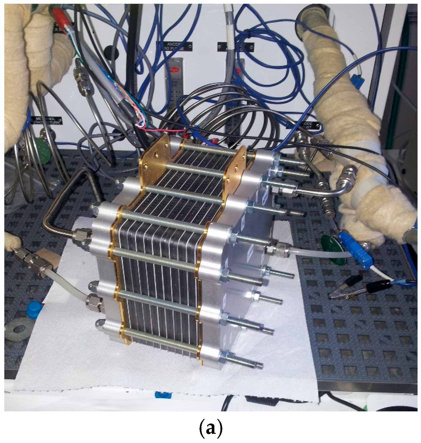
Figure 2a shows the 10-cell DMFC stack under operation at high temperature, ~100 °C, with a pressure of 2 bar
abs and methanol feed concentration of 5 M. Such operating conditions allow a trade-off between performance and energy density. The stack was self-heating due to the heat release from the irreversible electrochemical process at a high current density and as a consequence of methanol crossover, producing chemical recombination with oxygen at the cathode [
1,
2,
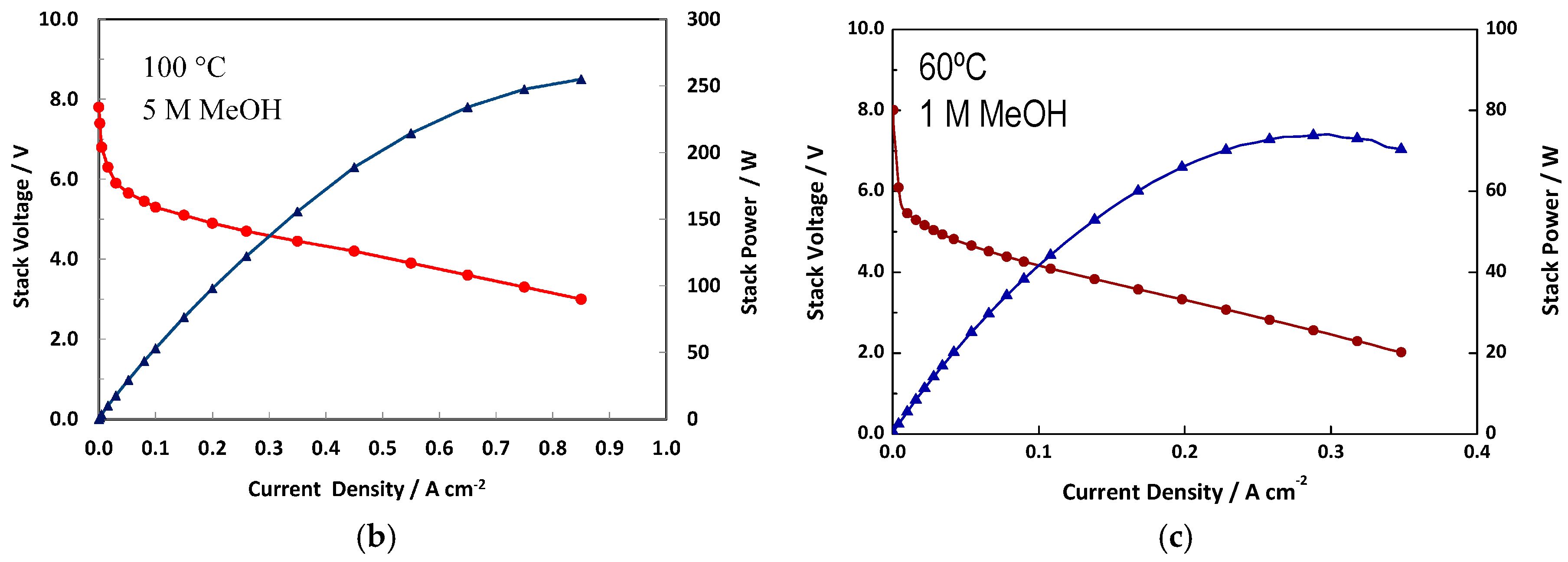
3]. The polarisation curves recorded for the DMFC stack operating at a high temperature and high methanol concentration are reported in
Figure 2b; whereas,
Figure 2c shows the polarisation curves under mild operating conditions (60 °C, 1 M methanol concentration).
At a high temperature (
Figure 2b), it was observed that at an operating current density of 0.5 A·cm
−2, corresponding to a voltage efficiency of practical interest (>35%), a power output of 200 W was achieved, corresponding to an average power density of 200 mW·cm
−2. These operating conditions appear very appropriate for this stack technology. A significantly lower performance was observed at 60 °C with 1 M CH
3OH concentration at ambient pressure (
Figure 2c). The recorded peak power was 75 W in this case, with a specific power density of about 75 mW·cm
−2. It is anticipated that system operation under such mild conditions is associated with a significant increase in the DMFC stack capital costs normalised by the electric power output.
2.2. Economic Analysis of the Stack Production at a Small Scale: Scale-Down Approach
A scale-down approach, focusing on a single fuel cell unit of the stack, was first selected for the study of mass production. The object of this analysis was a DMFC stack of about 200 W peak power output (
Figure 2b) made with innovative laboratory materials. The stack under consideration was composed of 10 cells with 100 cm
2 active area. This analysis is related to a production of 200 units per year. It is pointed out that for a small-scale production, the costs are not significantly different if the number of produced units decreases considerably from the nominal value. For this stack, the estimated laboratory cost of manufacturing a single prototype was €2884. Such costs include manufacturing and energy. The analysis was elaborated to assess in detail all aspects influencing the total cost, with particular attention to the single components of the stack.
Special attention was addressed to the following aspects.
2.2.1. Noble-Metal Catalysts
Catalyst loading is a key factor influencing the system cost on a large-scale production. Significant efforts have been addressed by fuel cell suppliers to reducing the overall content of noble metals in the stack [
6]. Development of new catalysts/electrodes with a low loading of noble metals, or, even better, using efficient noble-metal-free catalysts, could have a high impact on the MEA cost, and therefore on mass production.
Also, the catalyst production method is of relevant importance. A scaled-up production of these materials can reduce the amount of waste material and improve the yield of the process, with environmental and cost benefits.
2.2.2. Membrane
Research efforts on membranes for DMFCs presently include surface treatments to reduce crossover, use of inorganic fillers to improve water uptake and/or dimensional stability, and blending of perfluorosulfonic acid (PFSA) with other polymers [
5]. Development of improved membranes, in particular with lower thickness and lower PFSA ratio than the present ones, e.g., Nafion
®, while maintaining low methanol crossover, can reduce the cost of the single cell. In terms of mass production, this means a considerable cost savings for active materials [
7,
8].
2.2.3. MEA
Regarding the MEA, for small production, a handmade-like assembling process is often used. However, a perspective mass production requires the application of an automated process. This can save time and materials, and will result in a more reproducible process [
9].
2.2.4. Bipolar Plates
Bipolar plates are electric conducting materials and impermeable separators. These are designed to facilitate the mass transport of reactants/products. In particular, these components have a flow field pattern, very often serpentine-like (single or multiple serpentine) to enhance mass transport at high current densities. For small-scale production, bipolar plates are manufactured by machining a nuclear-grade graphite sheet; this process is time-consuming and extremely expensive. There have been tremendous efforts to reduce the cost of bipolar plates by using carbon composites with polymers as a base material, injection moulding of graphite-filled polymer, and metals such as stainless steel or titanium. Bipolar plates play a relevant role because they represent a consistent amount of the total stack cost, especially if the production volume is modest [
10,
11,
12].
2.2.5. Metallic Plates
Clamping plates and current collectors are very expensive in case of small volumes of production. In a scaled-up approach, it is possible to strongly reduce their impact on the total stack cost by using automated industrial processes, e.g., casting, that can bring the single plate cost near to the raw material cost [
12].
2.2.6. Gasketing
The gaskets do not have a strong impact on the total cost, and in a mass production approach automated processes can reduce the cost to nearly that of raw materials.
2.2.7. Additional Hardware Components
Hardware components include bolts, nuts, fittings, tie roads, and washers, which are generally cheap components. From the perspective of industrial-scale production, their cost impact can become almost negligible [
12].
2.2.8. Assembling
For small-scale production this step is by hand and time-consuming [
12]; for mass production it is possible to adopt an automated or semi-automated process in order to save time and energy and reduce the cost accordingly.
The influence of the development of new materials on the cost of a bipolar stack prototype is an important aspect that needs to be properly considered for the feasibility of DMFCs mass production. In the DURAMET Project, for the development of the stack, major efforts were made to improve catalysts and membrane components in order to increase the catalytic activity, reduce the loading of noble metal catalysts, and decrease both the resistance and the thickness of the membrane while avoiding an increase of methanol crossover [
5]. These developments have produced a synergistic effect on the cost reduction. The improvements in DMFC’s technology achieved in DURAMET [
5,
13,
14,
15,
16,
17], at a small production scale, can be summarised as follows:
- (1)
Cost-effective anodic and cathodic catalysts/electrodes manufacturing procedure [
13,
14];
- (2)
Lower noble-metal loading in the catalytic layers (Catalyst-Coated Membrane—CCM) [
13,
14,
15,
16];
- (3)
New low-cost membranes with significantly lower thickness and reduced methanol crossover with respect to the commercial Nafion
® a reference membrane [
5].
However, for mass production of the developed DMFC stacks, there are other aspects beside the MEA, which play an important role. All the components have an influence on the total cost of a single unit produced, and there are several factors that must be taken into consideration.
The materials used for the DURAMET prototype are reported below:
Anode catalyst is a 50% Pt-Ru (1:1)/C [
13,
14,
15]; the metal phase is carbon black supported, with a total noble metal loading of 1.8 mg/cm
2;
Cathode catalyst is based on a 30% Pt/C; the metal phase is carbon black supported, with a Pt loading of 1.2 mg/cm
2 [
16];
Membrane is FUMATECH F1850, 50 µm thickness, with low methanol crossover properties;
Anodic and cathodic GDL layers are used for facilitating the mass transport to the core part of the MEA and easy removal of reaction products;
Bipolar plates are based on composite graphite;
Clamping plates are made in anodized aluminium;
Gold-plated copper current collectors;
Polymeric gaskets;
Bolts, nuts, washers, and fittings.
Table 1 summarises the costs of every single component of the DURAMET stack prototype produced at a small scale (200 units).
2.3. Economic Analysis of Bipolar Stack Production on a Large Scale
In this paragraph, using a scale-down approach and considering in detail every component of the single stack, an industrial process is considered and all aspects that influence mass production are evaluated.
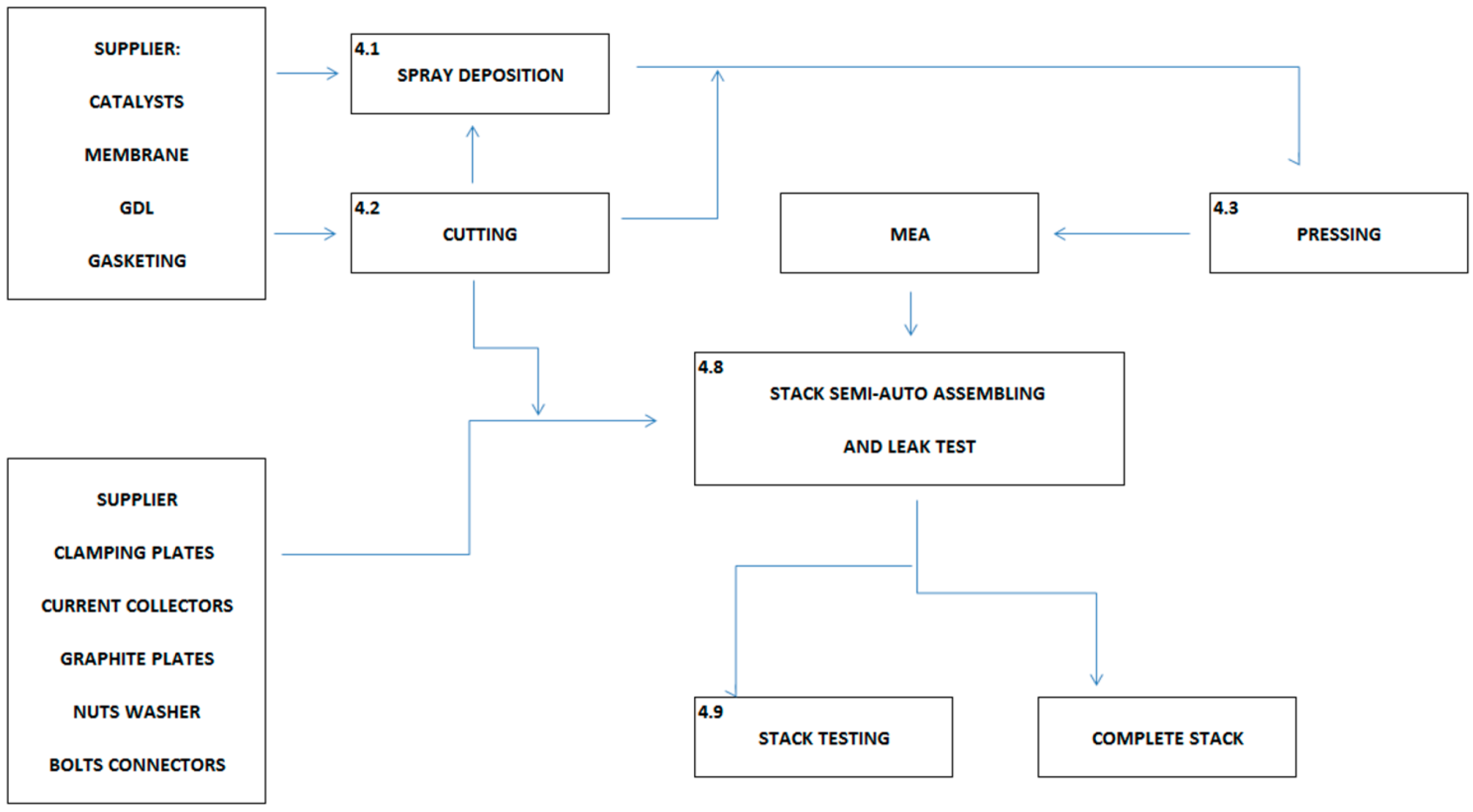
The stack production is configured in different stages according to the modularity of the device. In the first stages, the components are manufactured and thereafter the components are sent for assembling and test procedures.
Figure 3 shows a block diagram for the production of the DMFC stacks. This diagram will be used as a guideline to discuss the mass production. Some hypotheses are made in this analysis. First, the volume of production is fixed at 10,000 units/year, for 250 days of work each year. Eight hours per day of effective work are assumed; this results in 40 units per day, corresponding to five units every hour. This volume is still limited because some factors, like market request, which has not been evaluated in this work, indicate that DMFC technology will not have a wide impact immediately; furthermore, this technology is a high-tech product and therefore it is not realistic to imagine high production volumes immediately.
In summary, the hypotheses are:
To simplify the factory scheme and the analysis of the stack manufacturing aspects, it is supposed that this is mostly entirely produced starting from raw materials and then it is possible to distinguish between internal and external processes:
External processes:
Raw materials and hardware production;
Bipolar plates production;
Metallic plates production.
The fixed volume of production does not allow a clear estimation of the production level for plates starting directly from raw materials. Some hardware characteristics are presented below:
Clamping plates are made of Al alloy EN-AW6082;
Current collectors are made of Cu gold plated DHP EN 12165;
Bipolar plates are made of composite graphite;
Additional hardware components for stack assembling are nuts, bolts, and fittings.
The production of the stack is carried out in different stages, as shown in
Figure 3.
2.4. Production of Catalyst-Coated Membrane Core Components
The active part of a DMFC is the MEA, where chemical reactions producing electrical energy take place. The MEA is composed by a polymeric membrane, which allows the protons to cross from anode to cathode, where anodic and cathodic catalytic layers are coated onto the membrane. The catalysts used in this application are currently noble-metal-based because of the acidic environment produced by proton exchange membrane. In the industrial scheme considered here, a spray-coating technique is selected since it provides accurate deposition of the catalysts on a fixed membrane area, using a solution containing the catalyst dispersion. A fixed flow regulated by a nozzle of a specific size is used. This process includes a stage of deposition on the two different sides of a membrane roll of cathodic and anodic layers with a stage of drying. Considering the fact that the nozzle allows for a wide range of flows, it is possible to adopt a strategy whereby a highly concentrated dispersion of catalyst is used with a high flow of gas carrier in order to allow a rapid drying of the catalyst deposited onto the membrane. This also allows for precise and reproducible mass loading for the catalysts deposited by spray-coating without significant time consumption.
2.5. Intermediate Cutting Stage
This stage is common to a wide number of components forming the core part of the stack, excluding catalysts powder and plates. For the stack assembling, the MEA is supplied in a roll form and then is cut for assembling the single cells. A die cutter is used, with different cycles for the different materials. It is important to observe that the commercial die cutters can work at a very high speed and thus the cutting process does not slow down the entire production process. The CCM obtained from the spray-coater/drying apparatus is thus cut to the final size designed for the MEAs.
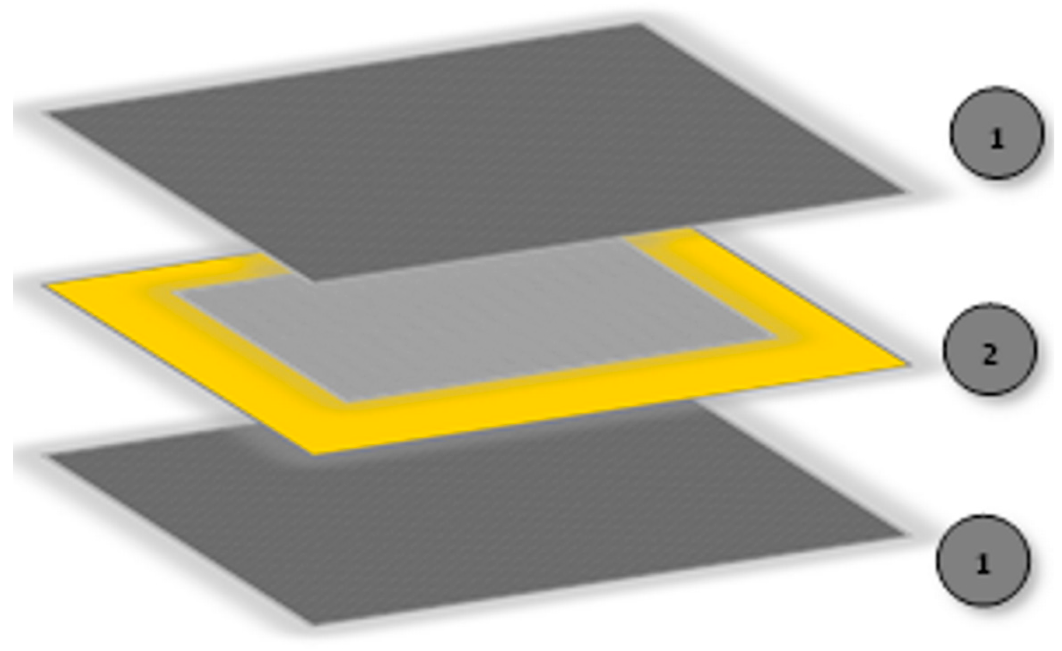
2.6. Membrane-Electrode Assembly Hot Pressing
MEAs include another two components, beside the CCMs, to form the single cell units. These are the GDLs and the gaskets, as shown in
Figure 4.
The GDL is a porous medium composed of a woven or non-woven array of carbon fibres. The GDL plays an important role in connecting electronically bipolar plates and electrodes. Moreover, a critical function of a GDL is to facilitate reactant transport to the catalytic layer and heat/product removal (water at the cathode and CO2 at the anode). It also serves as a mechanical support for the MEA.
Gaskets are employed to seal the MEAs and have an important impact on some steps of the stack production process because they allow a proper clamping and alignment with the stack plates. After the CCM is cut in the die cutter, single CCMs are ready to be used for preparing MEAs. GDLs and PTFE-like gaskets are also cut to the correct shape. These components (CCMs, GDLs, and gaskets) are sent to the hot-press procedure, where every single MEA is laminated. This step is carried out according to a specific protocol, which includes heating at a specific ramp rate in order to achieve a temperature close to the glass transition temperature of the membrane. The MEA is thus kept under pressure at this specific temperature to facilitate the formation of a stable interface between the membrane and the catalytic layers as well as between catalytic layers and GDLs.
The hot-pressing is the slowest step of the entire industrial process, and several machines are required. The slowness of this stage is essentially due to the time required for hot/cold cycles of the press (in order to avoid non-homogenous swelling and occurrence of cracks in the catalytic layers, this process needs to be carried out with a slow temperature ramp rate). The MEA layers need to be hot-pressed for at least 2–4 min at the maximum temperature to form good interfaces.
In the
Section 2.13, we will discuss how this influences the production and how we can optimize the single MEA production time.
2.7. Bipolar Plates
The assumed volume of production is not large enough at the moment to justify the production of every single component starting from raw materials. Some of the plates of the stack cannot be produced directly in the process plant designed in
Figure 3 because, for this kind of component, it is necessary to have a set of equipment that requires a very large initial investment. An initial mass production of 10,000 units/year cannot permit a return on this investment. Currently, DMFCs technology has no such wide market diffusion. Internal production is restricted to components playing a relevant role in the electrochemical process.
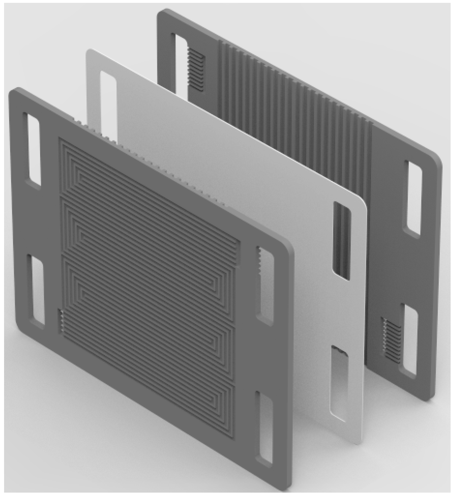
The bipolar plate is a critical component playing different functions in the DMFC stack (
Figure 5). It connects electrically in series the single cells while avoiding the mixing of reactants in two adjacent electrode compartments. A bipolar plate is generally equipped, on the external faces, with a machined or stamped flow-field that allows for efficient distribution of the reactants over the electrode and facilitates product removal. The bipolar plate also acts as a mechanical support for the MEA and allows for uniform distribution of the applied clamping force during stack assembly. Generally, another flow field with a different design is machined on the inner face to form the cooling section that can be fed by a cooling fluid or, in the specific case of the DURAMET DMFC stack, is exposed to the cooling action of natural air convection. This is made possible if the methanol solution fed to the anode is used besides the reactant as an internal cooling fluid. For a high power stack operating at temperatures lower than 80 °C, it is preferable to use a specific liquid coolant. If the DMFC membrane allows for an extension of the operating temperature range, e.g., up to 100 °C, with a small backup pressure, the methanol solution can be used for efficient stack temperature control.
The manufacture of bipolar plate components would preferably be based on a cost-effective injection moulding technology using composite graphite as the base material. A mixture of graphite and polymer is prepared and then injected into a mould that has the specific shape of the plates. Usually, there are three different shapes for the bipolar plates in a stack. There is a specific design for the plates between the MEAs, another design for the bottom plate, and a third one for the top plate. Once manufactured separately, bipolar plates are used directly in the self-automated assembling process presented in the production scheme above.
2.8. Clamping Plates
Clamping plates are needed at both ends of the stack to apply pressure on the cells, maintain the structure, and prevent the fuel and gas from escaping from between the plates. The end plates would have holes for the bolts as well as for the inlet and outlet manifolds. For the stack adopted in this analysis, the clamping plates are made of an anodized aluminium alloy and the same assumptions made for the bipolar plates are valid. The clamping plate is made by casting technology and the aluminium alloy is molten and then cast into a mould of the desired shape; after this, there is the anodizing procedure, which for mass production does not influence the cost of the raw material.
2.9. Current Collectors
The terminal current collectors are responsible for the collection of the electrical current generated by the device and then serve to close the overall circuit. For this specific DMFC stack, this component is made of gold-plated copper to maximise conductivity and avoid corrosion caused by the hot methanol solution and humidified air. Studies should address the creation of cheaper, corrosion-resistant current collection plates. The technique adopted for the production is casting, like for the clamping plates, followed by gold plating, which is made with sputtering or electrochemical bath techniques. A gold layer thickness of 50 nm is used. The cost of gold coating is already added into the estimation of the cost of raw components for fabricating the current collection plates.
2.10. Assembling Process
After the MEA production, the stack is assembled through an assembling station with an integrated leak test setup. Plates, MEAs and gasketing components are assembled and pressed together; thereafter, the stack is assembled with bolts, nuts, and washers at a specific tightening torque; also, the fittings are assembled in this step. After the stack is totally assembled, it is possible to make a leak test with N2 in order to see if the assembling process was done correctly. If there is a positive leak test, the stack is ready for conditioning and further characterisation.
2.11. Stack Testing
To commercialize a high-tech product, it is necessary to do preliminary sample testing, very likely on a statistical basis, in order to evaluate the quality of the production. One stack per day can be randomly sampled as a representative of the production of the day, and tested at a specific test station. The parameters that have to be controlled are: temperature, pressure, gas and fuel flow rates, humidity, voltage, current, and stack power.
2.12. Cost Estimates
An important step of this analysis is the evaluation of the cost of raw materials.
Table 2 shows a detailed list of materials used for stack production; the data for the scale-down approach refer to a single unit.
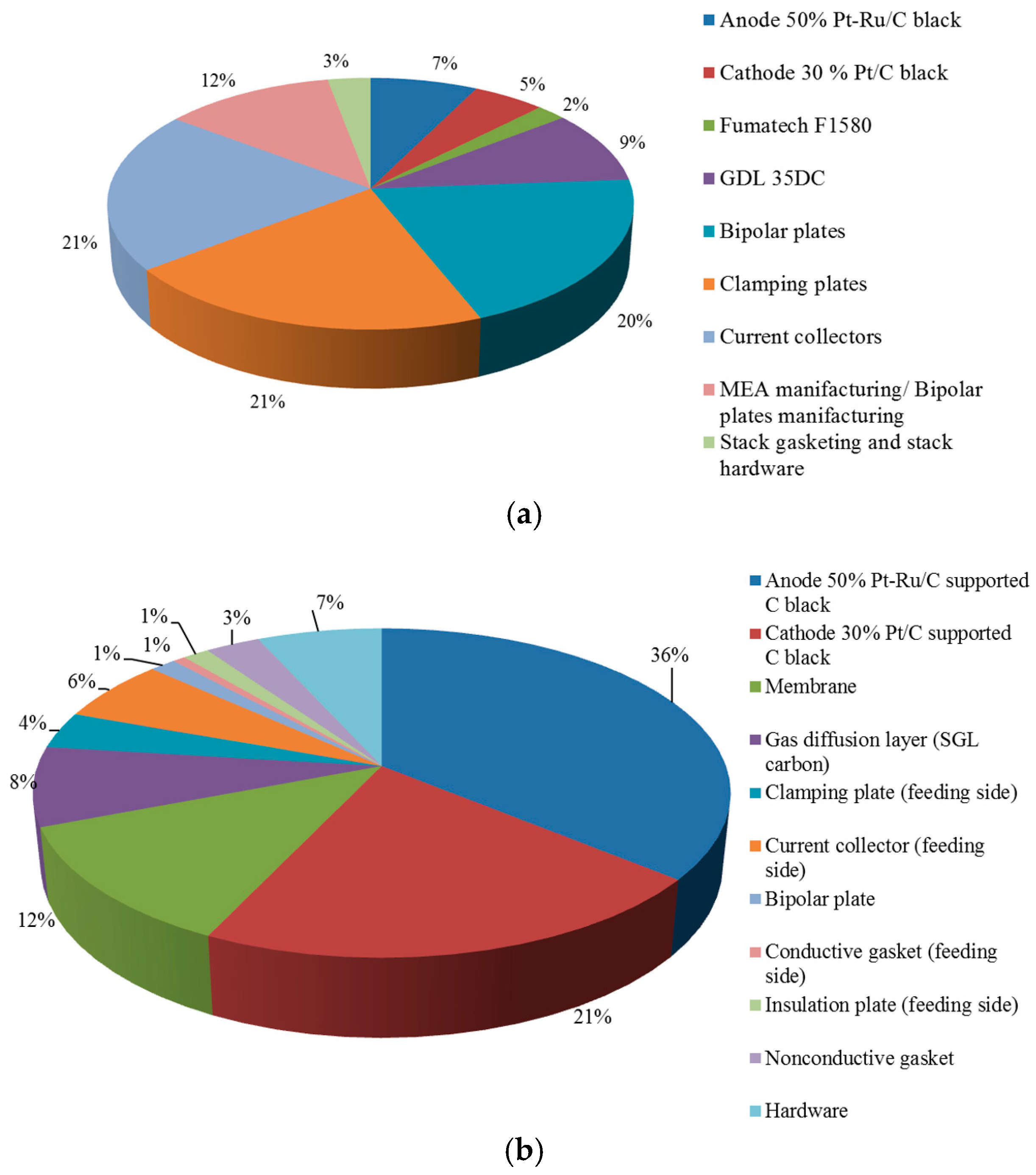
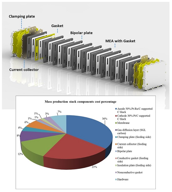
Two pie charts are reported (
Figure 6) for the cost percentage referring to a single unit manufactured both at a small scale and via mass production. For small-scale production, MEA materials make the MEA impact on total cost relatively low, nearly 20% of the total. All the components like plates and related manufacturing are very expensive. This is because, at this level of production, some components are manufactured using machining techniques, which are expensive and time-consuming. The waste material and the overall cost of manufacturing strongly influence the cost of a single prototype.
At a scaled-up production level, the situation becomes completely different. All plates, Al, gold-coated Cu, and graphite, are characterised by an enormous reduction of cost at this level. This is because, with an industrial production methodology of these components, the cost is near the market cost of raw materials. Regarding manufacturing and waste, an industrial process can optimize the stack production, breaking down the cost for manufacturing and strongly limiting the waste of materials. All gasketing components have a low impact because a small amount of raw material is used. Regarding the MEA, at a scaled-up level, we have a totally different situation. Now, looking at the single unit, the catalysts have a larger impact on the overall cost. This is essentially due to the high cost of the noble metals.
For this reason, the reduction of noble-metal loading, and possibly the replacement of noble metals with cheaper catalyst alternatives [
18,
19], may have a large impact on the device cost in the case of large-scale production.
However, in cases where the noble-metal catalysts cannot be replaced with cost-effective alternatives, there is a large cost saving for the catalysts in the case of mass production. The same holds for the membrane. A membrane is a special chemical product and its contribution to the cost of a single unit is higher in the case of a small production scale but not comparable to the cost of plates.
Comparing the two production scales, we have some marked differences that can be discussed in detail:
Catalysts were synthesised and quoted by a DURAMET partner at prototype level, while for the scale-up, production synthesis and a quotation were supplied by a leading company in the field. From the pie charts, a strong difference in the cost impact of these components is evident for small- and large-scale production. At a small scale of production, the lower impact is due to the improvements conferred by the new materials (a reduction of noble metal loading), whereas the cost of stack plates remains high due to the machining procedure widely used for small production. The higher impact in the case of scaled-up production should be analysed in view of the fact that the cost of the other components strongly decreases due to the impact of mass production on the total cost, e.g., stamped bipolar plates production instead of mechanical machining of flow fields. In an ideal situation, the noble-metal-based catalysts are the most expensive components in the stack and this can only be modified if noble-metal-free catalysts providing similar performance and stability are used.
This component was synthesised by a partner of the DURAMET consortium during the project, and the mass production was already envisaged. The two fundamental improvements that allow for a decrease in the membrane cost are the reduction of the thickness and the replacement of PFSA with a cheaper polymer [
5]. Similarly to the catalysts, the cost impact of the membrane decreases when passing from a small volume to scaled-up production. The replacement of PFSA membranes with cost-effective membranes, e.g., hydrocarbon-type [
5], also has a strong impact. The net cost of the component is strongly reduced, but the higher impact at scaled-up production is due to the fact that this is a fine chemical product, and its final cost cannot be lower than the raw material cost. This is very high for PFSA polymers since fluorine chemistry is involved.
The quotation for these components was given by a leading manufacturer of this kind of material. As shown in the pie charts, their cost percentage is the same for both volumes of production assumed here. This means that the net cost of this component is proportionally reduced for high production volumes. This is due to the nature of raw materials, which are not as expensive as catalysts because they are essentially based on carbon fibres. However, it is not reducible to raw material cost because the manufacturing process involves the production of carbon fibres.
The quotation of these components was obtained by a partner of the project for prototype and scale-up evaluation. Gaskets have some impact on the total cost when scaled-up production is considered. This kind of material is already near the material cost at a small production volume. Gaskets are polymeric materials manufactured in the form of rolls. The impact of these gasketing components on the total cost becomes higher with the production because the relative saving is very low with respect to other components. However, the net cost is reduced for the mass production.
As shown in the pie charts, the cost percentage of these components for small-scale production is very significant. The cost percentage for each type of plate varies with the change in production scale. In detail:
- (1)
Al plates: cost impact decreases from 20% to 4% of the total cost;
- (2)
Cu plates: cost impact decreases pass from 20% to 6% of the total cost;
- (3)
Graphite plates: cost impact decreases pass from 20% to 1% of the total cost.
The variation of the cost of plates with different mass production scale is due to the different manufacturing procedures because, at a large scale, the cost of the components approaches the raw material cost. The quotation was obtained by a project partner, who has developed and manufactured the plates for the prototype; moreover, for mass production the quotation was given by a company specialising in the manufacturing of these materials.
The quotation for these components was given by a specialised company, taking into account the production scale. A flat rate is considered for the single stack assembled. The net cost of these stack elements is reduced, but the percentage of the total cost is larger. The explanation is similar to that provided for the gasketing components. There is a cost saving, but it is less significant than for other components.
A summary of the net cost of components for a single stack produced on a mass scale is given in
Table 2. As discussed above, the components that produce the main impact on the cost of the DMFC stack in large-scale production are essentially the catalysts because of the large cost of raw materials. If the mass loading of the noble metal catalysts in the electrode decreases by at least one order of magnitude or the noble metals are replaced by equally performing and stable cost-effective electrodes, as strongly recommended by recent research efforts [
18,
19], the membrane would become the most expensive component. In this regard, similar developments regarding new polymer electrolyte membranes with high ionic conductivity, stability, and low permeability characteristics similar to the present perfluorosulfonic acid membranes are also needed.
If production is at an intermediate scale, between the large and small scales considered here—as an example, if the application of DMFC systems essentially targets one or two limited sectors such as power supply for telecommunications and APU for campers—the most expensive components would still be the catalysts and the membrane. However, lower impact with respect to the estimates made on a large scale is expected.
2.13. Investments
At the prototype level, it is difficult to separate the contribution of the cost of a single component in different factors like material, labour, and energy costs. On the other hand, mass production has to take into account many other factors beyond the raw materials: labour costs, energy consumption, and investments; these aspects need to be carefully evaluated.
In
Table 3, the investments for the production processes, both internal and external, are estimated. For internal processes, the first kind of investment regards the machinery. The components, manufactured internally, are produced starting from raw materials. In
Table 3, the machineries required for each stage of production are reported. The analysis was performed by taking into account the requirements of the total process, such as the optimization of workers’ time with consequent energy savings in an optimised overall process.
The block diagram in
Figure 3 shows the different stages of stack production. The only kind of machinery that is not unitary in this scheme is the MEA assembling press. Since the MEA component assembly takes about three minutes, this makes this step the slowest one in the overall production process. Hot pressing appears at the moment to be the most appropriate approach to forming an efficient backing layer-catalyst layer-membrane interface. This may be replaced by an equivalently efficient but faster process. To fulfil the production requirements, three hot presses are required in a production line. This bottleneck associated with MEA production implies the use of more machines and thus a larger investment.
At present, the total investment in these machines for internal production is estimated to be around €511,000.
Regarding the stack plates, direct machining [
20] was compared with injection moulding for graphite and with casting for metals.
Table 4 compares the costs for production of stack plates.
Injection moulding is the best approach for graphite; a cost of €60,000 for the mould was assumed, and because one mould can guarantee 20,000 pieces, 20 moulds are required (the number of graphite plates in the designed APU stack is 20). The same assertion can be made for the casting process of metallic plates. The cost is a total of €60,000 for four moulds.
“Machining would require about €10 for every plate” (Direct quotation from supplier). This turned out to be inadequate for mass production. By selecting casting or moulding, the total investment for external processes (plates) and for proper machinery is €2 million, which means €100 for a single unit, which in comparison to the cost of MEA appears relatively low and thus acceptable.
Other aspects to be considered are the energy consumption and the labour cost for each produced unit. Average values were determined using data relative to European countries [
21]; the electric energy cost was €1/stack and the cost of labour was €29/stack.
The production process requires seven labourers per production line in order to sustain the entire process. The volume of production can be five stacks per hour, and because the average labour cost is €21 per hour, the impact of labour cost per single stack is calculated to be €29. On the other hand, the energy consumption was calculated on the basis of data from processing plants and is equal to 10 kWh per set of production, corresponding to €1 per stack.
2.14. Amortization and Profits
The DMFC can provide a power output of 0.2 kW at an estimated cost of €1650/kW. The total cost of a single unit (€331) was calculated by adding: the total cost of raw material for the components (€223, see
Table 2), the cost for plates production by casting plus moulding (€72), the cost for the electric power (€1), the labour (€29) and the cost for the maintenance (€6) The cost of machinery replacement was not considered because a durability of about 14 years was assumed, equivalent to seven cycles of production (20,000 units per cycle). However, a maintenance percentage for the machinery of 10% per year was considered; this corresponds to a cost of €6 per stack. In this analysis, it is assumed that the initial capital investment, for the production of the first 10,000 stacks and the machinery, is given by a bank, and interest is applied to the loan. Three percent interest on the loan was assumed [
21] in the worst case, with a time for return of loan of two years that is equal in length to the first production cycle (20,000 units). In order to make a profit, the stack price is fixed at €400 (20% plus the stack cost). These costs are related to the operation at 100 °C and with 5 M methanol. When the system is operated at a lower temperature (60 °C) and with lower methanol concentration (1 M), the stack cost increases to €1666. Thus, operation under mild conditions causes a considerable increase in capital costs.
The cost of a state-of-the-art APU unit based on an internal combustion engine is currently about €4500/kW [
22,
23], whereas the APU stack based on the DMFC technology would cost €1650/kW according to the present cost analysis. However, this cost does not include the balance of plant, which may contribute up to about 50% of the total cost [
2]. Thus, the overall estimation would give a cost of less than €4000/kW for the DMFC system, which is competitive or similar to that of a competing technology characterised by significantly higher environmental impact.
The power density per unit of weight and volume of the present stack prototype are about 50 W/kg and 70 W/L, respectively. However, it is considered that the components that mainly contribute to determining such values in a short stack are essentially the end plates (~50%). In principle, these plates can handle a much larger number of cells (several hundreds). Thus, a large DMFC stack using the same components could reach, in principle, power densities of 100 W/kg or 100 W/L. In a balance of plant, the stack is coupled to a pure methanol tank providing energy densities of 4.82 kWh/L and 6.1 kWh/kg.
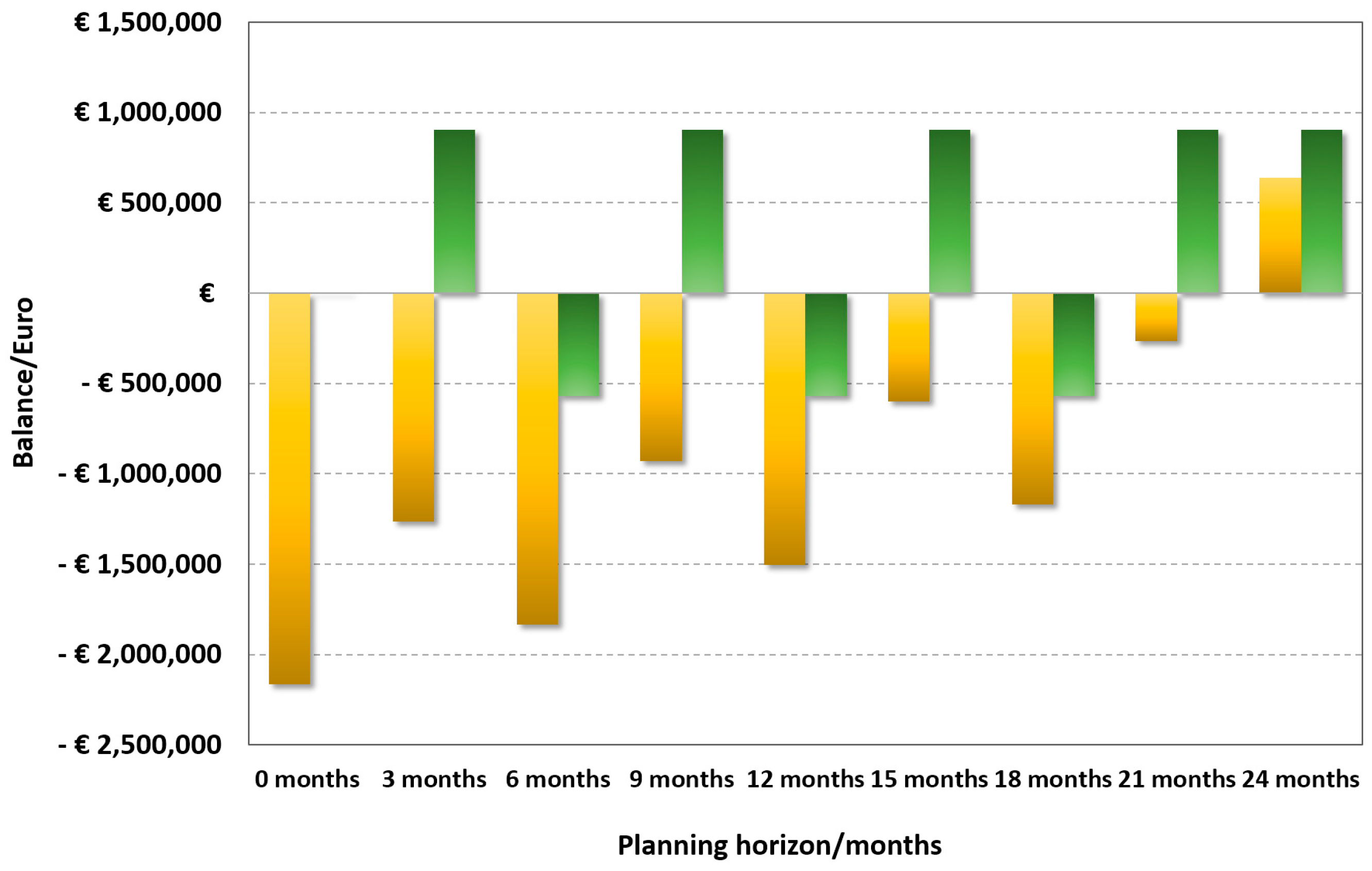
Table 5 reports the data for a complete industrial investment and profit outline.
Figure 7 shows the economic trends of investment and profit for mass production of DMFC stacks. It is observed that there is a significant investment in the first three months, which strongly affects the payback time. This is expected to be achieved after 24 months. Assuming that the duration of the production line covers a lifespan of 20 years, with small modifications in due course, there is in any case a significant return on the investment and capital gain. However, a financial model including economic incentives to cover the initial investment appears to be necessary to support this economic activity, especially if it is undertaken by a small to medium enterprise.
It is worth noting that, considering the expenses for all cycles of production, if all the stacks are sold there is an appropriate capital return and a gain. That will allow the producer to buy another set of machinery and the raw materials, and cover the external expenses for plates. This means that it is possible to expand the production or that, for the next cycles of production, the gain is assured. This will increase because there are no expenses for new machinery and to cover the interest. These numbers show the feasibility of mass production of the DMFC stack. Such figures could be further refined with a detailed analysis of the costs of the raw materials; however, no significant deviation is expected from the estimated costs.
As discussed above, a significant cost saving can be achieved by replacing noble-metal catalysts with cost-effective materials or significantly decreasing the mass loading of platinum group metals (PGM), replacing perfluorosulfonate ionomers with cheaper hydrocarbon membranes, and using injection moulding/casting for bipolar plate production in place of machining processes.


 ,
, 


