Article

Research on a Household Dual Heat Source Heat Pump Water Heater with Preheater Based on ASPEN PLUS

School of Energy and Environmental Engineering, Hebei University of Technology, 5340# Xiping Road, Shuangkou Town, Beichen District, Tianjin 300401, China
*
Author to whom correspondence should be addressed.
Energies 2016, 9(12), 1026; https://doi.org/10.3390/en9121026
Submission received: 6 October 2016 / Revised: 31 October 2016 / Accepted: 25 November 2016 / Published: 3 December 2016
(This article belongs to the Special Issue Advanced Heating and Cooling Techniques)

Abstract

:
This article proposes a dual heat source heat pump bathroom unit with preheater which is feasible for a single family. The system effectively integrates the air source heat pump (ASHP) and wastewater source heat pump (WSHP) technologies, and incorporates a preheater to recover shower wastewater heat and thus improve the total coefficient of performance (COP) of the system, and it has no electric auxiliary heating device, which is favorable to improve the security of the system operation. The process simulation software ASPEN PLUS, widely used in the design and optimization of thermodynamic systems, was used to simulate various cases of system use and to analyze the impact of the preheater on the system. The average COP value of a system with preheater is 6.588 and without preheater it is 4.677. Based on the optimization and analysis, under the standard conditions of air at 25 °C, relative humidity of 70%, wastewater at 35 °C, wastewater flow rate of 0.07 kg/s, tap water at 15 °C, and condenser outlet water temperature at 50 °C, the theoretical COP of the system can reach 9.784 at an evaporating temperature of 14.96 °C, condensing temperature of 48.74 °C, and preheated water temperature of 27.19 °C.

Graphical Abstract

1. Introduction

Along with the increasingly serious environmental pollution and scarce resources, people have paid more and more attention to energy conservation and emissions reduction [1,2]. A heat pump (HP) can use some amount of external power to move thermal energy from a heat source (air, wastewater, ground, underground water, etc.) to a warmer destination (hot air, hot water, etc.) called a “heat sink”. Various forms of heat pump (HP) technology have been gradually popularized in recent years, such as air source heat pump (ASHP) technology (extracting heat from air), wastewater source heat pump (WSHP) technology (extracting heat from wastewater), ground source heat pump (GSHP) technology (extracting heat from ground) [3] and underground water source heat pump (UWSHP) technology (extracting heat from underground water) [4]. Among all these heat pump technologies, ASHP and WSHP technologies play an important role [5].
ASHP technology is being used by many families nowadays and there also exist a wide range of applications in industry. It is also widely used in the areas having warm climates where the evaporator of an ASHP water heater is generally installed as an outdoor heat exchanger. It absorbs heat from the outdoor atmosphere to heat the cold water used for household and industry. However, if the outdoor environmental temperature is less, the system operation becomes neither efficient nor reliable or stable [6,7]. Several scholars have conducted a lot of research to address its disadvantages, and obtained the solution in the form of certain advanced techniques such as heat pump systems coupled with ejectors and economized vapor injection scroll compressors [8,9], two-stage compression heat pump systems [10,11], cascade heat pump systems [12,13], heat pump systems with alternative working fluids [14,15,16], heat pump systems using phase change material [17,18,19] and heat pump systems coupled with other energy sources [20,21,22,23], but these advancements increase system complexity and the overheads incurred in the system manufacture, operation and control. Therefore, these solutions are usually not advisable for household heat pump systems.
WSHP research focuses on large scale centralized users, such as communities, hotels and bath centers. WSHP is better than an ASHP since wastewater is less affected by climate, season and environmental temperature. Furthermore, its temperature is relatively stable during runtime and the reliability of the system is improved. However, there also exist the disadvantages of clogging and scaling. Currently, there are a lot of studies engaged in solving these problems, and to some extent, these problems related to WSHPs have been solved. Thus, studies on making WSHP systems using small-sized and domestic shower wastewater are reported [24,25,26]. Kahraman et al. [27] proposed a WSHP water heater system. They used immersion tanks to design the wastewater source evaporator and the condenser. The coefficient of performance (COP) of the system rose as the temperature of wastewater increased, whereby for the heat source temperatures of 20 °C, 30 °C and 40 °C, the COPs of the system became 3.36, 3.43 and 3.69, respectively. Besides, as the temperature of the cold water to be heated rose, the condensing pressure increased. At the same time, the evaporating pressure was almost invariable, thus heating capacity and COP decreased. Wong et al. [28] proposed a shower water heat source heat pump water heater system for high-rise residential buildings. The condenser of the system is a directly-heated type. They analyzed the effects of shower running time, shower wastewater flow rate and structure of heat exchangers on the system energy saving effect. The feasibility and the energy saving properties were verified through their experiments. Liu et al. [29] proposed a system based upon WSHP technology for public shower facilities. The system was based on an absorption heat pump cycle and a preheater was added. They introduced the components and control process of the system. The economics and energy-saving effect of the system was compared with traditional electric heat pump (TEHP) systems. The COP of the system was 3.26 under the design conditions and the highest COP of the system recorded during runtime was 5.76. They found that the heat recovery system using a direct-fired absorption heat pump had lower energy consumption, less pollution, lower operating cost, and shorter payback period. Chen et al. [30] proposed a heat pump (HP) water heater for bathing, to which shower wastewater was added and could supply hot water in a few minutes. The regenerator and the wastewater source evaporator were separated. A thermodynamic system comprised of both static and dynamic models was developed, and the corresponding numerical simulations were conducted. The optimal COP of the whole system reached 4.97 as the condensing and evaporating temperatures were optimized at 51.50 °C and 11.68 °C, respectively. The simulation results provided good guidelines for the further design and optimization of the system. Dong et al. [31] proposed a novel HP water heater assisted with shower drain water designed for a small family. A shower waste heat extraction device with water preheated loops was designed to improve its performance, but this system was assisted by a single heat source and an electric auxiliary heating device was added. The experimental results revealed that about 70% of energy could be conserved by using this novel HP water heater, compared with that of the traditional electric water heater.
Scholars have conducted relatively less research on the combination of air source and wastewater source heat pump technology. The objects of their studies were focused on large centralized sites, and some of them were assisted with other energy sources, such as solar energy and ground heat sources. Chen et al. [32] proposed an AWDSHP water heater for heat recovery. The heat pump system could heat water by using a single air source, a single water source, or air-water dual sources. The results of analysis and experiments showed that COP of the device can reach up to 4–5.5 in winter, twice as much as of an air source heat pump (ASHP) water heater. The utilization of waste heat in the proposed system was more than that in the system comprised only of wastewater as heat or preheating source. The energy saving effect of the new system was obvious. Zhang et al. [33,34] proposed an air-water dual source compound heat exchanger in a solar-air dual source compound heat pump (SADSCHP) system. The air-water dual source compound heat exchanger was used as the evaporator of the heat pump system, and it was the key component. The evaporator made three kinds of working fluid exchange heat synchronously. The mathematical model of the solar-air dual source compound heat pump (SADSCHP) system was established. The mathematical simulation method has been used to study the effect of the structure parameters of air-water dual source compound heat exchanger on the energy saving efficiency of the SADSCHP system, and the optimization scheme of the structure parameters under the simulating condition was determined.
Air source and wastewater source heat pump technologies have been widely studied. However, the organic combination of both technologies lacks meaningful exploration. Therefore, this article proposes a dual heat source heat pump bathroom unit with preheater, which is suitable for a family to use, and the process simulation software ASPEN PLUS was used to simulate and analyze the system.

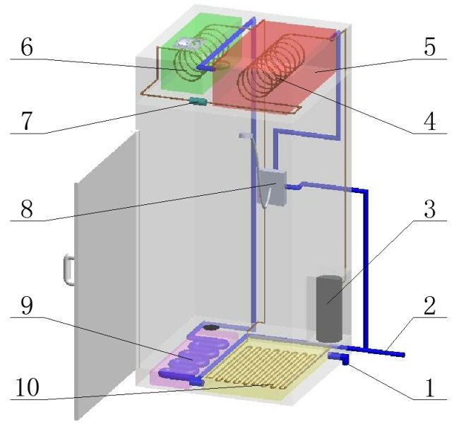
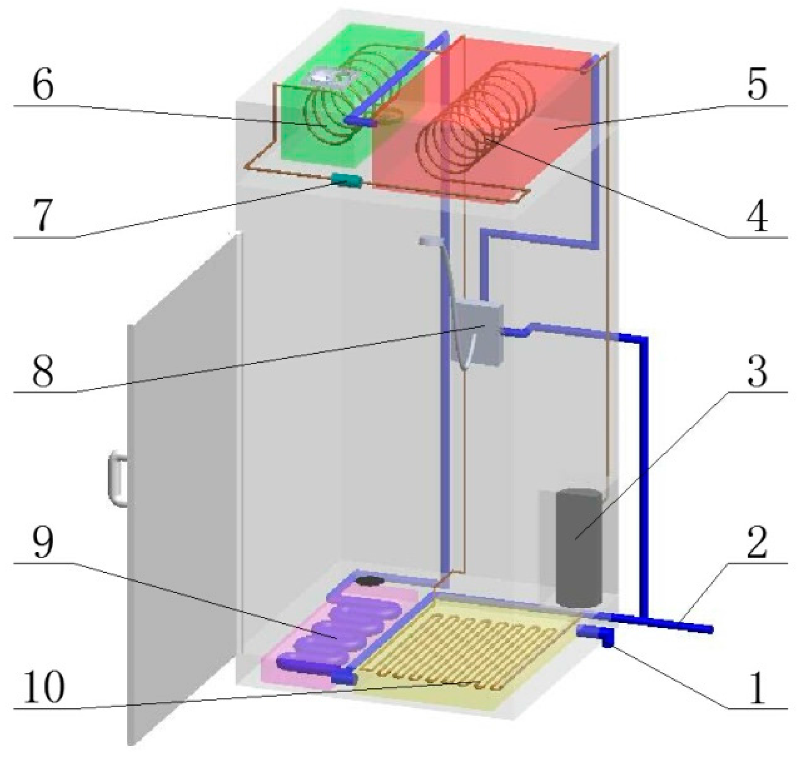
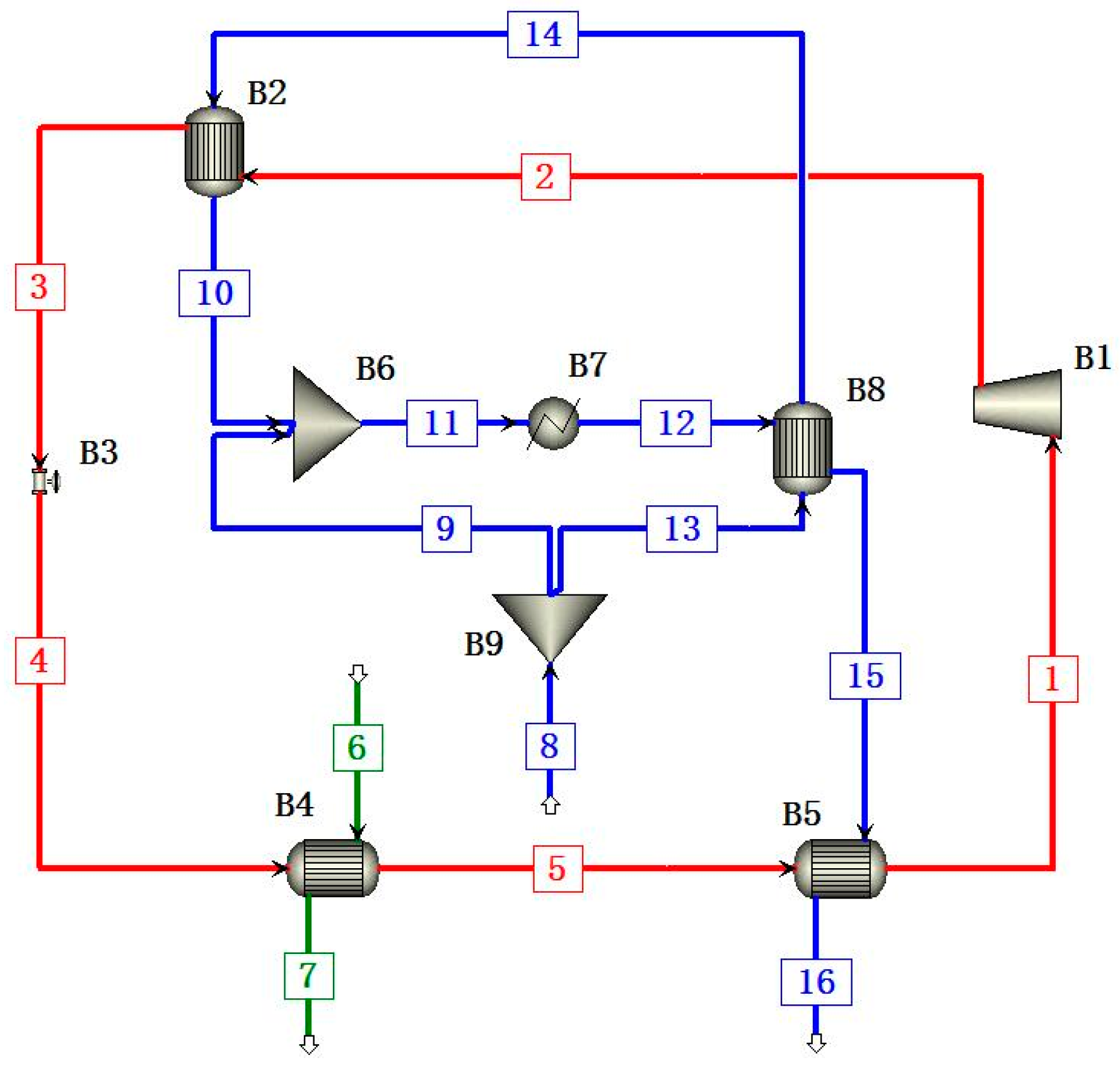
2. Characteristics of the System

As shown in Figure 1, the air source evaporator, expansion valve, condenser and water tank are located in the top space. The compressor, water mixer and control system are in the middle. The preheater and wastewater source evaporator are in the bottom space. R134a is used as working fluid in the system. The system integrates air source heat pump (ASHP) technology and wastewater source heat pump (WSHP) technology, making full use of the heat of humid air and shower wastewater in the bathroom unit.
Prior to the shower wastewater being used in the heat pump system, the system preheater absorbs part of the wastewater heat to heat the cold water. This way it can recover the shower wastewater heat, and thus improve the total COP of the system. The condenser is an immersed heat exchanger. The air source evaporator is an indoor unit and it absorbs the heat of the humid air in the bathroom unit. A lot of water vapor is released to the air during a shower, which eventually enriches the relative humidity in the bathroom unit. The heat pump system can make full use of the latent heat of vaporization of humid air. The wastewater source evaporator is in the bottom space and it absorbs the heat of shower wastewater. The system can avoid the effects of the climate and environmental temperature. Furthermore, it does not need an electric auxiliary heating device and completely realizes the separation of water and electricity. This method improves the reliability and security of the system operation and reduces the system manufacturing and operation cost. When the system starts up for the first time or in the process of heat preservation after taking a shower, the automatic control system turns the wastewater source evaporator off and turns the air source evaporator on to heat water to specified temperature for taking a shower. In the process of bathing, the air source evaporator and wastewater source evaporator take part simultaneously in providing hot water continuously. ASPEN PLUS has been used to simulate the operation parameters under different working conditions in the shower process of the system, and the impact of the preheater on the total COP value of the system is analyzed. Comparisons of the system energy saving effect under different working conditions with and without preheater are presented.

3. Establishment of the Simulation Process

ASPEN PLUS is a large scale general process simulation software with a huge physical property database mostly used in the chemical industry field. This software has an integrated structure and includes process-related unit operation modules besides components, properties and state equations. Every segment of heat pump system is designated the corresponding module. The field of chemical industry which ASPEN PLUS is concentrating on and the field of heat pump and refrigeration have common theoretical bases on the fundamental equation of states, transfer equation and constitutive equation of matters [35,36,37].

3.1. The State and Property of the Matter in the Simulation Process

During simulation with ASPEN PLUS, the physical property methods adopted have been selected according to their corresponding matters such as for the R134a working fluid, the Peng Robinson (PR) property method was chosen. Similarly, IDEAL and STEAM-TA property methods were engaged for dry air contained in humid air and pure water & steam, respectively. These property methods are described below.

3.1.1. The Peng-Robinson Property Method

Peng Robinson (PR) equation is a dual parameter equation as well as a modified version of the Redlich-Kwang (RK) equation. It was proposed by Peng-Robinson in 1976 [38]. However, there are some shortcomings in RK equation that are not resolved by using the PR equation; such as the fact that it fails to generate satisfactory density values for a liquid even if the calculated vapor densities were generally accepted. The empirical form of the PR equation is:
p = RT v b a v ( v + b ) + b ( v b )
in which, b = 0 . 07780 RT c p c ; a = a ( T c ) α ; a ( T c ) = 0 . 45724 R 2 T re 2 p c ;   α 0 . 5 = 1 + ak ( 1 T re 0 . 5 ) ; ak = 0 . 37464 + 1 . 54226 ω 0 . 26992   ω 2 ; T re = T / T c . The PR equation can be rewritten as:
Z 3 ( 1 B ) Z 2 + ( A 3 B 2 2 B ) Z ( AB B 2 B 3 ) = 0
in which, A = ap R 2 T 2 ; B = bp RT ; Z = pv RT .
The PR equation can be used in both the gaseous and liquid phases. The degree of accuracy when calculating the volume of gaseous phase with the PR equation is equal to that of the Redlich-Kwang-Soave (RKS) equation [39], but it is higher than the RKS equation when calculating the volume of a liquid phase and criticality. The PR equation offers the same simplicity as the RKS one and since both equations predict enthalpy values and vapor densities with reasonable accuracy, based on that fact, PR is not an exception but can only justify with simplicity and similar accuracy. Neither of the equations are suitable for quantum gases or strongly polar gases.

3.1.2. The IDEAL Property Method

The ideal gas law (ideal gas state equation) combines Boyle’s law and Gay-Lussac’s law. When using the IDEAL property method to simulate a gas, it seems that the gas is composed of point substances that have no interaction with each other. The ideal gas law is used as the reference state for state equations, and can also be used to simulate gaseous mixtures (where the gaseous phases have no interaction with each other) at low pressure. The equation is as below:
p = RT V m

3.1.3. STEAM-TA Property Method

The STEAM-TA property method uses the 1967 ASME steam table [40] correlations to calculate thermodynamic properties and uses International Association for Properties of Steam (IAPS) correlations to estimate the transfer properties. The ASME steam tables are based on the IFC formulations for the thermodynamic properties, which contain 328 pages with 19 tables and 22 charts and figures. The temperature range used in this property method is limited between 237.15 K and 1073 K while the highest pressure is up to 1000 bar. For process calculations, the model’s accuracy is enough. However, the STEAM-TA method is made up of different correlations covering different regions of the P-T space and such correlations do not provide continuity at the boundaries, thus it may have problems in converging and predicting wrong trends.

3.1.4. The Fluid Transfer Modules

The modules for fluid transfer in the system within ASPEN PLUS should satisfy the equations below:
Mass conservation equation:
M prev , out = M next , in
Energy conservation equation:
h prev , out = h next , in
Momentum conservation equation:
S prev , out = S next , in
The fluid heat flow in each module within ASPEN PLUS should satisfy the equations below:
For cooler module:
HeatFlow in Duty cooler = HeatFlow out
For heat exchanger module:
M cold [ h out h in ] cold Q leak = M hot [ h in h out ] hot Q loss
Q heatx = UA Δ T LM F
For mixer module:
c hot M hot ( T hot , in T hot , out ) = c cold M cold ( T cold , out T cold , in )
T hot , out = T cold , out
For compressor module:
W = M r ( h dis h suc )
For valve module:
h v , out = h v , in
For the whole heat pump system:
Q cond = Q air , evap + Q wastewater , evap + W
Q total = Q cond + Q preheater = Q air , evap + Q wastewater , evap + W   +   Q preheater
COP = Q total W

3.2. Establishment of the Simulation Process

As shown in Figure 2, the red line (1-2-3-4-5-1) represents the circulating working fluid R134a; the green line (6-7) stands for humid air flow, and the blue lines (8-9; 8-13-14-10; 11-12-15-16) refer to the water flow. The working fluid R134a finishes the cycle through streams 1, 2, 3, 4 and 5. It is changed from lower temperature and pressure steam to higher temperature and pressure superheated steam by the compressor B1, and condensed into saturated liquid or sub-cooled liquid by cooling in the condenser B2. Then the temperature and pressure of the working fluid reduce to the state of gas-liquid two-phase after passing through the electronic expansion valve B3. The working fluid enters the air source evaporator B4 followed by the wastewater source evaporator B5 and then gets reheated in the compressor B1 approaching the state of superheated steam again thus finishing the first cycle. The working fluid absorbs the heat of hot humid air of stream 6 through air source evaporator B4 and the heat of wastewater of stream 15 via wastewater source evaporator B5 by consuming a little part of the electric energy in the compressor B1, and finally releases the heat to the cold water of stream 14. The tap water of stream 13 separated by the splitter B9 from preceding tap water of stream 8 exchanges heat with the wastewater of stream 12 in preheater B8 and then the tap water flows into the condenser B2 through stream 14 to be heated. The waste water of stream 15 releases the heat to the working fluid R134a through the wastewater source evaporator B5. The tap water from stream 9 separated by the splitter B9 from original tap water of stream 8 and the hot water from stream 10 mix in the water mixer B6 to satisfy the suitable temperature of stream 11 for taking shower. The shower process is simulated as the cooler B7 and through which the hot water stream 11 becomes the wastewater stream 12.

3.3. Cases of the Steady State Simulation with ASPEN PLUS

ASPEN PLUS was used to simulate the steady state of the system through varying parameters under different working conditions. Supposing that the flow rate of the air remains unchanged due to the ventilation needed for safety during the shower and the heat loss of the system is ignored, the steady state simulation of the system is performed according to the four different working conditions shown in Table 1. The working fluid R134a is under the conditions of evaporating temperature at 5 °C and condensing temperature at 50 °C. Air temperature remains at 25 °C and its relative humidity is 70%.
Case 1: Wastewater temperature of the preheater B8 inlet is adjusted by changing the temperature of stream 12. The system variation is obtained while the other three parameters remain unchanged.
Case 2: Tap water temperature is adjusted by varying the temperature of stream 8 within the temperature range of 10–20 °C and preheated water temperature is changed from 20 to 30 °C. The system change is observed while the other two parameters remain unchanged.
Case 3: Wastewater mass flow is adjusted by changing the mass flow of stream 11. It is the mass flow of the hot water used during taking shower. The system alteration is recorded as the other three parameters remain unchanged.
Case 4: Preheated water temperature is adjusted by altering the temperature of stream 14. The system variation is observed while the other three parameters remain constant.

4. Simulation Results and Analyses

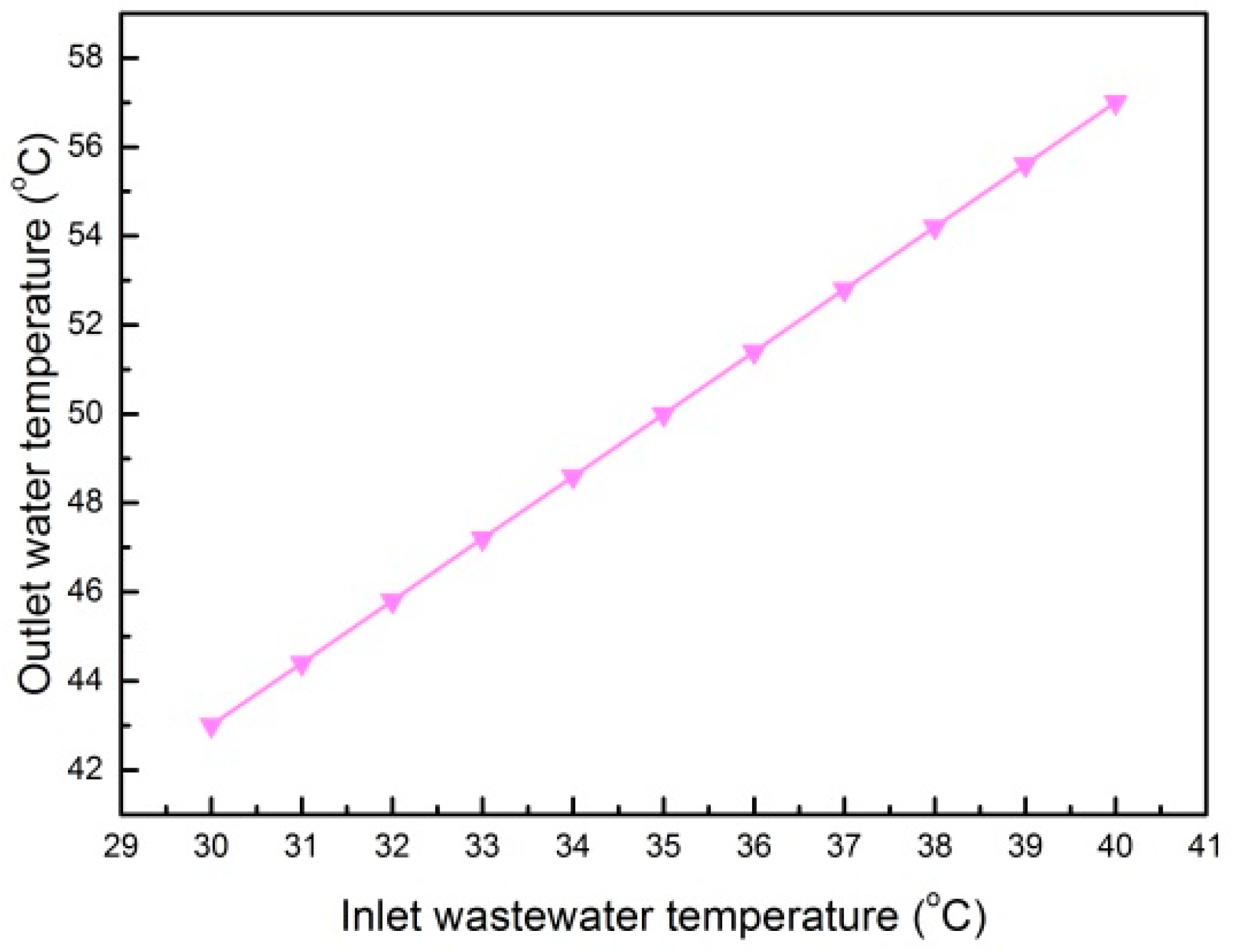
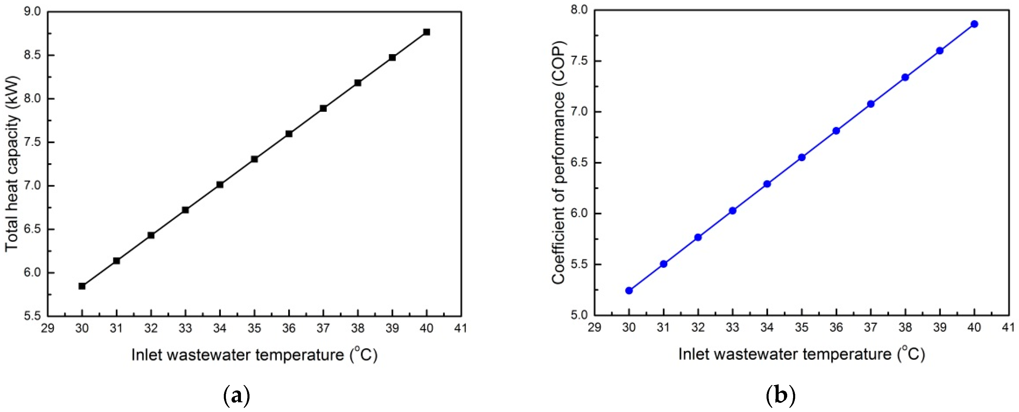
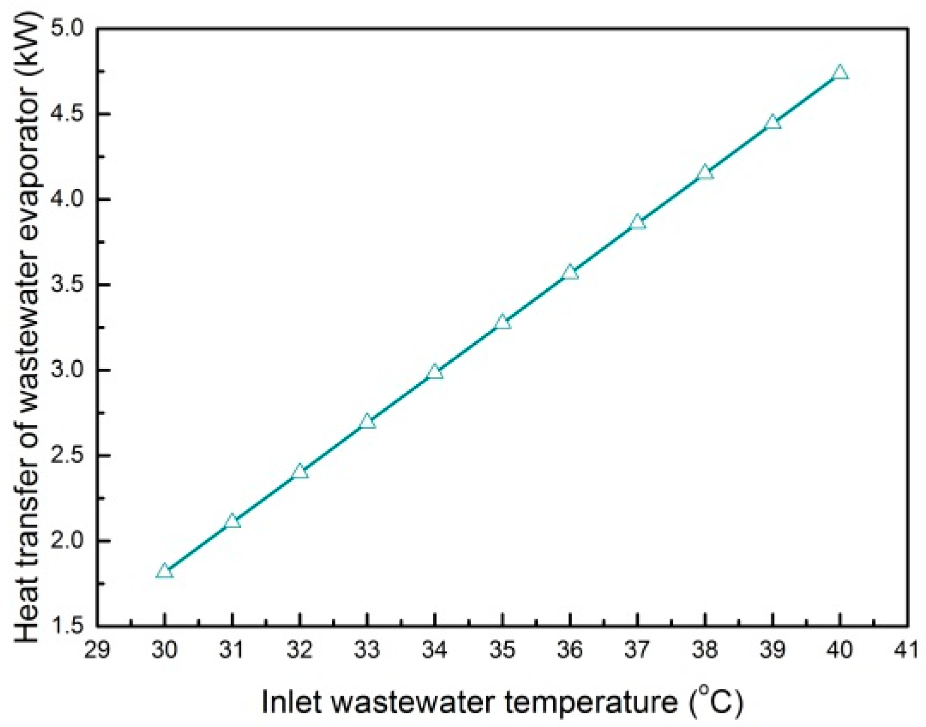
4.1. Influence of Inlet Wastewater Temperature on the System

In Case 1, the heat exchange capacity of the cooler B7 remains constant to keep the thermal consumption of the bathing process unchanged; and the mass flow of the wastewater also remains unchanged. As shown in Figure 3, the water temperature at the water mixer outlet increases as wastewater temperature at the preheater inlet increases, thus eventually, the water temperature at the condenser outlet increases since the mass flow and the temperature of the tap water are not varied.
As shown in Figure 4, the heat exchange capacity of the condenser and the total heat exchange capacity of the system increase even though the preheated water temperature and the heat exchange capacity of the preheater are kept unchanged. The power consumption of the system remains unchanged as the evaporating temperature, the condensing temperature and the mass flow of the circulating working fluid are retained. As a consequence, COP of the system increases inevitably. In the interval of the inlet wastewater temperature in Figure 4, the average COP of the system recorded is 6.552. COP reaches the maximum value of 7.862 and total heat capacity approaches to the highest value of 8.77 kW at the inlet wastewater temperature of 40 °C.
In Case 1, the heat exchange capacity of the air source evaporator is kept invariable. As shown in Figure 5, the heat exchange capacity of the wastewater source evaporator increases as the wastewater temperature at the preheater inlet and the heat exchange capacity of the condenser increase. Although the wastewater temperature at the wastewater source evaporator outlet keeps unchanged, both the wastewater temperature difference and the heat exchange capacity of the wastewater source evaporator increase. Therefore, the heat recovery of the wastewater increases correspondingly.

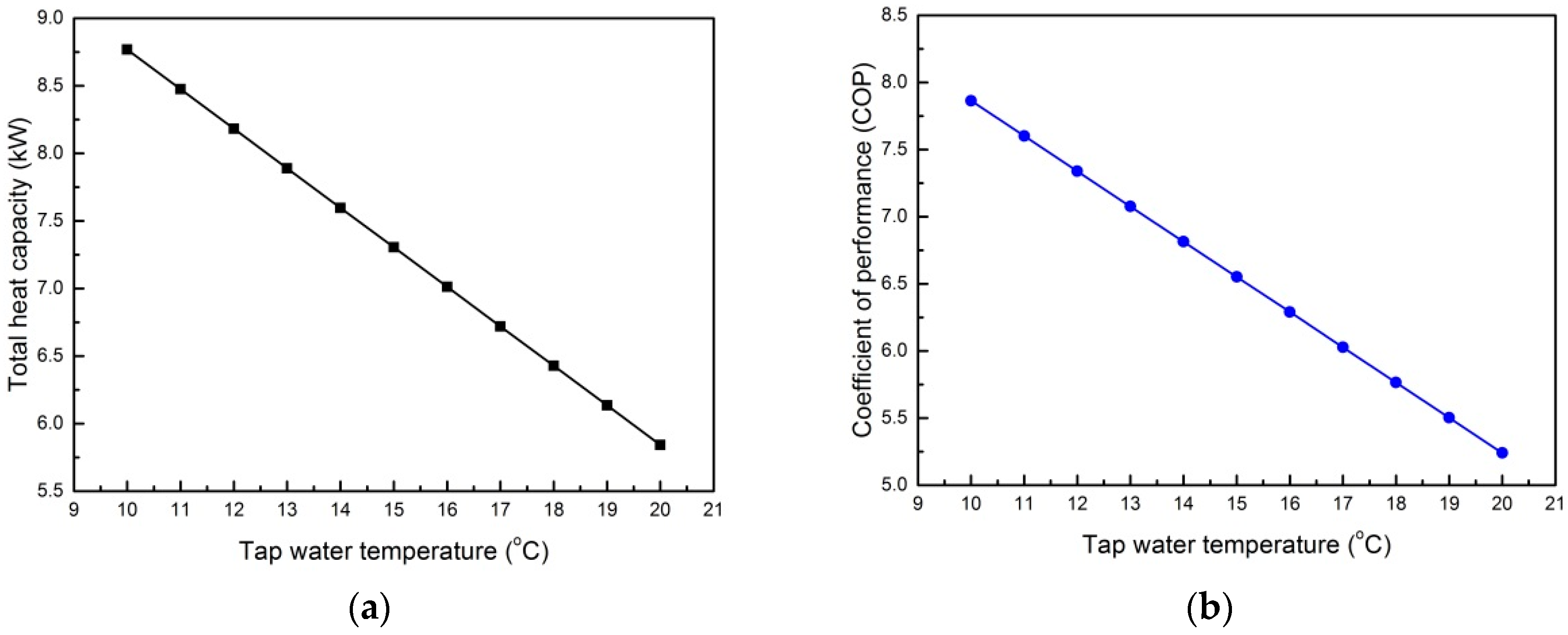
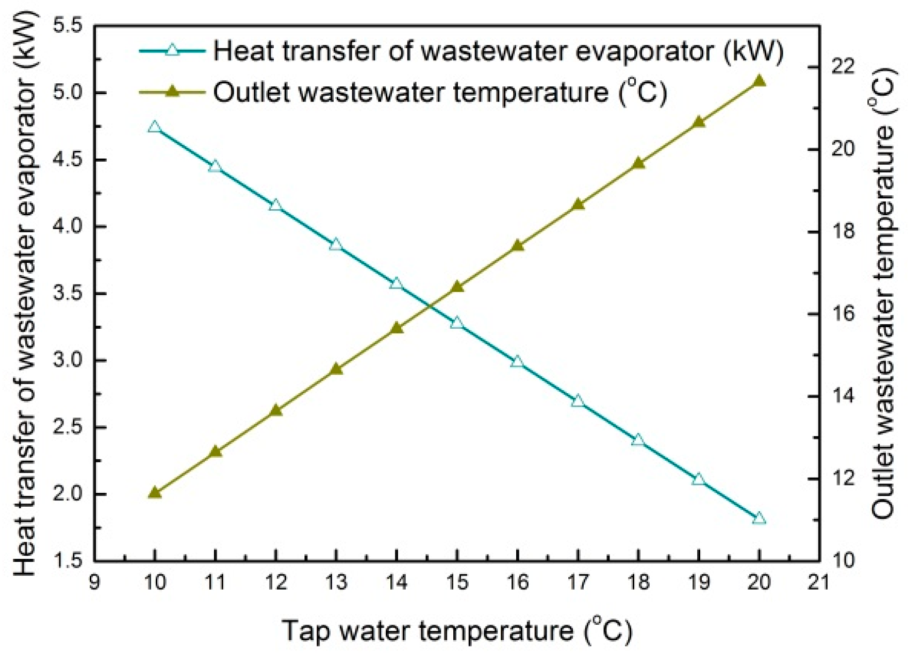
4.2. Influence of Tap Water Temperature on the System

In Case 2, the temperature of the hot water mixed by the water mixer is 40 °C; the mass flow of the tap water is unchanged. The water temperature at the condenser outlet decreases as the temperature of the tap water increases. The preheated water temperature also increases to make the heat exchange capacity of the preheater constant. As shown in Figure 6, the heat exchange capacity of the condenser and the total heat exchange capacity of the system decrease since the temperature difference of the water in the condenser decreases. The power consumption of the system is unchanged as the evaporating temperature, the condensing temperature and the mass flow of the circulating working fluid keep unchanged. Therefore, COP of the system decreases inevitably. In the interval of the tap water temperature of Figure 6, the average COP of the system is 6.552. COP reaches the maximum value of 7.864 while the total heat capacity attains the highest value of 8.76 kW at the tap water temperature of 10 °C.
In Case 2, the heat exchange capacity of the air source evaporator and the power consumption of the system remain unchanged; the mass flow and the temperature of the wastewater at the preheater inlet are unchanged; the heat exchange capacity of the preheater remains invariable; and the wastewater temperature of the preheater outlet also remains constant. As shown in Figure 7, the heat exchange capacity of the wastewater source evaporator decreases as the tap water temperature increases and the heat exchange capacity of the condenser decreases. The wastewater temperature at the wastewater source evaporator outlet increases and the heat recovery of the wastewater decreases as the heat exchange capacity of the wastewater source evaporator decreases. Outlet wastewater temperature obtains the minimum value of 11.64 °C at the tap water temperature of 10 °C.

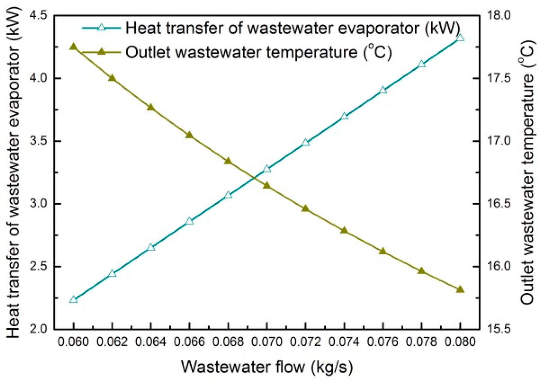
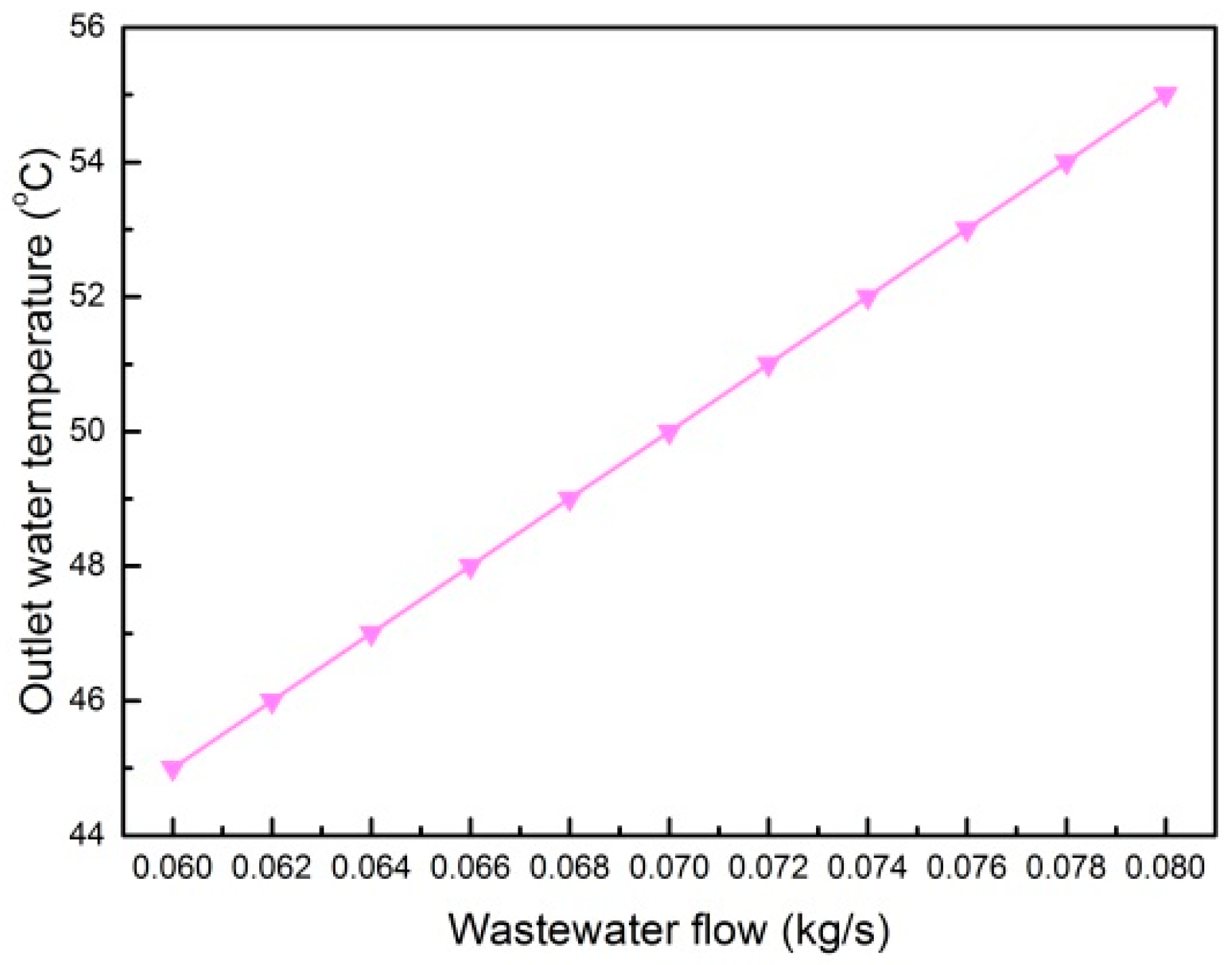
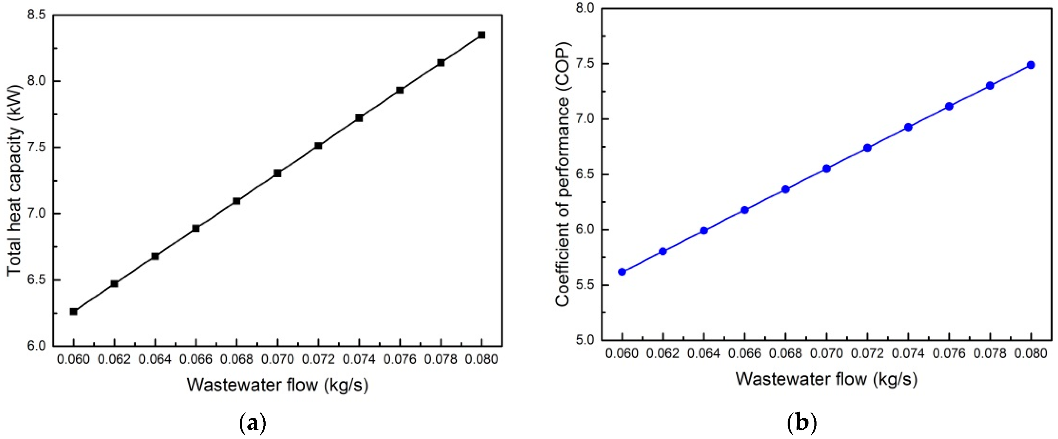
4.3. Influence of Wastewater Flow on the System

In Case 3, the temperature of the hot water mixed by the water mixer is 40 °C; the wastewater temperature in the preheater inlet remains at 35 °C while the tap water temperature remains at 15 °C. The temperature of preheated water is unchanged; and the mass flow of the tap water also remains fixed to keep the heat exchange capacity of the preheater unchanged. Wastewater flow is adjusted to simulate the influence of consumption of hot water during bathing process on the system. As shown in Figure 8, the water temperature at the condenser outlet increases to maintain the temperature of the hot water mixed by the water mixer as the wastewater flow increases.
As shown in Figure 9, the heat exchange capacity of the condenser and the total heat exchange capacity of the system both increase as the wastewater flow increases. The power consumption of the system remains unchanged as the evaporating temperature, the condensing temperature and the mass flow of the circulating working fluid keep unchanged. Therefore, COP of the system increases inevitably. In the interval of the wastewater flow in Figure 9, the average COP of the system is 6.552. COP attains the maximum value of 7.488 and total heat capacity reaches the peak value of 8.35 kW at the wastewater flow of 0.08 kg/s.
In Case 3, the heat exchange capacity of the air source evaporator and the power consumption of the system are constant. As shown in Figure 10, the heat exchange capacity of the wastewater source evaporator increases as the wastewater flow and the heat exchange capacity of the condenser increase. The wastewater temperature at the preheater inlet is 35 °C and the heat exchange capacity of the preheater stays unchanged. The wastewater temperature at the preheater outlet also increases as the wastewater flow increases. According to the simulation results, the wastewater temperature at the wastewater source evaporator outlet decreases. Thus, consequently the heat recovery of the wastewater increases.

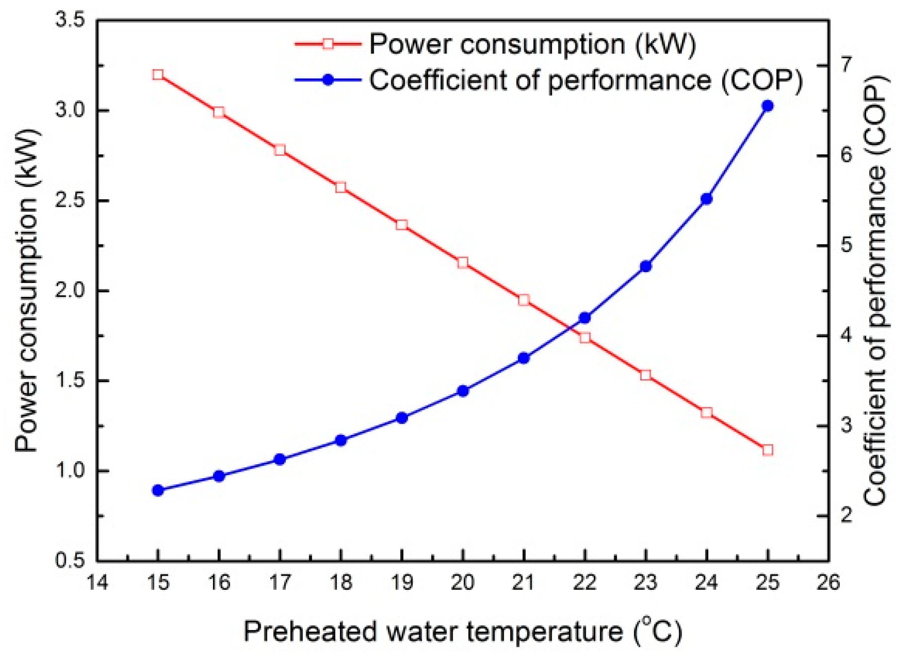
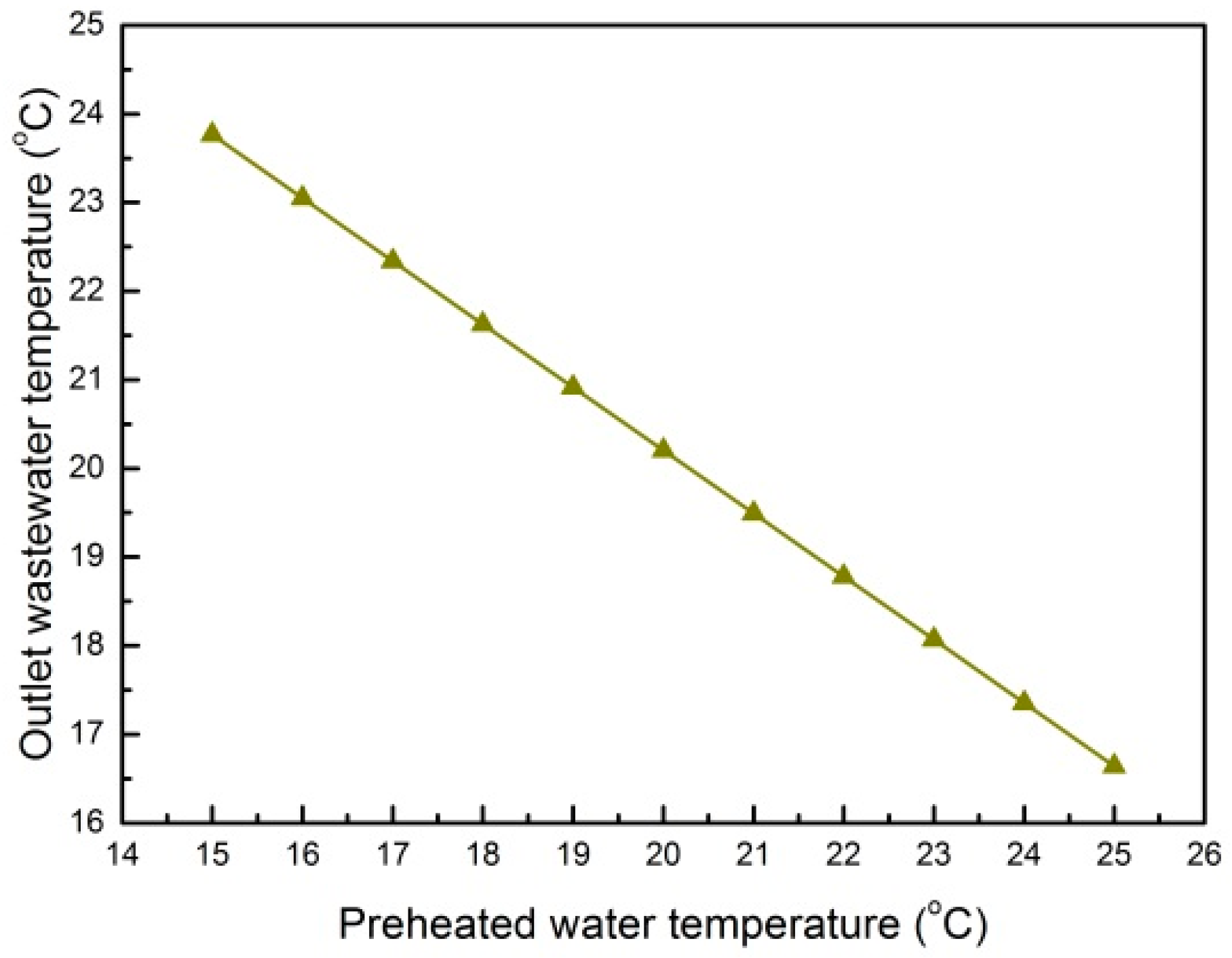
4.4. Influence of Preheated Water Temperature on the System

In Case 4, the water temperature at the condenser outlet is 50 °C; the temperature of the hot water mixed by the water mixer keeps at 40 °C; and the temperature of the tap water remains at 15 °C. The mass flows of streams 12 and 13 are fixed. The tap water is heated to 50 °C through the preheater and condenser. The total heat exchange capacity of the system remains unchanged. The heat exchange capacity of the air source evaporator keeps constant. As shown in Figure 11, the heat exchange capacity of the preheater increases and the heat exchange capacity of the condenser decreases as the preheated water temperature increases. The mass flow of the circulating working fluid is adjusted to make the heat exchange capacity of the wastewater source evaporator invariable. The mass flow of the circulating working fluid decreases as the preheated water temperature increases. Since the evaporating and condensing temperatures are fixed, the power consumption of the system decreases as the mass flow of the circulating working fluid decreases. Therefore, COP of the system increases inevitably because of the invariability of the total heat exchange capacity and the decrease of the power consumption. COP of the system reaches the peak value of 6.552, whereas the power consumption of the system approaches the least value of 1.11 kW at the preheated water temperature of 25 °C and the temperature difference of the tap water in the preheater of 10 °C.
In Case 4, the mass flow and the temperature of the wastewater at the preheater inlet remain unchanged; the heat exchange capacity of the wastewater source evaporator also remains unchanged. As shown in Figure 12, the wastewater temperature at the wastewater source evaporator outlet decreases as the heat exchange capacity of the preheater increases due to the increase of preheated water temperature. Therefore, the heat recovery of the wastewater increases.
As shown in Figure 11 and Figure 12, the system without preheater is simulated when the preheated water temperature is equal to the tap water temperature of 15 °C. Therefore, the system energy saving effect increases when the system is coupled with a preheater and the preheated water temperature or the preheater heat exchange area remains in a proper range.
From the perspective of energy consumption, adding a preheater in the system utilizes a part of energy to heat water rather than consuming power. The power consumption W decreases and COP of the system increases as Qpreheater increases.
Furthermore, addition of a preheater in the system does effective usage of the wastewater in the bathing process. The temperature of the wastewater flowing out from the system decreases and the heat recovery of the wastewater increases as the sum of Qpreheater and Qwastewater,evap is enhanced.
Based on the simulation of the system with ASPEN PLUS, the system with preheater is designed and simulated in different cases. The average COP of the system with preheater is 6.588. The system without preheater is also simulated in different cases. The average COP of the system without preheater is only 4.677. Therefore, adding a preheater in the system makes the energy saving effect enhanced.

5. Optimization and Analysis of the System Energy Savings

According to the aforementioned process simulation results, under the standard conditions of air at 25 °C, 70% relative humidity, wastewater at 35 °C, wastewater flow rate of 0.07 kg/s, tap water at 15 °C, and condenser outlet water temperature at 50 °C, ASPEN PLUS is used to optimize the system. The system COP will increase obviously as the evaporation temperature increases, the condensing temperature decreases, or the preheated water temperature increases, but the temperature cross of the evaporating temperature and the air temperature at the air source evaporator outlet or the wastewater temperature at the wastewater source evaporator outlet must be avoided while increasing the evaporating temperature. There is a limitation of the evaporating temperature. Similarly, the temperature cross of the condensing temperature and the water temperature at the condenser outlet must also be avoided when decreasing the condensing temperature. There is a limitation of the condensing temperature. When it comes to the preheater, there will be a temperature cross of the tap water and the wastewater if the preheated water temperature is increased with no limit. There is also a limitation of the preheated water temperature.
Rising the preheated water temperature can reduce the mass flow of the system circulating working fluid effectively as the evaporating temperature increases and the condensing temperature decreases. The system COP increases and the power consumption of the system decreases while keeping the total heat exchange capacity of the system constant.
According to the analysis above, with the optimization of ASPEN PLUS, increasing the evaporating and preheated water temperatures or decreasing the condensing temperature and the mass flow of the system circulating working fluid as much as possible will certainly increase the COP of the system. The theoretical COP of the system reaches the highest value of 9.784 at the evaporating temperature of 14.96 °C, the condensing temperature of 48.74 °C, the preheated water temperature of 27.19 °C. This peak COP is just a theoretical maximum and it may not be feasible in practical applications. For example, while designing and manufacturing of the system too high, a preheated water temperature may rise the system COP effectively, but it will lead to problems such as a heat exchange area that is too large and a heat exchanger without a compact structure because the water-water heat exchange of the preheater is single-phase heat exchange. Similarly, the increase of the evaporating temperature, the decrease of the condensing temperature and the mass flow of the circulating working fluid will lead to a too large structure of heat exchanger. Thus it will go against miniaturizing the total structure even though the heat exchange of the air source evaporator, the wastewater source evaporator or the condenser is two-phase heat exchange. Therefore, when designing and manufacturing a practical system, more attention has to be paid to a compact, economic and efficient system, increasing COP of system and achieving high efficiency of energy utilization.

6. Conclusions

To ensure effective usage of heat of shower wastewater and humid air in the bathroom unit, this article proposes a dual heat source heat pump bathroom unit system feasible for family use. A preheater is added to it and the COP of the system is increased. Different system cases are simulated with the process simulation software ASPEN PLUS to get optimum operating parameters for different cases. In addition, the energy saving effect of whether a preheater is installed in the system or not is compared and analyzed. The conclusions of this article can be summarized as below:
(1)
Different cases of the system are simulated. The energy saving effect and the heat recovery of the wastewater increase as inlet wastewater temperature increases, tap water temperature decreases, or wastewater flow increases;
(2)
The system with or without preheater is simulated. The system energy saving effect increases when the system is coupled with preheater and the preheated water temperature or the preheater heat exchange area are kept in a proper range;
(3)
Based on the optimization and analysis, under the standard conditions of air at 25 °C, relative humidity of 70%, wastewater at 35 °C, wastewater flow rate of 0.07 kg/s, tap water at 15 °C, and condenser outlet water temperature at 50 °C, the theoretical COP of the system can reach 9.784 at the evaporating temperature of 14.96 °C, the condensing temperature of 48.74 °C, and the preheated water temperature of 27.19 °C.
(4)
The COPs of the system of a household dual heat source heat pump water heater with and without preheater are 6.588 and 4.677, respectively. The energy saving effect of the system of household dual heat source heat pump water heater with preheater is better than that without a preheater.

Acknowledgments

This work was financially supported by the National Natural Science Foundation of China (Grant No. 51276055) and the Hebei Applied Basic Research Program of China (Grant No. 13964503D).

Author Contributions

Xiang Gou conceived the research. Yang Fu and Xiang Gou carried out the simulation. Xiang Gou, Yang Fu, Imran Ali Shah, Yamei Li, Guoyou Xu and Yue Yang participated in the analysis of the data and writing the initial manuscript. Xiang Gou, Imran Ali Shah, Enyu Wang, Liansheng Liu and Jinxiang Wu revised the manuscript and adjusted the data presentation. All authors have read and approved the manuscript.

Conflicts of Interest

The authors declare no conflict of interest.

Abbreviations

The following abbreviations are used in this manuscript:
Aheat exchange area of heat exchanger, (m2)
cspecific heat, J/(kg·K)
COPcoefficient of the system performance
Dutyduty, (W)
Fcorrection factor of Log mean temperature difference (LMTD)
henthalpy, (J/kg)
HeatFlowheat flow, (W)
Mmass flow, (kg/s)
ppressure, (Pa)
Qheat exchange capacity, (W)
Qtotaltotal heat exchange capacity of system, (W)
Qloss, Qleakheat loss of heat exchanger, (W)
Rgas constant, (J/(mol·K))
Svelocity, (m/s)
Ttemperature, (K)
△TLMLMTD of heat exchanger, (K)
Uheat exchange coefficient of heat exchanger, (W/(m2·K))
Vmideal gas molar volume, (m3/mol)
vspecific volume, (m3/mol)
Wpower consumption, (W)
Zcompressibility factor
ωacentric factor
Subscripts
ccritical
rereduced
prevprevious module
nextnext module
outoutlet
ininlet
hothot fluid
coldcold fluid
rcirculating working fluid
coolercooler
heatxheat exchanger
discompressor outlet
succompressor inlet
vvalve
air,evapair source evaporator
wastewater,evapwastewater source evaporator
condcondenser
preheaterpreheater

References

  1. Zhang, D.L.; Huang, G.Q.; Xu, Y.M.; Gong, Q.H. Waste-to-Energy in China: Key Challenges and Opportunities. Energies 2015, 8, 14182–14196. [Google Scholar] [CrossRef]
  2. Qu, J.S.; Maraseni, T.; Liu, L.N.; Zhang, Z.Q.; Yusaf, T. A Comparison of Household Carbon Emission Patterns of Urban and Rural China over the 17 Year Period (1995–2011). Energies 2015, 8, 10537–10557. [Google Scholar] [CrossRef]
  3. Nam, Y.J.; Gao, X.Y.; Yoon, S.H.; Lee, K.H. Study on the Performance of a Ground Source Heat Pump System Assisted by Solar Thermal Storage. Energies 2015, 8, 13378–13394. [Google Scholar] [CrossRef]
  4. Kim, J.S.; Nam, Y.J. A Numerical Study on System Performance of Groundwater Heat Pumps. Energies 2016, 9, 4. [Google Scholar] [CrossRef]
  5. Hepbasli, A.; Kalinci, Y. A review of heat pump water heating systems. Renew. Sustain. Energy Rev. 2009, 13, 1211–1229. [Google Scholar] [CrossRef]
  6. Ni, L.; Dong, J.K.; Yao, S.; Shen, C.; Qv, D.H.; Zhang, X.D. A review of heat pump systems for heating and cooling of buildings in China in the last decade. Renew. Energy 2016, 84, 30–45. [Google Scholar] [CrossRef]
  7. Touchie, M.F.; Pressnail, K.D. Testing and simulation of a low-temperature air-source heat pump operating in a thermal buffer zone. Energy Build. 2014, 75, 149–159. [Google Scholar] [CrossRef]
  8. Ma, G.Y.; Zhao, H.X. Experimental study of a heat pump system with flash-tank coupled with scroll compressor. Energy Build. 2008, 40, 697–701. [Google Scholar] [CrossRef]
  9. Xu, S.X.; Ma, G.Y. Research on air-source heat pump coupled with economized vapor injection scroll compressor and ejector. Int. J. Refrig. 2011, 34, 1587–1595. [Google Scholar] [CrossRef]
  10. Safa, A.A.; Fung, A.S.; Kumar, R. Performance of two-stage variable capacity air source heat pump: Field performance results and TRNSYS simulation. Energy Build. 2015, 94, 80–90. [Google Scholar] [CrossRef]
  11. Wu, J.H.; Lin, J. Thermodynamic analysis of a novel heat pump water heater with two-stage heating for a great rise of water temperature. Energy Build. 2015, 91, 97–104. [Google Scholar] [CrossRef]
  12. Bhattacharyya, S.; Garai, A.; Sarkar, J. Thermodynamic analysis and optimization of a novel N2O–CO2 cascade system for refrigeration and heating. Int. J. Refrig. 2009, 32, 1077–1084. [Google Scholar] [CrossRef]
  13. Getu, H.M.; Bansal, P.K. Thermodynamic analysis of an R744–R717 cascade refrigeration system. Int. J. Refrig. 2008, 31, 45–54. [Google Scholar] [CrossRef]
  14. Fernandez, N.; Hwang, Y.; Radermacher, R. Comparison of CO2 heat pump water heater performance with baseline cycle and two high COP cycles. Int. J. Refrig. 2010, 33, 635–644. [Google Scholar] [CrossRef]
  15. Zhang, J.F.; Qin, Y.; Wang, C.C. Review on CO2 heat pump water heater for residential use in Japan. Renew. Sustain. Energy Rev. 2015, 50, 1383–1391. [Google Scholar] [CrossRef]
  16. Wu, H.G.; Shu, P.G.; Xing, Z.W. Experimental study on performance of air source heat pumps with alternative refrigerants. Heat. Vent. Air Cond. 2006, 36, 61–62. [Google Scholar]
  17. Dong, J.K.; Li, S.; Yao, Y.; Jiang, Y.Q.; Tian, Y.; Tian, H. Defrosting performances of a multi-split air source heat pump with phase change thermal storage. Int. J. Refrig. 2015, 55, 49–59. [Google Scholar] [CrossRef]
  18. Hu, W.J.; Jiang, Y.Q.; Qv, M.L.; Ni, L.; Yao, Y.; Deng, S.M. An experimental study on the operating performance of a novel reverse-cycle hot gas defrosting method for air source heat pumps. Appl. Therm. Eng. 2011, 31, 363–369. [Google Scholar]
  19. Seong, Y.B.; Lim, J.H. Energy saving potentials of phase change materials applied to lightweight building envelopes. Energies 2013, 6, 5219–5230. [Google Scholar] [CrossRef]
  20. Lazzarin, R.M. Dual source heat pump systems: Operation and performance. Energy Build. 2012, 52, 77–85. [Google Scholar] [CrossRef]
  21. Liu, Y.; Ma, J.; Zhou, G.H.; Zhang, C.; Wan, W.L. Performance of a solar air composite heat source heat pump system. Renew. Energy 2016, 87, 1053–1058. [Google Scholar] [CrossRef]
  22. Tian, Y.; Shi, W.X.; Wang, B.L. A new ground-coupled heat pump system integrated with a multi-mode air-source heat compensator to eliminate thermal imbalance in cold regions. Energy Build. 2015, 107, 103–112. [Google Scholar]
  23. Congedo, P.M.; Lorusso, C.; Giorgi, M.G.D.; Laforgia, D. Computational fluid dynamic modeling of horizontal air-ground heat exchangers (HAGHE) for HVAC systems. Energies 2014, 7, 8465–8482. [Google Scholar] [CrossRef]
  24. Hepbasli, A.; Biyik, E.; Ekren, O.; Gunerhan, H.; Araz, M. A key review of wastewater source heat pump (WWSHP) systems. Energy Convers. Manag. 2014, 88, 700–722. [Google Scholar] [CrossRef]
  25. Tanha, K.; Fung, A.S.; Kuma, R. Performance of two domestic solar water heaters with drain water heat recovery units: Simulation and experimental investigation. Appl. Therm. Eng. 2015, 90, 444–459. [Google Scholar] [CrossRef]
  26. Liu, L.B.; Fu, L.; Jiang, Y. Application of an exhaust heat recovery system for domestic hot water. Energy 2010, 35, 1476–1481. [Google Scholar] [CrossRef]
  27. Kahraman, A.; Çelebi, A. Investigation of the Performance of a Heat Pump Using Waste Water as a Heat Source. Energies 2009, 2, 697–713. [Google Scholar] [CrossRef]
  28. Wong, L.T.; Mui, K.W.; Guan, Y. Shower water heat recovery in high-rise residential buildings of Hong Kong. Appl. Energy 2010, 87, 703–709. [Google Scholar] [CrossRef]
  29. Liu, L.B.; Fu, L.; Zhang, S.G. The design and analysis of two exhaust heat recovery systems for public shower facilities. Appl. Energy 2014, 132, 267–275. [Google Scholar] [CrossRef]
  30. Chen, W.; Liang, S.Q.; Guo, Y.X.; Cheng, K.Y.; Gui, X.H.; Tang, D.W. Investigation on the thermal performance and optimization of a heat pump water heater assisted wish shower waste water. Energy Build. 2013, 64, 172–181. [Google Scholar] [CrossRef]
  31. Dong, J.K.; Zhang, Z.; Yao, Y.; Jiang, Y.Q.; Lei, B. Experimental performance evaluation of a novel heat pump water heater assisted with shower drain water. Appl. Energy 2015, 154, 842–850. [Google Scholar] [CrossRef]
  32. Chen, Z.S.; Tao, W.Q.; Zhu, Y.W.; Hu, P. Performance analysis of air-water dual source heat pump water heater with heat recovery. Sci. China Technol. Sci. 2012, 55, 2148–2156. [Google Scholar] [CrossRef]
  33. Zhang, C.; Dong, J.Y.; Zhao, X.D.; Zhou, G.H. The influence factors of the compound heat-exchanging temperature difference of dual-source compound heat-exchanger. Cryog. Supercond. 2012, 40, 68–72. [Google Scholar]
  34. Zhang, C.; Dong, J.Y.; Zhao, X.D.; Zhou, G.H. Structure parameter optimization of air-water dual-source compound heat-exchanger. Fluid Mach. 2012, 40, 61–64. [Google Scholar]
  35. Mansouri, R.; Boukholda, I.; Bourouis, M.; Bellagi, A. Modelling and testing the performance of a commercial ammonia/water absorption chiller using Aspen-Plus platform. Energy 2015, 93, 2374–2383. [Google Scholar] [CrossRef]
  36. De Guido, G.; Langè, S.; Pellegrini, L.A. Refrigeration cycles in low-temperature distillation processes for the purification of natural gas. J. Nat. Gas Sci. Eng. 2015, 27, 887–900. [Google Scholar] [CrossRef] [Green Version]
  37. Somers, C.; Mortazavi, A.; Hwang, Y.; Radermacher, R.; Rodgers, P.; Al-Hashimi, S. Modeling water/lithium bromide absorption chillers in ASPEN Plus. Appl. Energy 2011, 88, 4197–4205. [Google Scholar] [CrossRef]
  38. Peng, D.Y.; Robinson, D.B. A New Two-Constant Equation of State. Ind. Eng. Chem. Fundam. 1976, 15, 59–64. [Google Scholar] [CrossRef]
  39. Soave, G. Equilibrium constants from a modified Redlich-Kwong equation of state. Chem. Eng. Sci. 1972, 27, 1197–1203. [Google Scholar] [CrossRef]
  40. Spencer, R.C.; Meyer, C.A. The 1967 ASME Steam tables. Nav. Eng. J. 1968, 80, 751–758. [Google Scholar]
Figure 1. Schematic diagram of the bathroom unit: 1—Wastewater outlet; 2—Tap water inlet; 3—Compressor; 4—Condenser; 5—Water tank; 6—Air source evaporator; 7—Expansion valve; 8—Water mixer and control system; 9—Preheater; 10—Wastewater source evaporator.
Energies 09 01026 g001
Figure 2. Flow chart of the steady simulation with ASPEN PLUS.
Energies 09 01026 g002
Figure 3. Influence of inlet wastewater temperature on outlet water temperature.
Energies 09 01026 g003
Figure 4. Influence of inlet wastewater temperature on total heat capacity and coefficient of performance (COP): (a) Total heat capacity; (b) COP.
Energies 09 01026 g004
Figure 5. Influence of inlet wastewater temperature on heat transfer of wastewater evaporator.
Energies 09 01026 g005
Figure 6. Influence of tap water temperature on total heat capacity and COP: (a) Total heat capacity; (b) COP.
Energies 09 01026 g006
Figure 7. Influence of tap water temperature on heat transfer of wastewater evaporator and outlet wastewater temperature.
Energies 09 01026 g007
Figure 8. Influence of wastewater flow rate on outlet water temperature.
Energies 09 01026 g008
Figure 9. Influence of wastewater flow rate on total heat capacity and COP: (a) Total heat capacity; (b) COP.
Energies 09 01026 g009
Figure 10. Influence of wastewater flow rate on heat transfer of wastewater evaporator and outlet wastewater temperature.
Energies 09 01026 g010
Figure 11. Influence of preheated water temperature on power consumption and COP.
Energies 09 01026 g011
Figure 12. Influence of preheated water temperature on outlet wastewater temperature.
Energies 09 01026 g012
Table 1. Different working conditions of the steady simulation.
CaseWastewater Temperature (°C)Tap Water Temperature (°C)Wastewater Mass Flow (kg/s)Preheated Water Temperature (°C)
130–40150.0725
23510–200.0720–30
335150.06–0.0825
435150.0715–25

