Article

Comparative Study of Shell and Helically-Coiled Tube Heat Exchangers with Various Dimple Arrangements in Condensers for Odor Control in a Pyrolysis System

Division of Environmental and Plant Engineering, Korea Institute of Civil Engineering and Building Technology, 283, Goyang-daero, Ilsanseo-gu, Goyang-si, Gyeonggi-do 10223, Korea
*
Author to whom correspondence should be addressed.
Energies 2016, 9(12), 1027; https://doi.org/10.3390/en9121027
Submission received: 4 October 2016 / Revised: 18 November 2016 / Accepted: 30 November 2016 / Published: 5 December 2016
(This article belongs to the Special Issue Engineering Fluid Dynamics)

Abstract

:
This study performed evaluations of the shell and helically-coiled tube heat exchangers with various dimple arrangements, that is, flat, inline, staggered, and bulged, at different Dean numbers (De) and inlet temperatures of a hot channel. Conjugated heat transfer was analyzed to evaluate the heat transfer performance of the exchangers through temperature difference between the inlet and outlet, Nusselt number inside the coiled tube, and pressure drop of the coiled tube by using 3-D Reynolds-averaged Navier–Stokes (RANS) equations with shear stress transport turbulence closure. A grid dependency test was performed to determine the optimal number of the grid system. The numerical results were validated using the experimental data, and showed good agreement. The inline and staggered arrangements show the highest temperature differences through all De. The staggered arrangement shows the best heat transfer performance, whereas the inline arrangement shows the second highest performance with all ranges of De and the hot channel’s inlet temperature. The inline and staggered arrangements show the highest pressure drop among all inlet temperatures of the hot channel.

1. Introduction

Pyrolysis is defined as one of the most effective and efficient processes of thermal decomposition to obtain energy in the form of char from resources in an anoxic condition. This process has the ability to convert sewage sludge, biomass, and other carbonaceous materials to reusable fuels [1]. Biomass pyrolysis results in three products: biochar, bio-oil, and gas [2]. Biochar is a solid carbon-rich byproduct obtained through the thermal stabilization of biomass or any other organic matter [3]. Bio-oil has a good feedstock for power generation as it contains high amounts of energy, which is, in some cases, comparable to that of the fossil fuels after upgrading [4]. Moreover, gas produced through pyrolysis has high energy, which is, in some cases, comparable to that of the coal used in industries as feedstocks for fuel [5,6]. Food wastes are known as good resources of pyrolysis among various raw materials.
Food wastes have a high energy content. Consequently, they offer a good potential as feedstocks for pyrolysis in power plants [7]. Therefore, many researchers and industry officials have focused on food-waste pyrolysis as a future source of energy supply. However, in the pyrolysis of food wastes, numerous types of odors are generated and the dust formed in the process, including the dry process, can be a factor of ignition [8,9]. One of the best and commonly used methods to solve this problem is condensation [10]. By condensing, the byproducts (such as the odors or dust) of the pyrolysis process are reduced and removed. The shell and tube heat exchanger (STHX) systems have played an important role to realize condensation [11], and it is important to increase the heat transfer performance for the best condensation conditions.
Therefore, many researchers focus on the STHX systems, especially on the heat transfer performance. Selbaş et al. [12] estimated the minimum heat transfer area required for a given heat duty, as it governs the overall cost of the heat exchanger, by using the genetic algorithms (GA) with varying design variables, such as the outer tube diameter, tube layout, number of tube passes, outer shell diameter, baffle spacing, and baffle cut. In addition, they concluded that the combinatorial algorithms, such as GAs, provide significant improvement in the optimal designs than the conventional designs. Babu and Munawar [13] applied differential evolution (DE) and its various strategies for the optimal design of STHXs. They determined that the DE, an exceptionally simple evolution strategy, is significantly faster than the GA and yields the global optimum for several key parameters. Xie et al. [14] experimentally investigated three heat exchangers by applying an artificial neural network (ANN) to the heat transfer analysis of STHXs with segmental or continuous helical baffles, and predicted outlet temperature differences on each side and overall heat transfer rates. As a result, the maximum deviation between the predicted results and experimental data was less than 2%, and the ANN showed superiority for prediction than correlation. Fesanghary et al. [15] explored the use of global sensitivity analysis (GSA) and a harmony search algorithm (HSA) for design optimization of STHXs from the economic viewpoint; total cost of STHXs are identified using GSA. They compared the HSA results with those obtained using GA, and revealed that the HSA can converge to an optimum solution with higher accuracy. Guo et al. [16] applied the field synergy principle to the optimization design of an STHX with segmental baffles by using the GA to solve the heat exchanger optimization problems by using multiple design variables. The comparison with the conventional heat exchanger optimization design approach, with the total cost as the objective function, shows that the field synergy number maximization approach is more advantageous. Zhang et al. [17] experimentally compared several STHXs: one with segmental baffles and four with helical baffles at helix angles of 20°, 30°, 40°, and 50°. The results show that, based on the same shell-side flow rate, the heat transfer coefficient of the heat exchanger with helical baffles is lower than that of the heat exchanger with segmental baffles, while the shell-side pressure drop of the exchanger with helical baffles is even lower.
As mentioned above, many researchers have focused on the STHX systems to enhance the heat transfer performance during condensation of odorized materials. However, there has been no attempt to develop a new combined system with the dimpled helical tube that enhances the heat transfer performance of the STHX systems. The tube was devised to intentionally enhance the heat transfer performance. Thus, the superiority of the dimpled helical tube was evaluated. However, the various arrangements of the dimples, such as staggered, in-lined, and alternating arrangements, must be assessed. Therefore, the present study suggests several arrangements of the dimples on the helical tube; the heat transfer performance was evaluated in terms of the Nusselt number. In addition, the effect of the Dean number (De) on the heat transfer performance was estimated. Furthermore, the performance of the proposed STHX systems was comparatively assessed using 3-D Reynolds-averaged Navier–Stokes (RANS) equations.

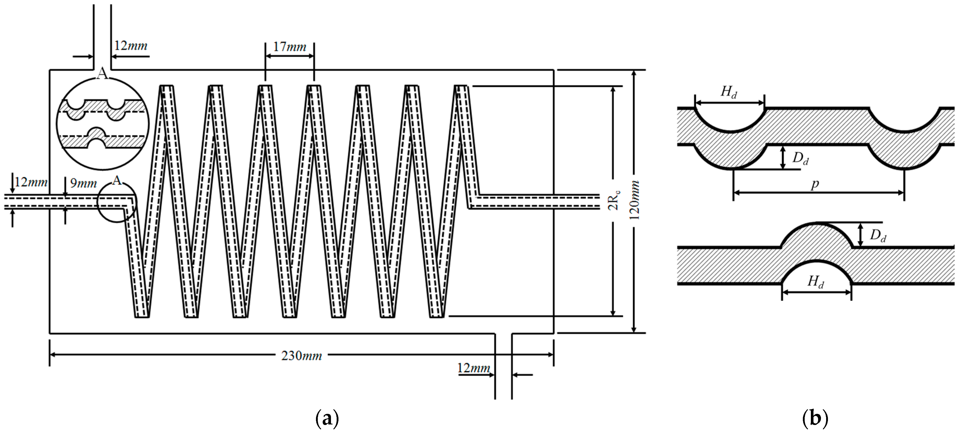
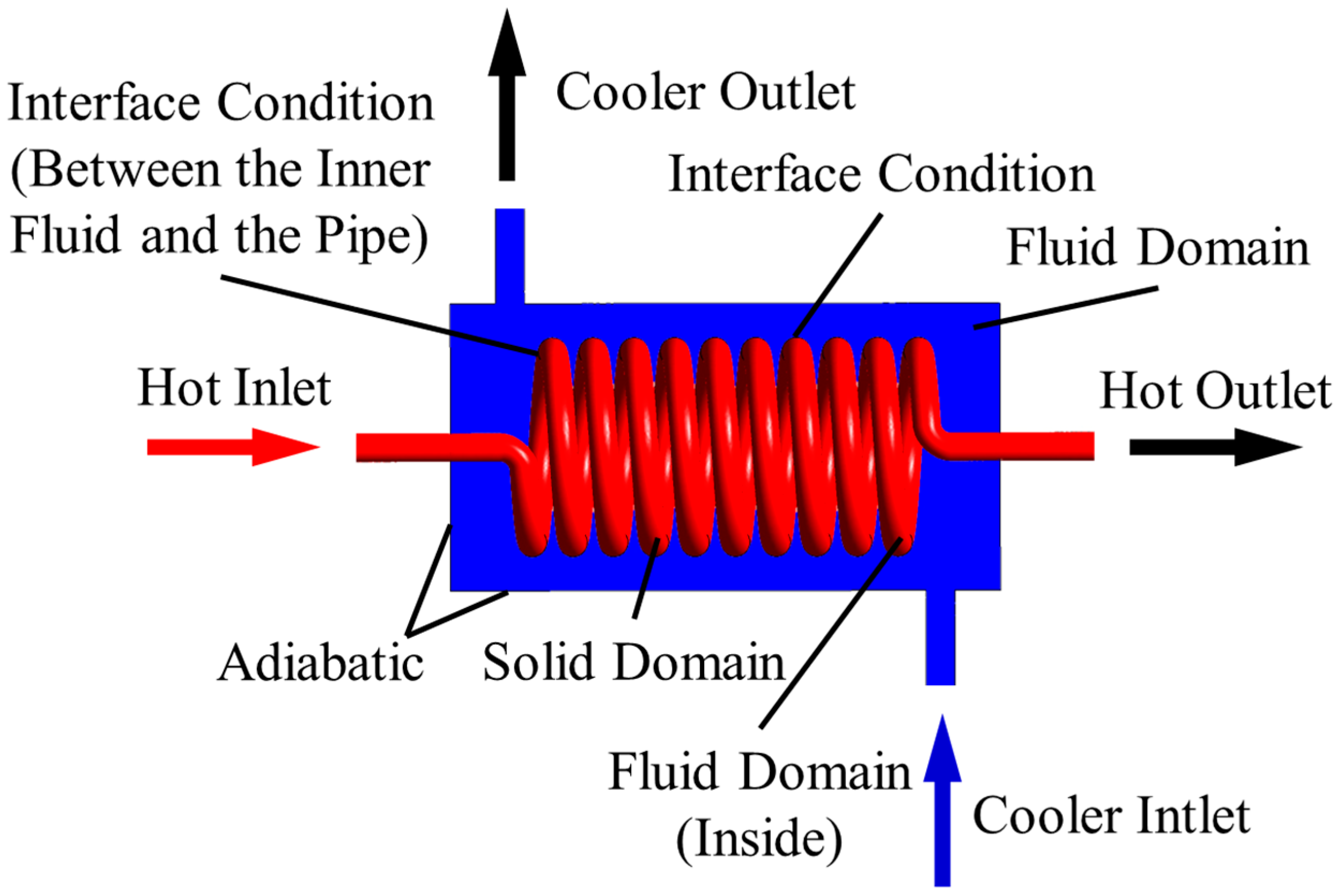
2. Configurations of the Shell and Helically-Coiled Tube Heat Exchanger Systems

Figure 1 presents dimensions of the shell and helically-coiled dimpled-tube heat exchanger system. The overall system has a length of 230 mm and diameter of 120 mm. The coolant enters through the inlet of 12 mm diameter, and exits through the same diameter outlet. The outer and inner diameters of the helical tube are 12 and 9 mm, respectively. The helical tube has 10 turns with the coil pitch of 17 mm and a curvature radius of 2Rc, as shown in Figure 1a. The height (Hd) and diameter (Dd) of the dimple are 1.336 and 6.903 mm, respectively; the pitch of the dimple (p) is 5.628 mm, as shown in Figure 1b. Figure 2 shows the schematic of the dimple arrangement. The dimples on the helical tube are arranged in the following three arrangements: staggered, inline, and bulged. Further, this tube’s heat transfer performance was compared with that of the flat helical tube. The heat transfer enhancement structure consists of two dimples: concave and convex dimples. However, the bulged arrangement consists of convex dimples.

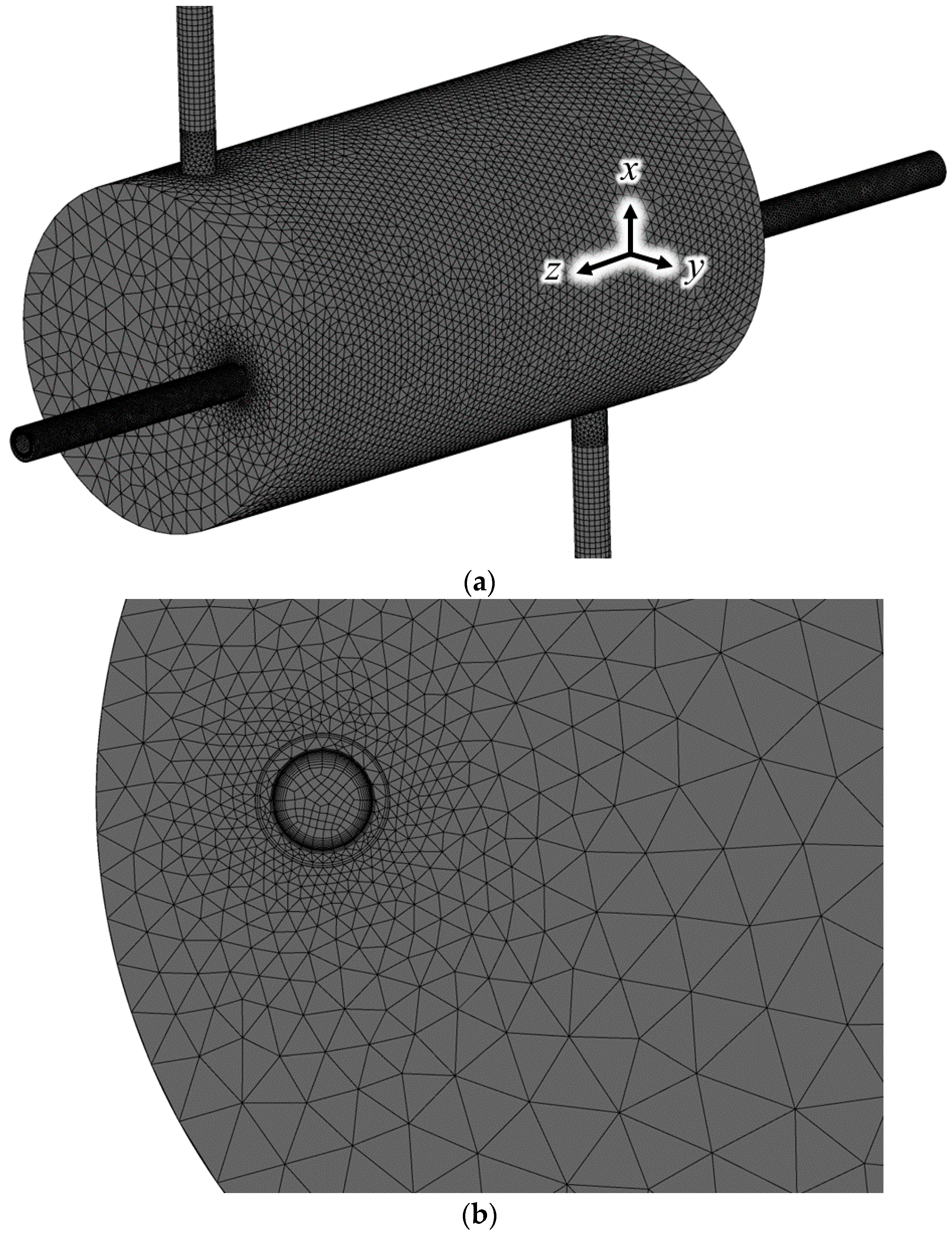
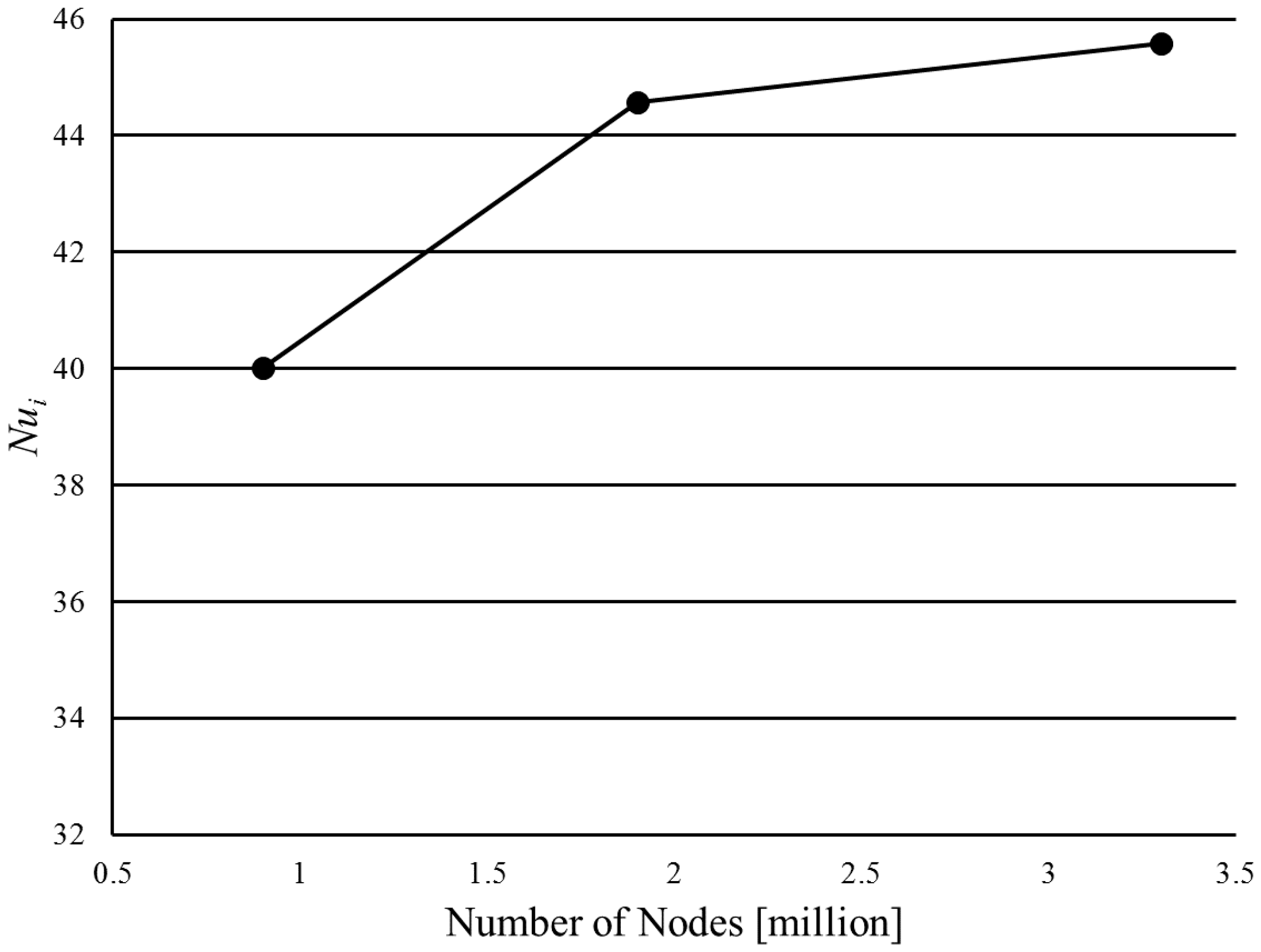
3. Numerical Analysis

The present numerical analysis was performed using commercial computational fluid dynamics code ANSYS CFX 17.0 (© 2016 ANSYS, Inc., Canonsburg, PA, USA) [18] to solve the governing equations for 3-D steady turbulent flow and conjugate heat transfer in the heat exchanger system. For a steady, incompressible, turbulent flow, the continuity and Reynolds-averaged Navier-Stokes equations are given as:
x i ( ρ u i ) = 0
x j ( ρ u i u j ) = p x i + x j [ μ ( u i x j + u j x i 2 3 u k x k δ i j ) ρ u i u j ¯ ] + S ¯ i u
where u i and u i are mean and fluctuating velocities, respectively, and S ¯ i u is a production term. The shear stress transport (SST) model [19] with automatic wall treatment is used as a turbulence closure model. In addition, a second-order-accurate numerical scheme was used to discretize the governing equations. Moreover, a high-resolution scheme that uses a special nonlinear procedure at each node was used to discretize the advection terms.
Figure 3 shows the computational domain and boundary conditions. Water and Behran Hararat oil were respectively used as working fluids for the shell-side fluid and tube-side coolant. The thermophysical properties of the oil [20] were varied to state the dependency of the working fluid on temperature with an accuracy of 1.0%. The importance of temperature-dependent properties was already emphasized by many researchers [21,22]. The properties were defined as follows:
μ = 1.31 × 10 7 T 3 + 3.2813 × 10 5 T 2 2.916875 × 10 3 T + 9.9418750 × 10 2 C p = 3.7093 T + 1814.3575 k = 8.7 × 10 5 T + 0.164570 ρ = 0.725 T + 877.350
where T ( ) is the caloric mean temperature of oil through the coiled heat. At the shell-side inlet, a mass flow rate of 0.06 kg/s was applied with a temperature of 287.15 K; at the tube-side inlet, a mass flow rate of 0.008–0.054 kg/s was assigned to maintain the De in the range of 17–195 with a temperature of 45 °C, 55 °C, and 75 °C. The De is defined as follows:
D e = R e i ( d 2 R c ) 1 / 2
where Rei is the Reynolds number at the inside of the coiled tube, d is the diameter of the coiled tube, and Rc is the curvature radius. A relative pressure of 0 Pa was applied at both the shell- and tube-side outlets. At the contact surface between the solid and fluid domains, an interface condition was applied to estimate the conjugate heat transfer by using a general grid interface connection [18], which has been applied to many numerical analyses of different physical domains, such as rotating and stationary domains [23], or fluid and solid domains [24]. All of the wall surfaces on the outside of the heat exchanger and calculation domain were assumed to be nonslip and adiabatic.
Figure 4 shows an example of the computational grid system, which comprises a tetrahedral mesh in most parts, and a hexahedral mesh near the inlet and outlet, to obtain more accurate inlet and outlet flow velocity profiles and reduce the overall number of grids. The mesh was finer in the helically-coiled tube and its surroundings for a complex flow phenomenon. A growth factor of 1.2 was adopted from the concentrated region to have a proper expansion factor for calculation stability.
As the convergence criteria, the root-mean-square relative residual values of all the fluid and solid parameters were set to 1.0 × 10⁻⁵. The computational time per analysis was about 12 h, and the time was dependent on the complexity of the geometry and the number of the grid system.

4. Result and Discussion

To determine the optimal number of the grid elements, three nodes of the grid system in the range of 900,000 to 3,300,000 were tested; Figure 5 illustrates the test result for a flat helical tube at De = 111. The Nusselt number on the inner surface of the coiled tube (Nui) was used as a criterion for the comparison and is defined as Nui = hidi/k, where hi and k are the area-averaged convective heat transfer coefficient at the surface of the inner fluid domain and the thermal conductivity of the inner fluid, as shown in Equation (3), respectively. The deviation of the coarsest grid system (0.9 million) shows a relative error of 12.22% compared with the finest grid system (3.3 million), while the deviation of the second finest grid system (1.9 million) shows a relative error of 2.19%. Resultantly, approximately 1.9 million nodes was decided to be the optimum number of nodes for calculation; however, the number of nodes varied with the shape of the coiled tube from 1.9 to 2.1 million.
To assess the validity of the numerical solutions, the results were compared with the experimental data of the flat coiled tube, as shown in Figure 6. The validation was performed for Nui with various De and two temperatures at the inlet of the tube-side. The results of Ti = 55 °C showed a deviation of 14.0% relative error at De = 31.8, and 1.7% averaged relative error at De > 66.7. The results of Ti = 70 °C showed 5.7% averaged relative error at De > 140, and 11.5% averaged relative error at De < 98.3. Overall, the present numerical results show good agreement with the experimental data.
Figure 7 presents the temperature difference charts of the hot channel with various De. The difference was calculated as ΔT = Thot,inThot,out. The deviation in each case shows an almost similar trend. The inline and staggered arrangements show the highest temperature differences through all De values, whereas the staggered arrangement shows a slightly higher temperature difference. In addition, the bulged arrangement shows a higher temperature difference at lower De (<40) with Thot,in = 45 and 55 °C; however, as De increases, results similar with those of the flat case are observed. At Thot,in = 70 °C with a higher De (>100), the flat case shows a slightly higher temperature difference. It was obvious that increase in the residence time of the hot channel fluid increased the temperature difference of the hot channel.
Figure 8 shows temperature contours inside the helically-coiled tube with the velocity vector of the cold channel on the y–z plane at x = 0; De = 17.87 and inlet temperature of the hot channel is 45 °C. The results were focused on the temperature variation inside the coiled tube with a circumferential fluid flow on the shell-side. The hot fluid was affected by the centric fluid flow rather than outer fluid flow on the shell-side; therefore, the thermal layer inside the tube started at the inner surface for all cases. The high temperature fluid flows along the shape of the helically-coiled tube and the fluid that is closer to the center of the shell flows more slowly than the fluid that is farther from the center of the shell due to the centrifugal effect. Moreover, the fluid inside the shell-side flows faster at the inner area than at the outer (near wall) area. As the inline and staggered arrangements show rapid temperature variation in the coiled tube, the thermal layer was observed simultaneously from the inner and outer surfaces, and a lower temperature of the hot channel was observed near the exit, as shown in Figure 7.
Figure 9 presents the Nusselt number inside the helically-coiled tube with various De values and inlet temperatures of the hot channel. The staggered arrangement shows the best heat transfer performance, while the inline arrangement shows the second best performance for all ranges of De and inlet temperature. The bulged arrangement shows a higher than the flat arrangement at a lower De (<30); however, the flat arrangement shows a higher Nui value at a higher De (>40) at Thot,in = 45 °C. A similar result can be observed for Thot,in = 55 °C. The deviation between each case was increased with a higher De value at all inlet temperatures.
Figure 10 shows pressure drops at the helically-coiled tube with various De. The inline and staggered arrangements with the best heat transfer performance show the highest pressure drop for all inlet temperatures of the hot channel, and the flat arrangement shows the lowest pressure drop for all inlet temperatures. The deviations between each case increased with the De for all inlet temperatures.
Overall, introducing the staggered arrangement structure to the shell and helically-coiled tube system efficiently enhanced the heat transfer performance; however, the pressure drop increased through the system.
It is generally known that the performance of the dimple, as a device of heat transfer augment, can be influenced by the shape of the dimple, such as the dimple height, dimple width, and dimple periodic arrangement. In a further study, the effect of geometric variables of the dimple will be investigated to optimize the system and to generalize the results to other dimple systems.

5. Conclusions

This paper described the evaluations of the shell and helically-coiled tube heat exchangers with various dimple arrangements, flat, inline, staggered, and bulged, at different De and inlet temperatures of the hot channel. These evaluations were performed for determining the temperature difference between the inlet and outlet, Nusselt number inside the coiled tube, and pressure drop of the coiled tube by using 3-D RANS equations with SST turbulence closure. A grid dependency test was performed to determine the optimal number of the grid system; approximately 190 million nodes were found to be optimal for calculation. The numerical results were validated using the experimental data, and showed good agreement within the average relative error of 1.7%–5.7%. The inline and staggered arrangements show the highest temperature differences for all values of De, and the bulged and flat arrangements show lower temperature differences. The staggered arrangement shows the best heat transfer performance, followed by the inline arrangement for all ranges of De and inlet temperature of the hot channel. The inline and staggered arrangements show the highest pressure drop and the flat arrangement shows the lowest pressure drop through all inlet temperatures of the hot channel. The performance is expected to be enhanced further by optimizing the geometric configuration through a range of optimization techniques [25,26,27,28].

Acknowledgments

This research was supported by a grant (16AUDP-B083704-03) from Architecture & Urban Development Research Program funded by Ministry of Land, Infrastructure and Transport of Korean government.

Author Contributions

Jun-Ho Jo and Ye-Eun Lee supported the numerical investigation, and the revision of the manuscript. Yeong-Seok Yoo supervised the project, and provided professional technical guidelines and insights. Sun-Min Kim designed the project, analyzed the data, wrote the draft of the paper, and carried out the final revision of the paper.

Conflicts of Interest

The authors declare no conflict of interest.

Nomenclature

Cpspecific heat (J/kg·K)
ddiameter (m)
DeDean number
hconvective heat transfer coefficient (W/m2·K)
Hheight (m)
NuNusselt number
ppitch (m)
Rccurvature radius (m)
ReReynolds number
Ttemperature (K)
x, y, zCartesian coordinates (m)

Greek symbols

μdynamic viscosity (Pa·s)
kthermal conductivity
ρdensity (kg/m3)
νkinematic viscosity (m2/s)
τshear stress (N/m2)

Subscripts

ddimple
hothot channel
coldcold channel
ininner
outouter

References

  1. Doshi, V.A.; Vuthaluru, H.B.; Bastow, T. Investigations into the control of odour and viscosity of biomass oil derived from pyrolysis of sewage sludge. Fuel Process. Technol. 2005, 86, 885–897. [Google Scholar] [CrossRef]
  2. Tripathi, M.; Sahu, J.N.; Ganesan, P. Effect of process parameters on production of biochar from biomass waste through pyrolysis: A review. Renew. Sustain. Energy Rev. 2016, 55, 467–481. [Google Scholar] [CrossRef]
  3. Mohanty, P.; Pant, K.K.; Naik, S.N.; Parikh, J.; Hornung, A.; Sahu, J.N. Synthesis of green fuels from biogenic waste through thermochemical route–The role of heterogeneous catalyst: A review. Renew. Sustain. Energy Rev. 2014, 38, 131–153. [Google Scholar] [CrossRef]
  4. Mašek, O.; Budarin, V.; Gronnow, M.; Crombie, K.; Brownsort, P.; Fitzpatrick, E.; Hurst, P. Microwave and slow pyrolysis biochar: Comparison of physical and functional properties. J. Anal. Appl. Pyrolysis 2013, 100, 41–48. [Google Scholar] [CrossRef]
  5. Park, H.J.; Dong, J.I.; Jeon, J.K.; Park, Y.K.; Yoo, K.S.; Kim, S.S.; Kim, J.; Kim, S. Effects of the operating parameters on the production of bio-oil in the fast pyrolysis of Japanese larch. Chem. Eng. J. 2008, 143, 124–132. [Google Scholar] [CrossRef]
  6. Fu, P.; Hu, S.; Xiang, J.; Sun, L.; Su, S.; Wang, J. Evaluation of the porous structure development of chars from pyrolysis of rice straw: Effects of pyrolysis temperature and heating rate. J. Anal. Appl. Pyrolysis 2012, 98, 177–183. [Google Scholar] [CrossRef]
  7. Ahmed, I.I.; Gupta, A.K. Pyrolysis and gasification of food waste: Syngas characteristics and char gasification kinetics. Appl. Energy 2010, 87, 101–108. [Google Scholar] [CrossRef]
  8. Digman, B.; Kim, D.S. Review alternative energy from food processing wastes. Environ. Prog. 2008, 27, 524–537. [Google Scholar] [CrossRef]
  9. Rappert, S.; Müller, R. Odor compounds in waste gas emissions from agricultural operations and food industries. Waste Manag. 2005, 25, 887–907. [Google Scholar] [CrossRef] [PubMed]
  10. Burgess, J.E.; Parsons, S.A.; Stuetz, R.M. Developments in odour control and waste gas treatment biotechnology—A review. Biotechnol. Adv. 2001, 19, 35–63. [Google Scholar] [CrossRef]
  11. Wang, Q.; Chen, G.; Chen, Q.; Zeng, M. Review of improvements on shell-and-tube heat exchangers with helical baffles. Heat Transf. Eng. 2010, 31, 836–853. [Google Scholar] [CrossRef]
  12. Selbas, R.; Kızılkan, Ö.; Reppich, M. A new design approach for shell-and-tube heat exchangers using genetic algorithms from economic point of view. Chem. Eng. Process. 2006, 45, 268–275. [Google Scholar] [CrossRef]
  13. Babu, B.V.; Munawar, S.A. Differential evolution strategies for optimal design of shell-and-tube heat exchangers. Chem. Eng. Sci. 2007, 62, 3720–3739. [Google Scholar] [CrossRef]
  14. Xie, G.N.; Wang, Q.W.; Zeng, M.; Luo, L.Q. Heat transfer analysis for shell-and-tube heat exchangers with experimental data by artificial neural networks approach. Appl. Therm. Eng. 2007, 27, 1096–1104. [Google Scholar] [CrossRef]
  15. Fesanghary, M.; Damangir, E.; Soleimani, I. Design optimization of shell and tube heat exchangers using global sensitivity analysis and harmony search algorithm. Appl. Therm. Eng. 2009, 29, 1026–1031. [Google Scholar] [CrossRef]
  16. Guo, J.; Xu, M.; Cheng, L. The application of field synergy number in shell-and-tube heat exchanger optimization design. Appl. Energy 2009, 86, 2079–2087. [Google Scholar] [CrossRef]
  17. Zhang, J.F. Experimental performance comparison of shell-side heat transfer for shell-and-tube heat exchangers with middle-overlapped helical baffles and segmental baffles. Chem. Eng. Sci. 2009, 64, 1643–1653. [Google Scholar] [CrossRef]
  18. ANSYS Inc. ANSYS CFX-Solver Theory Guide, ANSYS CFX Release 17.0; ANSYS Inc.: Canonsburg, PA, USA, 2016. [Google Scholar]
  19. Menter, F.R. Two-equation eddy-viscosity turbulence models for engineering applications. AIAA J. 1994, 32, 1598–1605. [Google Scholar] [CrossRef]
  20. Salimpour, M.R. Heat transfer characteristics of a temperature-dependent-property fluid in shell and coiled tube heat exchangers. Int. Commun. Heat Mass Transf. 2008, 35, 1190–1195. [Google Scholar] [CrossRef]
  21. Kim, S.M.; Kim, K.Y. Optimization of a Hybrid Double-Side Jet Impingement Cooling System for High-Power Light Emitting Diodes. J. Electron. Packag. 2014, 136. [Google Scholar] [CrossRef]
  22. Husain, A.; Kim, S.M.; Kim, K.Y. Performance analysis and design optimization of micro-jet impingement heat sink. Heat Mass Transf. 2013, 49, 1613–1624. [Google Scholar] [CrossRef]
  23. Heo, M.W.; Seo, T.W.; Shim, H.S.; Kim, K.Y. Optimization of a regenerative blower to enhance aerodynamic and aeroacoustic performance. J. Mech. Sci. Technol. 2016, 30, 1197–1208. [Google Scholar] [CrossRef]
  24. Kim, S.M.; Kim, K.Y. Microcooling system with impinging jets and a stalactite structure. Numer. Heat Transf. Part A Appl. 2016, 69, 1376–1389. [Google Scholar] [CrossRef]
  25. Kim, K.Y.; Lee, Y.M. Design optimization of internal cooling passage with V-shaped ribs. Numer. Heat Transf. Part A Appl. 2007, 51, 1103–1118. [Google Scholar] [CrossRef]
  26. Lee, K.D.; Kim, K.Y. Shape optimization of a fan-shaped hole to enhance film-cooling effectiveness. Int. J. Heat Mass Transf. 2010, 53, 2996–3005. [Google Scholar] [CrossRef]
  27. Li, P.; Kim, K.Y. Multiobjective optimization of staggered elliptical pin-fin arrays. Numer. Heat Transf. Part A Appl. 2008, 53, 418–431. [Google Scholar] [CrossRef]
  28. Husain, A.; Kim, K.Y. Enhanced multi-objective optimization of a microchannel heat sink through evolutionary algorithm coupled with multiple surrogate models. Appl. Therm. Eng. 2010, 30, 1683–1691. [Google Scholar] [CrossRef]
Figure 1. Dimensions of the shell and helically-coiled dimpled tube heat exchanger system: (a) overall system; and (b) dimple.
Energies 09 01027 g001
Figure 2. Schematic of the dimple arrangement: (a) flat; (b) inline; (c) staggered; and (d) bulged.
Energies 09 01027 g002
Figure 3. Computational domain and boundary conditions.
Energies 09 01027 g003
Figure 4. Example of the computational grid system: (a) overall and (b) wall treatment.
Energies 09 01027 g004
Figure 5. Grid dependency test.
Energies 09 01027 g005
Figure 6. Validation of the numerical results with the experimental data [20] for the Nusselt number inside the helically-coiled tube.
Energies 09 01027 g006
Figure 7. Temperature difference charts of the hot channel with various De: (a) Thot, in = 45 °C; (b) Thot,in = 55 °C; and (c) Thot,in = 70 °C.
Energies 09 01027 g007aEnergies 09 01027 g007b
Figure 8. Temperature contours inside the helically-coiled tube with a velocity vector of the cold channel on the y–z plane at x = 0: (a) flat; (b) inline; (c) staggered; and (d) bulged.
Energies 09 01027 g008aEnergies 09 01027 g008b
Figure 9. Nusselt number inside the helically-coiled tube with various De: (a) Thot, in = 45 °C; (b) Thot,in = 55 °C; and (c) Thot,in = 70 °C.
Energies 09 01027 g009
Figure 10. Pressure drop at the helically-coiled tube with various De: (a) Thot,in = 45 °C; (b) Thot,in = 55 °C; and (c) Thot,in = 70 °C.
Energies 09 01027 g010aEnergies 09 01027 g010b

