
Design, Modeling and Control of Magnetic Bearings for a Ring-Type Flywheel Energy Storage System

Abstract
:1. Introduction
- A low energy consumption ring-type FESS is proved to be feasible. The ring-type flywheel possesses higher moment of inertia and allows for higher energy storage.
- Magnetic force model of the ring-type HMB with Halbach array configuration is established.
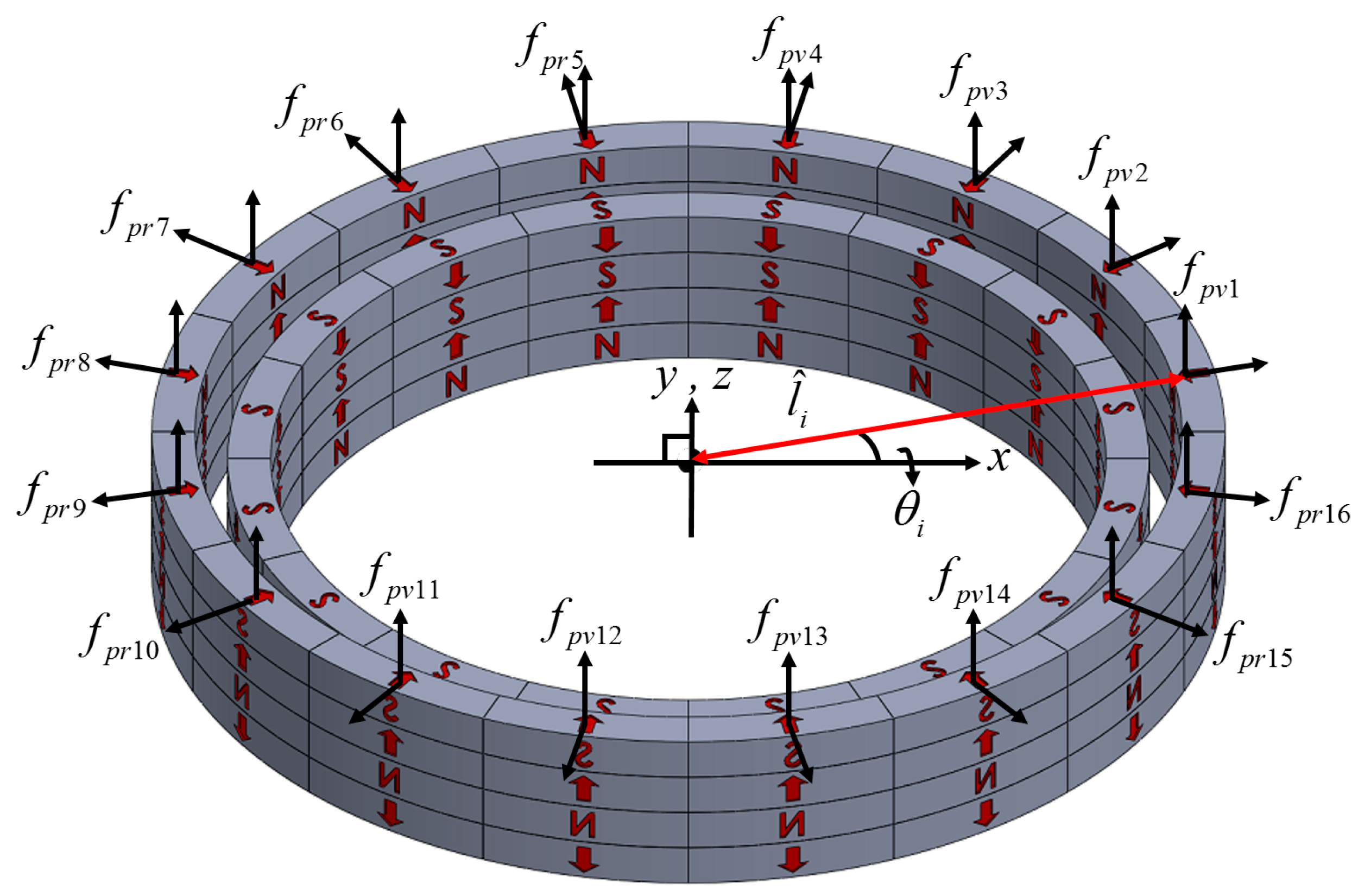
- Magnetic force model of the ring-type PMB with Halbach array configuration is established.
2. System Modeling
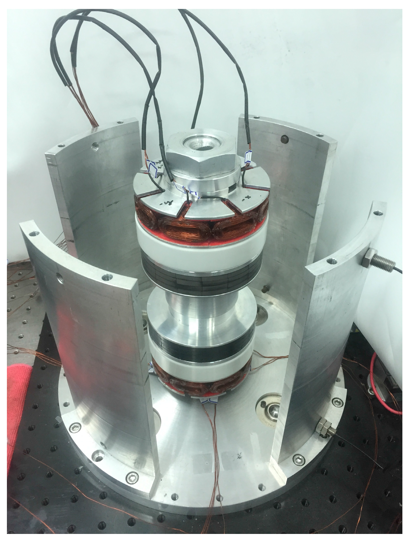
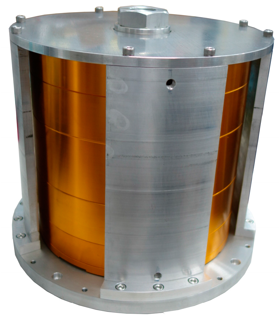
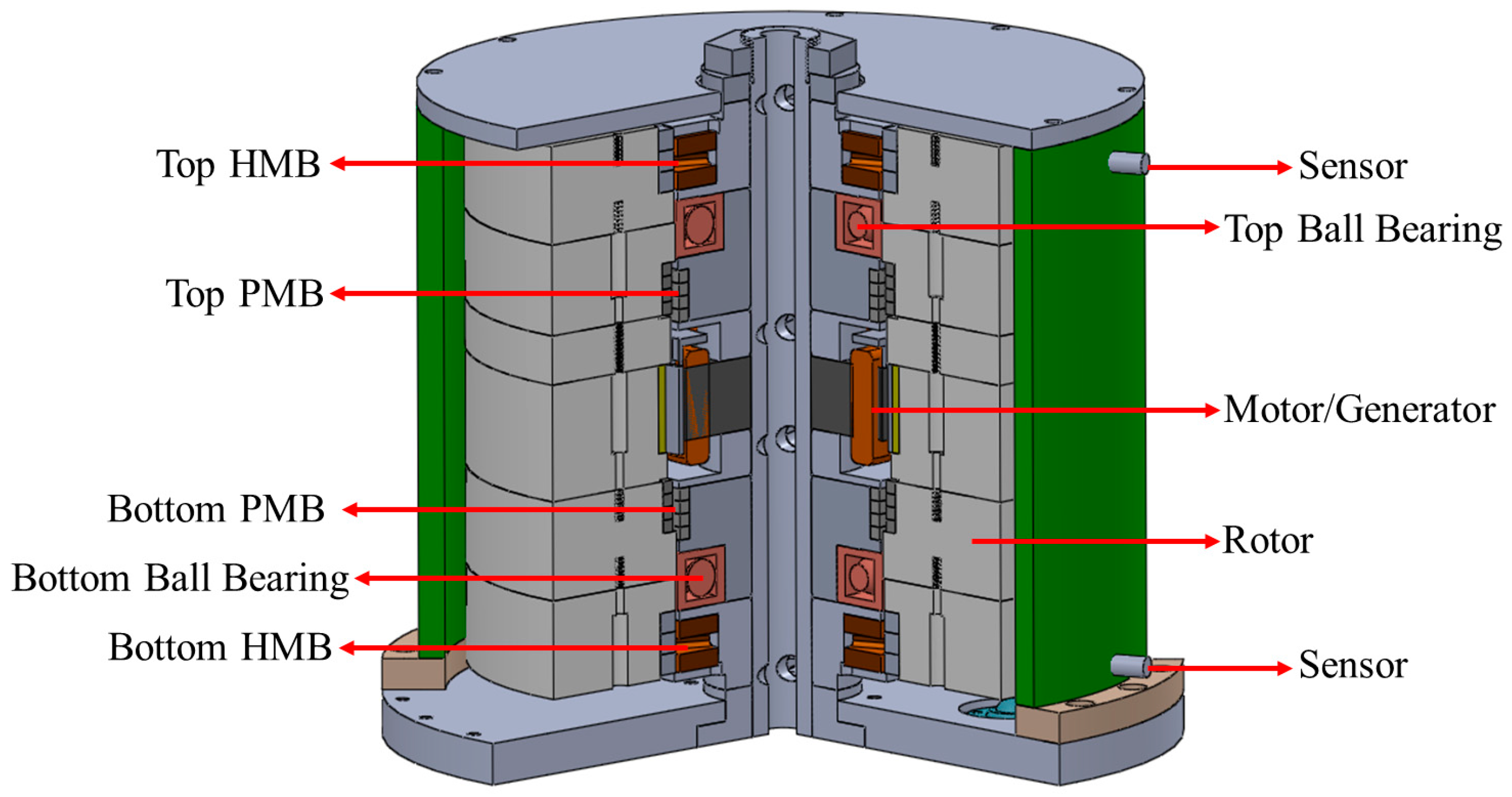
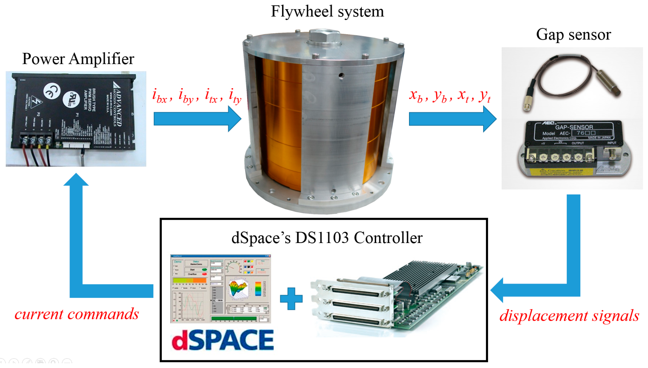
2.1. Description of Flywheel Energy Storage System
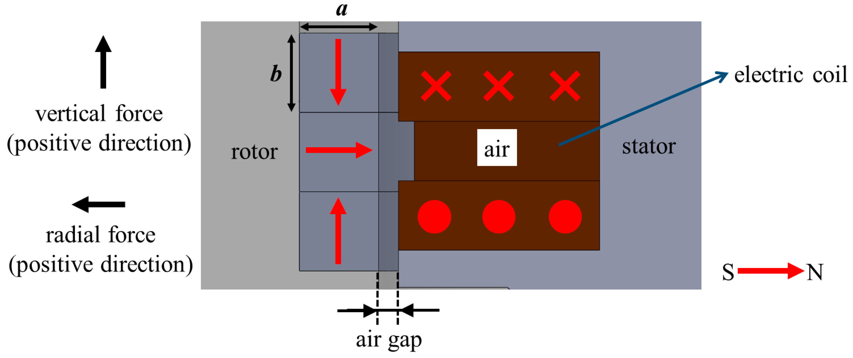
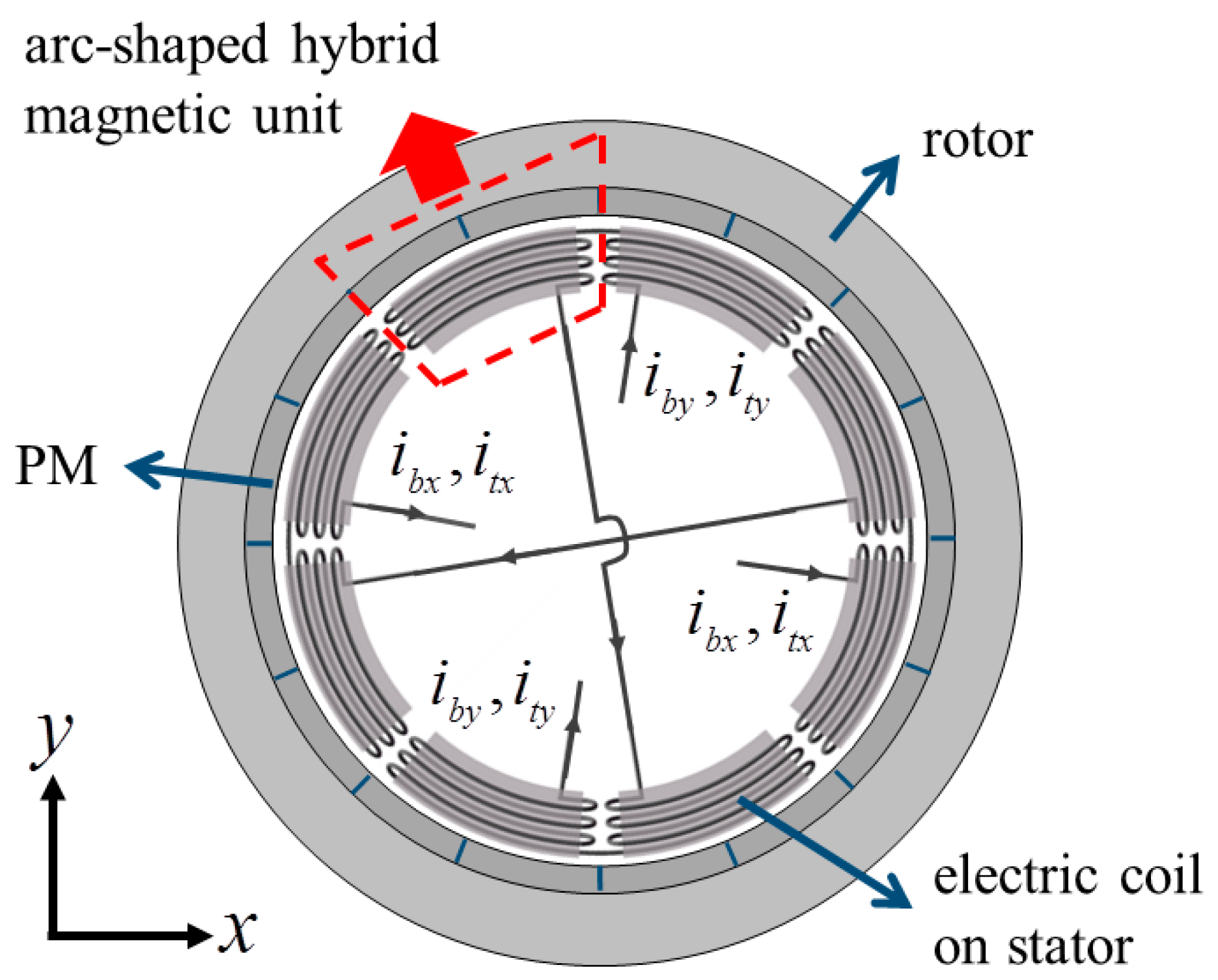
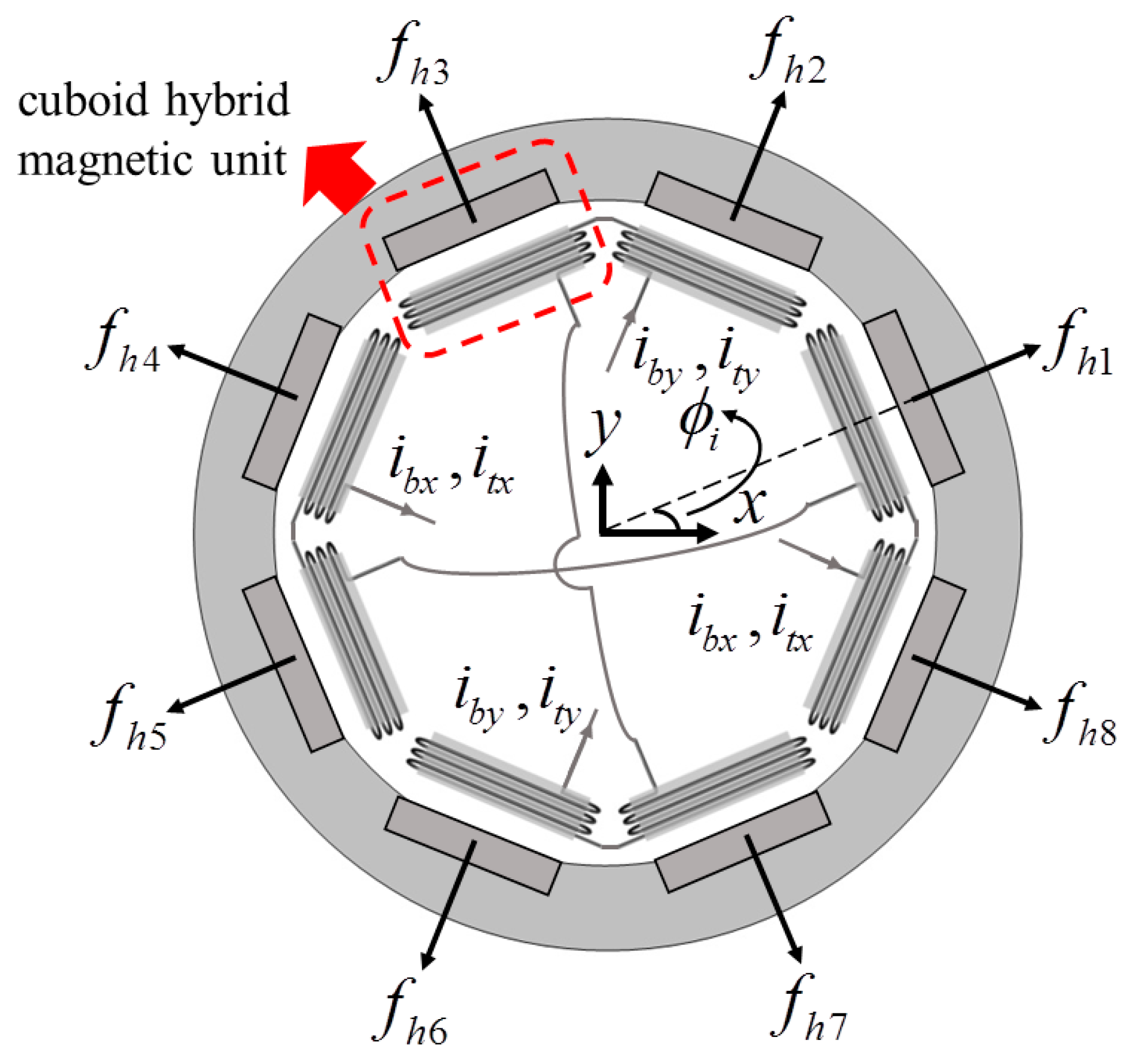
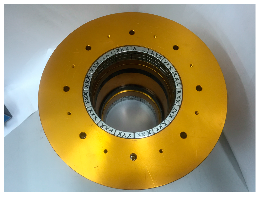
2.2. Hybrid Magnetic Bearing
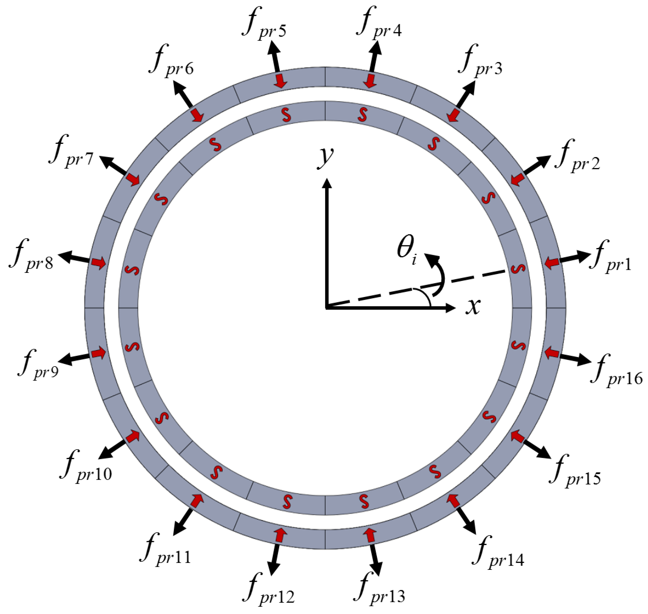
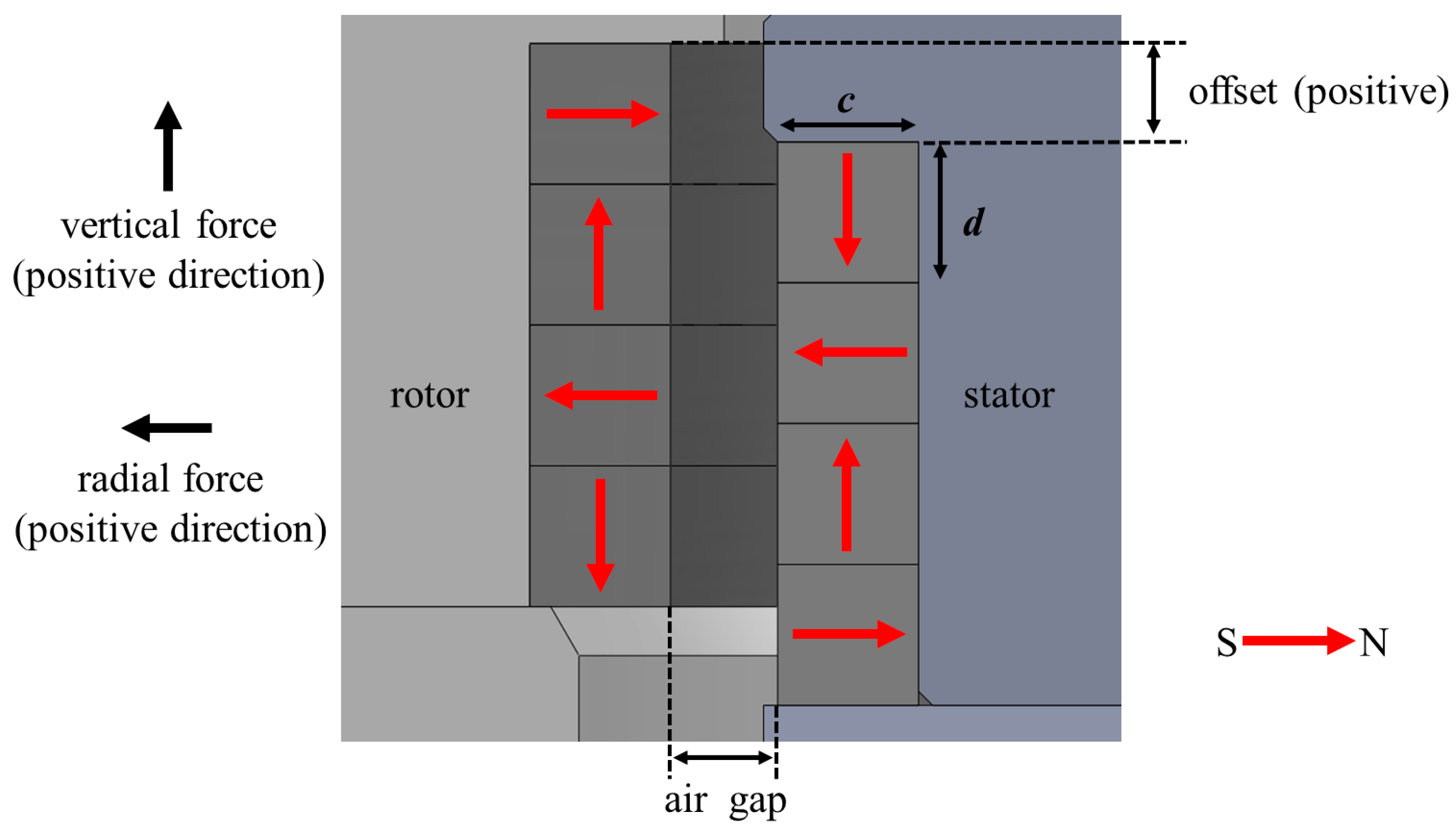
2.3. Passive Magnetic Bearing
2.4. Governing Equation
3. Controller Design
3.1. State Space Model
3.2. Integral Sliding Mode Control
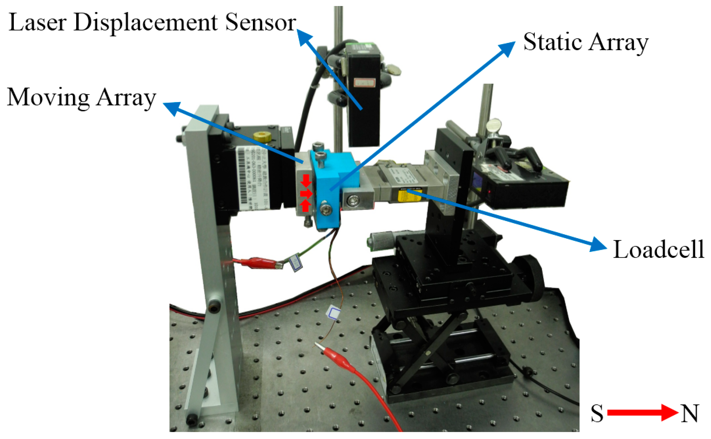
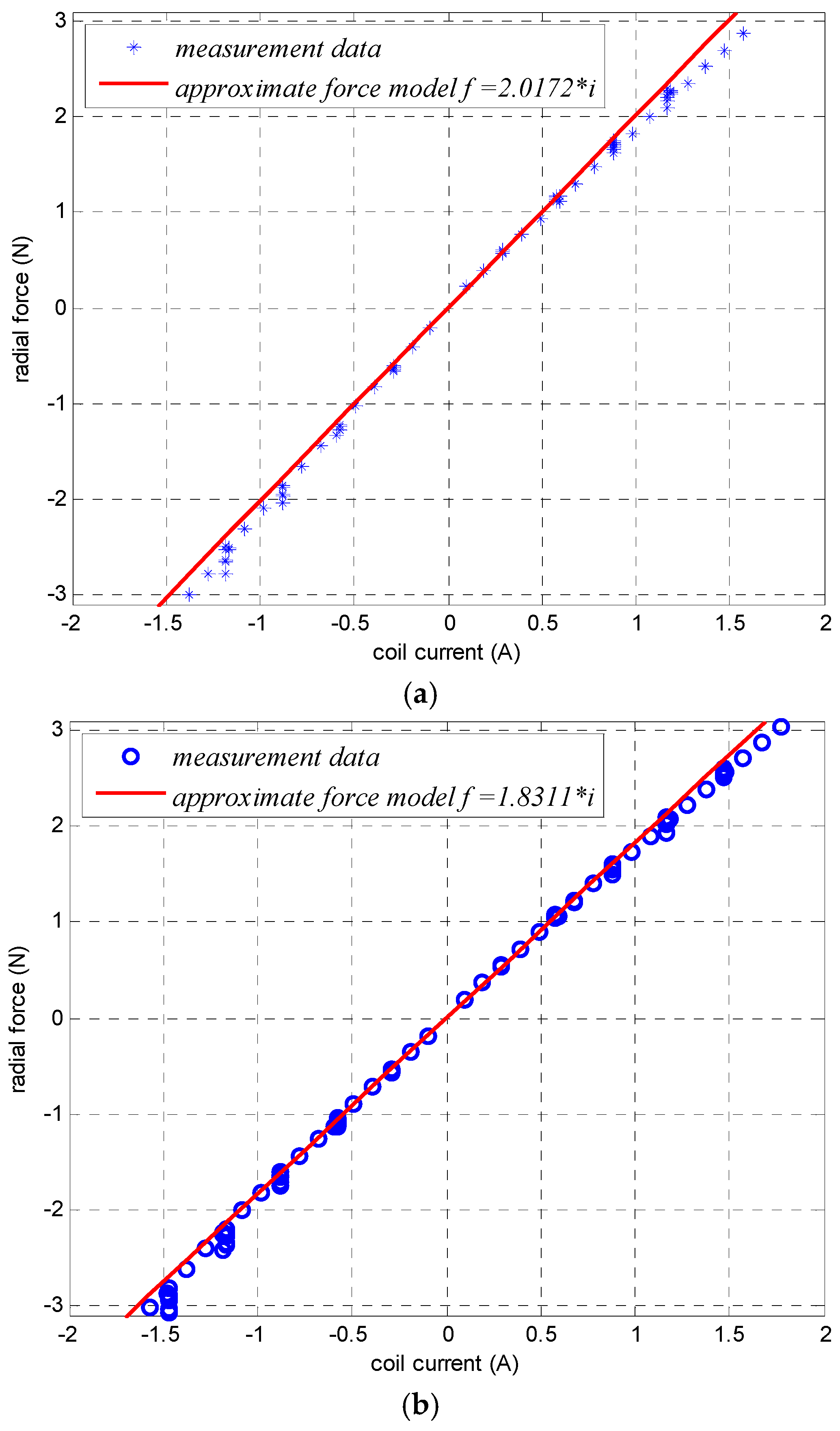
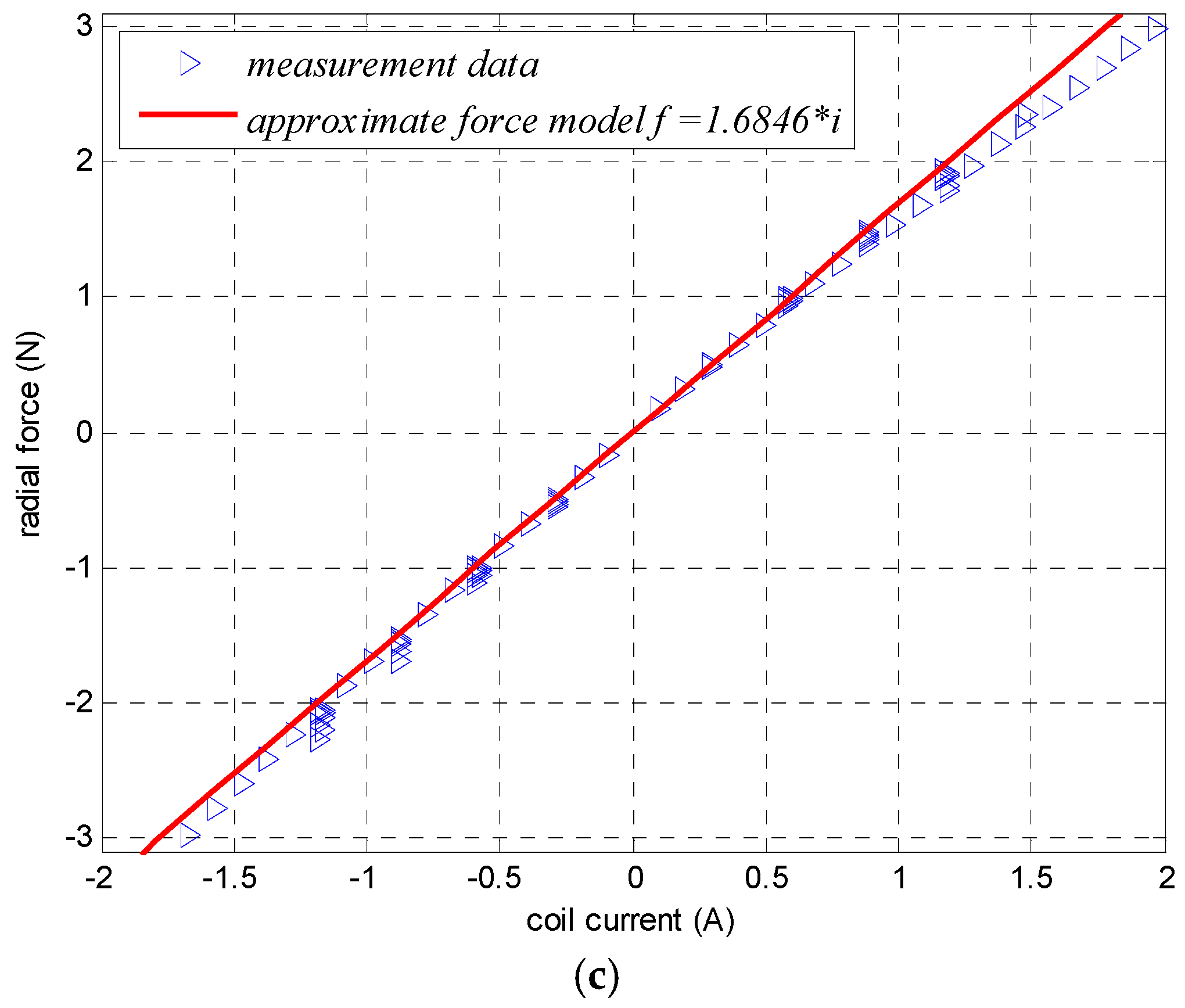
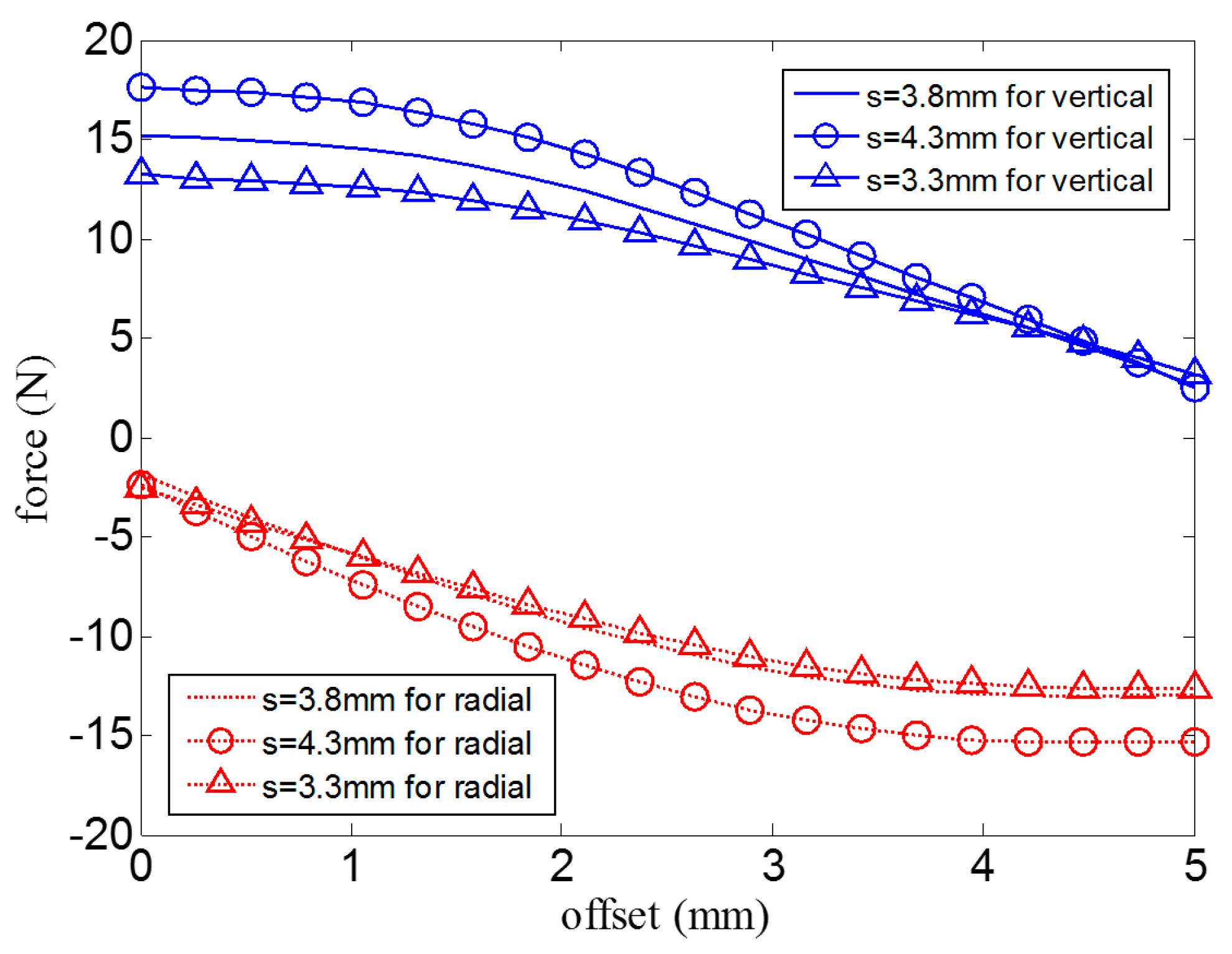
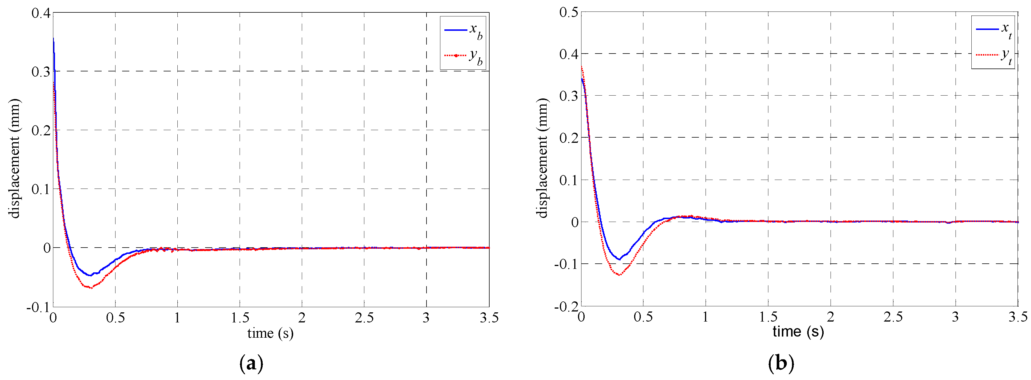
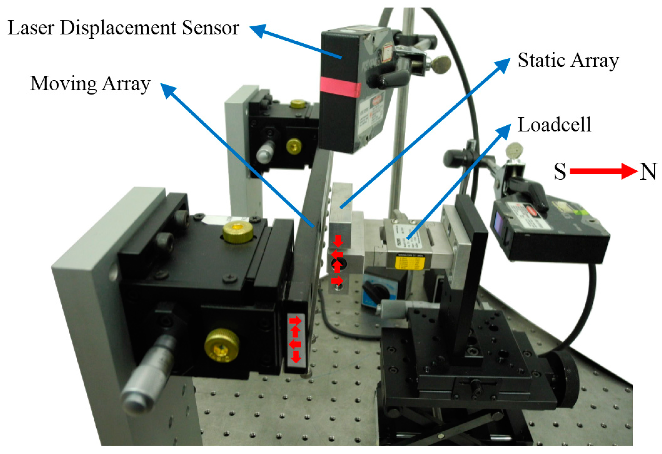
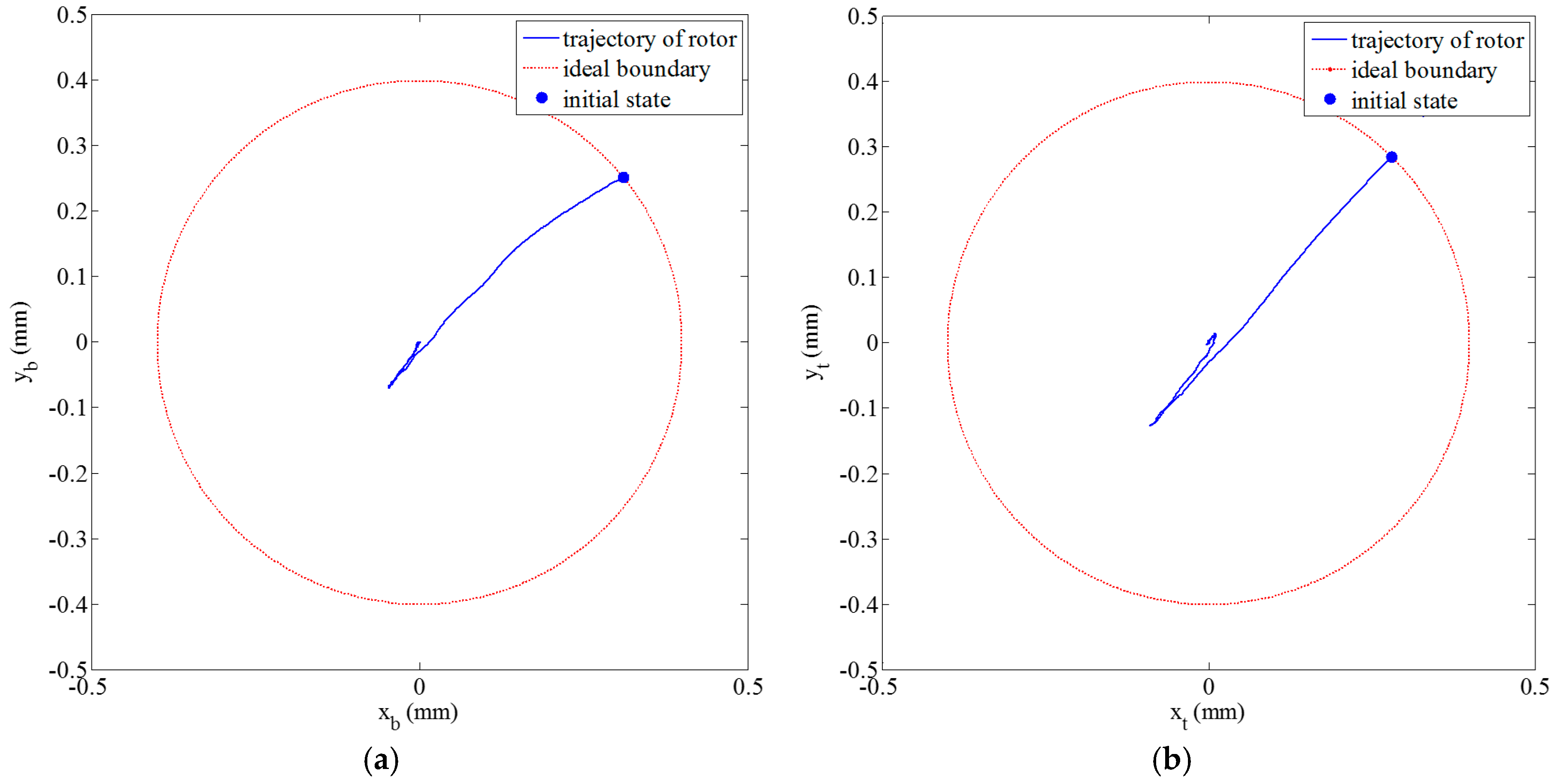
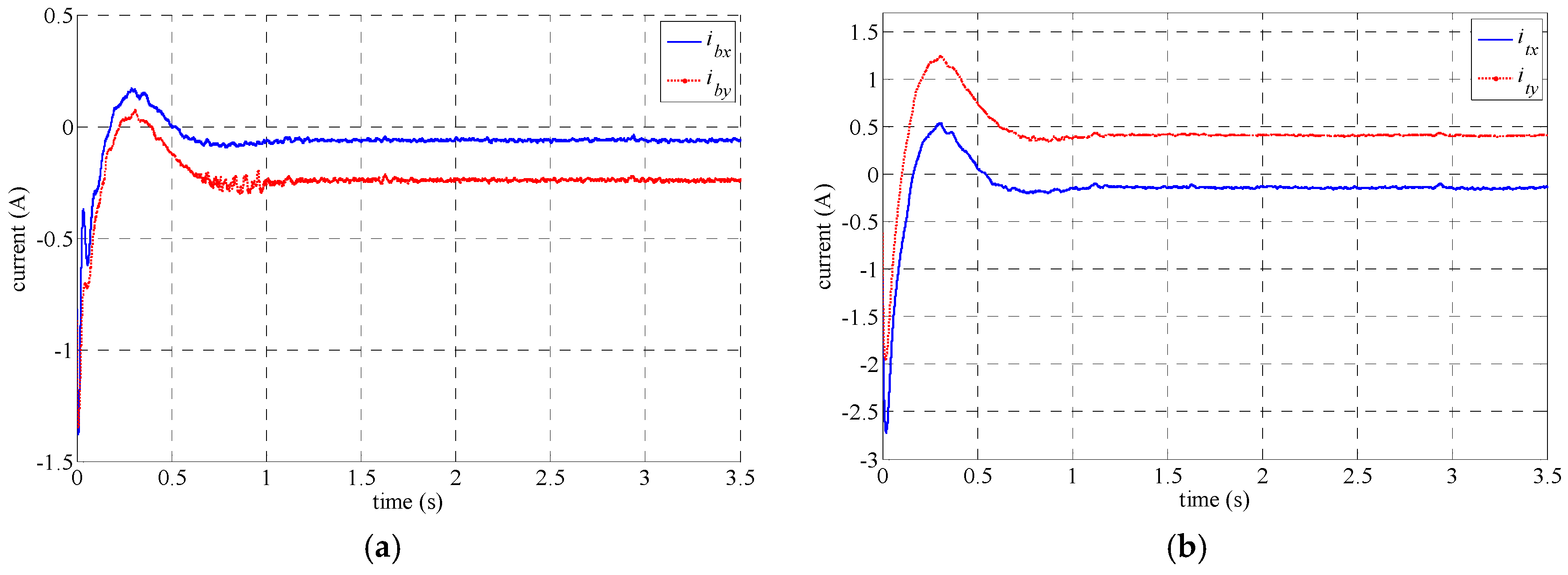
4. Experimental Results
5. Conclusions
Acknowledgments
Author Contributions
Conflicts of Interest
References
- World Energy Council. 2014 World Energy Issues Monitor. 2014. Available online: https://www.worldenergy.org/wp-content/uploads/2014/01/World-Energy-Issues-Monitor-2014.pdf (accessed on 8 August 2016).
- European Commission. The Future Role and Challenges of Energy Storage. 2012. Available online: https://ec.europa.eu/energy/sites/ener/files/energy_storage.pdf (accessed on 8 August 2016).
- U.S. Department of Energy. Grid Energy Storage. December 2013. Available online: http://energy.gov/sites/prod/files/2013/12/f5/Grid Energy Storage December 2013.pdf (accessed on 8 August 2016). [Google Scholar]
- Arnold, S.M.; Salee, A.F.; Al-Zoubi, N.R. Deformation and Life Analysis of Composite Flywheel Disk and Multi-Disk Systems; National Aeronautics and Space Administration, Glenn Research Center: Cleveland, OH, USA, 2001.
- Bolund, B.; Bernhoff, H.; Leijon, M. Flywheel energy and power storage systems. Renew. Sustain. Energy Rev. 2007, 11, 235–258. [Google Scholar] [CrossRef]
- Hansen, G.R.; O’Kain, U. An Assessment of Flywheel High Power Energy Storage Technology for Hybrid Vehicles. Available online: http://www.compositesworld.com/cdn/cms/ORNL Flywheel Assessment for Hybrid Vehicles 2011.pdf (accessed on 8 August 2016).
- Fiske, O.J.; Ricci, M.R. Third generation flywheels for high power electricity storage. In Proceedings of the 19th International Conference on Magnetically Levitated Systems and Linear Drives, Dresden, Germany, 13–15 September 2006.
- Schweitzer, G.; Eric, H. Maslen. Magnetic Bearings; Springer: Berlin/Heidelberg, Germany, 2009. [Google Scholar]
- Abrahamsson, J.; Hedlund, M.; Kamf, T.; Bernhoff, H. High-Speed Kinetic Energy Buffer: Optimization of Composite of Composite Shell and Magnetic Bearings. IEEE Trans. Ind. Electron. 2014, 61, 3012–3021. [Google Scholar] [CrossRef]
- Han, B.; Xu, Q.; Yuan, Q. Multiobjective Optimization of a Combined Radial-Axial Magnetic Bearing for Magnetically Suspended Compressor. IEEE Trans. Ind. Electron. 2016, 63, 2284–2293. [Google Scholar]
- Le, Y.; Sun, J.; Han, B. Modeling and Design of 3-DOF Magnetic Bearing for High-Speed Motor Including Eddy-Current Effects and Leakage Effects. IEEE Trans. Ind. Electron. 2016, 63, 3656–3665. [Google Scholar] [CrossRef]
- Cheng, S.; Day, S.W. Design and Control of Hybrid Magnetic Bearings for Maglev Axial Flow Blood Pump. In Proceedings of the 2010 IEEE/ASME International Conference on Advanced Intelligent Mechatronics, Montreal, QC, Canada, 6–9 July 2010; pp. 187–192.
- Zhang, W.; Hu, Y. A Prototype of Flywheel Energy Storage System Suspended by Active Magnetic Bearings with PID controller. In Proceedings of the Asia-Pacific power and Energy Engineering Conference (APPEEC 2009), Wuhan, China, 27–31 March 2009; pp. 1–4.
- Schuhmann, T.; Hofmann, W.; Werner, R. Improving Operational Performance of Active Magnetic Bearings Using Kalman Filter and State Feedback Control. IEEE Trans. Ind. Electron. 2012, 59, 821–829. [Google Scholar] [CrossRef]
- Rundell, A.E.; Drakunov, S.V.; DeCarlo, R.A. A Sliding Mode Observer and Controller for Stabilization of Rotatinal Motion of a Vertical Shaft Magnetic Bearing. IEEE Trans. Control Syst. Technol. 1996, 4, 598–608. [Google Scholar] [CrossRef]
- Jiang, K.; Zhu, C.; Chen, L. Unbalance Compensation by Recursive Seeking Unbalance Mass Position in Active Magnetic Bearing-Rotor System. IEEE Trans. Ind. Electron. 2015, 62, 5655–5664. [Google Scholar]
- Halbach, K. Design of permanent multipole magnets with oriented rare earth cobalt material. Nuclear Instrum. Methods 1980, 169, 1–10. [Google Scholar] [CrossRef]
- Jang, S.M.; Lee, S.H.; Cho, H.W.; Cho, S.K. Analysis of unbalanced force for high-speed slotless permanent magnetic machine with Halbach array. IEEE Trans. Magn. 2003, 39, 3265–3267. [Google Scholar] [CrossRef]
- Sun, J.; Ren, Y.; Fang, J. Passive axial magnetic bearing with Halbach magnetized array in magnetically suspended control moment gyro application. J. Magn. Magn. Mater. 2011, 323, 2103–2107. [Google Scholar]
- Choi, Y.M.; Gweon, D.G. A high-precision dual-servo stage using halbach linear active magnetic bearings. IEEE/ASME Trans. Mechatron. 2011, 16, 925–931. [Google Scholar] [CrossRef]
- Gruber, W.; Huber, M.; Jungmayr, G.; Amrhein, W. Passive tilt bearings with zero translational Stiffness composed of two permanent magnet rings. In Proceedings of the Twelfth International Symposium on Magnetic Bearings, Wuhan, China, 23–25 August 2010; pp. 21–26.
- Tian, L.L.; Ai, X.P.; Tian, Y.Q. Analytical model of magnetic force for axial stack permanent-magnet bearings. IEEE Trans. Magn. 2012, 48, 2592–2599. [Google Scholar] [CrossRef]
- Bachovchin, K.D.; Hoburg, J.F.; Post, R.F. Magnetic fields and forces in permanent magnet levitated bearings. IEEE Trans. Magn. 2012, 48, 2112–2120. [Google Scholar] [CrossRef]
- Bachovchin, K.D.; Hoburg, J.F.; Post, R.F. Stable levitation of a passive magnetic bearing. IEEE Trans. Magn. 2013, 49, 609–616. [Google Scholar] [CrossRef]
- Wang, N.; Wang, D.; Chen, K.; Wu, H. Research on analytical model and design formulas of permanent magnetic bearings based on Halbach array with arbitrary segmented magnetized angle. J. Magn. Magn. Mater. 2016, 401, 257–264. [Google Scholar] [CrossRef]
- Khalil, H.K. Nonlinear Systems, 2nd ed.; Prentice-Hall: Upper Saddle River, NJ, USA, 1996. [Google Scholar]


| Symbol | Quantity | Value |
|---|---|---|
| m | mass of rotor | 20.76 kg |
| Jt | cross-section radial mass moments of inertia | 0.1720 kg·m2 |
| Jp | polar mass moments of inertia | 0.1793 kg·m2 |
| lb | nominal distances from mass center to the bottom HMB | 92.97 mm |
| lt | nominal distances from mass center to the top HMB | 93.03 mm |
| lbp | nominal distances from mass center to the bottom and top PMB | 42.12 mm |
| ltp | nominal distances from mass center to the bottom and top PMB | 41.88 mm |
| Symbol | Quantity | Value |
|---|---|---|
| l0a | nominal air gap of HMB | 2.0 mm |
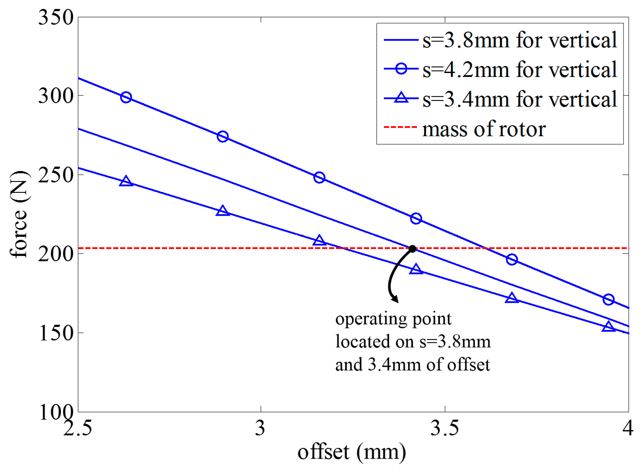
| l0p | nominal air gap of PMB | 3.8 mm |
| z0 | nominal offset of PMB | 3.4 mm |
| N | number of coil turns | 350 |
| a | width of permanent magnet for HMB | 8.00 mm |
| b | height of permanent magnet for HMB | 8.00 mm |
| c | width of permanent magnet for PMB | 5.00 mm |
| d | height of permanent magnet for PMB | 5.00 mm |
| Symbol | Quantity | Value |
|---|---|---|
| k1, k2, k3, k4 | coefficients of AMB | 6.8467 N/A |
| k5, k7 | coefficients of PMB | 14,787 N/m |
| k6, k8 | coefficients of PMB | 5494 N/m |
| k9, k11 | coefficients of PMB | 5460 N/m |
| k10, k12 | coefficients of PMB | 14,819 N/m |
| kmxb, kmyb | coefficients of moments by PMB | 601.18 N |
| kmxt, kmyt | coefficients of moments by PMB | 599.25 N |
| Symbol | Quantity | Value |
|---|---|---|
| b1 | parameter of equivalent control | 30.00 |
| b2 | parameter of equivalent control | 55.00 |
| kc | parameter of switching control | 56.66 |
| ε | parameter of switching control | 0.50 |
© 2016 by the authors; licensee MDPI, Basel, Switzerland. This article is an open access article distributed under the terms and conditions of the Creative Commons Attribution (CC-BY) license (http://creativecommons.org/licenses/by/4.0/).
Share and Cite
Toh, C.-S.; Chen, S.-L. Design, Modeling and Control of Magnetic Bearings for a Ring-Type Flywheel Energy Storage System. Energies 2016, 9, 1051. https://doi.org/10.3390/en9121051
Toh C-S, Chen S-L. Design, Modeling and Control of Magnetic Bearings for a Ring-Type Flywheel Energy Storage System. Energies. 2016; 9(12):1051. https://doi.org/10.3390/en9121051
Chicago/Turabian StyleToh, Chow-Shing, and Shyh-Leh Chen. 2016. "Design, Modeling and Control of Magnetic Bearings for a Ring-Type Flywheel Energy Storage System" Energies 9, no. 12: 1051. https://doi.org/10.3390/en9121051