Article

Evaluation of Strategies to Improve the Thermal Performance of Steel Frames in Curtain Wall Systems

Department of Architecture, Ajou University, Suwon, Gyeonggi-do 443-749, Korea
*
Author to whom correspondence should be addressed.
Energies 2016, 9(12), 1055; https://doi.org/10.3390/en9121055
Submission received: 26 September 2016 / Revised: 14 November 2016 / Accepted: 6 December 2016 / Published: 14 December 2016
(This article belongs to the Special Issue Energy Conservation in Infrastructures 2016)

Abstract

:
Recently, metal curtain wall systems have been widely used in high-rise buildings due to many advantages, including being lightweight, rapid construction, and aesthetic features. Since the metal frame may lead to lower energy performance, thermal discomfort, and condensation risk due to the high thermal conductivity, its thermal performance can be important for the improvement of the overall thermal performance of the curtain wall system, as well as the energy efficiency of the building envelope. This study aims to evaluate variety of design strategies to improve the thermal performance of steel curtain wall frames. Five base cases and three further steps were selected for two different head profile shapes based on a state-of-the art technology review, and their thermal transmittances were calculated through simulations according to the ISO 12631 standard which is an international standard for calculating thermal transmittance of curtain wall system. Measured results that were obtained from hot-box tests were compared with the calculated results to validate the simulation method of this study. The shape of the head profile did not strongly influence the overall thermal transmittance, and the choice of strategies for the rabbet space was more important. More effective strategies could be decided according to the steps for variation development. This result can serve as a guideline for the design of high-performance curtain wall frames.

1. Introduction

Curtain wall systems are widely used in high-rise buildings due to many advantages, including being lightweight, their high quality in manufacturing, rapid construction, and aesthetic features [1,2,3,4,5]. A curtain wall usually consists of metal frames and infills, such as glazing, metal panels, or thin stone. Glazing is the most typical infill since it provides a modern and aesthetically pleasing appearance, as well as benefits regarding daylighting and the view. Large portions of glass and metal may, however, lead to a number of potential problems, such as a lower energy performance, thermal discomfort, and a condensation risk, all of which are due to high thermal conductivities [1,5]. In terms of the performances of glass, low-e coatings, multiple panes, the inert-gas infill, and other cutting-edge technologies have significantly reduced the overall U-value of the glazing unit [1,3]. Curtain walls consist of a variety of subsidiary components including gaskets, sealants, and cavity fillings for the improvement of the thermal performance, air tightness, and water tightness [1]. The thermal performance will vary according to the material properties of these components and the complicated joint configuration, and the amount of reduction can be lowered by the performance of the metal frame. The design details, material properties, and joint configuration of the metal frame significantly affect the thermal performance of a curtain wall building [5,6,7,8,9,10]. Therefore, a wide range of research has been conducted on the development of the design details and components to improve the thermal performance of the metal frame.
Metal curtain walls can be classified according to the framing material that is used. Aluminum and steel are the two primary framing materials of curtain walls. For many years, aluminum frames have been widely used for the advantages of light weight, design flexibility, and corrosion resistance [3,6]. Recently, steel has re-emerged as a high-performance material in terms of glazed curtain walls due to advances in manufacturing technologies. Steel curtain walls have many advantages, including an ability to support larger spans of glass, narrower frame designs, and the provision of high thermal performances and a longer-term durability [3,6,10]. Since steel is approximately three times stiffer than aluminum, it allows for not only larger areas of uninterrupted glass with less framing, but also narrower frame profiles and larger free spans [10]. In addition, one of the most important advantages of steel over aluminum is its thermal performance. Since the conductivity of steel is lower than that of aluminum, it is possible to reduce the heat gain and loss through the curtain wall frame, as well as the risk of interior condensation on the frames, and this is combined with narrower frame profiles. Although the steel frame has several advantages that are due to its physical characteristics, it is still necessary to develop and apply various technologies to improve the thermal performance of the steel frame curtain wall.
The purpose of this study is to evaluate different strategies to improve the overall thermal performance of the steel frames in curtain wall systems. A variety of design strategies were selected based on an overview of recent technologies, and their effects on the thermal performance of the curtain wall were analyzed in detail. Measured results that were obtained from hot-box tests were compared with the calculated results to validate the simulation method of this study. In addition, heat transfer simulations were carried out to investigate the effect of design strategies on the thermal transmittances of the curtain wall.

2. Evaluation Method and Validation

2.1. Overview of Standards for Evaluating the Thermal Performance of Curtain Walls

The thermal performance of curtain walls can be determined by measurement or calculation in accordance with the standards for windows and doors. Since an international standard for the measurement of the thermal transmittance of curtain-wall systems (UCW) does not exist, the standards for windows and doors, including ISO 12567-1 [11], ASTM C1199-09 [12], AAMA 1503-09 [13], NFRC 102-2010 [14], and KS F 2278 [15], are generally used for this purpose. According to these international or national standards, the thermal transmittance, or the U-value, of a test specimen is measured by means of the calibrated or guarded hot-box method for which the test conditions are similar to the actual indoor and outdoor environments and conditions of windows and doors. These standards are designed to provide both standardized tests, which enable a fair comparison of different products, and specific tests for products for practical application purposes [11]. The former specifies standardized specimen sizes, and its measurement result is usually issued for the certificates of the window energy rating systems in many countries since it allows consumers to compare the thermal performances of different products under the same conditions, whereby they can subsequently select superior products based on the comparison.
While the measurement offers relatively accurate values, as it involves a performance evaluation for actual specimens, it is too costly and time-consuming to apply for the evaluation of every design alternative at the development stage of new products. For this purpose, a numerical simulation can be preferable because it requires less time and expense. Simulation methods are also accepted by window energy rating schemes for the rating and certification of window products [16]. For example, the U.S. National Fenestration Rating Council (NFRC) allows for the rating of windows not only by the measurement, but also by the calculation from its approved simulation software [14]. The window energy rating system in Korea allows not only the measured thermal transmittance according to KS F 2278 [15], but also the calculated results according to ISO 15099 [17]. Taking into consideration the time and cost, it has become increasingly popular in both research and industry to evaluate the thermal performance of windows based on the calculation method and the use of reliable standards and simulation programs.
ISO 15099 [17], ISO 10077-1 [18], and ISO 10077-2 [19] are generally used to calculate the thermal transmittances of windows and doors. These standards, originally developed for the evaluation of windows, have also been used for curtain wall systems because of the absence of specific standards for curtain wall systems. However, curtain walls differ from windows in that they have a much larger continuous glazing portion, a configuration and components of a greater complexity, and heat flow at the joints [5,7]. Therefore, ISO 12631 [20] was recently developed to specify a procedure for the calculation of the thermal transmittance of curtain wall systems.
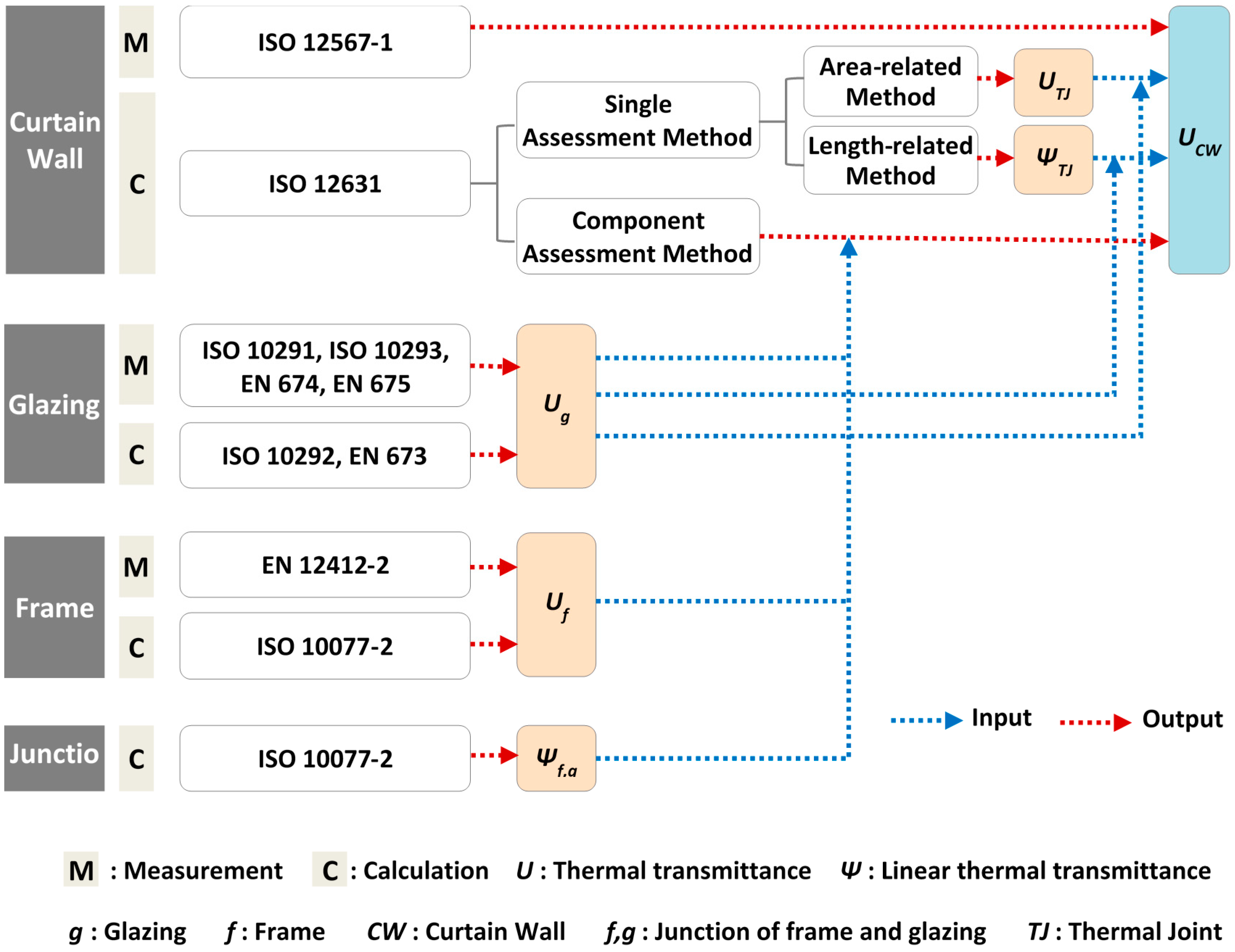
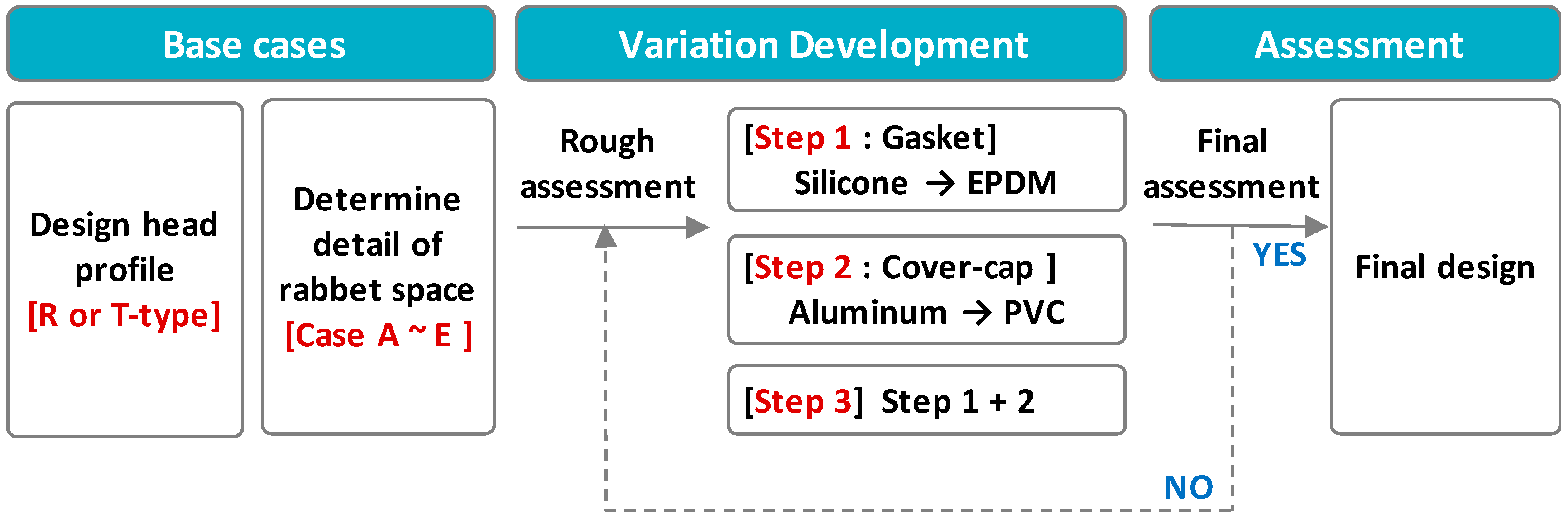
This standard can be used to calculate the thermal transmittance of curtain wall systems by considering the heat transfer through the glazed area, the frame area, and the panel area, as well as the thermal interaction between them. Two different methods were specified to calculate the thermal transmittances in ISO 12631 [20], as follows: the single assessment method and the component assessment method. In the single assessment method, the overall thermal transmittance of the curtain wall was calculated by area according to a weighting of the U-values of the thermal joints and the filling elements. The additional heat flow rate through the thermal joints was considered in terms of both the area-related thermal joint transmittance and the length-related linear thermal joint transmittance. The component assessment method divides the representative element into areas of different thermal properties. The overall UCW was calculated by area-weighting the U-values of these elements with additional correction terms; linear thermal transmittance that describes the thermal interaction between these elements. The determining process of the overall UCW is shown in Figure 1. The calculated results according to this standard can be used for a comparison of the thermal transmittances of different types of curtain wall systems, or as a part of the input data for calculating building energy consumption.

2.2. Calculation Method and Validation

Since the measurement of the UCW of multiple design alternatives is too costly and time-consuming in the early stage of development, their performances were evaluated according to the calculation method. Prior to the evaluation of the alternatives, the calculation method was validated by comparing the calculated and measured UCW values of the test specimens according to ISO 12631 [20] and KS F 2278 [15], respectively. ISO 12631 [20] specifies that testing according to ISO 12567-1 [11] is an alternative to its calculation method, and KS F 2278 [15] is generally equivalent to ISO 12567-1 [11], except for a minor difference of the boundary conditions, as shown in Table 1.
The steel curtain wall can be classified into the roll-formed frame and the welded frame, depending on the manufacturing method [10]. In this study, two curtain walls with the roll-formed frames and one with the welded frame were selected for the validation, as shown in Table 2.
The measurements were carried out according to KS F 2278 [
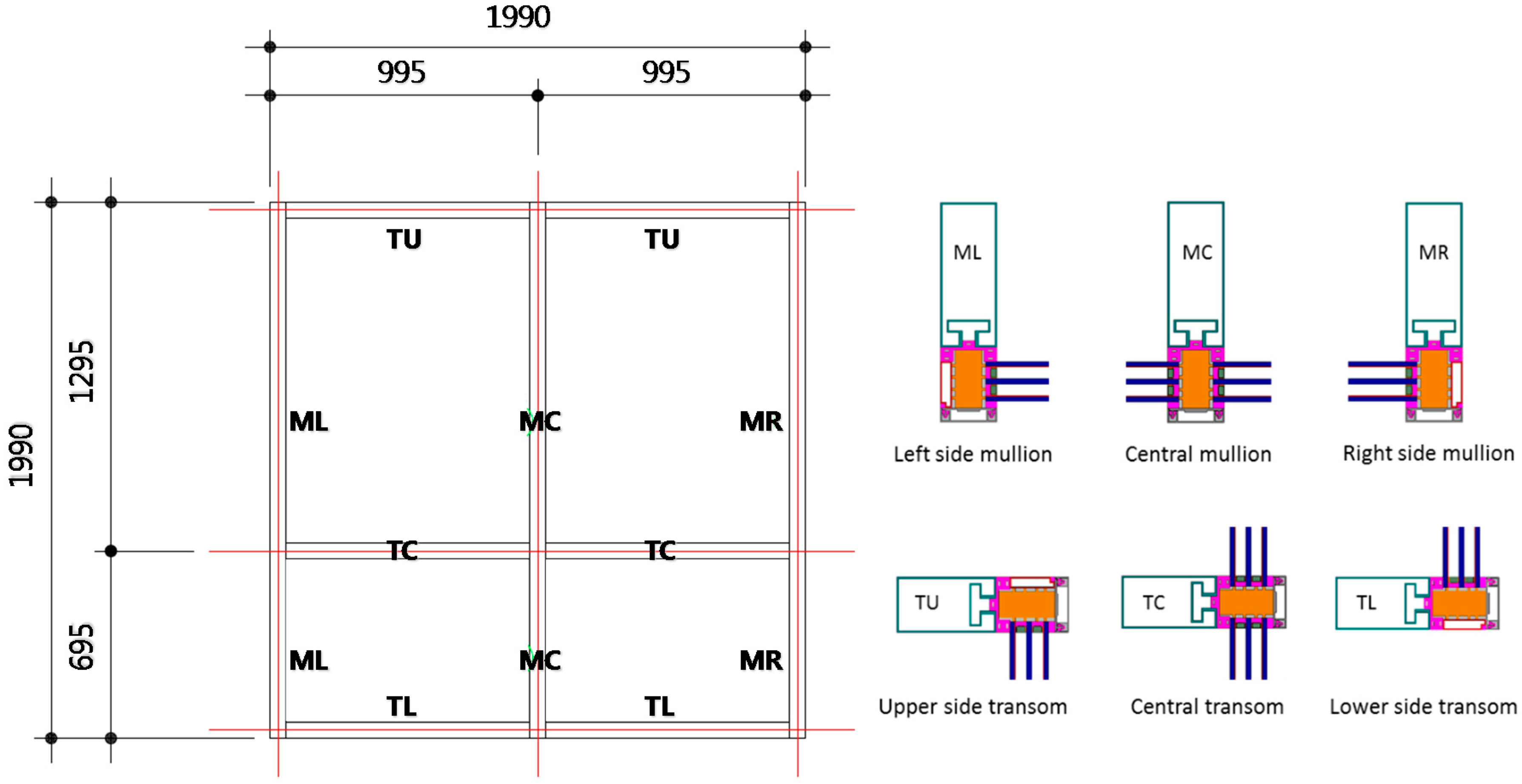
15] in the test facility of the Korea Institute of Civil Engineering and Building Technology, which is accredited by the Korean Laboratory Accreditation Scheme. Considering the hot-box metering area (2000 mm × 2000 mm), the dimensions of the test specimens were set up as 1990 mm × 1990 mm, as shown in Figure 2. The perimeter joints between the surrounding panel and the specimen were sealed on both sides with caulking material. The tests were performed under steady-state conditions at the temperatures of 20 °C and 0 °C at the indoor and outdoor sides, respectively. The air flow was also adjusted according to the standard, as specified in Table 1. The surface temperatures of the specimen were measured with T-type thermocouples at the center of nine parts of the specimens.
To calculate UCW by the calculation method, the curtain wall was divided into six cross-sections for modeling in accordance with ISO 12631 [20], as shown in Figure 2. The heat flow rates through the glazing, frame, and joints were calculated using Physibel Trisco 12.0 w (Maldegem, Belgium), a three-dimensional, steady-state heat transfer analysis program that conforms to ISO 10211 [21] and ISO 10077-2 [19]. In the simulations, the indoor and outdoor temperatures and the air flow conditions were also set up according to KS F 2278 [15] so that the calculated and measured values could be compared. Table 3 shows the thermal conductivities of the materials that were used in the numerical simulation, which were obtained from manufacturers or ISO 10077-2 [19]. First, the UM, UT, and Ug were evaluated according to ISO 10077-2 [19] and ISO 10077-1 [18]. Second, the UTJ and ΨTJ were evaluated according to ISO 12631 [20] for the simple-assessment method, and the ΨM,g and ΨT,g were also evaluated according to ISO 10077-2 [19] for the component-assessment method. Lastly, the UCW was calculated according to the area-related single-assessment method, the length-related single-assessment method, and the component-assessment method specified in ISO 12631 [20].
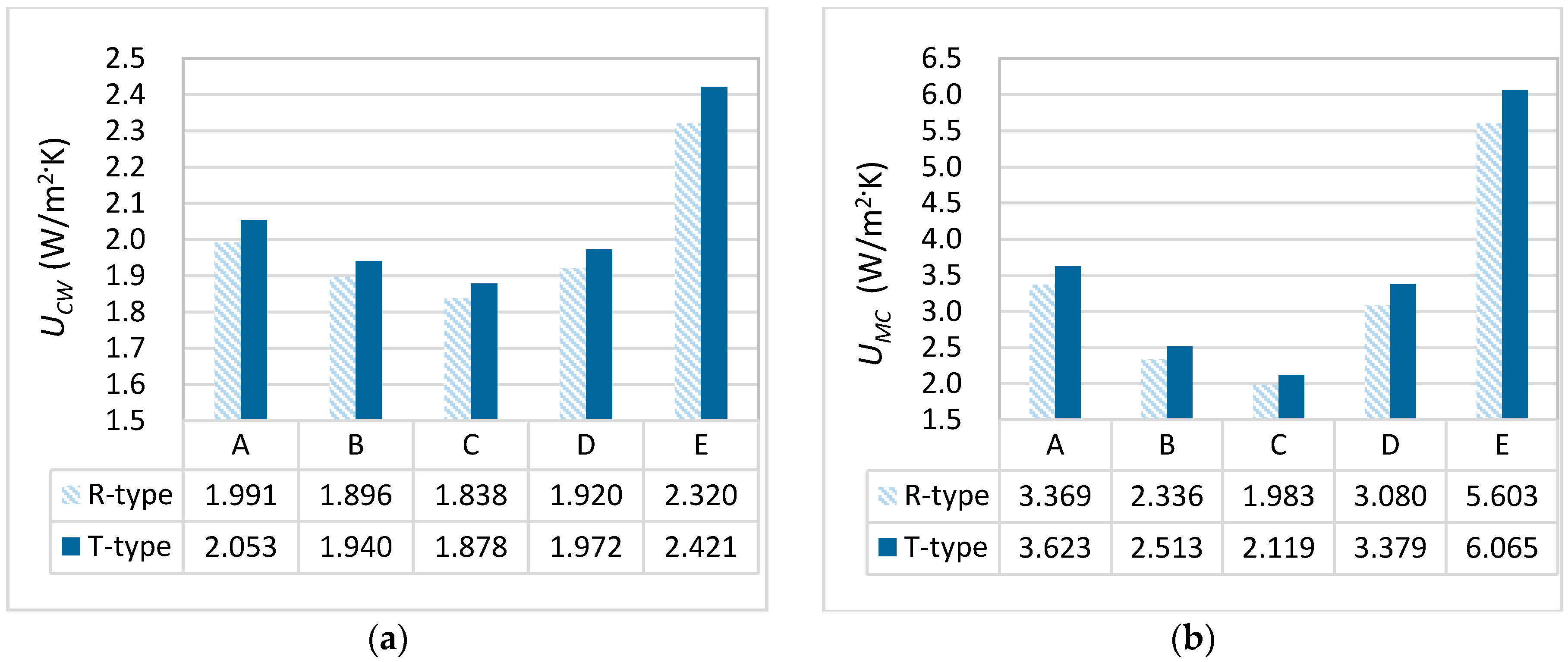
Table 4 shows the comparison of the measured and the calculated UCW values. The thermal transmittances of specimens 2 and 3 are much lower than that of specimen 1, since they were applied with high thermal performance materials, such as triple low-e coated glazing, ethylene propylene diene monomer (EPDM) filling, and the polyamide cap. There is no significant difference between specimens 2 and 3. There is a sound agreement between the overall measured and calculated values, and the differences range from 0.3% to 3.8%.

3. Evaluation Cases Setup

A steel curtain wall frame can be defined by the following three parts, as shown in Figure 3: the head part, which is the warm side of a façade; the body part into which the infills (glazing and opaque panels) are inserted; and the cover part that faces the cold side of a façade. The gaskets and sealants for weather-proofing and air-tightness are installed in the connections of the three parts. Since the head part and the cover cap are exposed to the inside and the outside, respectively, they have been designed in a variety of shapes for aesthetic purposes [10].
According to the state-of-the art review of the steel curtain wall products on the market, a few of the common strategies for the overcoming of weak thermal performances were categorized, as shown in Figure 4. One of the most common strategies is the use of materials with a thermal conductivity that is relatively lower than that of the conventional materials; for example, an EPDM (ethylene propylene diene monomer) gasket was inserted in high-performance curtain-wall systems instead of a silicon gasket, as shown in Figure 4a [22,23,24,25]. Additionally, metal head profiles can be overlaid with PVC (polyvinyl chloride), or stainless-steel cover caps were applied instead of aluminum cover caps, as shown in Figure 4b [26] or Figure 4c [22,24,26]. Another important strategy was a reduction of the heat loss through the rabbet space; for example, the rabbet space can be filled with polymers with a low thermal conductivity, as shown in Figure 4d [22,24,26], or a PVC isolator can be attached to the external gasket side for the thermal performance as well as weather-proofing [26]. Figure 4e [27] shows another way to reduce the heat loss through the use of thermal breaks that are usually made up of a polyamide bar or a polyurethane-filled aluminum bar.
Based on the state-of-the-art review of the technical cases, base cases and their variations were set up and drawn for more alternatives, as shown in Figure 5, to provide engineers with choices, depending on the given situation.
First, two design alternatives, the rolled-formed type (R type) and the T-bar welded type (T type), were configured for a consideration of the variety of head profile shapes, and then the cases A–E were configured depending on the details of the rabbet space. Case A is a curtain wall frame that is composed of a large rabbet space without separate infill or thermal breaks. Cases B and C involve a filling of the air cavity with EPDM, either partially or entirely, while Cases D and E are curtain-wall systems to which thermal breaks are applied. Specimen 1 was used in the validation and was simplified for its use as a reference frame design for the base cases. Table 5 shows descriptions of the base cases according to the head-profile and rabbet space details.
The variation development with different materials was conducted according to Steps 1–3. Step 1 is a stage where the gasket material is changed from silicone to EPDM. Step 2 is another alternative where the cover cap’s material is changed from aluminum to PVC. Lastly, in Step 3, the changes of Steps 1 and 2 are applied.
The thermal transmittances of the base cases and their variations were evaluated according to the calculation method that is based on ISO 12631 [19], the validation of which is mentioned above. Of the two evaluation methods that are specified by ISO 12631 [19], the component-assessment method that considers all of the members with different thermal properties was used to analyze the UCW. This method allows for a more minute evaluation than the single-assessment method, which can be used to analyze all types of curtain wall systems, but is not applicable to structural glazing, rain screens, and structural sealant glazing. The size, indoor and outdoor boundary conditions, and material properties of the curtain wall systems for the evaluation are shown in Figure 2, Table 1 and Table 4, respectively.

4. Results and Discussion

4.1. Comparison According to the Head Profile Shape and Rabbet Space Details

The effect of the head profile shape on the UCW was analyzed. UMC was also analyzed because it is directly related with the thermal bridge and condensation risk of the frame [1,5,7]. Figure 6 shows the comparison of the calculated UCW and UMC of Cases A–E according to the shape of the head profile. For all of the cases, the R-type head profile showed a relatively higher thermal performance than the T-type head profile, but the difference between the two shapes is not greatly significant. The difference ratios ranged from 2.14% (Case C) to 4.13% (Case E) for the UCW, and from 6.87% (Case C) to 9.72% (Case E) for the UMC. A similar result was also obtained for the test specimens for the simulation validation in Section 2.2. The measured UCW of Specimen 2 with the roll-formed head profile, 1.05 W/m2·K, is lower than that of Specimen 3 with the T-bar-welded head profile, 1.09 W/m2·K. In general, under the same configurations and specifications of the body part and cover cap, the R-type head profile is slightly more advantageous than the T-type head profile in terms of thermal performance; however, since the difference is not major, designers may choose any of the head profiles from an aesthetic perspective.
In view of the details of the rabbet space, Cases B and C with EPDM are more advantageous than Cases D and E with thermal-break profiles. By filling the entire rabbet space with EPDM, the thermal transmittance of a central mullion frame can be reduced from 3.369 W/m2·K to 1.983 W/m2·K (41.1% reduction) for the R-type head profile, and from 3.623 W/m2·K to 2.119 W/m2·K (41.5% reduction) for the T-type head profile. This improvement of the thermal performance of the mullion and the transom also resulted in the reduction of the UCW, and it would be more advantageous if the proportion of the frame area that is against the glazing area is higher. Case E, however, showed an even higher thermal transmittance than Case A without any strategies for the rabbet space. It seems that much more heat was transferred through the aluminum profile for the polyurethane filling and the rabbet fixing; therefore, unless there is any other reason regarding the structural stability or the cost, a restriction of the use of aluminum thermal breaks as much as possible in steel curtain wall systems seems reasonable in terms of the thermal performance.

4.2. Comparison of Thermal Transmittances According to the Gasket and Cover Cap Materials

The effect of different materials for the gasket and the cover cap was analyzed by comparing the UCW and UM of the variations for Steps 1–3. Figure 7 presents the variations of the UCW with the change of materials for the R-type and T-type curtain walls. By changing the materials for the gasket and/or the cover cap, the UCW can be decreased by approximately 12.1% and 13.2% on average for the R-type and T-type head profiles, respectively. Changing materials for the gasket (Step 1) or the cover cap (Step 2) produced a much greater impact on the improvement of the thermal performance than the changing of the details of the rabbet space (Cases B through E). The UCW of Case A was decreased by approximately 14.6% and 12.0% through the application of Steps 1 and 2, respectively. As was expected, Step 3 showed the lowest thermal transmittance for all of the cases since materials with a lower thermal conductivity were applied for both the gasket and the cover cap. The reduction rate is the greatest for Case E, which has an internal aluminum profile with the polyurethane thermal break in the rabbet space.
There was a difference between the effects of Step 1 and Step 2 according to the cases. For Cases A, B, and C with the R-type head profile, the UCW is much-more decreased at Step 1 by approximately 12.0%, 11.7%, and 11.9%, respectively, when compared with Step 2, which was decreased by approximately 10.1%, 9.0%, and 7.4%, respectively. On the other hand, Cases D and E showed a greater improvement effect in Step 2, as shown in Table 6. If only one component between the gasket and the cover cap can be changed by the further design of the development stage, it would be more effective to change the gasket materials from silicon to EPDM for Cases A, B, and C, while it is more effective to change the cover cap materials from aluminum to PVC for Cases D and E.
To analyze this difference between the effects of Step 1 and Step 2 according to the cases, the heat flow profiles of the representative mullion sections were investigated, as shown in Figure 8. Since the heat flow was bypassed through the joints of the frame and glazing, a thermally-improved gasket is more effective for a reduction of the heat flow between the frame and the edge of the glazing for Cases A, B, and C; meanwhile, the heat flow was distributed with the overall frame in Cases D and E, and the PVC cover cap is a more effective way to control the heat flow through the polyamide-bar or aluminum profile. Throughout all of the cases and variations, the UCW of the R-type is always lower than that of the T-type, but the values are not very different from one another. This indicates that the improvements to the body or the cover part are more effective than the head profile design.

5. Conclusions

Recently, the steel frame has re-emerged as a high-performance material for glazed curtain walls due to advances in the manufacturing technology field. In spite of the many advantages, a steel frame requires different strategies to achieve a sound thermal performance due to manufacturing and processing limitations. In this paper, the effect of different design strategies on the thermal performance of the steel curtain wall frame was evaluated according to the simulation method. The simulation method was validated by a comparison of the measured and calculated thermal transmittances for three different curtain wall specimens. For roll-formed and T-bar-welded frame profiles, five base cases and additional variations were set up for an evaluation based on the state-of-the art review. This study can be summarized as follows: (1) The head profile types did not strongly influence the UCW, and the difference ratio ranged from 2.14%–4.13%; (2) The improvement strategies for the rabbet space was rather effective than changing the head profile type. Cases B and C with rabbet space infill were effective to decrease the thermal transmittance, but Cases D and E with internal thermal breaks showed even higher thermal transmittance than Case A; (3) There was a difference between the effects of a thermally-improved gasket (Step 1) and the cover cap (Step 2), depending on the initial strategies for the rabbet space. The results of this study can be referred to for the selection of more valid and more effective strategies in the achievement of high thermal performance in steel curtain wall frames. It is also expected that steel frames with these strategies can not only reduce the thermal bridge and condensation risk, but also enhance the occupants’ thermal comfort and health.

Acknowledgments

This work was supported by a National Research Foundation of Korea (NRF) grant funded by the Korea government (MSIP) (No. 2014R1A2A2A01007405).

Author Contributions

Ji Hyun Oh and Hyun Jung Yoo performed the simulations and experiments; Ji Hyun Oh wrote the paper; Sun Sook Kim conceived the concept of this research and wrote the paper.

Conflicts of Interest

The authors declare no conflict of interest.

References

  1. Yoo, H.J.; Yang, S.W.; Kim, S.S. Comparison of Thermal Transmittances of Curtain Walls by Different Ratio of the Frame Area. In Proceedings of the 11th REHVA World Congress Clima 2013—Energy Efficient, Smart and Healthy Buildings, Prague, Czech Republic, 16–19 June 2013.
  2. No, S.T.; Kim, K.S.; Jung, J.S. Simulation and mock-up tests of thermal performance of curtain walls. Energy Build. 2008, 40, 1135–1144. [Google Scholar] [CrossRef]
  3. Cuce, E.; Riffat, S.B.; Young, C. Thermal insulation, power generation, lighting and energy saving performance of heat insulation solar glass as a curtain wall application in Taiwan: A comparative experimental study. Energy Convers. Manag. 2015, 96, 31–38. [Google Scholar] [CrossRef]
  4. Ilter, E.; Tavil, A.; Celik, O.C. Full-scale performance testing and evaluation of unitized curtain walls. J. Facade Des. Eng. 2015, 3, 39–47. [Google Scholar] [CrossRef]
  5. Ge, H. Study on Overall Thermal Performance of Metal Curtain Walls. Ph.D. Thesis, Concordia University, Montreal, QC, Canada, 2002. [Google Scholar]
  6. Song, Y.W.; Park, J.C.; Chung, M.H.; Choi, B.D.; Park, J.H. Thermal performance evaluation of curtain wall frame types. J. Asian Archit. Build. Eng. 2013, 12, 157–163. [Google Scholar] [CrossRef]
  7. Ge, H.; Fazio, P. Evaluation of critical factors affecting the thermal performance of metal curtain walls by simulations. In Proceedings of the International Building Performance Simulation Association Regional Conference 2002, Montreal, QC, Canada, 11–13 September 2002; pp. 112–119.
  8. Cordero, B.; Overend, M.; Gracia-Santos, A. Thermal performance of novel frame-integrated unitised curtain wall. Rev. Constr. 2015, 14, 23–31. [Google Scholar] [CrossRef]
  9. Song, J.H.; Lim, J.H.; Song, S.Y. Evaluation of alternatives for reducing thermal bridges in metal panel curtain wall systems. Energy Build. 2016, 127, 138–158. [Google Scholar] [CrossRef]
  10. Knickerbocker, C. Advanced Steel Framing Emerges for Demanding Curtain Wall Applications, Structure Magazine. 2011. Available online: http://www.structuremag.org/wp-content/uploads/2014/08/C-BuildingBlocks-Knickerbocker-Nov111.pdf (accessed on 26 September 2016).
  11. International Standard Organization (ISO). ISO 12567-1, Thermal Performance of Windows and Doors—Determination of Thermal Transmittance by the Hot-Box Method—Part 1: Complete Windows and Doors; International Standard Organization: Geneva, Switzerland, 2010. [Google Scholar]
  12. ASTM International. ASTM C1199-09: Standard Test Method for Measuring the Steady-State Thermal Transmittance of Fenestration Systems Using Hot Box Methods; American Society for Testing and Materials: West Conshohocken, PA, USA, 2009. [Google Scholar]
  13. American Architectural Manufacturers Association (AAMA). AAMA 1503-09, Voluntary Test Method for Thermal Transmittance and Condensation Resistance of Windows, Doors, and Glazed Wall Sections; American Architectural Manufacturers Association: Schaumburg, IL, USA, 2009. [Google Scholar]
  14. National Fenestration Rating Council (NFRC). NFRC 102, Procedure for Measuring the Steady-State Thermal Transmittance of Fenestration Systems; National Fenestration Rating Council: Greenbelt, MD, USA, 2010. [Google Scholar]
  15. Korean Agency for Technology and Standards (KATS). KS F 2278, Test Method of Thermal Resistance for Windows and Doors; Korean Agency for Technology and Standards: Chungbuk, Korea, 2008. [Google Scholar]
  16. Kim, S.S.; Yim, H.C. Evaluation of the thermal transmittance of curtain walls according to EN 13947. J. Archit. Inst. Korea 2012, 28, 401–408. [Google Scholar]
  17. International Standard Organization (ISO). ISO 15099, Thermal Performance of Windows, Doors and Shading Devices-Detailed Calculations; International Standard Organization: Geneva, Switzerland, 2003. [Google Scholar]
  18. International Standard Organization (ISO). ISO 10077-1:2006, Thermal Performance of Windows, Doors and Shutters—Calculation of thermal Transmittance—Part 1: General; International Standard Organization: Geneva, Switzerland, 2006. [Google Scholar]
  19. International Standard Organization (ISO). ISO 10077-2, Thermal Performance of Windows, Doors and Shutters—Calculation of Thermal Transmittance—Part 2: Numerical Method for Frames; International Standard Organization: Geneva, Switzerland, 2012. [Google Scholar]
  20. International Standard Organization (ISO). ISO 12631, Thermal Performance of Curtain Walling—Calculation of Thermal Transmittance; International Standard Organization: Geneva, Switzerland, 2012. [Google Scholar]
  21. International Standard Organization (ISO). ISO 10211, Thermal Bridges in Building Construction—Heat Flows and Surface Temperatures—Detailed Calculations; International Standard Organization: Geneva, Switzerland, 2007. [Google Scholar]
  22. Foster Profile. Available online: http://www.forster-profile.ch/en/downloads.html (accessed on 26 September 2016).
  23. METRA Windows and Doors. Available online: http://www.metra.it/building/EN/facciate-continue-in-alluminio-7.aspx (accessed on 26 September 2016).
  24. RAICO Bautechnik GmbH. Available online: http://www.raico.de/de/Download.php (accessed on 26 September 2016).
  25. STABALUX: Curtain-Wall and Roof-Glazing. Available online: https://www.stabalux.com/en/curtain-wall-roof-glazing-steel/ (accessed on 26 September 2016).
  26. REHAU UK: Unlimited Polymer Solutions. Available online: https://www.rehau.com/gb-en/downloads/784284?query=&divisionLevel1=&mimeType=&category=&sortString=freshness (accessed on 26 September 2016).
  27. POSCO A&C (Pohang Steel Corporation Architects and Consultants). Available online: http://www.poscoanc.com/kr/main/index.do?animation=no (accessed on 26 September 2016).
Figure 1. Determining process of UCW by measurement and calculation.
Energies 09 01055 g001
Figure 2. Size of a test specimen and the cross-sections of the frame.
Energies 09 01055 g002
Figure 3. Description of curtain-wall system.
Energies 09 01055 g003
Figure 4. Technologies for improving thermal performance of steel curtain wall. (a) gasket; (b) head materials; (c) cover cap; (d) polymer infill; and (e) thermal break.
Energies 09 01055 g004aEnergies 09 01055 g004b
Figure 5. Flowchart of the alternative development process.
Energies 09 01055 g005
Figure 6. Comparison of UCW and UMC according to head profile and rabbet space. (a) Overall thermal transmittance of the curtain wall; and (b) thermal transmittance of the central mullion.
Energies 09 01055 g006
Figure 7. Comparison of UCW according to the materials for the gasket and the cover cap. (a) R type profile; and (b) T type profile.
Energies 09 01055 g007
Figure 8. Temperature gradient of frame-profile alternatives. (a) T-type, Case B; (b) T-type, Case B, Step 1; (c) T-type, Case E; and (d) T-type, Case E, Step 2.
Energies 09 01055 g008
Table 1. Boundary conditions of KS F 2278 and ISO 12567-1.
StandardTemperature (°C)Surface Heat-Transfer Resistance (m2·K/W)
Warm SideCold SideWarm SideCold Side
KS F 227820.0 ± 1.00 ± 1.00.11 ± 0.020.05 ± 0.02
ISO 12567-1Temperature difference 20.0 ± 2.0Total surface heat-transfer resistance 0.17 ± 0.01
Table 2. Specification of the test specimens for validation.
DescriptionSpecimen 1Specimen 2Specimen 3
Glazing24 mm (6-12-6) double glazing with low-e coating, argon gas, and STS spacer42 mm (6-12-6-12-6) triple glazing with low-e coating, argon gas, and STS spacer42 mm (6-12-6-12-6) triple glazing with low-e coating, argon gas, and STS spacer
Frame typeRoll-formedRoll-formedWelded (T-shaped)
FillingNoneEPDMEPDM
End capSteel capPolyamide capPolyamide cap
Mullion detail Energies 09 01055 i001 Energies 09 01055 i002 Energies 09 01055 i003
Table 3. Thermal conductivities of materials used in the simulation.
MaterialThermal Conductivity (W/m·K)MaterialThermal Conductivity (W/m·K)
Steel50Silicone Pure0.35
Aluminum160Silicone Gasket a0.12
Glass1PVC0.17
Stainless Steel17EPDM a0.033
Molecule Sieve0.1Polyurethane0.25
Butyl Hot Melt0.24Polyamide0.25
a As noted by the manufacturer.
Table 4. Comparison of measured and calculated thermal transmittances of test specimens.
Evaluation MethodSpecimen 1Specimen 2Specimen 3
UCW (W/m2·K)Diff. (%)UCW (W/m2·K)Diff. (%)UCW (W/m2·K)Diff. (%)
Measurement (KS 2278)2.02-1.05-1.09-
Calculation (ISO 12631)Single AssessmentArea-related2.013−0.31.0903.81.0940.4
Length-related1.970−2.51.0691.81.073−1.6
Component assessment1.995−1.21.0742.31.078−1.1
Table 5. Description of base cases for evaluation.
Details of Rabbet SpaceShape of Head Profile
CaseDescriptionR TypeT Type
ANo filling material Energies 09 01055 i004 Energies 09 01055 i005
BPartially filled with EPDM Energies 09 01055 i006 Energies 09 01055 i007
CEntirely filled with EPDM Energies 09 01055 i008 Energies 09 01055 i009
DPolyamide-bar thermal break Energies 09 01055 i010 Energies 09 01055 i011
EInternal aluminum profile with polyurethane thermal break Energies 09 01055 i012 Energies 09 01055 i013
Table 6. Detailed analysis for D and E cases.
CaseCase DCase E
BaseStep 1Step 2BaseStep 1Step 2
T typeUCW (W/m2·K)1.9721.8621.7792.4212.2941.957
Red. Rate (%)-5.6%9.8%-5.2%19.2%
R typeUCW (W/m2·K)1.9201.8221.7352.322.2161.918
Red. Rate (%)-5.1%9.6%-4.5%17.3%

