Article

Fault-Ride through Strategy for Permanent-Magnet Synchronous Generators in Variable-Speed Wind Turbines

by
Mohamed Abdelrahem
1,2,* and
Ralph Kennel
1
1
Institute for Electrical Drive Systems and Power Electronics, Technical University of Munich (TUM), 80333 München, Germany
2
Electrical Engineering Department, Faculty of Engineering, Assiut University, 71516 Assiut, Egypt
*
Author to whom correspondence should be addressed.
Energies 2016, 9(12), 1066; https://doi.org/10.3390/en9121066
Submission received: 14 August 2016 / Revised: 28 November 2016 / Accepted: 6 December 2016 / Published: 15 December 2016
(This article belongs to the Special Issue Electric Machines and Drives for Renewable Energy Harvesting)

Abstract

:
Currently, the electric power production by wind energy conversion systems (WECSs) has increased significantly. Consequently, wind turbine (WT) generators are requested to fulfill the grid code (GC) requirements stated by network operators. In case of grid faults/voltage dips, a mismatch between the generated active power from the wind generator and the active power delivered to the grid is produced. The conventional approach is using a braking chopper (BC) in the DC-link to dissipate this active power. This paper proposes a fault-ride through (FRT) strategy for variable-speed WECSs based on permanent magnet synchronous generators (PMSGs). The proposed strategy exploits the rotor inertia of the WECS (inertia of the WT and PMSG) to store the surplus active power during the grid faults/voltage dips. Thus, no additional hardware components are requested. Furthermore, a direct model predictive control (DMPC) scheme for the PMSG is proposed in order to enhance the dynamic behavior of the WECS. The behavior of the proposed FRT strategy is verified and compared with the conventional BC approach for all the operation conditions by simulation results. Finally, the simulation results confirm the feasibility of the proposed FRT strategy.

1. Introduction

Recently, the number of installed wind turbines has been increased remarkably worldwide [1,2,3]. Based on the Global Wind Energy Council (GWEC) 2015 report, the total accumulative installed wind power capacity worldwide reached 432,883 MW in 2015 [4]. The European Union (EU) members have installed 12,800 MW of the total installed 13,805 MW of wind power in Europe in 2015. Accordingly, the total accumulative installed wind power in Europe reached 147,800 MW [4]. Germany alone installed almost 50% of total EU wind energy installations in 2015 with 6013 MW. Consequently, the penetration level of wind power in the power system has significantly increased. Therefore, the new grid codes (GCs) require wind turbines to remain connected to the grid in case of different faults/voltage dips conditions [5]. Therefore, the ability of fault-ride through (FRT) (also called low voltage-ride through (LVRT)) is an important issue for wind turbine manufacturers.
Presently, variable-speed wind energy conversion systems (WECSs) are preferred compared to fixed-speed wind turbines because of their superior wind power extraction and better efficiency [1,2,3]. Formerly, doubly-fed induction generators (DFIGs) had been the most popular technology for variable-speed wind turbines in the market. DFIGs can deliver active and reactive power, operate with a fractional-scale back-to-back converter (around 30% of the generator rating), and fulfill a certain fault-ride through capability [6,7,8]. However, this situation has changed in recent years with the development of variable-speed wind generators with larger power capacity, lower cost/kW, and higher power density/reliability. Consequently, more and more attention has been given to direct-driven gearless wind turbine concepts. Currently, the permanent magnet synchronous generator (PMSG) has been found to be promising due to their merits of higher efficiency, higher power density, lower maintenance costs, and better grid compatibility [9,10]. A full-scale back-to-back voltage source converter is always used to connect the PMSG to the grid, which is composed of a machine side converter (MSC), DC-link, and grid side converter (GSC). Therefore, a full decoupling between the generator and the grid is realized, which results in improved capability to achieve the FRT requirements.
Faults/voltage dips in the grid side cause a reduction of the delivered active power from the DC-link to the grid by the GSC. Consequently, the generated active power accumulates in the DC-link capacitor, which increases the DC-link voltage. Thus, the DC-link capacitor might be damaged. Therefore, in order to improve the FRT capability of the PMSG, various solutions have been proposed in the last few years [11,12,13,14,15,16,17,18,19,20,21,22,23,24,25,26,27,28,29]. Most of the presented solutions use external devices to improve the FRT capability of the PMSG. The external devices include braking choppers (BCs) [12,13,14], energy storage devices [15,16,17], flexible AC transmission system (FACTS) devices [18,19,20], series dynamic breaking resistors (SDBRs) [21,22,23], auxiliary parallel grid-side converters [24], and electronic power transformers [25]. The drawbacks of these external devices include high cost and complexity. During grid faults, the power extracted from the WT can be reduced using blade pitch angle control [26]. However, the response of the mechanical system is very slow in comparison with the electrical system. FRT can be achieved by storing the surplus active power in the inertia of the wind turbine and PMSG mechanical system. In [27], a new control structure is presented. According to this structure, the DC-link voltage is regulated by the machine side converter (MSC), the q-axis current of the PMSG. In addition, the maximum power point tracking (MPPT) is realized by the grid side converter (GSC), the d-axis current of the GSC. Consequently, when faults/voltage dips occur in the grid, the generated power from the PMSG will be reduced, resulting in reduced input power to the DC-link. Thus, the DC-link voltage remains constant [27]. However, this control structure is deviated from the conventional control system (DC-link voltage is controlled by the GSC (d-axis current of the GSC) and MPPT is achieved by MSC (q-axis current of the PMSG), and the control performance in steady-state (normal operation conditions) is not accurate due to inaccurate estimation of the losses (neglecting of iron losses and resistive losses of the DC-link). Therefore, this control structure was modified in [28]. During the normal operation conditions, the DC-link voltage is regulated by the GSC, and the MPPT is achieved by the MSC. During the faults/voltage dips, the DC-link voltage control is achieved by the MSC control system. According to the design procedure of the cascaded control loops, the proportional-integrator (PI) controller of the outer loop (DC-link voltage control loop) is tuned according to the time constant of the inner loop (current control loop). The time constant of the inner control loop of the GSC is different than the time constant of the inner control loop of the MSC. Consequently, exchanging the DC-link voltage control between the GSC and MSC is deteriorating the control performance and endangering the stability. In [29], a model predictive control (MPC) is presented for the inner control loop to improve the FRT capability of PMSGs using the same idea in [28]. The proposed MPC gives good transient response; however, the proposed control suffers from the same disadvantages that were explained before.
In this paper, a new idea for storing the surplus active power in the rotor inertia of the WECSs during faults/voltage dips without exchanging the rules of the MSC and GSC is proposed. The proposed method is based on reducing the generated active power from the PMSG by multiplying the reference q-axis current of the PMSG by a factor k F 1 . This factor depends on the depth of the fault/voltage dip. Moreover, a direct model predictive control (DMPC) is proposed for enhancing the dynamic response of the WECS. Simulation results are presented to validate the proposed FRT strategy. The results are compared with the conventional braking chopper (BC) solution.
The rest of this paper is organized as follows: in Section 2, the description and modeling of the WECSs with PMSG is presented. Section 3 explains the proposed DMPC for the WECSs, and Section 4 introduces the proposed FRT strategy. Section 5 presents the simulation results and the paper is concluded with Section 6.

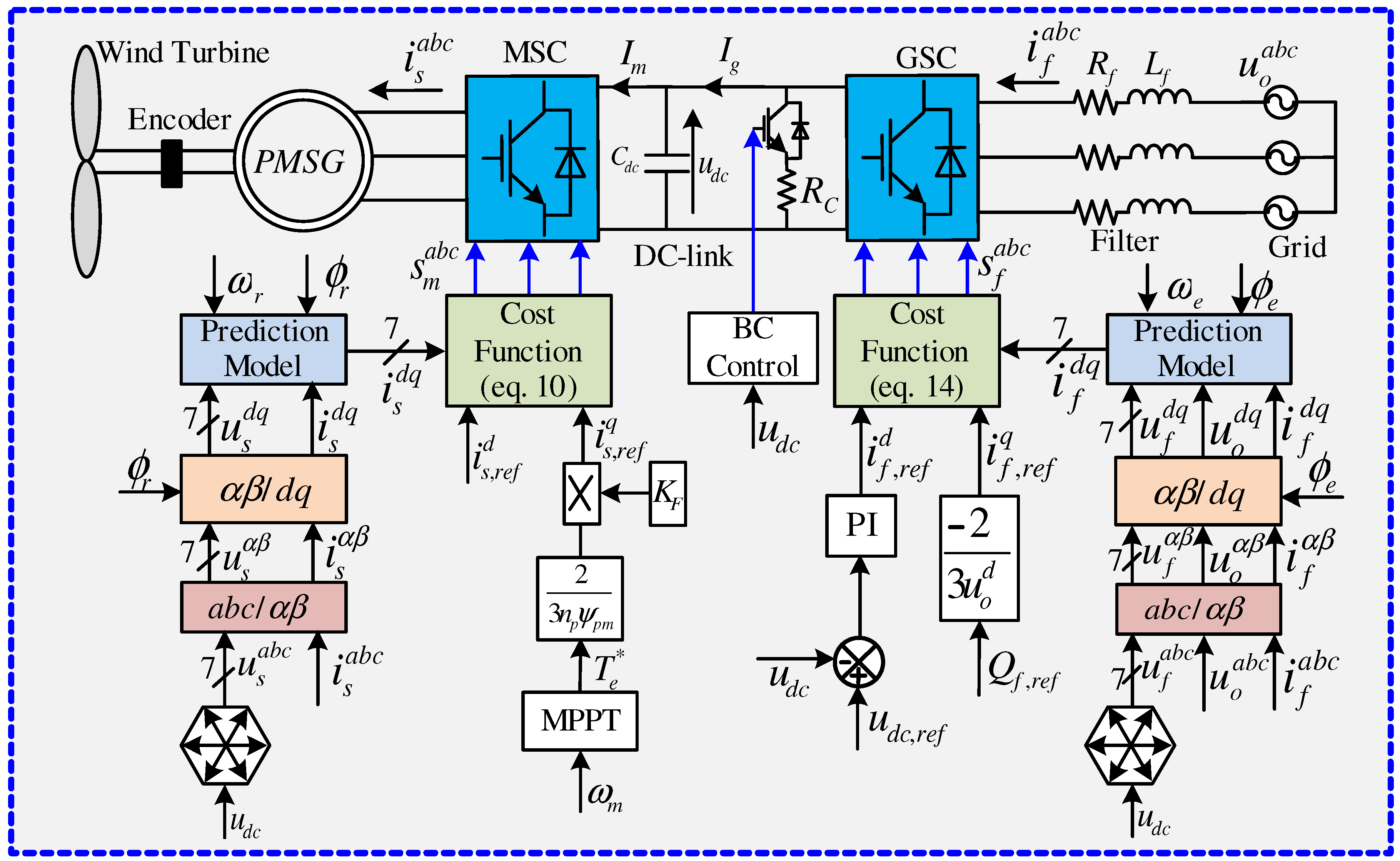
2. Modeling of the WECSs

The block diagram of the PMSG-based wind turbines is illustrated in Figure 1. The PMSG is mechanically connected to the wind turbine directly via a stiff shaft. The stators of the PMSG are tied via a back-to-back full-scale power converter and a filter to the grid.

2.1. Permanent-Magnet Synchronous Generator (PMSG)

The model of the PMSG in the rotating reference frame ( d q ) can be written as follows [30,31]:
u s d = R s i s d + L s d d t i s d ω r L s i s q u s q = R s i s q + L s d d t i s q + ω r L s i s d + ω r ψ p m ,
d d t ω m = 1 Θ T e T m T e = 3 2 n p ψ p m i s q . ,
where u s d , u s q , i s d , i s q are the d- and q-axis components of the stator voltage and current of the PMSG, respectively. R s and L s are the stator resistance and inductance, respectively. ω r = n p ω m is the electrical angular speed of the rotor ( n p is pole pair number and ω m is mechanical angular speed of the rotor) and ψ p m is the permanent-magnet flux. T e is the electro-magnetic machine torque and T m is the mechanical torque produced by the wind turbine. Θ is the rotor inertia of the wind turbine and PMSG.

2.2. Back-to-Back Converter and DC-Link

The output voltage of the MSC u s a b c = ( u s a , u s b , u s c ) and GSC u f a b c = ( u f a , u f b , u f c ) in the a b c reference frame (three-phase system) can be expressed as follows [30,31]:
u s a u s b u s c = 1 3 u d c 2 1 1 1 2 1 1 1 2 s m a s m b s m c ,
u f a u f b u f c = 1 3 u d c 2 1 1 1 2 1 1 1 2 s f a s f b s f c ,
where s m a b c = ( s m a , s m b , s m c ) { 0 , 1 } and s f a b c = ( s f a , s f b , s f c ) { 0 , 1 } are the switching state vectors of the MSC and GSC, respectively. u d c is the DC-link voltage.
Taking into account all the different combinations of the switching state vectors s m a b c or s f a b c : eight switching states, and accordingly, seven voltage vectors are obtained (two different zero voltage vectors are available). The DC-link dynamics can be expressed as
d d t u d c = 1 C d c ( I g I m ) ,
where
I m = ( i s a b c ) s m a b c and I g = ( i f a b c ) s f a b c
are the machine and grid side DC-link currents. i s a b c = ( i s a , i s b , i s c ) and i f a b c = ( i f a , i f b , i f c ) are the PMSG and GSC currents in the a b c reference frame (see Figure 1).

2.3. Filter and Grid

Voltage oriented control of the GSC is realized by aligning the d-axis of the rotating reference frame d q with the grid voltage vector, which rotates with the grid angular frequency ω e (considering ideal conditions, i.e., fixed grid frequency f e > 0 , ω e = 2 π f e is constant). Therefore, the model for the GSC and grid can be expressed as [30,31]:
u o d = R f i f d + L f d d t i f d ω e L f i f q + u f d u o q = R f i f q + L f d d t i f q + ω e L f i f d + u f q ,
where u o d , u o q are the d- and q-axis components of the grid voltage and u f d , u f q , i f d , i f q are the d- and q-axis components of the output voltage and current of the GSC, respectively. R f , L f are the resistance and inductance of the output filter.

3. Direct Model Predictive Control (DMPC)

Recently, the direct model predictive control (DMPC) scheme is considered a simple and promising control scheme for power converters and electric drives [32]. DMPC eliminates the necessity for linear regulators (PI controllers) and modulators. The DMPC is a nonlinear control method and has the advantage of good dynamic performance. The main disadvantage of the DMPC scheme is the higher computational load. However, the modern digital signal processors have a high calculation capacity, which makes the implementation of DMPC feasible. Recently, several works have demonstrated that DMPC schemes can be easily applied to various applications [30,31,32,33,34,35,36,37,38,39,40].

3.1. DMPC for MSC

Figure 1 illustrates the proposed DMPC for MSC. According to the DMPC concept, Equation (1) is solved for d d t i s d and d d t i s q , yielding
d d t i s d = R s L s i s d + ω r i s q + 1 L s u s d d d t i s q = R s L s i s q ω r i s d ω r L s ψ p m + 1 L s u s q . .
A discrete-time model is requested for predicting the future current in the next sampling interval. Therefore, the forward Euler method with sampling time T s is applied to the time-continuous model (8). For small T s 1 , the following holds: i ( k ) : = i ( k T s ) i ( t ) and d d t i ( t ) = i ( k + 1 ) i ( k ) T s for all t [ k T s , ( k + 1 ) T s ] . Consequently, the discrete model of the PMSG can be expressed as [30,31]:
i s d ( k + 1 ) = ( 1 T s R s L s ) i s d ( k ) + ω r T s i s q ( k ) + T s L s u s d ( k ) i s q ( k + 1 ) = ( 1 T s R s L s ) i s q ( k ) ω r T s i s d ( k ) ω r T s L s ψ p m + T s L s u s q ( k ) .
For the MSC, the cost function is defined by
g M S C = | i s , r e f d ( k + 1 ) i s d ( k + 1 ) | + | i s , r e f q ( k + 1 ) i s q ( k + 1 ) | + 0 if i s d ( k + 1 ) 2 + i s q ( k + 1 ) 2 i s , m a x if i s d ( k + 1 ) 2 + i s q ( k + 1 ) 2 > i s , m a x ,
where i s , r e f d ( k + 1 ) , i s , r e f q ( k + 1 ) are the reference values of the d- and q-axis currents. k is the current sampling instant and i s , m a x is the maximum allowable output current of the MSC. The cost function (10) is selected to minimize the tracking error between the reference value i s , r e f d q ( k + 1 ) and actual value i s d q ( k + 1 ) of the stator current (as we do a current control in this work). The future reference current i s , r e f k ( k + 1 ) is calculated using Lagrange extrapolation as [35]:
i s , r e f d / q ( k + 1 ) = 3 i s , r e f d / q ( k ) 3 i s , r e f d / q ( k 1 ) + i s , r e f d / q ( k 2 ) .
The value of the d-axis reference current i s , r e f d ( k ) is always set to be zero and the value of the q-axis reference current i s , r e f q ( k ) is calculated based on the optimal torque T e as i s , r e f q ( k ) = 2 3 T e ( K ) n p ψ p m . The optimal torque T e is computed from the MPPT algorithm [30].
According to the DMPC concept, Equation (9) is computed for the seven possible voltage vectors. Consequently, seven predicted currents are produced. Then, the cost function (10) is evaluated for the seven predicted currents and the voltage vector whose current prediction is optimizing the cost function will be applied in the next sampling instant.

3.2. DMPC for GSC

The proposed DMPC for the GSC is shown in Figure 1. Solving Equation (7) for d d t i f d and d d t i f q yields
d d t i f d = R f L f i f d + ω e i f q + 1 L f ( u o d u f d ) d d t i f q = R f L f i f q ω e i f d + 1 L f ( u o q u f q ) .
According to the forward Euler method principles, the discrete time model of the output filter and grid can be written as [30,31]:
i f d ( k + 1 ) = ( 1 T s R f L f ) i f d ( k ) + ω e T s i f q ( k ) + T s L f ( u o d ( k ) u f d ( k ) ) i f q ( k + 1 ) = ( 1 T s R f L f ) i f q ( k ) ω e T s i f d ( k ) + T s L f ( u o q ( k ) u f q ( k ) ) .
For the GSC, the cost function is defined by
g G S C = | i f , r e f d ( k + 1 ) i f d ( k + 1 ) | + | i f , r e f q ( k + 1 ) i f q ( k + 1 ) | + 0 if i f d ( k + 1 ) 2 + i f q ( k + 1 ) 2 i f , m a x if i f d ( k + 1 ) 2 + i f q ( k + 1 ) 2 > i f , m a x ,
where i f , r e f d ( k + 1 ) , i f , r e f q ( k + 1 ) are the reference values of the d- and q-axis currents, and i f , m a x is the maximum allowable output current of the GSC. The future reference current i f , r e f k ( k + 1 ) is calculated using Lagrange extrapolation as explained above.
The value of the d-axis reference current i f , r e f d is obtained from an outer DC-link voltage control loop [30,31]. The measured DC-link voltage u d c is compared with a constant reference value u d c , r e f and the error is processed by a PI controller producing the d-axis reference current i f , r e f d (see Figure 1). The value of the q-axis reference current i f , r e f q is calculated based on the required reference reactive power as i f , r e f q = 2 3 Q f , r e f u o d .
Again, following the same procedure of the DMPC explained above, the optimal voltage vector to be applied in the next sampling period will be selected.

4. Proposed FRT Strategy

During faults or voltage dips in the grid side, the grid voltage u o = ( u o d ) 2 + ( u o q ) 2 will be lower than the rated value 1 [pu]. Therefore, the delivered active power to the grid will be reduced [39]. However, without FRT control strategy, the PMSG will continue supplying active power to the DC-link. Consequently, the difference between the generated power from the PMSG and the delivered power to the grid will be accumulated in the DC-link capacitor. Accordingly, the DC-link voltage u d c increases to a value that can cause damage to the DC-link capacitor. The traditional solution for this problem is utilizing a BC in the DC-link [39]. When the DC-link voltage reaches the threshold value (i.e., 1.1 u d c ), the BC will turn on. Consequently, the surplus power dissipates in the BC resistance R c , as shown in Figure 1. However, the BC solution can only dissipate the surplus power and cannot deliver reactive power to the grid. Accordingly, this solution failed in achieving the new grid code requirements.
The proposed FRT strategy is illustrated in Figure 1. The q-axis reference current i s , r e f q of the PMSG is multiplied by a factor K F , which can be expressed as
K F = 1 if u o 0.9 [ pu ] u o u o , r a t e d if u o < 0.9 [ pu ] ,
where u o , r a t e d = 1 pu is the rated value of the grid voltage and u o is the magnitude of the grid voltage during the fault/voltage dip. Therefore, during the normal operation conditions u o 0.9 , the DMPC of the MSC will track the maximum power point of the wind turbine (i.e., K F = 1). During faults/voltage dips in the grid side, the generated power from the PMSG will be decreased according to the depth of the voltage dip/fault (i.e., K F < 1 ). Consequently, the surplus active power will be stored in the inertia of the rotor of the WECS [39]. Thus, the mechanical speed of the shaft increases. After fault clearness, this stored active power will be injected back to the grid.
In order to fulfill the new grid code requirements, the maximum allowable reactive current will be injected to the grid during the fault, which can be expressed as
i f , r e f q = ( i f , m a x ) 2 ( i f , r e f d ) 2 .

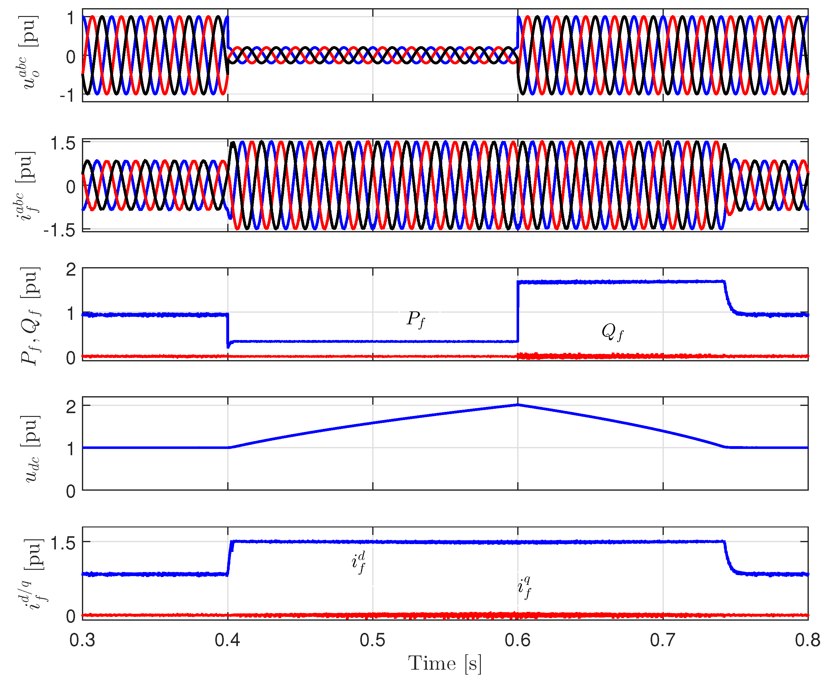
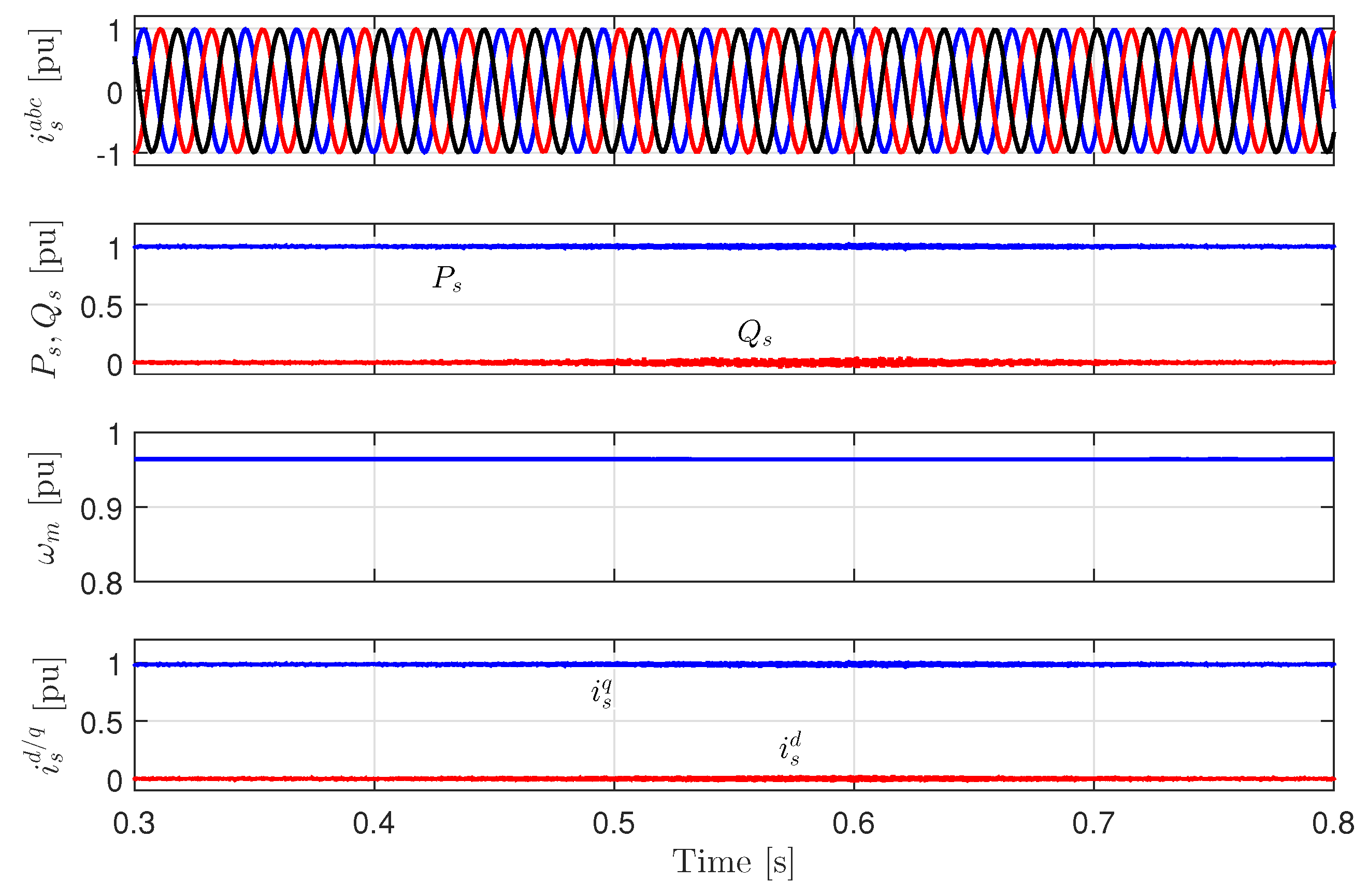
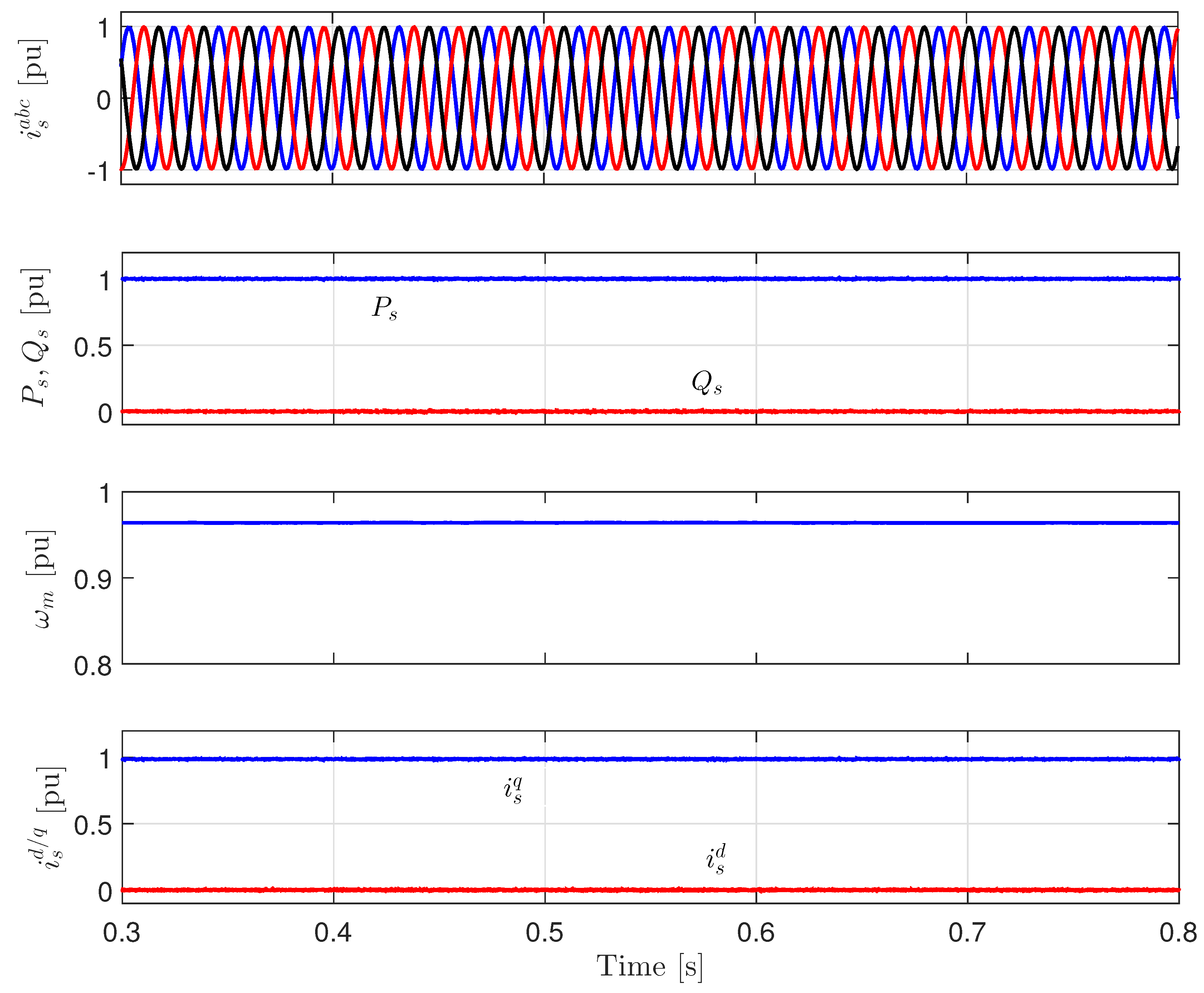
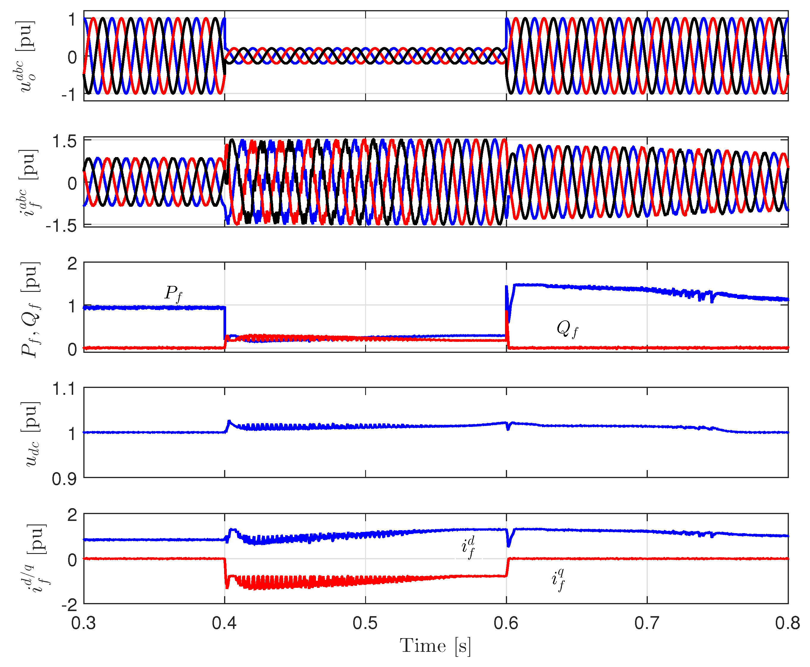
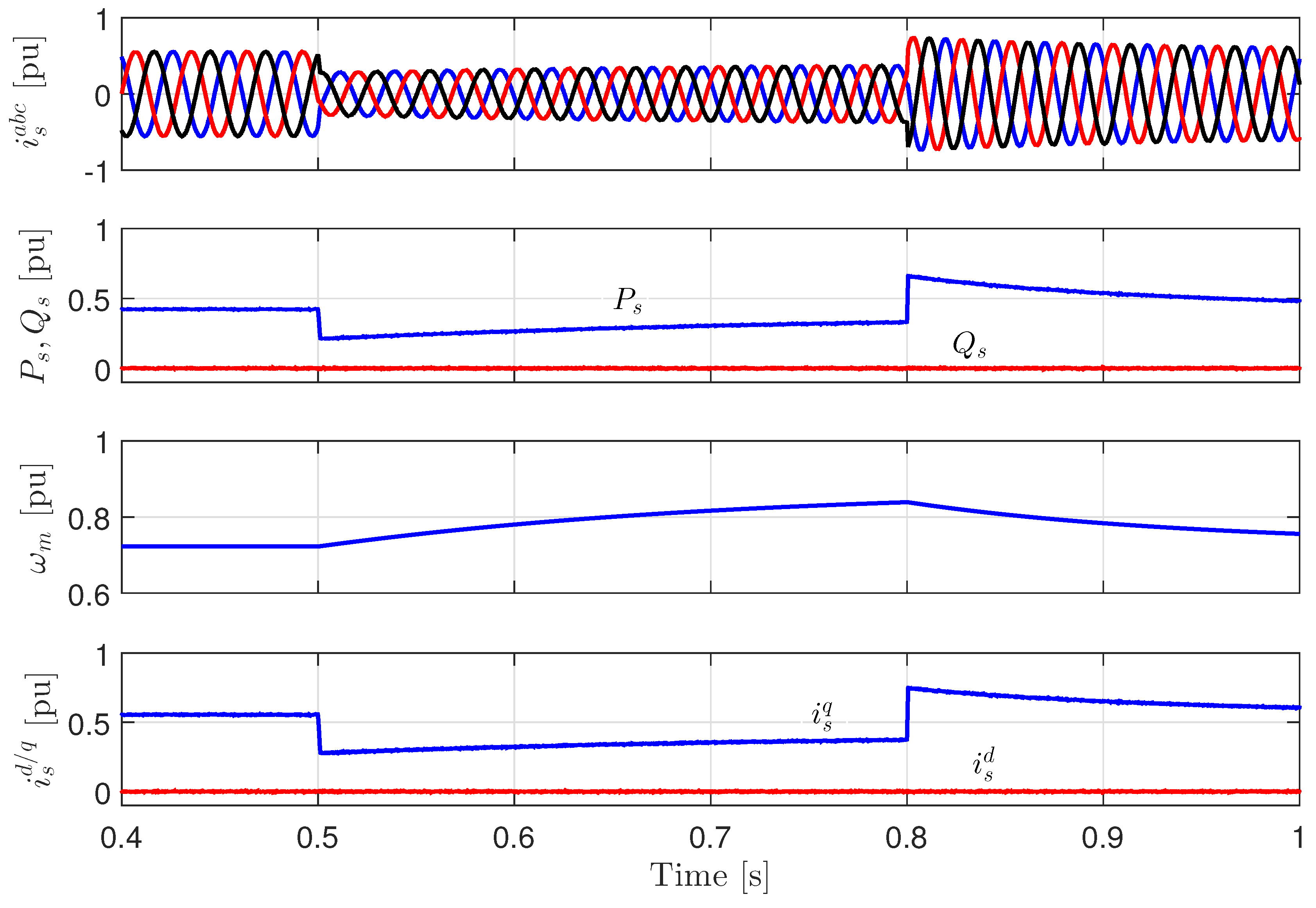
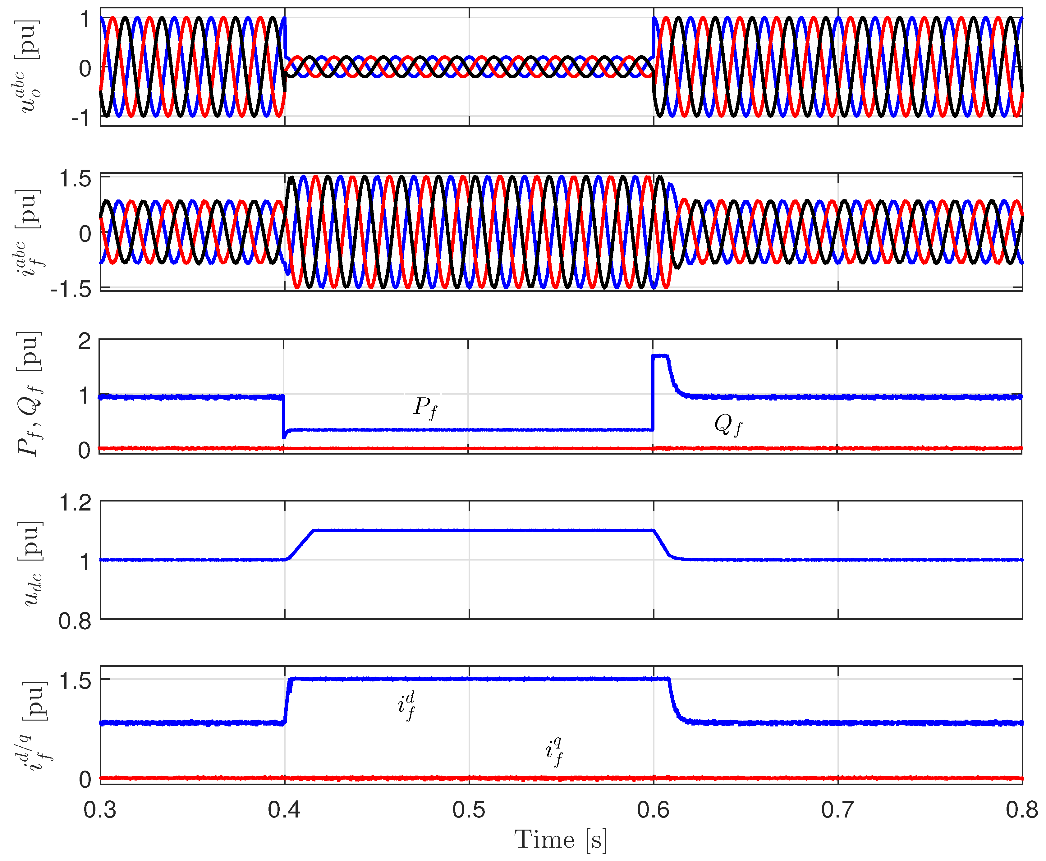
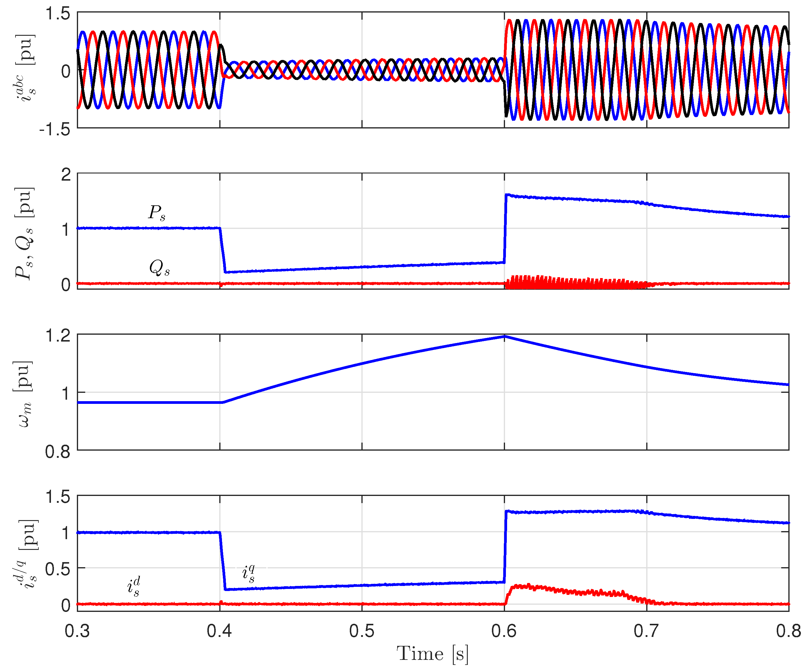
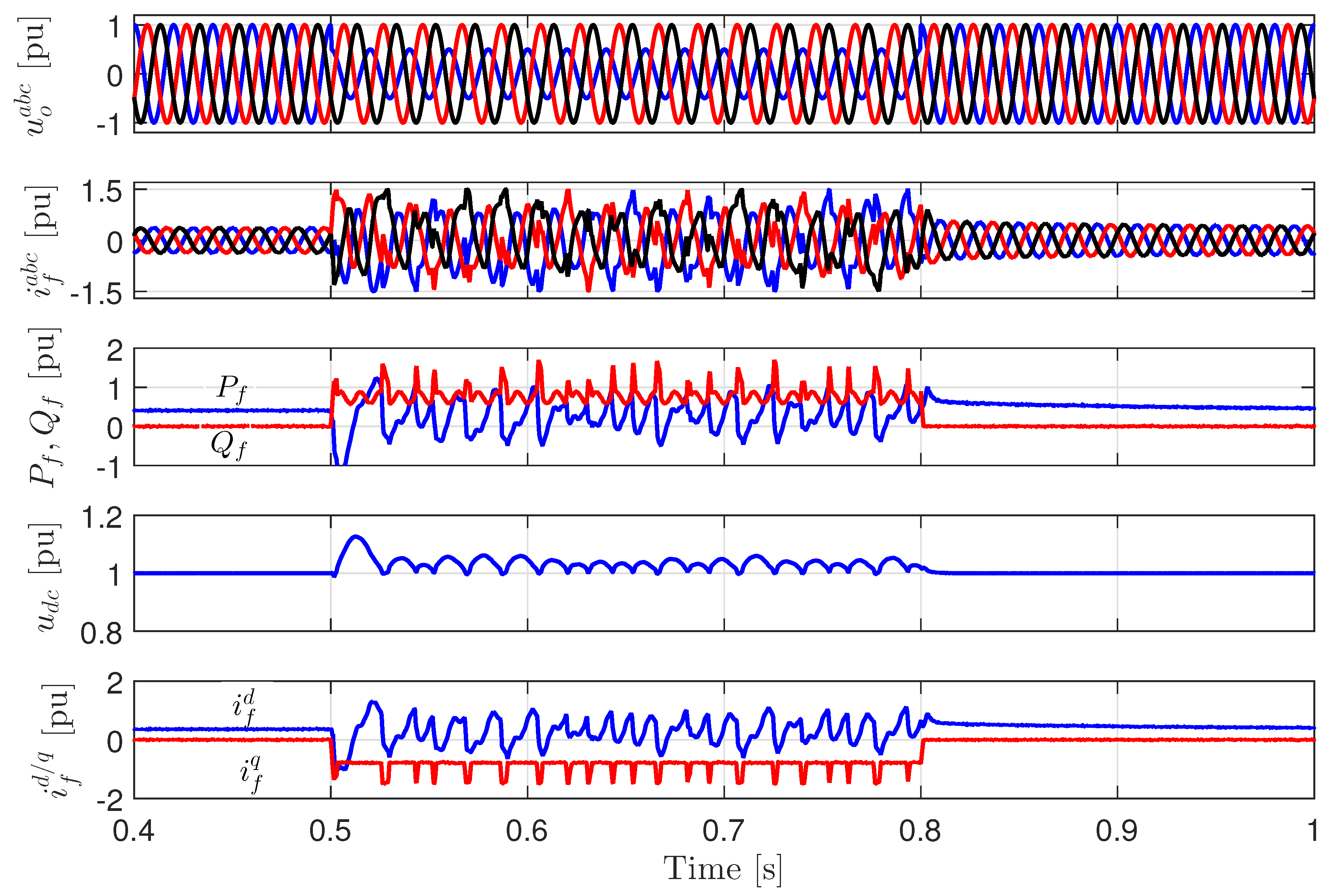
5. Simulation Results

A 20 kW WECS with PMSG is implemented in Matlab/Simulink (2015a, MathWorks, Natick, MA, USA). The system parameters are given in Table 1, and the implementation is shown in Figure 1. For implementing the proposed DMPC, the sampling time was selected to be 40 μs, which yields acceptable current/torque ripples and a maximum switching frequency of 1/(2 × 40 × 10−6) = 12.5 kHz. If the sampling time is chosen lower than 40 μs, the current/torque ripple will be reduced. However, the switching frequency, and, consequently, the switching losses will be increased as well. Fixed-step solvers solve the system model at simulation steps from the start to the end of the simulation. In general, reducing the simulation step increases the accuracy of the results and increases the time required to simulate the system. Accordingly, the simulation step was selected to be 1 μs.
The results are given in a per unit (pu) system. The base values for the WECS are listed in Table 1. The transformation from the actual value to pu value can be expressed as
pu value = Actual value Base value .
Figure 2 shows the performance of the GSC and DC-link during a three-phase fault in the grid side without FRT strategy at the rated wind speed 20 m/s. At the time instant t = 0.4 s, an 85% voltage dip in the grid voltage occurred for a period 200 [ms]. As explained in Section 4, during the faults/voltage dips, the active power P f injected to the grid decreases (see Figure 2) while the generated active power P s from the PMSG is constant (see Figure 3). Therefore, the output currents of the GSC i f a b c increase in order to regulate the DC-link voltage. However, the output currents reach the maximum allowable value 1.5 pu, as shown in Figure 2. Accordingly, the surplus active power accumulates in the DC-link capacitor causing an increase of the DC-link voltage u d c to a very high value 2 pu. This voltage is enough to destroy the DC-link capacitor. After the fault clearance at the instant t = 0.6 s, the DC-link voltage recovers by injecting more active power to the grid than that generated. Consequently, the d-axis current i f d of the GSC is still constant at the maximum allowable value even after the fault clearance.
Figure 3 illustrates the performance of the MSC and PMSG during the same three-phase fault as in Figure 2 without FRT strategy. There are no changes in the PMSG currents, generated active and reactive power, and mechanical speed of the rotor due to the full decoupling between the grid and the generator.
In order to protect the DC-link capacitor, the traditional solution is connecting a braking chopper parallel with the DC-link capacitor. In order to investigate the effectiveness of this BC solution, the simulation is re-performed under the same wind speed (i.e., 20 m/s) and the same three-phase fault as in Figure 2. Figure 4 illustrates the performance of the GSC and grid with the BC-FRT solution. After the fault occurrences, the DC-link voltage increases. However, when the DC-link voltage reaches the threshold value (i.e., u d c = 1.1 pu), the BC is activated and the surplus active power dissipates in the BC resistance. Accordingly, the DC-link voltage is kept constant at the threshold value. According to Figure 4, the BC solution has the capability to protect the DC-link capacitor. However, according to the new grid code requirements, the WECS must inject reactive power to the grid during the faults/voltage dips. This requirements can not be achieved using the BC solution.
Figure 5 shows the performance of the MSC and PMSG during the same three-phase fault as in Figure 2 with the BC-FRT strategy. Again, there are no changes in the generator currents, active and reactive power, and mechanical speed of the rotor, thanks to the full decoupling between the grid and the generator.
The performance of the GSC and DC-link during the same three-phase fault with the proposed FRT strategy is illustrated in Figure 6. According to Equation (15), when the fault/voltage dip is detected, the q-axis reference current i s , r e f q of the PMSG is multiplied by the factor K F . Accordingly, the generated active power P s from the PMSG decreases as shown in Figure 7. Therefore, a mismatch between the output mechanical power from the wind turbine and generated power from the PMSG is produced. As a consequence, the rotor mechanical speed ω m of the PMSG increases and the surplus power will be stored in the inertia of the rotor of the WECS (see Figure 7). Therefore, the DC-link voltage is kept almost constant at its reference value 1 pu. Moreover, during the fault, a reactive power Q f is injected to the grid. The q-axis reference current i f , r e f q of the GSC is calculated according to (16). Thus, more than 1 pu reactive current is injected into the grid. Accordingly, the proposed FRT strategy succeeded in protecting the DC-link capacitor and achieving the grid code requirements without any extra hardware components.
After the fault clearance, the stored energy in the rotating mechanical system of the WECS is injected back into the grid via the DC-link. The injected power after the fault is equal to the sum of the output mechanical power from the wind turbine and the stored power during the fault. Therefore, the q-axis current of the PMSG i s q and the d-axis current of the GSC i f d reach the limit 1.5 pu. Consequently, the speed of the rotor of the PMSG decreases and reaches the pre-fault value after delivering all the stored power to the grid.
Comparing the performance of the proposed FRT strategy (Figure 6 and Figure 7) with the performance of BC solution (Figure 4 and Figure 5) shows that the proposed FRT strategy gives superior performance. The main drawback of the proposed FRT strategy is the stress in the mechanical components of the wind turbine and PMSG during the fault. However, as shown in Figure 7, the mechanical speed of the PMSG is still within the safe limit 1.2 pu, although the wind turbine operates at the rated wind speed 20 m/s.
In order to investigate the performance of the proposed FRT strategy during unbalanced faults, a single phase to ground fault has been applied in the grid side. At the time instant t = 0.5 s, a 50% voltage dip in phase a of the grid is applied for a period of 300 ms. The simulation is re-performed under a wind speed 15 m/s. Figure 8 shows the performance of the GSC and DC-link under the single phase to ground fault with the proposed FRT strategy. Again, the proposed FRT strategy succeeded in protecting the DC-link capacitor. The DC-link voltage is almost constant at 1 pu. Moreover, approximately 1 pu reactive power/current is injected into the grid. Thus, the proposed FRT fulfills the new grid code requirements.
The performance of the MSC and PMSG under the single phase to ground fault is illustrated in Figure 9. As explained above, during the fault, the generated active power from the PMSG reduces and the surplus active power is stored in the inertia of the WECS. Therefore, the mechanical speed of the PMSG increases. However, the mechanical speed did not reach the rated value 1 pu. Accordingly, there is no stress on the mechanical components of the wind turbine and PMSG in this case.

6. Conclusions

In this paper, an FRT strategy for PMSG-based variable-speed wind turbines is proposed. The proposed FRT strategy uses the rotor inertia of a WECS (inertia of the wind turbine and PMSG) to store the surplus power during faults/voltage dips in the grid side.The performance of the proposed FRT strategy has been verified and compared with the traditional BC solution by simulation results under symmetrical and asymmetrical faults/voltage dips. The results illustrated that the proposed FRT strategy guarantees keeping the DC-link voltage almost constant at its reference value (i.e., 1 pu) and injecting active and reactive power into the grid during faults/voltage dips. Furthermore, the proposed FRT strategy gives superior performance in comparison with the traditional BC solution. Accordingly, the proposed FRT strategy fulfills the new grid code requirements without any additional hardware components.

Acknowledgments

This work was supported by the German Research Foundation (DFG) and the Technical University of Munich (TUM) in the framework of the Open Access Publishing Program.

Author Contributions

Mohamed Abdelrahem conceived, designed, implemented the proposed control strategy, and wrote the manuscript. Ralph Kennel was responsible for the guidance and a number of key suggestions.

Conflicts of Interest

The authors declare no conflict of interest.

References

  1. Liserre, M.; Cardenas, R.; Molinas, M.; Rodriguez, J. Overview of Multi-MW Wind Turbines and Wind Parks. IEEE Trans. Ind. Electron. 2011, 58, 1081–1095. [Google Scholar] [CrossRef]
  2. Li, H.; Chen, Z. Overview of different wind generator systems and their comparisons. IET Renew. Power Gener. 2008, 2, 123–138. [Google Scholar] [CrossRef]
  3. Hansen, A.; Iov, F.; Blaabjerg, F.; Hansen, L. Review of contemporary wind turbine concepts and their market penetration. J. Wind Eng. Ind. Aerodyn. 2004, 28, 247–263. [Google Scholar] [CrossRef]
  4. Global Wind Energy Council (GWEC). Global Wind Report 2015. Available online: http://www.gwec.net/ (accessed on 13 August 2016).
  5. Tsili, M.; Papathanassiou, S. A review of grid code technical requirements for wind farms. IET Renew. Power Gener. 2009, 3, 308–332. [Google Scholar] [CrossRef]
  6. Cardenas, R.; Pena, R.; Alepuz, S.; Asher, G. Overview of Control Systems for the Operation of DFIGs in Wind Energy Applications. IEEE Trans. Ind. Electron. 2013, 60, 2776–2798. [Google Scholar] [CrossRef]
  7. Abdelrahem, M.; Hackl, C.; Kennel, R. Application of Extended Kalman Filter to Parameter Estimation of Doubly-Fed Induction Generators in Variable-Speed Wind Turbine Systems. In Proceedings of the 5th International Conference on Clean Electrical Power (ICCEP), Taormina, Italy, 16–18 June 2015.
  8. Abdelrahem, M.; Hackl, C.; Kennel, R. Sensorless Control of Doubly-Fed Induction Generators in Variable-Speed Wind Turbine Systems. In Proceedings of the 5th International Conference on Clean Electrical Power (ICCEP), Taormina, Italy, 16–18 June 2015.
  9. Chinchilla, M.; Arnaltes, S.; Burgos, J. Control of permanent magnet generators applied to variable-speed wind-energy systems connected to the grid. IEEE Trans. Energy Convers. 2006, 21, 130–135. [Google Scholar] [CrossRef]
  10. Abdelrahem, M.; Hackl, C.; Zhang, Z.; Kennel, R. Sensorless Control of Permanent Magnet Synchronous Generators in Variable-Speed Wind Turbine Systems. In Proceedings of the Power and Energy Student Summit (PESS 2016), Aachen, Germany, 19–20 January 2016.
  11. Nasiri, M.; Milimonfared, J.; Fathi, S.H. A review of low-voltage ride-through enhancement methods for permanent magnet synchronous generator based wind turbines. Renew. Sustain. Energy Rev. 2015, 47, 399–415. [Google Scholar] [CrossRef]
  12. Conroy, J.; Watson, R. Low-voltage ride-through of a full converter wind turbine with permanent magnet generator. IET Renew. Power Gener. 2007, 1, 182–189. [Google Scholar] [CrossRef]
  13. Mendes, V.F.; Matos, F.F.; Liu, S.Y.; Cupertino, A.F.; Pereira, H.A.; de Sousa, C.V. Low Voltage Ride-Through Capability Solutions for Permanent Magnet Synchronous Wind Generators. Energies 2016, 9, 59. [Google Scholar] [CrossRef]
  14. Heng, N.; Jiao, L.; Peng, Z.; Yikang, H. Improved control strategy of an active crowbar for directly-driven PM wind generation system under grid voltage dips. In Proceedings of the International Conference on Electrical Machines and Systems (ICEMS), Wuhan, China, 17–20 October 2008.
  15. Nauyen, T.; Lee, D. Ride-through technique for PMSG wind turbines using energy storage systems. J. Power Electron. 2010, 10, 733–738. [Google Scholar] [CrossRef]
  16. Bolund, B.; Bernhoff, H.; Leijon, M. Flywheel energy and power storage systems. Renew. Sustain. Energy Rev. 2007, 11, 235–258. [Google Scholar] [CrossRef]
  17. Xu, G.; Xu, L.; Morrow, D. Wind turbines with energy storage for power smoothing and FRT enhancement. In Proceedings of the IEEE Power and Energy Society General Meeting, San Diego, CA, USA, 24–29 July 2011.
  18. Peng, Y.; Li, Y.; Xu, Z.; Wen, M.; Luo, L.; Cao, Y.; Leonowicz, Z. Power Quality Improvement and LVRT Capability Enhancement of Wind Farms by Means of an Inductive Filtering Method. Energies 2016, 9, 302. [Google Scholar] [CrossRef]
  19. Mohod, S.W.; Aware, M.V. A STATCOM-control scheme for grid connected wind energy system for power quality improvement. IEEE Syst. J. 2010, 4, 346–352. [Google Scholar] [CrossRef]
  20. Wang, L.; Truong, D.N. Dynamic stability improvement of four parallel-operated PMSG-based offshore wind turbine generators fed to a power system using a STATCOM. IEEE Trans. Power Deliv. 2013, 28, 111–119. [Google Scholar] [CrossRef]
  21. Goweily, K.; El Moursi, M.; Abdel-Rahman, M.; Badr, M.A.L. Voltage booster scheme for enhancing the fault ride-through of wind turbines. IET Power Electron. 2015, 8, 1853–1863. [Google Scholar] [CrossRef]
  22. Causebrook, A.; Atkinson, D.J.; Jack, A.G. Fault ride-through of large wind farms using series dynamic braking resistors. IEEE Trans. Power Syst. 2007, 22, 966–975. [Google Scholar] [CrossRef]
  23. Tongzhou, J.; Xiongfeng, H.; Xianyun, L.; Kun, L.; Mei, Z. Performance analysis and research on LVRT of PMSG wind power system with SDBR. In Proceedings of the 33rd Chinese Control Conference, Nanjing, China, 28–30 July 2014.
  24. Wu, Z.; Dou, X.; Chu, J.; Hu, M. Operation and Control of a Direct-Driven PMSG-Based Wind Turbine System with an Auxiliary Parallel Grid-Side Converter. Energies 2013, 6, 3405–3421. [Google Scholar]
  25. Huang, H.; Mao, C.; Lu, J.; Wang, D. Electronic Power Transformer Control Strategy in Wind Energy Conversion Systems for Low Voltage Ride-through Capability Enhancement of Directly Driven Wind Turbines with Permanent Magnet Synchronous Generators (D-PMSGs). Energies 2014, 7, 7330–7347. [Google Scholar] [CrossRef]
  26. Liu, Z.; Liu, C.; Li, G. Power coordinated control of wind turbines with permanent magnet synchronous generator for low voltage ride through. In Proceedings of the IEEE Power & Energy Society General Meeting, National Harbor, MD, USA, 27–31 July 2014.
  27. Hansen, A.D.; Michalke, G. Modelling and control of variable-speed multi-pole permanent magnet synchronous generator wind turbine. Wind Energy 2008, 11, 537–554. [Google Scholar] [CrossRef]
  28. Alepuz, S.; Calle, A.; Busquets-Monge, S.; Kouro, S.; Wu, B. Use of Stored Energy in PMSG Rotor Inertia for Low-Voltage Ride-Through in Back-to-Back NPC Converter-Based Wind Power Systems. IEEE Trans. Ind. Electron. 2013, 60, 1787–1796. [Google Scholar] [CrossRef]
  29. Yaramasu, V.; Wu, B.; Alepuz, S.; Kouro, S. Predictive Control for Low-Voltage Ride-Through Enhancement of Three-Level-Boost and NPC-Converter-Based PMSG Wind Turbine. IEEE Trans. Ind. Electron. 2014, 61, 6832–6843. [Google Scholar] [CrossRef]
  30. Abdelrahem, M.; Hackl, C.; Kennel, R. Model Predictive Control of Permanent Magnet Synchronous Generators in Variable-Speed Wind Turbine Systems. In Proceedings of the Power and Energy Student Summit (PESS 2016), Aachen, Germany, 19–20 January 2016.
  31. Mobarak, M.; Abdelrahem, M.; Stati, N.; Kennel, R. Model Predictive Control for Low-Voltage Ride-Through Capability Improvement of Variable-Speed Wind Energy Conversion Systems. In Proceedings of the IEEE International Symposium on Industrial Electronics (INDEL), Banja Luka, Bosnia and Herzegovina, 3–5 November 2016.
  32. Cortes, P.; Kazmierkowski, M.; Kennel, R.; Quevedo, D.; Rodriguez, J. Predictive Control in Power Electronics and Drives. IEEE Trans. Ind. Electron. 2008, 55, 4312–4324. [Google Scholar] [CrossRef]
  33. Linder, A.; Kanchan, R.; Kennel, R.; Stolze, P. Model-Based Predictive Control of Electric Drives; Cuvillier Verlag: Göttingen, Germany, 2010. [Google Scholar]
  34. Kouro, S.; Cortes, P.; Vargas, R.; Ammann, U.; Rodriguez, J. Model Predictive Control—A Simple and Powerful Method to Control Power Converters. IEEE Trans. Ind. Electron. 2009, 56, 1826–1838. [Google Scholar] [CrossRef]
  35. Rodriguez, J.; Cortes, P. Predictive Control of Power Converters and Electrical Drives, 1st ed.; Wiley-IEEE Press: New York, NY, USA, 2012. [Google Scholar]
  36. Zhang, Z.; Hackl, C.; Abdelrahem, M.; Kennel, R. Voltage Sensorless Direct Model Predictive Control of 3L-NPC Back-to-Back Power Converter PMSG Wind Turbine Systems with Fast Dynamics. In Proceedings of the Power and Energy Student Summit (PESS 2016), Aachen, Germany, 19–20 January 2016.
  37. Nguyen, T.-T.; Yoo, H.-J.; Kim, H.-M. Application of Model Predictive Control to BESS for Microgrid Control. Energies 2015, 8, 8798–8813. [Google Scholar] [CrossRef]
  38. Abdelrahem, M.; Hackl, C.; Kennel, R. Encoderless Model Predictive Control of Doubly-Fed Induction Generators in Variable-Speed Wind Turbine Systems. In Proceedings of the Science of Making Torque from Wind (TORQUE 2016) Conference, Munich, Germany, 5–7 October 2016.
  39. Abdelrahem, M.; Mobarak, M.; Kennel, R. Realization of Low-Voltage Ride Through Requirements for PMSGs in Wind Turbines Systems Using Generator-Rotor Inertia. In Proceedings of the IEEE 9th International Conference on Electrical and Computer Engineering (ICECE), Dhaka, Bangladesh, 20–22 December 2016.
  40. Abdelrahem, M.; Hackl, C.; Kennel, R. Simplified Model Predictive Current Control without Mechanical Sensors for Variable-Speed Wind Energy Conversion Systems. Electr. Eng. J. 2016. [Google Scholar] [CrossRef]
Figure 1. Proposed fault-ride through strategy for permanent-magnet synchronous generator-based wind turbines.
Energies 09 01066 g001
Figure 2. Performance of the GSC and DC-link during a three-phase fault without FRT strategy (from top): grid voltages u o a b c = ( u o a , u o b , u o c ) , GSC output currents i f a b c = ( i f a , i f b , i f c ) , active and reactive power injected to the grid ( P f , Q f ), DC-link voltage u d c , and d- and q-axis currents of the GSC ( i f d , i f q ).
Energies 09 01066 g002
Figure 3. Performance of the MSC and PMSG during a three-phase fault without FRT strategy (from top): PMSG output currents i s a b c = ( i s a , i s b , i s c ) , PMSG active and reactive power ( P s , Q s ), mechanical speed of the PMSG rotor ω m , and d- and q-axis currents of PMSG ( i s d , i s q ).
Energies 09 01066 g003
Figure 4. Performance of the GSC and DC-link during a three-phase fault with BC-FRT strategy (from top): grid voltages u o a b c = ( u o a , u o b , u o c ) , GSC output currents i f a b c = ( i f a , i f b , i f c ) , active and reactive power injected to the grid ( P f , Q f ), DC-link voltage u d c , and d- and q-axis currents of the GSC ( i f d , i f q ).
Energies 09 01066 g004
Figure 5. Performance of the MSC and PMSG during a three-phase fault with BC-FRT strategy (from top): PMSG output currents i s a b c = ( i s a , i s b , i s c ) , PMSG active and reactive power ( P s , Q s ), mechanical speed of the PMSG rotor ω m , and d- and q-axis currents of PMSG ( i s d , i s q ).
Energies 09 01066 g005
Figure 6. Performance of the GSC and DC-link during a three-phase fault with the proposed FRT strategy (from top): grid voltages u o a b c = ( u o a , u o b , u o c ) , GSC output currents i f a b c = ( i f a , i f b , i f c ) , active and reactive power injected to the grid ( P f , Q f ), DC-link voltage u d c , and d- and q-axis currents of the GSC ( i f d , i f q ).
Energies 09 01066 g006
Figure 7. Performance of the MSC and PMSG during a three-phase fault with the proposed FRT strategy (from top): PMSG output currents i s a b c = ( i s a , i s b , i s c ) , PMSG active and reactive power ( P s , Q s ), mechanical speed of the PMSG rotor ω m , and d- and q-axis currents of PMSG ( i s d , i s q ).
Energies 09 01066 g007
Figure 8. Performance of the GSC and DC-link during a single phase to ground fault with the proposed FRT strategy (from top): grid voltages u o a b c = ( u o a , u o b , u o c ) , GSC output currents i f a b c = ( i f a , i f b , i f c ) , active and reactive power injected to the grid ( P f , Q f ), DC-link voltage u d c , and d- and q-axis currents of the GSC ( i f d , i f q ).
Energies 09 01066 g008
Figure 9. Performance of the MSC and PMSG during a single phase to ground fault with the proposed FRT strategy (from top): PMSG output currents i s a b c = ( i s a , i s b , i s c ) , PMSG active and reactive power ( P s , Q s ), mechanical speed of the PMSG rotor ω m , and d- and q-axis currents of PMSG ( i s d , i s q ).
Energies 09 01066 g009
Table 1. Parameters of PMSG-based WECS.
NameNomenclatureValue
Wind turbine radius r t 1.65 m
Rated wind speed v w r a t e d 20 m/s
PMSG rated power P r a t e d 20 kW
PMSG rated voltage (line–line) u s r m s 400 V
Number of pair poles n p 3
Stator resistance R s 0.2 Ω
Stator inductance L s 15 mH
Permanent magnet flux ψ p m 0.85 Vs
PMSG moment of inertiaΘ0.9 kg m 2
DC capacitor C d c 3 mF
DC-link voltage u d c 700 V
Grid line–line voltage u o 400 V
Grid normal frequency f e 50 Hz
Filter resistance R f 0.16 Ω
Filter inductance L f 12 mH
Sampling time T s 40 μs
Simulation step T s i m 1 μs
Base active power P b a s e 20 kW
Base reactive power Q b a s e 20 kvar
Base current of the PMSG (peak) i s , b a s e 54 A
Base mechanical speed ω m , b a s e 102 rad/s
Base DC-link voltage u d c , b a s e 700 V
Base line–line voltage of the grid u o , b a s e 400 V
Base current of the GSC (peak) i f , b a s e 46 A

