Article

Comparison of Optimized Control Strategies of a High-Speed Traction Machine with Five Phases and Bi-Harmonic Electromotive Force

1
University Lille, Centrale Lille, Arts et Metiers ParisTech, HEI, EA 2697-L2EP -Laboratoire d’Electrotechnique et d’Electronique de Puissance, F-59000 Lille, France
2
Key Laboratory of Power System Intelligent Dispatch and Control, Shandong University, Ministry of Education, Jinan 250061, China
3
Naval Academy Research Institute, Ecole Navale/Groupe des Ecoles du Poulmic - CC 600, 29240 Brest, France
*
Author to whom correspondence should be addressed.
Energies 2016, 9(12), 952; https://doi.org/10.3390/en9120952
Submission received: 27 May 2016 / Revised: 25 October 2016 / Accepted: 1 November 2016 / Published: 25 November 2016
(This article belongs to the Collection Electric and Hybrid Vehicles Collection)

Abstract

:
The purpose of the paper is to present the potentialities in terms of the control of a new kind of PM synchronous machine. With five phases and electromotive forces whose first ( E 1 ) and third ( E 3 ) harmonics are of similar amplitude, the studied machine, so-called bi-harmonic, has properties that are interesting for traction machine payload. With three-phase machines, supplied by a mono-harmonic sinusoidal current, the weak number of freedom degrees limits the strategy of control for traction machines especially when voltage saturation occurs at high speeds. As the torque is managed for three-phase machines by a current with only one harmonic, flux weakening is necessary to increase speed when the voltage limitation is reached. The studied five-phase machine, thanks to the increase in the number of freedom degrees for control, aims to alleviate this fact. In this paper, three optimized control strategies are compared in terms of efficiency and associated torque/speed characteristics. These strategies take into account numerous constraints either from the supply (with limited voltage) or from the machine (with limited current densities and maximum acceptable copper, iron and permanent magnet losses). The obtained results prove the wide potentialities of such a kind of five-phase bi-harmonic machine in terms of control under constraints. It is thus shown that the classical Maximum Torque Per Ampere (MTPA) strategy developed for the three-phase machine is clearly not satisfying on the whole range of speed because of the presence of iron losses whose values can no more be neglected at high speeds. Two other strategies have been then proposed to be able to manage the compromises, at high speeds, between the high values of torque and efficiency under the constraints of admissible total losses either in the rotor or in the stator.

1. Introduction

With more than two independent currents, multiphase machines [1] are logically chosen when fault tolerance is required in critical applications, such as historically marine electric propulsion supplied by a current-source inverter and, since the 21st century, in marine [2,3], aerospace [4,5,6,7] and automotive traction [8,9,10,11,12], with multiphase machines supplied by a voltage source inverter. The reason is that, referring to classical wye-coupled three-phase machines, which possess the minimum number of independent currents for achieving a rotating field in normal condition, these machines have more degrees of freedom than the minimum necessary, thus allowing a rotating field even with one opened phase.
In fact, even in normal working conditions with drives without the need for fault-tolerance, it is possible to take advantage of the numerous degrees of freedoms of a multiphase machine, by considering during the design the number of phases as a parameter. For example, more possible winding configurations for low losses, high torque density and smooth torque ripples [13,14,15,16,17,18,19] can be analyzed. Likewise, as the freedom degrees number increases, the vector control gives more possibilities: the study of the current harmonic injection for higher torque density keeping a smooth torque [20,21,22,23,24,25,26]; the enlargement, for traction machines working in flux-weakening mode under voltage saturation [27,28,29,30,31], of the area of working. Finally, multi-leg Voltage Source Inverters (VSI) [32,33] present also numerous PWM(Pulse Width Modulation) control strategies.
The drive considered in the paper concerns a traction machine for an automotive application. During the electromagnetic design, the degrees of freedom associated with a five-phase machine have been taken into consideration by defining an electromotive force that allows establishing new control strategies especially in the speed region where the saturation of voltage occurs.
More precisely, it is known that, with a five-phase permanent magnet (PM) machine that has a third harmonic component in the electromotive force, the efficiency of a maximum torque per ampere strategy can be increased by a third harmonic current injection without deterioration of the torque quality: in [21], for the Surface Permanent Magnet (SPM) machine, a 20% improvement of torque, keeping its quality, can be obtained with the same peak current, important for the sizing of the VSI; in [13,23,24], for SPM machines, 9% to 17% torque improvement always with small ripples has been obtained keeping the same RMS (root mean square) current value, but with different adaptations of the rotor; in [34], a study with a similar IPM rotor as this one of the three-phase Toyota Prius motor, but with a five-phase stator (changing 48 slots to 40 slots), concludes that the same value of torque at low speed can be reached with lower peak current (−13.4%), interesting for the VSI sizing, with a small increase by 2.7% of copper losses.
In the paper, a machine has been designed to have a ratio E 3 / E 1 , higher or equal to one, so that the production of the torque by the third harmonic is not only marginal, but of the same order as the one produced by the first harmonic. The contribution of each harmonic is of the same order, and the choice of repartition between first and third harmonics has to be optimized regarding different objectives and constraints. To the knowledge of the authors, no multiphase machine with such a E 3 / E 1 ratio has been yet considered, except in [19,35,36,37]. In [13,23,24], the ratio E 3 / E 1 in SPM machines was less than 33%, this value being obtained with square wave emf. With the machine here considered, so-called bi-harmonic, it is possible, for a given value of RMS current to produce the same amplitude of torque either with only one harmonic (first or third) or with both harmonics of currents.
This specificity of the machine in terms of degrees of freedom has been used in this paper in order to find different strategies of control under the constraints of maximum peak voltage and losses. Such kinds of studies considering saturation effects have been carried out especially for magnetic saturation in multiphase induction machines and for voltage saturation in multiphase PM synchronous machines. In the case of multiphase induction machines, the improvement of performances is significant, especially during transient operations. In [38,39], for a six-phase induction machine, it is shown that the injection of current harmonics allows increasing by 40% the torque, keeping the same level of peak magnetic saturation in the machine. Of course, as the corresponding current density is increasing, the improvement is only possible during transient operations. Other more recent publications on multiphase induction machines [31,40] confirm the improvement of torque by current injection in transient operation (high current density) especially for more than five phases. It can be concluded that the numerous degrees of freedom offered by a high number of phases give effectively potentialities for improvement of the drive. For a PM synchronous machine, the impacts of the injection of a third harmonic of current and/or voltage have been studied. In [19], for SPM five-phase machines and considering only copper losses, torque-speed characteristics are defined for different values of the ratio of E 3 / E 1 , under the constraints of peak current and the voltage that is imposed by the supply and VSI characteristics. It is shown that important modifications concerning the maximum torque and speed can be expected. In [30], an analytical study on a five-phase PM machine with sinusoidal emf shows that the increase of the torque can also be obtained in flux-weakening operation by injection of a third harmonic current. In this case, the injection of the current harmonic is a way to use the available degrees of freedom of the machine: as in flux-weakening, the peak voltage attains its maximum value, injection of the third harmonic of current actually also allows the first harmonic of current to increase while keeping the same maximum value of voltage. In [22], for the same five-phase machine as in [30], optimization is achieved in the flux-weakening area taking into account also iron and permanent magnet losses: previous results concerning the benefit of third harmonic injection even in the case of sinusoidal five-phase PM machines are confirmed. The work in [37] focuses on a particular bi-harmonic SPM machine with a ratio of E 3 / E 1 = 100% and with the same number of slots and poles as this one proposed in the paper. The necessity to consider not only copper, but also iron and magnet losses for the definition of the control strategy is demonstrated: if at low speed, supply by only the third harmonic leads to good performance, the losses in the permanent magnet are becoming too important at high speeds, and different repartitions between the harmonic of current must be considered.
This paper will be organized as follows. After the description and characterization of the special machine in Section 2, a maximum torque per ampere strategy taking into account voltage limitation is described in Section 3. An optimal ratio between the first and third harmonic of currents is found in order to minimize the copper losses, for a given torque and imposed current density of 10 A/mm 2 . Calculations of magnet and iron losses show that they are not negligible (more than 20% of total losses) upon 2000 rpm. In Section 4, two Maximum Torque per Loss Strategies (MTPL(I) and MTPL(II)), with different constraints on rotor and stator losses, are consequently introduced, and the corresponding four-dimensional current vectors are calculated at low speeds and at high speeds (Section 4.2). For these strategies, iron and magnet losses developed in a machine supplied simultaneously by two harmonics of currents must be calculated and injected in the optimization process. Moreover, magnetic saturation effects were observed when supplied by two harmonic with a current density of 10 A/mm 2 . It was thus necessary to adopt modeling based on the Finite Element Method (FEM) instead of an analytical approach. In order to be able to achieve the optimization process in an acceptable time duration, a surrogate-assisted algorithm [41], called Efficient Global Optimization (EGO) [42], has been used. This method is briefly described in Section 4.3. Final results are presented in Section 4.4 and show important differences between the Maximum Torque Per Ampere (MTPA) and MTPL strategies upon the speed of 2000 rpm. At higher speeds, it is shown that, thanks to its four independent currents, adequate control can allow the machine to work under various constraints.

2. Presentation and Characterization of the Five-Phase Machine

We present below the context of the design of a five-phase machine for a hybrid automotive application. First of all, for a mass market product, the facilities of making, recycling and repairing are of importance: as the winding is one of the most complex parts of the process in a classical machine, concentrated tooth windings with simple and short end-windings have been chosen. Four qualitative constraints are also considered with the corresponding qualitative choices made for the presented machine:
  • For hybrid vehicles, the required volume density is high: permanent magnet machines are then preferred [43,44]; moreover, the use of high speeds allows obtaining, for a given power, lower torque and consequently a lower rotor diameter: speeds up to 14,000 rpm are currently considered in automotive applications; using a high number of poles also allows reducing the stator diameter: eight poles are common for automotive applications for speed range up to 14,000 rpm. The consequence of all of these previous choices is the need to take into account permanent magnet and iron losses due to the high frequency eddy currents found in the machine (normally up to 800 Hz and even 1800 Hz). For the studied machine, the number of slots per pole per phase Nppis equal to 0.5. The choice is motivated by the fact that among other concentrated tooth fractional windings, windings with Npp = 0.5 present low amplitude harmonics and subharmonics of magneto-motive forces [44,45] with a consequently low level of eddy current losses. It can be noticed that numerous commercial three-phase traction motors with a concentrated tooth winding and with approximately the same frequency range are used for hybrid automotive suppliers, such as Honda (24 slots/16 poles), Bosch (36 slots/24 poles), Hyundai (24 slots/16 poles) and Toyota (12 slots/8 poles): they all have the same Npp = 0.5. Finally, insertion of magnets also protects them from the all too important eddy currents and reduces mechanical constraints.
  • For automotive applications, if efficiency is fundamental in steady states, the ability to achieve high torque during transient operations is also required: a machine that can produce torque with, not only one, but two harmonics of currents under constraints has been chosen in order to enlarge the number of degrees of freedom for the control. Moreover, at least two levels of current densities (5 and 10 A/mm 2 ) must also be considered during the design.
  • In order to reduce the power (and the cost) of the voltage source inverter, the machine must be able to be controlled in a wide range of speeds at constant power under the voltage constraint: with a five-phase machine, the control can be simple, even if two harmonics are used.
In conclusion, all of the previous considerations justify the choice of a 20-slot, 8-pole, 5-phase machine whose winding factor for the third harmonic is quite significant (0.951) and with a permanent magnet rotor, which induces significant first and third harmonic components of air gap flux density. The ability to produce torque either with a first or a third harmonic of current is thus obtained. The weak point of the machine is a relatively low value (0.588) of the winding factor for the first harmonic. Figure 1 presents the machine structure and the magnetic flux density map at the no load condition.
Table 1 gives a few parameters of the machine for a current density of 5 A/mm 2 (resp. 10 A/mm 2 ), which are considered for steady (resp. transient) states. For steady states, efficiency will be fundamental, but for transient states, it is rather the ability to obtain the maximum value of torque under the constraints of voltage saturation of the voltage source inverter and magnetic saturation of the machine.
Figure 2a,b shows respectively the back-emf waveform and spectrum containing the peak values of the bi-harmonic motor calculated using Maxwell 2D FE software. It can be observed that the ratio between the emf first and third harmonic amplitude ( E 3 / E 1 ) is about 1.5. It is then obvious that the machine is able to produce a comparative amount of torque with a similar amplitude of current either from the first or the third harmonics of current. For this 20-slot/eight-pole machine, the bi-harmonic feature is due to both the stator and the rotor structures. In fact, without the holes between magnets, we obtain a low third harmonic back-emf despite the high winding factor of this harmonic. The holes enhance the third harmonic rotor flux, which enhances the third harmonic emf. After consideration on the design, it is necessary to give elements on the ability of such a machine to be efficiently and simply controlled. Compared with the three phase machines, which are controlled in only one ( α , β ) sub-space obtained by applying the Concordia transformation, a five-phase can be controlled in two orthogonal sub-spaces ( α 1 , β 1 ) and ( α 3 , β 3 ) defined by a Concordia transformation extended to five-phase machines. Based on the multi-machine approach presented in [45,46], each sub-space can be associated with a fictitious two-phase machine, the total torque being the sum of the torques produced by all fictitious machines. The projection using the Concordia matrix is given by the following formula:
X 0 X α 1 X β 1 X α 3 X β 3 = [ C N ] 1 X a X b X c X d X e
[ C N ] = 2 5 1 2 1 0 1 0 1 2 cos ( 2 π 5 ) sin ( 2 π 5 ) cos ( 4 π 5 ) sin ( 4 π 5 ) 1 2 cos ( 4 π 5 ) sin ( 4 π 5 ) cos ( 8 π 5 ) sin ( 8 π 5 ) 1 2 cos ( 6 π 5 ) sin ( 6 π 5 ) cos ( 12 π 5 ) sin ( 12 π 5 ) 1 2 cos ( 8 π 5 ) sin ( 8 π 5 ) cos ( 16 π 5 ) sin ( 16 π 5 )
After applying the Concordia transformation, the Park transformation can be used in order to express all of the electrical equations in the rotational frames ( d 1 , q 1 ) and ( d 3 , q 3 ):
[ P ( θ ) ] = 1 0 0 0 0 0 cos ( θ ) sin ( θ ) 0 0 0 sin ( θ ) cos ( θ ) 0 0 0 0 0 cos ( 3 θ ) sin ( 3 θ ) 0 0 0 sin ( 3 θ ) cos ( 3 θ )
Projections of the back-emfinto the two sub-spaces ( α 1 , β 1 ) and ( α 3 , β 3 ) are presented in Figure 3 over two electrical periods:
Based on Figure 3, it can be observed that Harmonics 1 and 9 are projected in sub-space ( α 1 , β 1 ) of the primary machine and Harmonics 3 and 7 into the secondary machine; only the third harmonic effect is easily visible in sub-space ( α 3 , β 3 ) since the other harmonic terms are of very low amplitude. This result is in accordance, for five-phase machines with non-salient poles, with a general and fundamental property of harmonic repartition for balanced vectors between the two-subspaces defined by the Concordia transformation. As in this kind of machine, the two associated subspaces ( α 1 , β 1 ) and ( α 3 , β 3 ) are orthogonal, the first harmonic of current does not interact with the third harmonic of emf, nor does the third harmonic of current with the first harmonic of emf. Thus, with the two almost sinusoidal emf obtained in each of the two orthogonal sub-spaces, it is possible to use exactly the same classical vector control as the one developed for three-phase machines with sinusoidal electromotive forces and sinusoidal currents. As a consequence, for machines with a non-salient pole rotor, the first harmonic of electromotive force produces torque by interacting in sub-space ( α 1 , β 1 ) only with the first harmonic of current, and it is exactly the same for the third harmonics of emf and current in the second ( α 3 , β 3 ) sub-space. This property is fundamental for practical implementation of a control, which considers that two harmonics of current must be imposed simultaneously. However, for salient pole rotor machines like the one studied in this paper, a coupling is possible between sub-spaces ( α 1 , β 1 ) and ( α 3 , β 3 ) . The supply with the first harmonic may interact with the third harmonic of the emf, and the supply with the third harmonic may interact with the first harmonic of the emf. This fact is illustrated by Figure 4, which reports the torque calculated by finite element modeling when the machine is supplied by only first and third harmonics of currents as those presented in Figure 4a. For three-phase machines, this kind of multi-harmonic supply is difficult to achieve and leads to low frequency pulsating torques. This explains why, for high quality torque control, a three-phase machine requires sinusoidal electromotive forces and a supply with sinusoidal currents. On the contrary, for the proposed five-phase machine, it can be observed that the torque pulsations are almost sinusoidal with a frequency that is 10-times that of the fundamental one, as shown in Figure 4b. Nevertheless, the interactions between the first and third harmonics produce torque ripples containing Harmonic 2, but with a low amplitude, as we can see in Figure 4b. The second harmonic represents only 7% of the total torque ripples; hence, the coupling between the sub-space is weak in this machine, despite the saliency effect. In Figure 4b, it can be observed that the current waveform seems very similar to the electromotive force one. In the next section, the justification of such a supply will be given. It is also important to specify that such a bi-harmonic supply can be obtained, for a five-phase machine, with simple and robust PI controllers similar to those used for three-phase machines in vector control with sinusoidal electromotive force supplied by the sinusoidal current.
In conclusion, a machine with non-sinusoidal electromotive forces has been designed. Since it is a five-phase machine with electromotive forces that contains almost only first and third harmonics, it will be easy to implement effective robust vector control as is the case for three-phase machines, but with sinusoidal electromotive forces and currents. More degrees of freedom are consequently available for controlling torque under voltage constraints, this property being quite important for traction machines that must be able to work at high speeds under transient operations.
In the next section, the maximum torque per ampere strategy under constraints will be described. This strategy will be applied on the defined bi–harmonic machine in order to find the optimal current vector maximizing the torque and minimizing the copper losses under the allowed voltage constraint.

3. Maximum Torque per Ampere Application under Constraints

The kind of supply used in Figure 4 is just a generalization, for five-phase machines, of the supply with sinusoidal currents commonly adopted for three-phase machines with sinusoidal electromotive forces. This supply called Maximum Torque Per Ampere (MTPA) has been widely developed for three-phase machines with sinusoidal electromotive force. The MTPA strategy consists of finding the maximum torque possible for a given RMS current when considering magnetic and reluctant torques. This control targets the minimization of copper losses. It is energetically the optimal solution if the other losses can be neglected. If at low speeds, it is the current density that limits the value of torque, at high speeds, the allowed DC bus must be taken into account, when the electromotive force amplitude is near the maximum voltage that can deliver the supply (voltage source inverter). In order to explore the impact of supply by two harmonics of currents, [47] studied three kinds of possible supplies for a bi-harmonic machine: one with only the first harmonic, one with only the third harmonic and one with both harmonics. The results show that the supply of the machine with the two harmonics simultaneously allows the torque to be boosted, referring to two other control strategies for the same current density. In addition, this control strategy improves efficiency at high speed, and a wider flux weakening area is obtained. Consequently, we will determine the MTPA current trajectory taking into account the allowed DC bus and supplying the machine with both the first and third harmonic current. In the next section, the formulation of the MTPA problem is presented and solved; a hybrid model of the machine is firstly presented and used for the MTPA strategy, which combines analytical and finite element analyses.

3.1. Modeling Description

The analytical modeling of this machine is quite difficult if an optimum solution is envisaged. In fact, due to several complex behaviors in this machine, like saliency (slotting in stator, magnets and holes in rotor), coupling between subspaces and the saturation effect observed at high current density (i.e., in transient mode), the problem cannot be solved without using FEM. Simplifying the hypothesis can be always done, but the resulting optimum tends to overestimate the machine performance (power, torque, voltage, etc.), which leads to oversizing the drive and the power electronics components, as well as a bad exploitation of the allowed DC bus. Therefore, it is important to combine an analytical problem resolution with FE simulations in order to find an accurate solution representing in a better way the machine performance. Instead of coupling the algorithm of optimization with the FE software, which is time consuming, the approach consists of simulating the machine with FEM under several load conditions. The set of corresponding collected fluxes will be transformed to the Park frame ( d 1 , q 1 , d 3 , q 3 ) and expanded by Fourier series. The Fourier coefficients are then used to estimate the flux linkage for any operation point (represented by a current vector in the Concordia frame) through an interpolation process using the spline method available in MATLAB/Simulink software. The estimated flux can be used subsequently to calculate analytically the estimated torque mean value and voltage as described in Equations (4) and (5).
T e m = p ( ϕ d 1 i q 1 ϕ q 1 i d 1 ) + 3 p ( ϕ d 3 i q 3 ϕ q 3 i d 3 )
V p h a s e = R s i + d Ψ d t
where [ ϕ d 1 X ϕ q 1 X ϕ d 3 X ϕ q 3 ] is the estimated flux vector expressed in frame ( d 1 , q 1 , d 3 , q 3 ) since the homopolar component is null, Ψ is the estimated flux linkage in a phase expressed in stator frame, R s is the resistance by phase and i is the phase current. It can be noted that in order to estimate accurately the flux and reduce the calculation time, we have to consider only two sets of significant harmonics, which are projected in ( d 1 , q 1 ) and ( d 3 , q 3 ) , respectively: the first one contains Harmonics 1, 9 and 11 and the second Harmonics 3, 7 and 13. Notice that Equation (4) is only used to estimate the torque’s mean value. In fact, the calculation of torque ripple requires FE calculation, since it results from the air gap co-energy derivative. Furthermore, Equation (4) takes into account the coupling between subspaces: with this formula, we are able to find the mean value of the coupling torque. In Figure 5, we present the comparison between the mean value of the calculated torque using Formula (4) and the mean value of the torque resulting from the FE calculation, for a set of current density with a strategy containing both supply harmonics; a repartition between the first and the third harmonic current ( I 3 I 1 ) is equal to ( E 3 E 1 ). The results show a good agreement and the ability of Equation (4) to estimate perfectly the torque mean value in the machine.
Since each harmonic also has a sine and cosine components and the flux vector is four-dimensional, we need to carry out 48 interpolations for any operation point. Therefore, it is chosen to perform the machine simulation under 4356 load conditions in order to construct a robust cartography representing the variation of each Fourier coefficient as a function of the current vector.

3.2. MTPA Formulation under Constraint

With five-phase machines, a freedom degree for the control strategy can be added by allowing injecting the third harmonic of current. This property increases the number of input parameters from two, in the case of a three-phase machine (fundamental current amplitude and phase ( I 1 , φ 1 ) ), to four in the case of a five-phase machine ( I 1 , φ 1 , I 3 , φ 3 ) . The optimization problem of the MTPA strategy is formulated as follows:
minimize x T e m subject to J J m a x m a x ( | V p h a s e | ) 48 V
where x = [ I 1   φ 1   I 3   φ 3 ] and i ( t ) = I 1 c o s ( w t + φ 1 ) + I 3 c o s ( 3 w t + φ 3 ) ; m a x ( | V p h a s e | ) is the peak value of the voltage per phase, which is limited by the allowed DC bus of the VSI. Since the two subspaces defined by the Concordia transformation are orthogonal, the current density of the machine is given by:
J = I 1 2 + I 3 2 2 S c o n d
where S c o n d is the conductor area.

3.3. MTPA Results

In this part, the Maximum Torque per Ampere (MTPA) strategy is applied to the machine. The maximum current density is fixed to 10 A/mm 2 . This value of current density corresponds to a transient operation, where a high torque is required for a short amount of time with high values of PM and core losses and low efficiency. Based on the problem resolution algorithm developed in the previous part, optimal current is calculated for each rotation speed; the results are presented in Table 2.
We present the corresponding values of the first and third harmonic amplitude and the phase angle of each current. It can be observed that the saturation of voltage is reached at about 3000 rpm, and 2000 rpm can be considered as a corner speed for the optimization of the torque for the given losses, since the frequency is already 200 Hz for the third harmonic, separating the low and high speed areas and motivating optimal strategies considering all of the losses. Furthermore we note that (see Figure 6) as long as the maximum voltage is not reached, the ratio I 3 / I 1 is constant and equal to 1.9. In the case of a classical analytical approach, this ratio should be equal to E 3 / E 1 = 1.54 for a machine without considering the reluctance effect, neither the magnetic saturation nor coupling between sub-spaces ( α 1 , β 1 ) and ( α 3 , β 3 ) . Consequently, taking into account that these effects modify significantly the repartition of the current between the two harmonics, so this result confirms the necessity of an optimization process based on FE calculation. Furthermore, above the base speed, the repartition I 3 / I 1 is still modified as the speed increases due to the limitation of the allowed DC bus. The first harmonic increases from 176 to 372 A at 10,000 rpm, and the third harmonic current decreases from 331 to 37 A: this decrease can be justified since the third harmonic current contributes more to the inductive drops of voltages than the first harmonic.
These results will be compared in the next paragraphs with those obtained with two strategies considering all of the losses, called MTPL(I) and MTPL(II) (MTPL for Maximum Torque Per Losses).

4. Maximum Torque per Losses Strategies

The vector control methods with efficiency maximization in electrical machines consider classically only copper losses. Analytical modeling can be then used, and optimum references of currents are calculated in real time [20]. The problem is that, at high speeds, iron and magnet losses are no more negligible compared to copper losses. Moreover, with new concentrated winding topologies, a high level of iron and magnet losses can be generated, making classical control methods less efficient. Thanks to the FEM, the efficiency maximization optimization strategy can be obtained looking for a trade-off between the different losses with respect to the local constraints linked to the heating of the machine. New strategies, called Maximum Torque Per Losses (MTPL) [48,49], study all of the losses in order to calculate the optimum references of current that allow the minimization of the losses for a given required torque. These strategies are elaborated under various constraints, such as the maximum required applied voltage, the maximum level of losses in the rotor and the maximum level of losses in the stator.
Figure 7 shows the studied global model with different inputs and outputs, where it can be seen how a few outputs are deduced directly from FEM. In this part, the MTPL strategy is applied on the original bi-harmonic PM five-phase machine, and two MTPL problems are formulated. The first one aims to explore the maximum capacity of producing torque with constraints on the allowable level of voltage, stator and rotor losses. This strategy will be noted MTPL(I), while in the second MTPL strategy, noted MTPL(II), the aim is to minimize the total amount of losses in a machine that must be able to deliver a minimum output power. The formulation of these problems is described in the next section.

4.1. Optimization Problem Formulation MTPL(I)

The MTPA problem formulation described in (6) is modified by adding two constraints on stator and rotor losses in order to obtain the formulation of the MTPL(I) strategy as given in (8):
minimize x T e m subject to J J m a x m a x ( | V p h a s e | ) 48 V L o s s e s s t a t o r 800 W L o s s e s r o t o r 100 W
in which Jmax corresponds to the allowed maximum current density (10 A/mm 2 ), L o s s e s r o t o r to the losses in rotor (iron+magnet), L o s s e s s t a t o r to the losses in stator (iron+windings) and m a x ( | V p h a s e | ) to the peak value of phase voltage. For the stator whose cooling is easier, copper and iron losses should be lowered to 800 W. With this loss limit, the machine will be able to work in these conditions with an acceptable level of temperatures for the insulation of copper. In order to avoid the decrease of PM remanent magnet flux density and the risk of demagnetization, the rotor losses due to Eddy currents in magnets and rotor iron should be lower than 100 W. This value corresponds to 20 s of operating in transient mode, with adiabatic assumptions, before the magnets reach the critical temperature, where the irreversible demagnetization begins. In the MTPA strategy, this kind of constraint is not taken into consideration.
Even if this strategy is aimed at a low speed area, a supplementary constraint is added for the peak phase voltage whose value is limited to 48 V in order to comply with a VSI, supplied by a 48-V DC voltage.

4.2. Optimization Problem Formulation at High Speeds MTPL(II)

For a classical payload of traction applications, a decrease of torque above a base speed is accepted, but it is then appreciated to be able to work as far as possible with a constant power. The second strategy MTPL(II) aims to address this high speed area. The MTPL(II) strategy targets the minimization of total losses for a minimum given output power (10 kW); the constraints on stator and rotor losses are the same as the MTPL(I). The problem formulation is given by (9) as follows:
minimize x T o t a l L o s s e s subject to J J m a x m a x ( | V p h a s e | ) 48 V P o w e r 10 kW
in which T o t a l L o s s e s is the sum of the L o s s e s r o t o r and L o s s e s s t a t o r and P o w e r is the output mechanical power.
For both MTPL strategies, rotational losses are not taken into account, nor the high frequency copper losses. The aim of this study is to show the potentiality of controlling the machine under several losses constraints, benefiting from the multitude of freedom degrees available in this machine.

4.3. Optimization Tool-EGO

The resolution of these two problems requires a new hybrid algorithm other than the one used in the MTPA strategy. The reason is that, by contrast with copper losses, PM and iron losses are quite difficult to calculate analytically in the case of a non-sinusoidal supply, since the losses depend on the waveform of the magnetic flux density and not only on its amplitude and frequency, as for a sinusoidal supply. Therefore, a new kind of algorithm known as Efficient Global Optimization (EGO) is necessary to solve this type of problem.
Direct integration of an FEM within an optimal design process is difficult because of the large number of model evaluations. The surrogate-assisted optimization strategies allow the integration of the finite element model into the optimization process. The Efficient Global Optimization (EGO) algorithm uses the high fidelity model in conjunction with a progressively-built surrogate model whose accuracy increases with the search for optimal designs. This way, the number of FEM calls is drastically reduced, thus obtaining the optimal trade-off solutions with an affordable computational cost. The role of the surrogate model within the algorithm is to guide the search for solution improvement.
The computational flow diagram of the EGO algorithm can be found in [42], and it is described in eight steps as follows:
  • Initialization of the sampling plan: select the initial designs of the sampling plan using the Latin hypercube strategy (generally a good choice for this kind of surrogate model).
  • Fine model evaluation: evaluate the designs of the sampling plane with the fine model.
  • Kriging model construction: build the kriging models for each objective and constraint function.
  • Improvement point search: find the improvement point using the Infill Criterion (IC), expressed in Equation (10).
    minimize x E [ I ( x ) ] · Π P e x p ( x ) subject to g in . e x p ( x ) 0
    where E [ I ( x ) ] is the Expected Improvement ( E I ) , which is the probability that the estimated response is smaller than the current minimal objective function; P e x p ( x ) is the cumulative distribution function; g i n e x p ( x ) is the inexpensive constraint in terms of the evaluation time.
  • Infill point fine model evaluation: evaluate the infill point determined at the precedent iteration using the fine model (FEM).
  • Best objective value: if the objective infill is lower than the best objective and the constraint violation is in acceptable tolerance, set this point as the new best point.
  • Sampled data addition: add the infill point to the sampled dataset.
  • Stop criterion verification: if the maximum iteration number is attained, the algorithm ends; otherwise, return to Step 3 and repeat.
Thus, the optimization algorithm is applied not directly to the surrogate model, but to EI, which makes it possible to have two complementary mechanisms (exploitation/exploration) enabling a more robust convergence. The use of the surrogate model makes it possible to highly reduce the evaluation number of the fine model (here, FEM to compute the losses).

4.4. MTPL Resolution

In the low speed region (below base speed), there is often short duration phenomena for which the machine can work with high values of current density in order to obtain higher values of torque during transient operation, such as acceleration in traction drives. Since in this region, the power and voltage limits are not reached, only MTPL(I) will be solved for all speeds below the base speed. At the high-speed region, MTPL(I) and MTPL(II) will be applied.

4.4.1. Optimal Currents at Low Speeds

The optimal currents for MTPL(I) are presented in Table 3, and the corresponding ratios I 3 / I 1 are compared with MTPA results in Figure 6.
Below 1000 rpm, the results are quite similar for the current obtained by MTPL(I) or by MTPA: the phases of currents φ 1 and φ 3 are close to zero, as is the case for MPTA when no reluctance effect exists. It is normal since below 1000 rpm, the supply frequency is low, causing a negligible amount of PM and iron losses. Therefore, the constraint on the MTPL total losses becomes a copper losses constraint; thus, the MTPA and MTPL are identical at low speeds. Concerning the results at 2000 rpm, the current density is decreasing slightly using the MTPL strategy (9 A/mm 2 ) compared to MTPA (10 A/mm 2 ), and the ratio I 3 / I 1 became 1.58 instead of 1.9 at lower speeds. The reduction of current density is necessary in order to keep losses within the allowable level defined in the constraints. As the losses are increasing quickly with the frequency, it is also normal that the injection of third harmonic currents should be decreasing in comparison with the first harmonic. It can be observed also that a phase shift appears for the first harmonic of current because a reluctance effect can be observed.

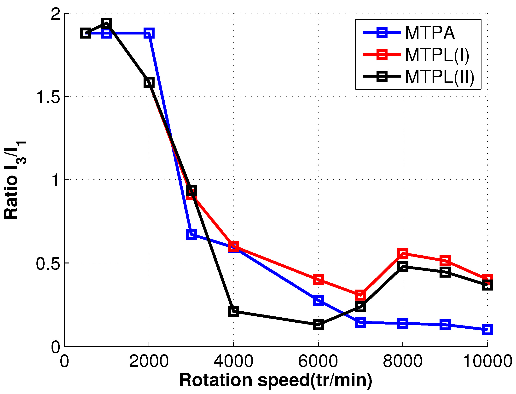
4.4.2. Optimal Currents at High Speeds

In this part, the optimal bi-harmonic current vectors are presented in Table 4. In grey columns are given the results for MTPL(I) and in the other columns the results for MTPL(II).
In both strategies, the current density decreases as the speed increases in order to keep losses within the admissible limits. In fact, this reduction will not affect only copper losses, but PM and iron losses, as well, which depend also on frequency. The voltage reaches the allowed peak value (48 V) for all speeds in MTPL(I), but this is not the case for MTPL(II). The results show a significant variation in the repartition between the current harmonics for both MTPL(I) and MTPL(II), as shown in Figure 6.

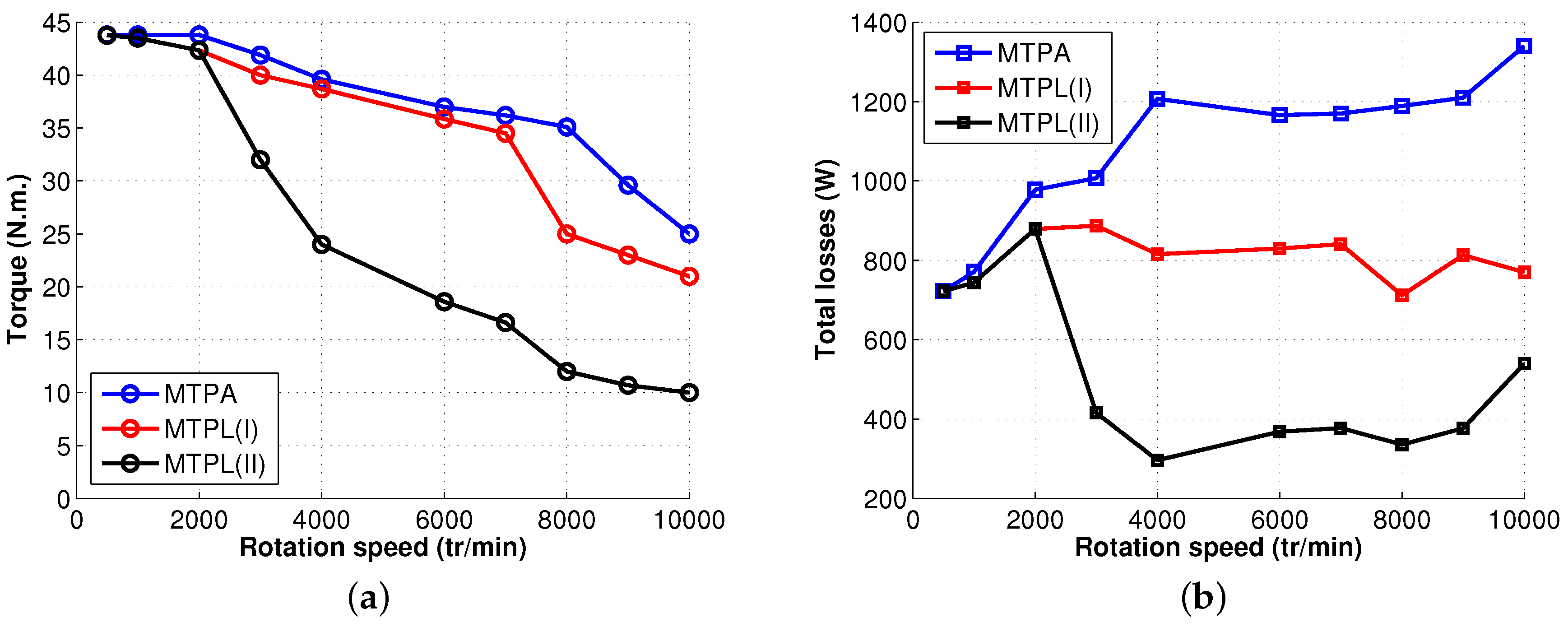
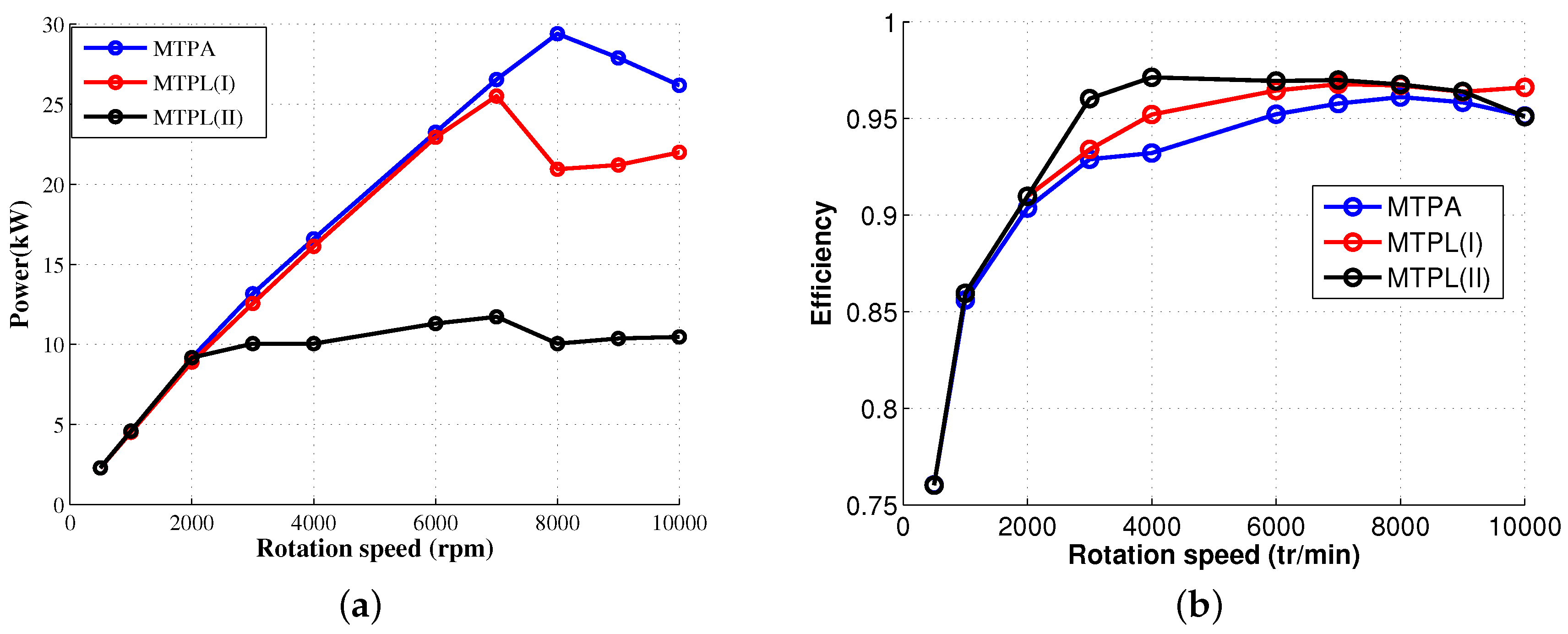
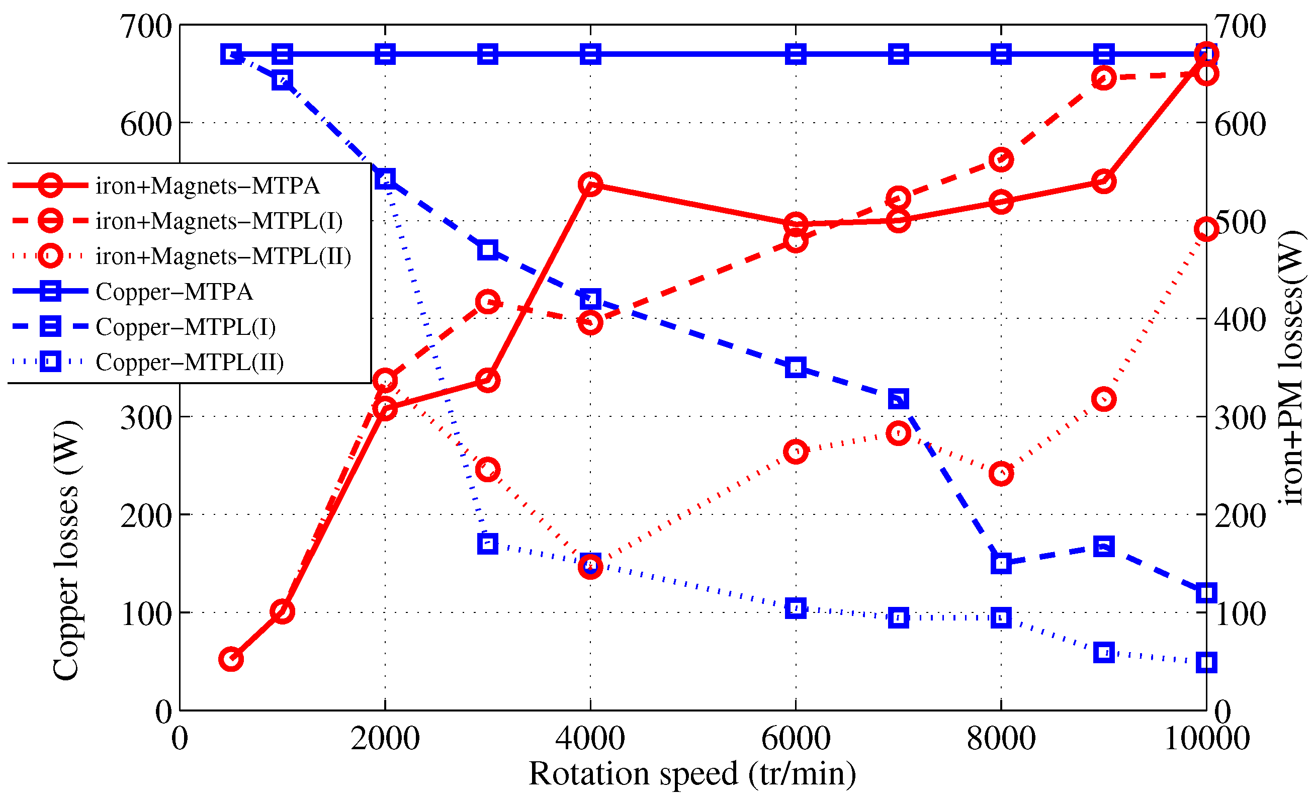
4.4.3. Torque, Losses and Efficiency

The resulting torque and total losses for each rotation speed are presented in Figure 8. Neglecting PM and iron losses at low speed and taking into account that the voltage peak value is not reached, we have MTPA = MTPL for all speeds <2000 rpm. The current density is 10 A/mm 2 , as long as the other constraints are verified. This is why we have equal total losses for 500 rpm and 1000 rpm for both strategies.
In the cases of the MTPA and MTPL(I) strategies, the voltage constraint is active at high speeds (the peak value is equal to 48 V), whereas for MTPL(II), the required power (10 kW), for steady state operations, does not make use of the full DC bus, as we can see in Table 3. This power is much lower than the power that can be produced in the MTPA strategy, as shown by Figure 8a. The MTPL(I) defines a new torque/speed characteristic of the machine with limited losses in the rotor and stator; MTPL(II) represents a new strategy with a limited power, as shown in Figure 10a.
For all of the control strategies, copper losses, iron losses and PM losses have been evaluated. Iron losses are calculated according to the model presented in Appendix A. Figure 9 shows the repartition of losses between PM, copper and iron, and Figure 10 displays the efficiency.
According to Figure 9, in the MTPA strategy (copper-MTPA curve), a constant current density is maintained at 10 A/mm 2 all over the operation speed range: this is reflected by constant high copper losses in the speed range equal to 670 W. Given that there are no constraints on total losses, they increase from 722 W at 500 rpm and reach 1340 W at 10,000 rpm (Figure 8). It is possible to accept this doubling only during transient operations. Concerning MTPL(I), copper losses decrease from 670 W at 500 rpm to reach 120 W at 10,000 rpm, and as a result, the total losses comply with the losses thresholds (900 W, 800 W for stator losses and 100 W for rotor losses) (Figure 9): the machine will be able to work in these conditions with an acceptable level of temperatures for the permanent magnet and the insulation of copper. The results show an improvement of efficiency in the MTPL(I) strategy compared to the MTPA strategy according to Figure 10b. As there are many degrees of freedom, there are many current vectors, which can be found for a given output power. MTPL(II) aims to find among these solutions this one minimizing the losses in the machine. In other words, MTPL(II) can guarantee the maximum efficiency for a given output power. The optimal currents for this strategy are given in Table 4. In the case of this study, a 10-kW output power is obtained, and a higher efficiency is obtained with this strategy according to Figure 10. For every power less than the power achieved by the MTPA strategy (30-kW maximum according to Figure 10b), this strategy can be applied in order to find the optimal currents in the constant power range while maximizing the efficiency. Consequently, MTPL(II) is a novel approach to control machines in the constant power region in cases of many freedom degrees.

5. Conclusions

A five-phase bi-harmonic machine whose torque can be controlled by acting separately on two harmonics of current, each one in a different ( α , β ) frame, has been presented. The potentialities of the machine have been explored, under two levels of current densities (5 A/mm 2 for steady states and 10 A/mm 2 for transient operations), in areas of the torque/speed plane where different limitations are found in traction drives: maximum voltage from the supply at high speeds, copper losses in the stator, iron losses separately in the stator and rotor and permanent magnet losses in the rotor.
New control MTPL strategies (Maximum Torque Per Losses), taking into account not only copper losses, but with more complexity, iron and permanent magnet losses calculated from finite element software with non-sinusoidal currents, have been defined for a machine with a non-sinusoidal magnetic flux density. MTPL strategies show results quite different from those obtained with the maximum torque per ampere strategy, which considers only copper losses. Using MTPL, efficiency is increased and the protection of the machine against breakdown due to over-heating is considered. Nevertheless, MTPA with high current densities and a voltage limitation can also be used for transient operation as long as maximum temperatures are not reached. These promising results validate the interest of making a prototype based on this concept for the practical implementation of control laws whose implementation in the numerical prototype is currently almost impossible because of time calculations. With the prototype, it will be possible to verify in real time the effective performances calculated during the optimization process in steady states. Then, it will also be possible to elaborate control laws adapted for transient operations, which still cannot be simulated with acceptable duration with virtual numerical modeling necessitating the non-linear finite element method. Because of the high number of freedom degrees, the constraints and the non-linear magnetic phenomena due to bi-harmonic supply, optimization tool, called EGO, using FEM modeling has been introduced. The results of the EGO method have proven, with acceptable durations for simulations, the potentialities of the machine and the possibilities to choose different strategies depending on the level of acceptable losses for the required torque.
More generally, we have shown in the paper that with this kind of new “bi-harmonic” machine, it is possible to adopt three different strategies of control, which lead to different performances, each one with its drawbacks and advantages. The choice between these three strategies depends on the objective assigned to the machine, which is intended to be used in the transportation drive. Sometimes, it is not the efficiency that is important, but the ability to produce a high torque: it will be a transient operation whose duration will depend on the initial conditions of the temperatures and of the choice of cooling. Sometimes, it is the efficiency that is important without the low requirement in terms of dynamics (low reserve of power).

Author Contributions

The paper was a collaborative effort between the authors. The authors contributed collectively to the theoretical analysis, modeling, simulation, and manuscript writing and revision.

Conflicts of Interest

The authors declare no conflict of interest.

Abbreviations

The following abbreviations are used in this manuscript:
( α 1 , β 1 ) subspace associated with the primary machine defined by Concordia transformation
( α 3 , β 3 ) subspace associated with the secondary machine defined by Concordia transformation
φ 1 , φ 3 phase of first and third harmonic of current with first and third harmonic of electromotive force as references
Ψflux linked in a phase of the machine
C N Concordia matrix
E 1 (resp. E 3 )first (resp. third) harmonic electromotive force amplitude
I 1 (resp. I 3 )first (resp. third) harmonic current force amplitude
IPMInternal Permanent Magnet
SPMSurface Permanent Magnet
JRMS current density
T e m torque produced by the machine
PMPermanent magnet
L o s s e s s t a t o r total losses in the stator (copper and iron losses)
L o s s e s r o t o r total losses in the rotor (iron and permanent magnet losses)
N p p number of slots per pole and per phase
P e x p ( x ) cumulative distribution function
pnumber of pairs of poles
S c o n d the conductor area
V p h a s e voltage across a phase of the machine
V D C DC bus voltage

Appendix A. Iron Losses Calculation

The model used to estimate the volume density of the iron losses [50]:
P i r o n = f ( B , d B d t ) = 1 π K h H i r r d B d t + 1 2 π 2 K f d B d t 2 + 1 8 . 763 K e x c d B d t 1.5

References

  1. Levi, E. Multiphase electric machines for variable-speed applications. IEEE Trans. Ind. Electron. 2008, 55, 1893–1909. [Google Scholar] [CrossRef]
  2. Letellier, P. High Power Permanent magnet machines for electric propulsion drives. In Proceedings of the 3rd International Symposium on All Electric Ship, Paris, France, 26–27 October 2000; pp. 126–132.
  3. Thongam, J.; Tarbouchi, M.; Okou, A.; Bouchard, D.; Beguenane, R. Trends in naval ship propulsion drive motor technology. In Proceedings of the Electrical Power & Energy Conference (EPEC), Halifax, NS, Canada, 21–23 August 2013; IEEE: New York, NY, USA, 2013; pp. 1–5. [Google Scholar]
  4. Bennett, J.; Mecrow, B.C.; Atkinson, D.J.; Atkinson, G. Safety-critical design of electromechanical actuation systems in commercial aircraft. Electr. Power Appl. IET 2011, 5, 37–47. [Google Scholar] [CrossRef]
  5. Cao, W.; Mecrow, B.C.; Atkinson, G.J.; Bennett, J.W.; Atkinson, D.J. Overview of electric motor technologies used for more electric aircraft (MEA). IEEE Trans. Ind. Electron. 2012, 59, 3523–3531. [Google Scholar]
  6. Huang, X.; Goodman, A.; Gerada, C.; Fang, Y.; Lu, Q. Design of a five-phase brushless DC motor for a safety critical aerospace application. IEEE Trans. Ind. Electron. 2012, 59, 3532–3541. [Google Scholar] [CrossRef]
  7. Bojoi, R.; Cavagnino, A.; Tenconi, A.; Vaschetto, S. Control of Shaft-Line-Embedded Multiphase Starter/Generator for Aero-Engine. IEEE Trans. Ind. Electron. 2016, 63, 641–652. [Google Scholar] [CrossRef]
  8. Parsa, L.; Toliyat, H.A. Fault-tolerant interior-permanent-magnet machines for hybrid electric vehicle applications. IEEE Trans. Veh. Technol. 2007, 56, 1546–1552. [Google Scholar] [CrossRef]
  9. Mohammadpour, A.; Parsa, L. Global fault-tolerant control technique for multiphase permanent-magnet machines. IEEE Trans. Ind. Appl. 2015, 51, 178–186. [Google Scholar] [CrossRef]
  10. Chen, Q.; Liu, G.; Gong, W.; Zhao, W. A new fault-tolerant permanent-magnet machine for electric vehicle applications. IEEE Trans. Magn. 2011, 47, 4183–4186. [Google Scholar] [CrossRef]
  11. Zheng, P.; Wu, F.; Lei, Y.; Sui, Y.; Yu, B. Investigation of a novel 24-slot/14-pole six-phase fault-tolerant modular permanent-magnet in-wheel motor for electric vehicles. Energies 2013, 6, 4980–5002. [Google Scholar] [CrossRef]
  12. Arashloo, R.S.; Romeral Martinez, J.L.; Salehifar, M.; Moreno-Eguilaz, M. Genetic algorithm-based output power optimisation of fault tolerant five-phase brushless direct current drives applicable for electrical and hybrid electrical vehicles. Electr. Power Appl. IET 2014, 8, 267–277. [Google Scholar] [CrossRef]
  13. Scuiller, F.; Semail, E.; Charpentier, J.F.; Letellier, P. Multi-criteria-based design approach of multi-phase permanent magnet low-speed synchronous machines. Electr. Power Appl. IET 2009, 3, 102–110. [Google Scholar] [CrossRef] [Green Version]
  14. Aslan, B.; Semail, E.; Korecki, J.; Legranger, J. Slot/pole combinations choice for concentrated multiphase machines dedicated to mild-hybrid applications. In Proceedings of the IECON 2011—37th Annual Conference on IEEE Industrial Electronics Society, Melbourne, Australia, 7–10 November 2011; pp. 3698–3703.
  15. Sui, Y.; Zheng, P.; Wu, F.; Yu, B.; Wang, P.; Zhang, J. Research on a 20-slot/22-pole five-phase fault-tolerant pmsm used for four-wheel-drive electric vehicles. Energies 2014, 7, 1265–1287. [Google Scholar] [CrossRef]
  16. Bojoi, R.; Cavagnino, A.; Cossale, M.; Tenconi, A. Multiphase starter generator for 48 V mini-hybrid powertrain: Design and testing. In Proceedings of the 2014 International Symposium on Power Electronics, Electrical Drives, Automation and Motion (SPEEDAM), Ischia, Italy, 18–20 June 2014; pp. 1319–1324.
  17. Aslan, B.; Savinois, O.; Mipo, J.C.; Farah, P.S. Comparison between 5 and 6 Phases Claw Pole Alternator for Automotive Application. In Proceedings of the 2014 IEEE Vehicle Power and Propulsion Conference (VPPC), Delft, The Netherlands, 18–20 June 2014; pp. 1–5.
  18. Jordan, S.; Manolopoulos, C.D.; Apsley, J.M. Winding Configurations for Five-Phase Synchronous Generators with Diode Rectifiers. IEEE Trans. Ind. Electron. 2016, 63, 517–525. [Google Scholar] [CrossRef]
  19. Scuiller, F.; Zahr, H.; Semail, E. Maximum reachable torque, power and speed for five-phase SPM machine with low armature reaction. IEEE Trans. Energy Convers. 2016, 31, 959–969. [Google Scholar] [CrossRef]
  20. Kestelyn, X.; Semail, E. A vectorial approach for generation of optimal current references for multiphase permanent-magnet synchronous machines in real time. IEEE Trans. Ind. Electron. 2011, 58, 5057–5065. [Google Scholar] [CrossRef] [Green Version]
  21. Zhao, P.; Yang, G. Torque density improvement of five-phase PMSM drive for electric vehicles applications. J. Power Electron. 2011, 11, 401–407. [Google Scholar] [CrossRef]
  22. Gong, J.; Aslan, B.; Gillon, F.; Semail, E. High Speed Functionality Optimizaion of Five-Phase PM Machine Using 3rd Harmonic Current. Int. J. Comput. Math. Electr. Electron. Eng. 2014, 33, 879–893. [Google Scholar] [CrossRef]
  23. Wang, K.; Zhu, Z.; Ombach, G. Torque enhancement of surface-mounted permanent magnet machine using third-order harmonic. IEEE Trans. Magn. 2014, 50, 104–113. [Google Scholar] [CrossRef]
  24. Sadeghi, S.; Mohammadpour, A.; Parsa, L. Design optimization of a high performance five-phase slotless PMSM. In Proceedings of the 2014 International Symposium on Power Electronics, Electrical Drives, Automation and Motion (SPEEDAM), Ischia, Italy, 18–20 June 2014; pp. 6–11.
  25. Yu, F.; Cheng, M.; Chau, K.T.; Li, F. Control and Performance Evaluation of Multiphase FSPM Motor in Low-Speed Region for Hybrid Electric Vehicles. Energies 2015, 8, 10335–10353. [Google Scholar] [CrossRef]
  26. Barrero, F.; Duran, M.J. Recent Advances in the Design, Modeling, and Control of Multiphase Machines— Part I. IEEE Trans. Ind. Electron. 2016, 63, 449–458. [Google Scholar] [CrossRef]
  27. Sun, Z.; Wang, J.; Jewell, G.W.; Howe, D. Enhanced optimal torque control of fault-tolerant PM machine under flux-weakening operation. IEEE Trans. Ind. Electron. 2010, 57, 344–353. [Google Scholar]
  28. Xuelei, S.; Xuhui, W.; Wei, C. Research on field-weakening control of multiphase permanent magnet synchronous motor. In Proceedings of the 2011 International Conference on Electrical Machines and Systems (ICEMS), Beijing, China, 20–23 August 2011; pp. 1–5.
  29. Sadeghi, S.; Guo, L.; Toliyat, H.A.; Parsa, L. Wide operational speed range of five-phase permanent magnet machines by using different stator winding configurations. IEEE Trans. Ind. Electron. 2012, 59, 2621–2631. [Google Scholar] [CrossRef]
  30. Lu, L.; Aslan, B.; Kobylanski, L.; Sandulescu, P.; Meinguet, F.; Kestelyn, X.; Semail, E. Computation of optimal current references for flux-weakening of multi-phase synchronous machines. In Proceedings of the IECON 2012—38th Annual Conference on IEEE Industrial Electronics Society, Montreal, QC, Canada, 25–28 October 2012; pp. 3610–3615.
  31. Mengoni, M.; Zarri, L.; Tani, A.; Parsa, L.; Serra, G.; Casadei, D. High-Torque-Density Control of Multiphase Induction Motor Drives Operating Over a Wide Speed Range. IEEE Trans. Ind. Electron. 2015, 62, 814–825. [Google Scholar] [CrossRef]
  32. Grandi, G.; Loncarski, J. Analysis of peak-to-peak current ripple amplitude in seven-phase PWM voltage source inverters. Energies 2013, 6, 4429–4447. [Google Scholar] [CrossRef]
  33. Levi, E. Advances in converter control and innovative exploitation of additional degrees of freedom for multiphase machines. IEEE Trans. Ind. Electron. 2016, 63, 433–448. [Google Scholar] [CrossRef]
  34. Aslan, B.; Korecki, J.; Vigier, T.; Semail, E. Influence of Rotor Structure and Number of Phases on Torque and Flux Weakening Characteristics of V-shape Interior PM Electrical Machine. J. Energy Power Eng. 2012, 6, 1461. [Google Scholar]
  35. Aslan, B.; Semail, E. New 5-phase concentrated winding machine with bi-harmonic rotor for automotive application. In Proceedings of the 2014 International Conference on Electrical Machines (ICEM), Berlin, Germany, 2–5 September 2014; pp. 2114–2119.
  36. Legranger, J.; Semail, B.; Semail, E. Polyphase Rotary Electrical Machine Having at Least Five Phases with Optimised Control. European Patent EP 2866344 (A2), 5 August 2015. [Google Scholar]
  37. Zahr, H.; Semail, E.; Scuiller, F. Five-phase version of 12slots/8poles three-phase synchronous machine for marine-propulsion. In Proceedings of the 2014 IEEE Vehicle Power and Propulsion Conference (VPPC), Coimbra, Portugal, 27–30 October 2014; pp. 1–6.
  38. Lyra, R.O.; Lipo, T.A. Torque density improvement in a six-phase induction motor with third harmonic current injection. IEEE Trans. Ind. Appl. 2002, 38, 1351–1360. [Google Scholar] [CrossRef]
  39. Lipo, T.A.; Lyra, R.O. Multi-Phase Electric Motor with Third Harmonic Current Injection. U.S. Patent 6,710,495, 23 March 2004. [Google Scholar]
  40. Abdelkhalik, A.; Masoud, M.; Barry, W. Eleven-phase induction machine: steady-state analysis and performance evaluation with harmonic injection. Electr. Power Appl. IET 2010, 4, 670–685. [Google Scholar] [CrossRef]
  41. Giurgea, S.; Zire, H.; Miraoui, A. Two-stage surrogate model for finite-element-based optimization of permanent-magnet synchronous motor. IEEE Trans. Magn. 2007, 43, 3607–3613. [Google Scholar] [CrossRef]
  42. Berbecea, A.; Kreuawan, S.; Gillon, F.; Brochet, P. A parallel multiobjective efficient global optimization: The finite element method in optimal design and model development. IEEE Trans. Magn. 2010, 46, 2868–2871. [Google Scholar] [CrossRef]
  43. El-Refaie, A.M. Motors/generators for traction/propulsion applications: A review. IEEE Veh. Technol. Mag. 2013, 8, 90–99. [Google Scholar] [CrossRef]
  44. Dajaku, G.; Spas, S.; Dajaku, X.; Gerling, D. Comparison of Two FSCW PM Machines for Integrated Traction Motor/Generator. In Proceedings of the IEEE International Electric Machines & Drives Conference (IEMDC), Coeur d’Alene, ID, USA, 10–13 May 2015; pp. 187–194.
  45. Kestelyn, X.; Semail, E. Vectorial Modeling and Control of Multiphase Machines with Non-salient Poles Supplied by an Inverter. In Control of Non-conventional Synchronous Motors; ISTE Ltd.: London, UK; John Wiley & Sons: New York, NY, USA, 2012; Chapter 7. [Google Scholar]
  46. Scuiller, F.; Semail, E.; Charpentier, J.F. General modeling of the windings for multi-phase ac machines. Eur. Phys. J. Appl. Phys. 2010, 50, 31102. [Google Scholar] [CrossRef] [Green Version]
  47. Zahr, H.; Semail, E.; Aslan, B.; Scuiller, F. Maximum Torque Per Ampere strategy for a biharmonic five-phase synchronous machine. In Proceedings of the 2016 International Symposium on Power Electronics, Electrical Drives, Automation and Motion (SPEEDAM), Anacapri, Italy, 22–24 June 2016; pp. 91–97.
  48. Rathnayake, R.; Dutta, R.; Fletcher, J.; Xiao, D. Modified efficiency optimization control for fractional slot concentrated wound interior permanent magnet synchronous generators. In Proceedings of the IECON 2015—41st Annual Conference of the IEEE Industrial Electronics Society, Yokohama, Japan, 9–12 November 2015.
  49. Saur, M.; Lehner, B.; Hentschel, F.; Gerling, D.; Lorenz, R.D. DB-DTFC as loss minimizing control for synchronous reluctance drives. In Proceedings of the IECON 2015—41st Annual Conference of the IEEE Industrial Electronics Society, Yokohama, Japan, 9–12 November 2015.
  50. Lin, D.; Zhou, P.; Fu, W.; Badics, Z.; Cendes, Z. A dynamic core loss model for soft ferromagnetic and power ferrite materials in transient finite element analysis. IEEE Trans. Magn. 2004, 40, 1318–1321. [Google Scholar] [CrossRef]
Figure 1. (a) Representation of the original bi-harmonic machine with 5 phases/20 slots/8 poles; (b) magnetic flux density map at no load.
Energies 09 00952 g001
Figure 2. (a) Emf waveform of the bi-harmonic machine at 1000 rpm; (b) magnitude of the emf harmonics.
Energies 09 00952 g002
Figure 3. Projection of the back-EMF in: (a) ( α 1 , β 1 ) primary sub-space; (b) ( α 3 , β 3 ) the secondary sub-space.
Energies 09 00952 g003
Figure 4. (a) Emf and current; (b) rated torque resulting from the interaction between emf and current.
Energies 09 00952 g004
Figure 5. Comparison between Equation (4) and FE calculation.
Energies 09 00952 g005
Figure 6. Variation of ratio I 3 / I 1 for the three control strategies.
Energies 09 00952 g006
Figure 7. Inputs and outputs of studied global model of the bi-harmonic PM five-phase machine.
Energies 09 00952 g007
Figure 8. Comparison between the three control strategies: (a) torque; (b) total losses.
Energies 09 00952 g008
Figure 9. Copper losses, PM and iron losses versus speed.
Energies 09 00952 g009
Figure 10. (a) Power versus speed; (b) Efficiency versus speed.
Energies 09 00952 g010
Table 1. Machine parameters.
ParameterValueParameterValue
Stator diameter130 mmAir gap1 mm
Magnet width25.56 mmMagnet height4 mm
Slot depth20.52 mmStator yoke5.8 mm
Hole width12.7 mmHole maximum depth6.34 mm
Magnet bridge1.25 mmLength92.6 mm
Magnet typeNdFeB N40UHSteelFe-Si M270-35A
Rated speed at 5 A/mm 2 3700 rpmRated torque at 5 A/mm 2 32.7 N.m.
Rated power at 5 A/mm 2 12.7 kWpeak power at 5 A/mm 2 19.6 kW
Maximum Torque for 10 A/mm 2 at low speed44 N.m.Maximum speed14,000 rpm
Peak power for 10 A/mm 2 29.4 kW
Table 2. Optimal currents for the MTPA strategy with J = 10 A/mm 2 .
SpeedFirst HarmonicThird Harmonic I 1 ( A ) φ 1 I 3 ( A ) φ 3 Voltage PeakTorque
(rpm)Frequency (Hz)Frequency(V)(N.m.)
50033100176−0.04330.80.1512.543.8
100066200176−0.04330.80.1521.243.8
2000133400176−0.04330.80.154243.8
2500167500308.450.47210.660.144842.1
30002006003100.51208.30.0947.541.9
4000266800321.10.95190.80.274839.6
600040012003601.199.50.34837
70004671400369.20.5956.640.94836.2
800053316003701.12510.314835.1
90006001800370.420.648.061.484829.6
10,0006672000372.11.2137.10.454825
Table 3. Optimal resolution of MTPL(I) strategy at low speed.
Speed (rpm) I 1 ( A ) φ 1 I 3 ( A ) φ 3 J (A/mm 2 )Voltage Peak (V)
500176−0.039330.80.151012.6
1000167.80.026325.40.229.825.2
20001780.349282.80.24943.8
Table 4. Optimal resolution of MTPL strategy at high speed: grey column, MTPL(I); white column, MTPL(II).
Speed (rpm) I 1 ( A ) φ 1 I 3 ( A ) φ 3 J (A/mm 2 )Voltage Peak (V)
3000229.4136.40.5360.42209.1127.70.290.278.31547.830.5
4000250169.90.530.5515035.70.160.547.84.6447.519.8
6000250146.30.550.54100190.5117.23.9547.526.3
7000245.85137.140.480.6275.532.50.411.316.893.747.2724.97
8000152.5126.90.6518560.70.841.354.673.7647.320.6
9000109.47101.390.520.9256.2545.250.661.265.322.9746.7227.83
10,000146.61040.4890.98658.938.211.284.232.6947.432

