Article

Development and Simulation of a Type of Four-Shaft ECVT for a Hybrid Electric Vehicle

National Engineering Laboratory for Automotive Electronic Control Technology, Shanghai Jiao Tong University, 800 Dongchuan Rd, Shanghai 200240, China
*
Author to whom correspondence should be addressed.
Energies 2016, 9(3), 141; https://doi.org/10.3390/en9030141
Submission received: 31 July 2015 / Revised: 24 January 2016 / Accepted: 28 January 2016 / Published: 27 February 2016
(This article belongs to the Special Issue Advances in Plug-in Hybrid Vehicles and Hybrid Vehicles)

Abstract

:
In hybrid electric vehicles with power-split configurations, the engine can be decoupled from the wheel and operated with improved fuel economy, while the entire efficiency of the powertrain is affected by the circular electric power flow. Two planetary gear (2-PG) sets with adding brakes/clutches, namely a type of four shaft elelctric continuously variable transmission (ECVT) can provide multi-mode operation for the powertrain and extend the efficient area. First, a conventional 2-PG AT (Automatic Transmission) architecture is investigated. By analyzing and comparing the connection and operating modes based on the kinematic relationship and lever analogy, a feasible four-shaft ECVT architecture with two brakes and two simplified versions are picked. To make a trade-off between fuel economy and configuration complexity, an instantaneous optimal control strategy based on the equivalent consumption minimization strategy (ECMS) concept is then developed and employed as the unified optimization method in the simulations of three different configurations. Finally, the simulation results show that the simplified versions are suboptimal sets and the fuel economy is sacrificed by the limits of different modes. From the viewpoint of concept design, a multi-mode power-split configuration is more suitable for hybrid electric vehicles. This research applied a systematic methodology from concept design to energy management optimization, which can provide the guidelines for researchers to select a suitable multi-mode power-split hybrid powertrain.

1. Introduction

Power-split hybrid vehicles dominate the blooming hybrid electric vehicle market. The core of the power-split powertrain is the hybrid transmission composed of a planetary gear set which splits and couples the mechanical power from the engine and two electric machines. The configuration can take advantages of both series and parallel hybrid vehicles [1], and is the most promising scheme to achieve the target of a deep reduction of emission and fuel consumption.
The market has also certified the performance of power-split powertrain. Two representative power-split hybrid vehicle models are Toyota’s Prius and Chevy Volt. The former uses an input-split configuration with single planetary gear (PG) set [2,3], while the latter uses an output-split configuration with a single PG as well, and has three clutches and four operating modes.
For power-split hybrid vehicles with a single operating mode, the power components can be easily operated close to the speed limits [4]. Using two planetary gear sets, or more, can provide more operation modes when clutches are used [5,6,7,8]. Analyzing all the feasible modes to find out which ones are used most frequently is necessary to explore the potential of the configuration and can provide the basis for simplified designs [2,9,10,11].
In order to evaluate the potential of fuel economy improvement and emission reduction, optimal control strategies for energy management should be firstly designed. For the supervisory control strategy of hybrid electric vehicles (HEVs), various methods have been studied and implemented [12]. Load-leveling control sets several thresholds for the engine operation, which is easy to be implemented. However, it is heuristic and empirical to reveal the full potential of fuel economy improvement. As a global optimization problem, dynamic programming (DP) can give the optimal solution over the whole time horizon with the knowledge of driving cycle; however, the greatest shortcoming is the heavy computational load which increases exponentially with state variables [13]. In order to solve the problem of non-causality in deterministic dynamic programming, stochastic dynamic programming can be applied to optimization which uses Markov chains to represent the drive cycle distribution as [4]. The equivalent consumption minimization strategy (ECMS) is an instantaneous optimization which optimizes the instantaneous fuel cost at each time step. Although it is a global optimization algorithm, it is easier to achieve a nearly-global optimization [14,15]. One near-optimal method is developed and applied to identify the optimal powertrain parameters of a single planetary gear type EVTs based on the analysis of the efficiency of powertrain components and beat power-weighted efficiency from the given driving cycle [16]. The simulation results showed that adding clutches to enabled multiple modes is beneticial compared with single-mode designs.
The paper focuses on the alternative configuration design for power-split hybrid electric vehicle based on the 2-PG conventional automatic transmission (AT). The paper outline is as follows. In Section 2 the basic kinematic characteristics of 2-PG AT are analyzed representatively and then the new four shaft ECVT configuration which can provide multi-mode for vehicle propulsion is defined step by step. The optimal control strategy based on ECMS concept for the multi-mode elelctric continuously variable transmission (ECVT) is developed in Section 3. Three different configurations are simulated using the same control strategy framework. In Section 4, the simulation results are analyzed in detail, especially the trade-off between configuration complexity and fuel economy.

2. ECVT Configuration Design

There are six nodes in total, for a 2-PG sets in a power-split vehicles. In order to design a valid power-split transmission, both PG sets are required to make two of their nodes connected. Therefore, the transmission has two degrees of freedom (DOF), which is the advantage of a power-split configuration.

2.1. Planetary Gear Set

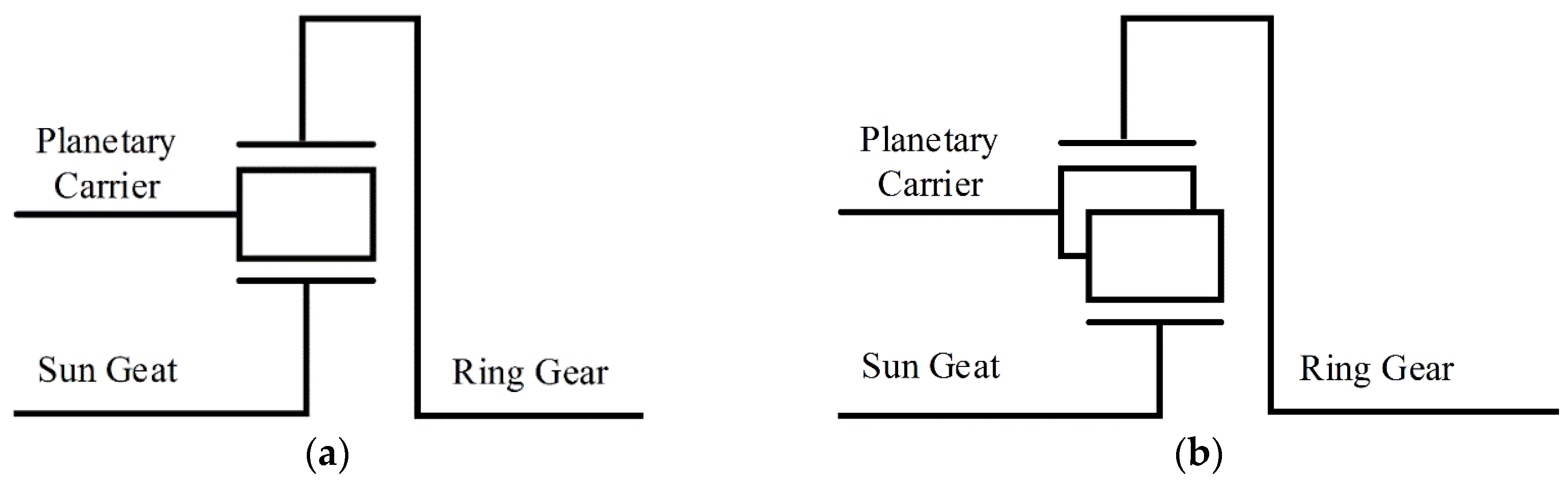
2.1.1. Simple Gear Set

Simple gear set contains one pinion gear meshing with the ring gear and sun gear as shown in 
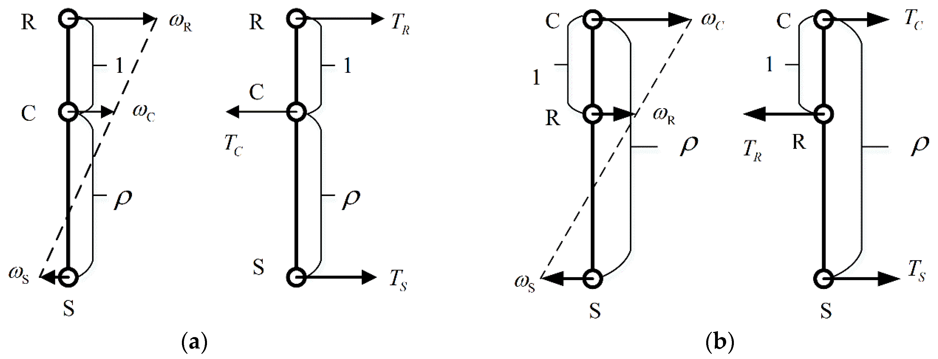
Figure 1a. According to the kinematics of PG, the speed relationship and torque relationship of each node can be shown as follows, which is much more obvious from the lever diagram [17]:
ω S + ρ ω R = ( 1 + ρ ) ω C
T S = F r S
T R = F r R
T C = F ( r R + r S ) = T R + T S
TR, TS, TC are the torque of ring gear node, sun gear node, and carrier gear node , where F is the gear meshing force in the planetary gear set. rS, rR are the radii of sun gear and ring gear, respectively, and are proportional to ZS, ZR. The direction is shown as in Figure 2a.

2.1.2. Compound Gear Set

Compared with simple gear set, there is a pair of pinion gears between the ring gear and sun gear as shown in Figure 1b. Similarly, the compound planetary gear set also has a linear speed relationship and linear steady-state torque relationship according to the kinetic and dynamics of the configuration, which is also shown as the lever diagram in Figure 2b.
ω S + ( ρ 1 ) ω C = ρ ω R
T S = F r S
T R = F r R
T C = F ( r R + r S ) = T R + T S
The equations of speed relationship and torque relationship indicate that both the simple PG and compound PG has two DOF (Degrees Of Freedom).

2.2. 2-PG Automotive Transmission

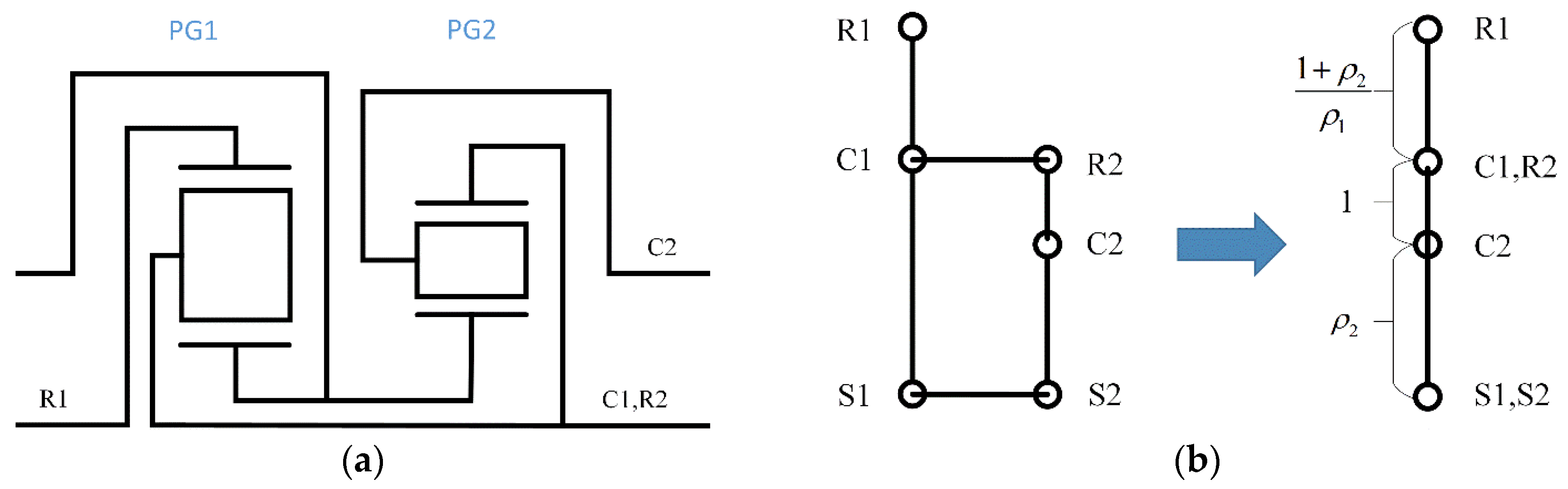
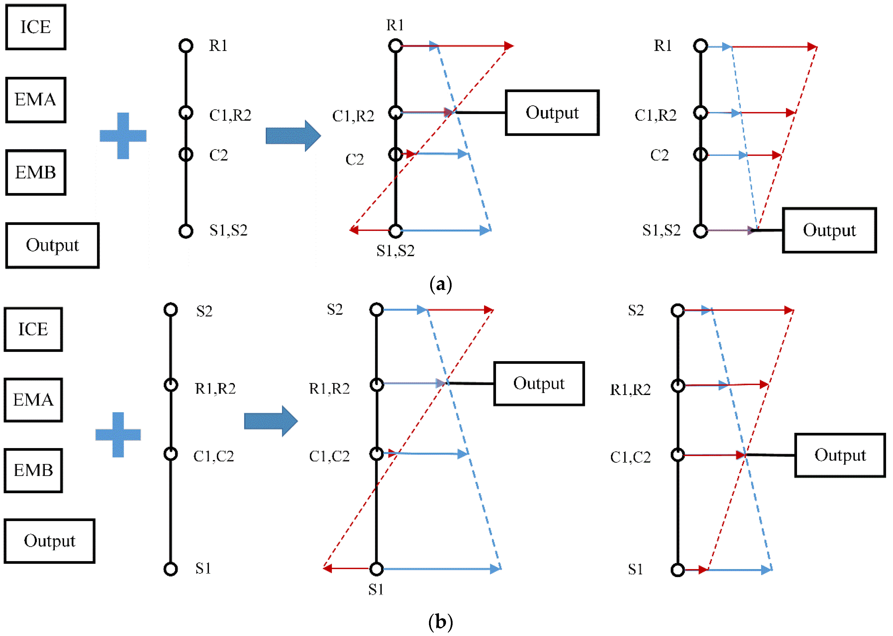
2.2.1. Simpson Automotive Transmission

The Simpson autuomotive transmission consists of two planetary gearsets. Both gearsets share a longer sun gear. The planet carrier of the first gearset (C1) is in synchronism with the second gearset’s ring gear (R2) and both in synchronism with the output shaft. The configuration is shown in Figure 3a. According to the principles introduced in Section 2.1, the configuration can be analyzed as a combined lever diagram based on the kinematic euqations. The lever diagram is shown in Figure 3b.

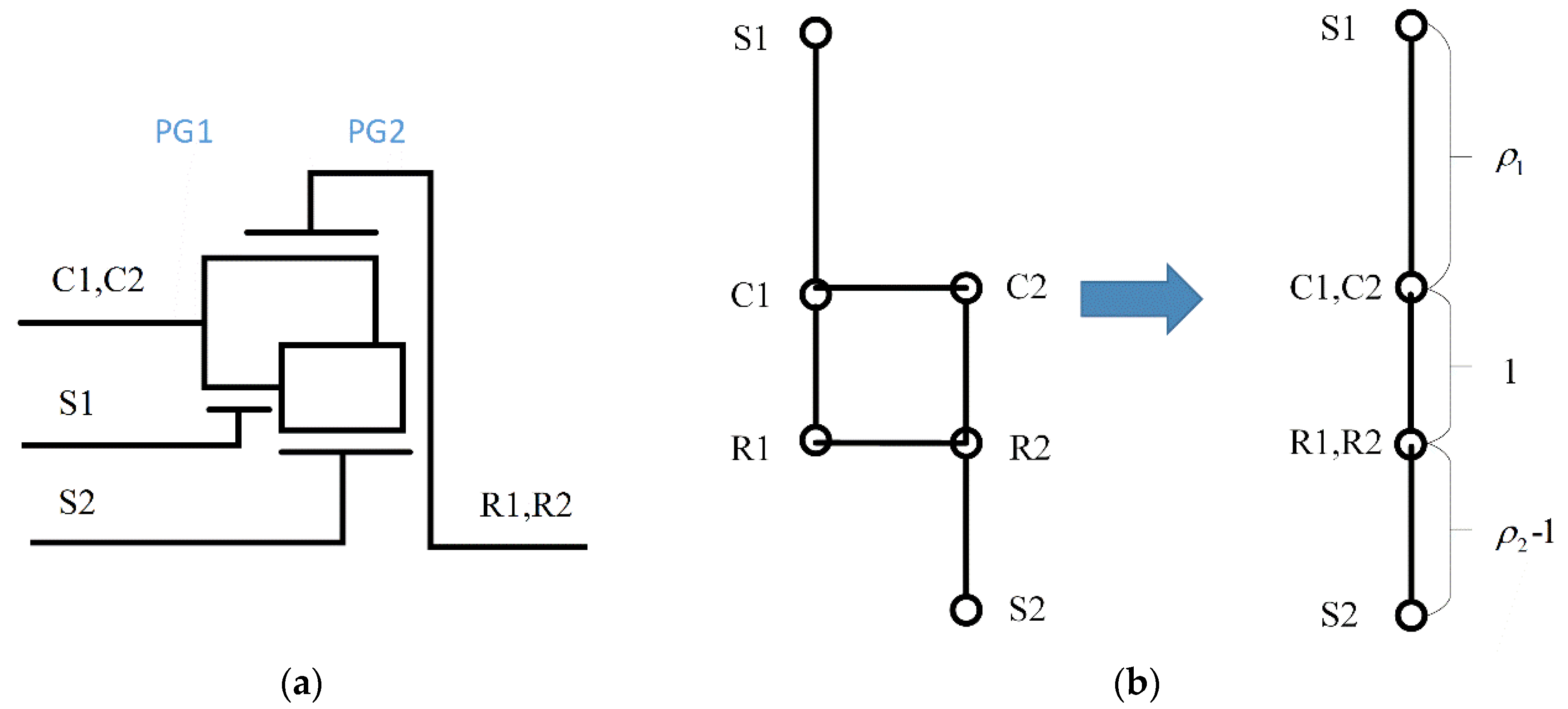
2.2.2. Revigneaux Automotive Transmission

The Ravigneaux gearset is a two planetaer gear sets, which is commonly used in automatic transmissions. The configuration has two sun gears, a large one(S1) and a small one(S2), and a single planet carrier, holding two sets of planetary gears(C1, C2) as shown in Figure 4a. The Ravigneaux gear set improves upon the Simpson gearset which has two complete planetary gearsets. Based on the lever analogy we can combine the lever diagram from the connection relationship as shown in Figure 4b. This method of simplification is also used in the 2-PG configuration analysis in following part.

2.3 Four-Shaft Elelctric Continuously Variable Transmission (ECVT) Configuration

The 2-PG configuration implemented as the hybrid transmission couples the power from power elements, e.g., the inner combustion engine (ICE) or electric machines (EMs), to the output shaft (Output). Therefore, the possible design of the four-shaft E-CVT configuration is the permutation of the four nodes and the four elements (ICE, EMA (Electric Machine A), EMB (Electric Machine B), and Output) as much as 4! = 24. However, considering the kinematic characteristics of the 2-PG transmission and the constraints of the power elements (e.g., maximum speed and maximum torque), the feasible designs are screened as below.

2.3.1. Basic Configuration without Clutches

Design rules:
  • To guarantee continuous output power to wheels whenever the power elements operating modes, the output shaft should be at the connected nodes of 2-PGs.
  • According to the speed equations which demonstrate the linear relationship between the four nodes, the connection of the power elements should conform to the speed limitation.
  • ICE outputs positive torque or idles with the same speed direction when vehicles are driving; two EMs can work in four quadrants as motor or generator according to the kinetic relationships with ICE and power demand.
According to the design rules, the speed relationship on the lever diagram can be obtained easily, assuming that the speeds of the output node and one of the end nodes are fixed.
For the Simpson 2-PG configuration, the output shaft can be connected at C1 (R2) or S1 (S2). When C1 (R2) is set as an output node, either R1 or S1 (S2) node speed is maximized; then the other two nodes speeds can be calculated. The diagrams of the connections and speed relationships are shown in Figure 5a, where the red line and blue line represent the possible speed relationships, respectively. It is obvious to conclude from the lever diagram that:
(a)
Compared with the end node S1 (S2), the output shaft would better connect to the middle node C1 (R2) because the other two nodes’ speed will decrease to avoid overspeed.
(b)
When C1 (R2) is determined as the output node, the further the other three nodes are away from the output, the greater the speed difference that is possible for different operating conditions, e.g., the S1 node speed even changes directions for red line and blue line.
(c)
According to the linear speed relationship with output speed, the connection sequence should be under the constraints of maximum speed for the ICE and EMs.
Similarly, the Ravigneaux 2-PG configuration has two feasible connections that both locate the output shaft on the middle node of the PG as shown in Figure 5b. Therewith, the ICE and EMs should lay out in accordance to their speed relationship and constraints.
Therefore, the output shaft prefers to locate at the middle connected node with ICE, instead of the nearest, while EMs should lay out on the other two nodes whose lever lengths are proportional to their maximum speed limit. The Simpson configuration and the Ravigneaux configuration have similar designs which are analyzed above; the only difference is the planetary gear ratio ρ1 and ρ2 which can be considered as another tuning parameter during the design process.
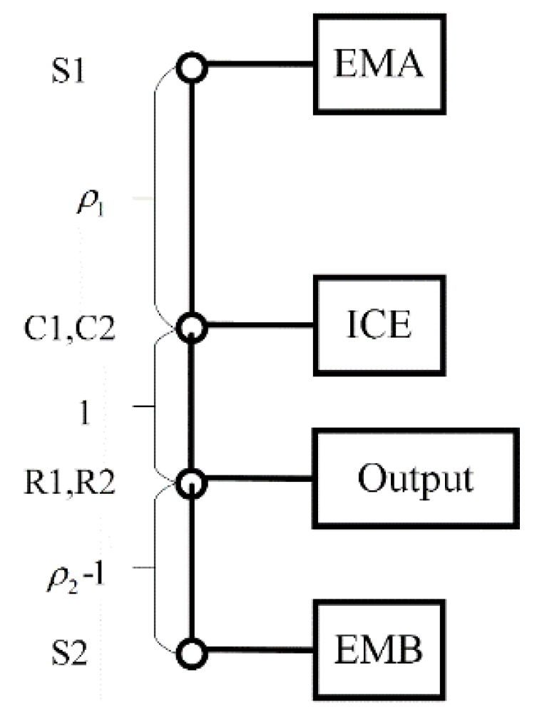
As a result, the typical design is picked that transforms the basic Ravigneaux configuration into a new four-shaft hybrid transmission working as a power-split device, as shown in Figure 6. A similar design has also been investigated in [18] as a novel hybrid transmission, while without a clutch between the engine and the carrier gears’ control strategy has to balance the torques from two electric machines limited to the engine static or kinematic brake torque.

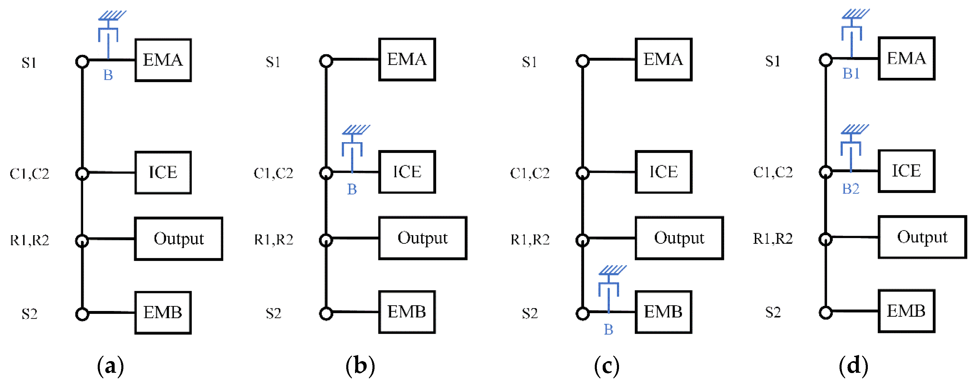
2.3.2. Multi-Mode Configuration with Brakes

Automotive transmissions for conventional vehicles with two shafts (input and output) can achieve several gear positions with the cooperation of clutches/brakes. Principally, adding clutches/brakes on the basic configuration above can also gain more operating modes like that below, in Figure 7.
The added brake locks the node when actuated, while the speed decreases to zero immediately and the brake can provide torque even larger than the component connected to the node. So although the adding brake reduces one DOF, on the other side it can provide one more operational mode. The configuration (a) in Figure 7 has two hybrid modes which are the power-split mode and the parallel mode; configuration (b) in Figure 7 has enhanced EV driving ability when ICE is locked and reduces the engine spinning loss; configuration (c) in Figure 7 is quite like (a) while the locked EMB is powerful than EMA. Considering the drive ability, both (a) and (b) can be considered as candidates with multi-mode configurations with brakes. The configuration (d) in Figure 7 is multi-mode, both while hybrid driving and pure electric driving with enhanced drive capacity.
The state-space representation for dynamics of a 2-PG powertrain in [4] is adopted to derive the equations describing the multi-mode configuration. The state-space equations are also the theory of the powertrain model, whose dynamics, associated with the energy management in Section 3, are of a relatively low-bandwidth nature. The transient dynamics of clutches and engine are related to higher-bandwidth and always taken into consideration in vehicle drivability [19]. The gear and shaft losses are ignored here, which has been confirmed by some peers’ previous research work [20].

(1) Power-Split Mode:

[ ω ˙ OUT ω ˙ ICE ω ˙ EM 1 ω ˙ EM 2 F 1 F 2 ] = [ m R 2 K 2 + I C 1 0 0 0 R 1 + S 1 R 2 S 2 0 I ICE + I R 1 0 0 R 1 R 2 0 0 I EM 1 + I S 1 0 S 1 0 0 0 0 I EM 2 + I S 2 0 S 2 R 1 + S 1 R 1 S 1 0 0 0 R 2 S 2 R 2 0 S 2 0 0 ] 1 [ T f T ICE T EM 1 T EM 2 0 0 ]

(2) Parallel Mode:

[ ω ˙ OUT ω ˙ ICE ω ˙ EM 2 F 1 F 2 ] = [ m R 2 K 2 + I C 1 0 0 R 1 + S 1 R 2 S 2 0 I ICE + I R 1 0 R 1 R 2 0 0 I EM 2 + I S 2 0 S 2 R 1 + S 1 R 1 0 0 0 R 2 S 2 R 2 S 2 0 0 ] 1 [ T f T ICE T EM 2 0 0 ]

(3) Single-EM Mode:

Single EM is the particular case in parallel mode or dual-EM mode, when the ICE or EMA idles. Comparing the ratio between output speed and EMB speed, parallel mode can provide relatively larger torque while at low vehicle speed, which is proper for the single EM condition. Therefore, it is assumed that the ratio between the output shaft and EMB in the single-EM mode is as same as in the parallel mode.

(4) Dual-EM Mode:

[ ω ˙ OUT ω ˙ EM 1 ω ˙ EM 2 F 1 F 2 ] = [ m R 2 K 2 + I C 1 0 0 ( R 1 + S 1 ) ( R 2 S 2 ) 0 I EM 1 + I S 1 0 S 1 0 0 0 I EM 2 + I S 2 0 S 2 ( R 1 + S 1 ) S 1 0 0 0 ( R 2 S 2 ) 0 S 2 0 0 ] - 1 [ T f T EM 1 T EM 2 0 0 ]
Equations (9)–(11) describe the dynamics of the power-split mode, parallel mode, and dual-EV mode, where m is the mass of vehicle, R is the radius of the tire, and K is the final drive ratio. I ICE , ω ICE and T ICE , I EM 1 , ω EM 1 and T EM 1 , I EM 2 , ω EM 2 and T EM 2 are the inertia, speed, and torques of the engine, the first electric machine, and the second electric machine, respectively. ω out is the speed of transmission output shaft. T f is the load imposed by the rolling resistance and aerodynamic drag during driving which is defined at the transmission output shaft. I ( · ) denotes the inertia of the nodes connected with power components. The subscripts S, R, C indicate the sun gear , the ring gear, and the carrier and the subscripts 1, 2 indicate the number of planetary gear sets as PG1 and PG2. Similarly, R 1 , S 1 , R 2 , S 2 are the radius of the ring gear and sun gear in PG1 and PG2. F ( · ) is the internal force between gear teeth in PG1 and PG2.
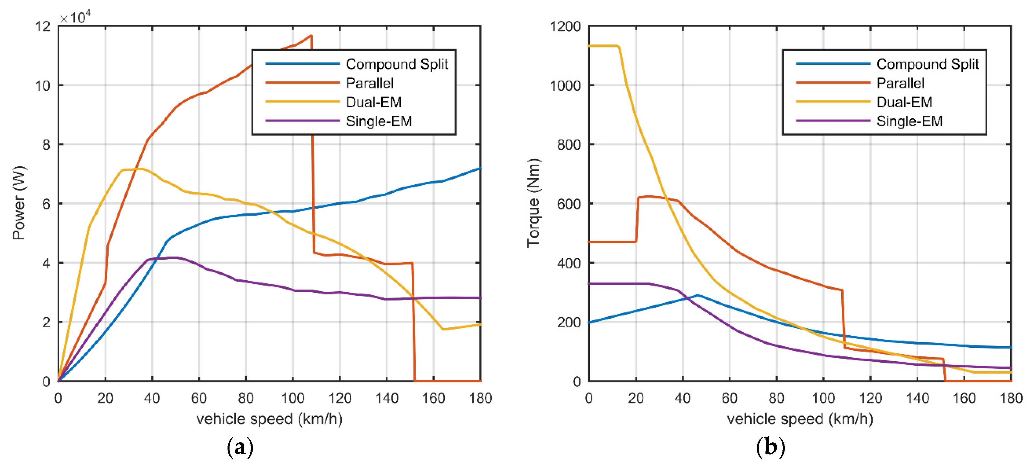
According to the kinematic relationship, the driving capacity of the multi-mode configuration shown in Figure 7d can be calculated. The maximum output torque and power for different modes are shown in Figure 8. Benefiting from the decoupling characteristic of power-split, the compound split mode can cover a wide vehicle speed range, while the parallel mode is limited by the engine maximum speed. However, in the parallel mode more torque can be output compared with the compound split mode at the same vehicle speed, which is powerful especially for climbing and accelerating. In some severe driving conditions, the parallel mode can make up the insufficiency of the compound split, which will be demonstrated in Section 4. Dual-EM mode can be considered as the enhanced electric drive version of the single-EM mode.
The multi-mode configuration increases the difficulty in the mechanical design and also introduces the problem of mode shift. Whether the modified scheme improves the fuel economy remarkably should be verified in simulation by a proper control strategy.

3. ECMS-Based Simulation

A model-based control strategy framework is inherently more flexible for different powertrain configurations than heuristics strategies and, at the same time, they can fully exploit the potential fuel economy.
Assuming the knowledge of the entire driving cycle is known previously, the global optimal control trajectory can be solved by dynamic programming (DP). The computing burden is the well-known Achilles heel, especially with the increasing number of variables, e.g., operating modes and control variables. On the other hand, instantaneous minimization methods find the local optimal solution at each time step of the optimization horizon. If the instantaneous cost function is reasonably defined, the result is close to the global optimum. The representative ECMS concept is originally from the equivalent relationship between electric energy and fossil energy assuming the SoC (state of charge) balancing over the entire driving cycle. This optimization can be effectively performed offline when the drive cycle is known and then executed online with the adaptive costs associated to the state variables [15,21]. The strategies DP, PMP, and ECMS are compared in previous research [22,23] and the theoretical relationship between the ECMS objective function and the PMP Hamilton-Jacobi-Bellman equation are also explained in [14,24,25]. ECMS is the only implementable in real-time and the equivalence with PMP and DP can tune ECMS more effectively.
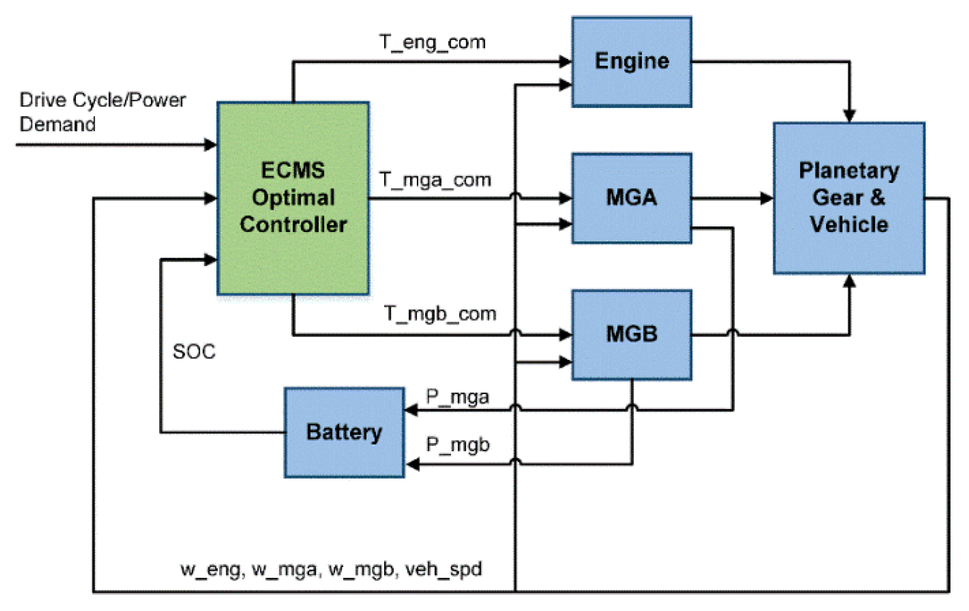
The ECMS is implemented in this paper as the core in the simulation framework for alternative four-shaft ECVT configurations as shown in Figure 9.
The equivalent fuel consumption, which is the objective function of ECMS, is:
m ˙ t o t a l = m ˙ f u e l + S C e n g f ( SoC ) E f f P b a t t = η e n g P e n g + s η k e l e P b a t t
where m ˙ t o t a l is the instantaneous equivalent fuel consumption; the engine operating along BSFC (Brake Specific Fuel Consumption) curve that has a near-linear relationship between fuel consumption m ˙ f u e l and engine power P e n g with a constant η e n g . SoC weighting factor f ( SoC ) can adapt along with SoC derivation from the target value. The equivalence factor S C e n g has a physical meaning between electric power and engine fuel consumption conversion, which is dependent on the driving cycle. s is the combination factor of S C e n g and f ( SoC ) , when the current SoC is less than SoC L , s encourages the powertrain to use the engine to recharge the battery, and vice versa, when the SoC is higher than SoCH, s encourages the powertrain to work as the EV to decrease fuel consumption. The electric system contains electric machines, inverters, and battery. The power flows in the electric system is calculated as follows:
P e l e c = T MGA w MGA η MGA K MGA + T MGB w MGB η MGB K MGB P b a t t = P e l e c η e l e c K e l e c
K i = { 1 , T i w i > 0 1 ,   T i w i < 0   f o r   i = { MGA , MGB }
K e l e c = { 1 , P b a t t > 0 1 ,   P b a t t < 0
where P e l e c is the electric power applied to both electric machines and P b a t t is the power of battery storage system. P e l e c and P b a t t are positive while the electric system outputs power to the mechanical system; in reverse when the power is negative. η MGA , η MGB , η e l e c are MGA, MGB, and electrical transferring path efficiency, respectively, and K i , K e l e c take the value of 1 when generating and −1 while motoring.
The state variables and control variables should be between the maximum and minimum limits of the corresponding components.
The state constraints are given by:
w e , min < w e < w e , max w MGA , min < w MGA < w MGA , max w MGB , min < w MGB < w MGB , max SoC min < SoC < SoC max
The control variable constraints are given by:
T e , min < T e < T e , max ( w e ) T MGA , min ( w MGA ) < T M G A < T MGA , max ( w MGA ) T MGB , min ( w MGB ) < T M G B < T MGB , max ( w MGB ) V c e l l , min < V c e l l < V c e l l , max I c e l l , min < I c e l l < I c e l l , max
where ω ( · ) , T ( · ) denote the rotation speed and torque, respectively, and the subscript indicates the component and maximum/minimum. [ V c e l l , min , V c e l l , max ] , [ I c e l l , min , I c e l l , max ] , [ SoC min , SoC max ] are the limiting values of the voltage, current, and state of charge of the battery system.
With discrete output speed and power demand, the iteration process over the feasible sets of engine operating torque and speed can yield a Pareto set of engine fuel consumption and corresponding battery power. Such Pareto-like curves formulate a look-up map with vehicle speed and power demand as input variables responding to different operating modes separately.
The simulation is based on a mid-sized sedan with two electric machines, an internal combustion engine, the proposed transmission, and a high-voltage battery system with the control strategy. The specifications are given in Table 1.
A static battery model, the equivalent circuit model, is used to calculate the state of charge. The equations are shown below:
I b a t t = V O C V O C 2 4 R P b a t t 2 R
V = V O C I b a t t R
SoC = V O C V O C 2 4 R P b a t t 2 R C b a t t
where R is the resistance of battery cell, P b a t t is the battery power, V O C is the open circuit voltage, and C b a t t is the capacity of battery.
Battery transients are neglected in the model. Two electric machines that can both work as motor and generator are built with the efficiency maps and maximum/minimum torque constraints referenced from the 2010 Prius specification. A fixed inverter efficiency of 92% is integrated in the efficiency map. Additionally, we employ the 1.8 L Atkinson cycle engine from the 2010 Prius with a fuel consumption map with respect to engine torque and speed. A set of space state matrices are already generated from Section 2. Mode shifting loss is not modeled in this quasi-steady approach.

4. Results

As described in Section 2.3.2, benefiting from the two brakes of the 2-PG configuration in Figure 7d, the four-shaft ECVT gains four operating modes. Without B1/B2 engagement, the transmission plays the role as an ECVT and the combined power flows in compound split mode. With only B1 engagement, in the hybrid mode, the vehicle runs as a parallel or compound power-split HEV, and in the electric drive mode when engine idling the vehicle is driven by the single EM. With only B2 engagement, when the engine is locked, the vehicle can be driven by both EMs and there is one control degree of freedom. When the transmission works as a single reduction gear set with a fixed gear ratio, the powertrain is the typical parallel configuration and the main benefit is the low cost cutting down one set of electric machine. This configuration is picked as the candidate to compare the fuel consumption. The states of brakes and corresponding modes are summarized in Table 2.
The configurations in Figure 7a,b can be consdiered as a subset of (d), with fewer operating modes and fewer brakes. The trade-off between complexity and fuel saving capacity need to be investigated in order to conduct the configuration design. Using the ECMS framework as a unified control strategy, three configurations are validated.

4.1. Multi-Mode Configuration with Two Brakes

4.1.1. New European Driving Cycle (NEDC) Drive Cycle Simulation and Performance

In each simulation time step, the optimal mode is decided by comparing the instantaneous equivalent fuel consumption. It is clear that, at the beginning of the New European Driving Cycle (NEDC) drive cycle where vehicle speed is low, more electric drive modes are selected as the driving mode also regenerates the braking power. As the SoC declines after the first two low-speed phases, the engine starts to satisfy the power demand from both the wheel and battery systems. The parallel mode and compound mode both participate in driving. In the last high-speed phase, a more compound split mode is chosen as the drive mode as the engine can work in the high-efficiency area. These results can be analyzed from Figure 10a and the SoC trajectory is balanced around 0.69.
Figure 10b shows the engine operation points over the entire drive cycle. Figure 10c,d show the EMA and EMB torque and speed on the efficiency maps, respectively. The fuel economy is 54.23 MPG. Further comparison with other two configurations are based on this common multiple configuration.
In order to reduce the undesired mode shifts where the selected mode cannot last as long as more than three times of simulation steps, a remedy in the objective function is added to penalize the quick shift.

4.1.2. Urban Dynamometer Driving Schedule (UDDS) Drive Cycle Simulation and Performance

Compared with the NEDC driving cycle, UDDS contains more deviation of vehicle speed and dynamic characteristics, which are close to real driving conditions and raises severe power demand. Figure 11 shows the simulation results over the UDDS driving cycle, where SoC trajectory is balanced around 0.66 and the fuel economy is 45.52 MPG. Obviously, more modes with single EM are selected, especially while regenerative braking. The EMB takes the role to apply the most braking torque and also as a traction motor in dual-EM mode with EMA.

4.2 Simplified Configuration I: Power-Split Plus Parallel Mode Configuration

4.2.1. NEDC Drive Cycle Simulation and Performance

Removing the brake B2 on the ICE node, the simplified configuration can keep both the power-split and parallel modes. The only electric drive mode is the single EM mode. The fuel consumption increases a bit at 53.58 MPG. Figure 12a indicates that this configuration can effectively select the proper drive mode as an all-mode configuration. Nevertheless the main difference of fuel economy compared with the all-mode configuration is resulted from the loss of electric efficiency. For the all-mode configuration, the total efficiency of regenerative braking, namely the effective electric power recaptured from the wheel, is 80.76%. While, for the simplified case here, the efficiency is 60.37%. The drawback is the drag loss of the engine in single EM mode and the potential damage.

4.2.2. UDDS Drive Cycle Simulation and Performance

From Section 4.1.2, the simulation results showed the lean on the single EM mode, especially while regenerative braking. Whereas Figure 13 shows the simulation results over the UDDS driving cycle, where SoC trajectory is balanced around 0.67 and the fuel economy is 42.12 MPG. The parallel mode is selected to substitute the dual-EM mode while driving, which leads to more gasoline fuel consumption. Compared with the all-mode configuration, the fuel economy has been dragged down.

4.3 Simplified Configuration II: Power-Split Mode Only Configuration

The simplified configuration with compound split mode and dual-EM mode is simulated here. Without the parallel mode, only the hybrid mode plays the important role in driving and SoC regulation. Finally, the SoC is balanced around 0.69. The engine operation points are kept on the BSFC curve and the final MPG is 51.40. The battery trajectory and mode utilization is shown in Figure 14a. The engine and electric machines worked in the sweet spot shown in Figure 14b–d.
As analyzed in Section 2, the kinematic relationship of the multi-mode configuration ensures the driving capacity of the parallel mode and the wide velocity range of the compound power-split mode. Thus, in the UDDS drive cycle the parallel mode is the necessary selection for the configuration. This simplified configuration is not considered as a candidate for severe driving conditions.

4.4 Simplified Configuration III: Parallel Mode Only Configuration

4.4.1. NEDC Drive Cycle Simulation A Performance

The configuration employing the parallel mode plus single-EM mode is also simulated as a contrast. The SoC is balanced around 0.6, which is lower than the first two configurations. As a result, after the single-EM drive mode, the engine has to be started to keep the SoC changing in the regulation range. Additionally, in the high-speed phase, with the vehicle speed and power demand increasing, the parallel mode cannot work in the engine sweet spot because of the single fixed gear ratio. It is obvious in Figure 15b that the engine efficiency deteriorates in the high speed area. As the simplified configuration only needs EMB to coordinate with the engine, the corresponding operating points of the EMB are plotted in Figure 15c. Therefore, the fuel consumption is 50.07 MPG, which is higher than the other configurations.

4.4.2. UDDS Drive Cycle Simulation and Performance

Figure 16 shows the simulation results over the UDDS driving cycle, where the SoC trajectory is balanced around 0.57 and the fuel economy is 41.47 MPG. Obviously, more modes with single EM are selected, especially while regenerative braking. Without the compound power-split mode, the engine has to operate more frequently to keep the SoC and fulfill the driving demand. Similarly, as over the NEDC driving cycle, the engine cannot work along the most efficient curve, which results in added fuel consumption, as shown in Figure 16b.

5. Discussion

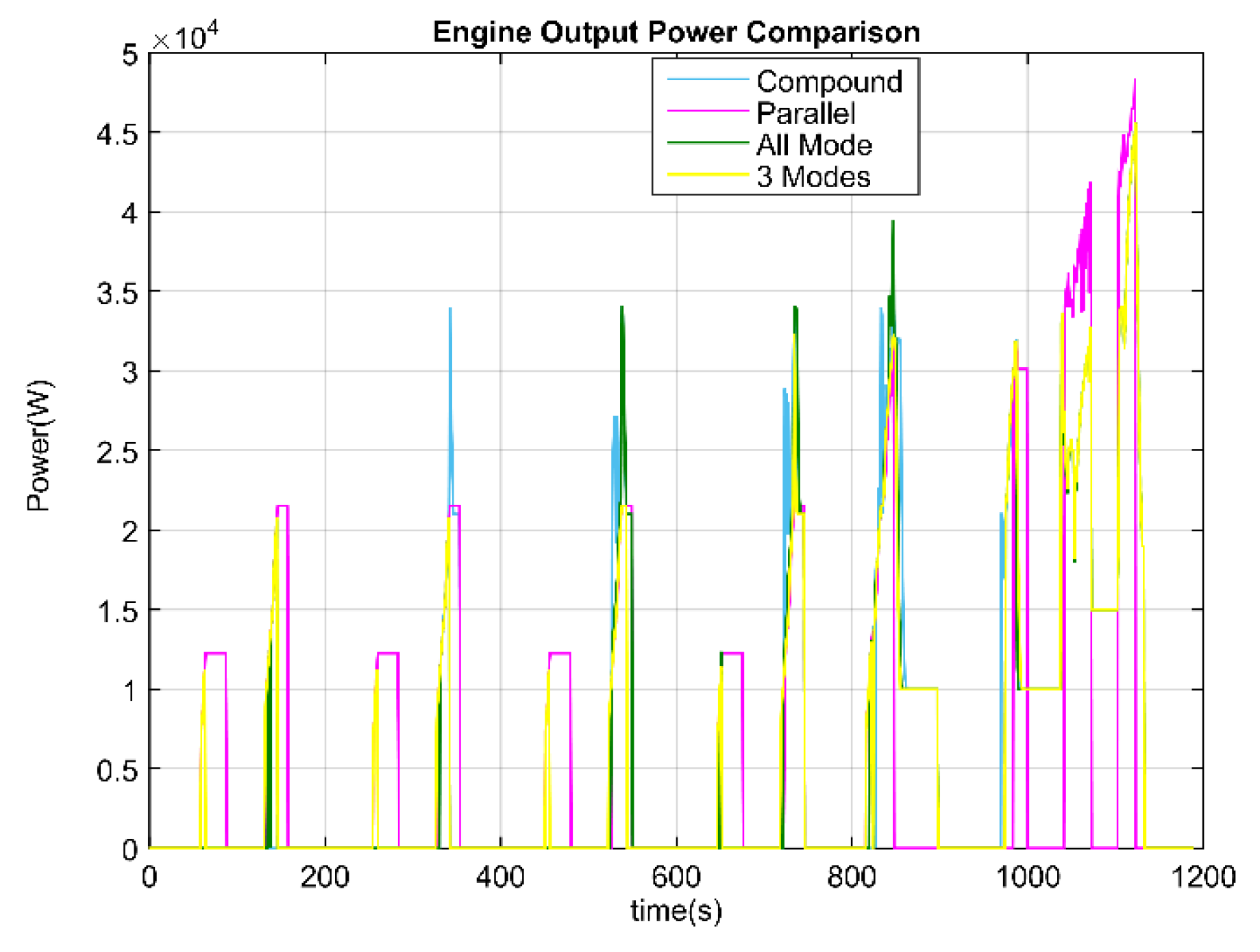
For the hybrid electric vehicle with a charge-sustaining control strategy, the key point of fuel saving are the engine operating points. The frequent start-stop and low efficiency operating increase the fuel consumption, which is the reason for the configuration with the parallel mode as the only hybrid mode. The engine output power during the NEDC drive cycle for all four configurations are plotted in Figure 17. The simplified Configuration I is always in the same range of engine operating points as the all-mode configuration, except with some extra charging condition at low speed.
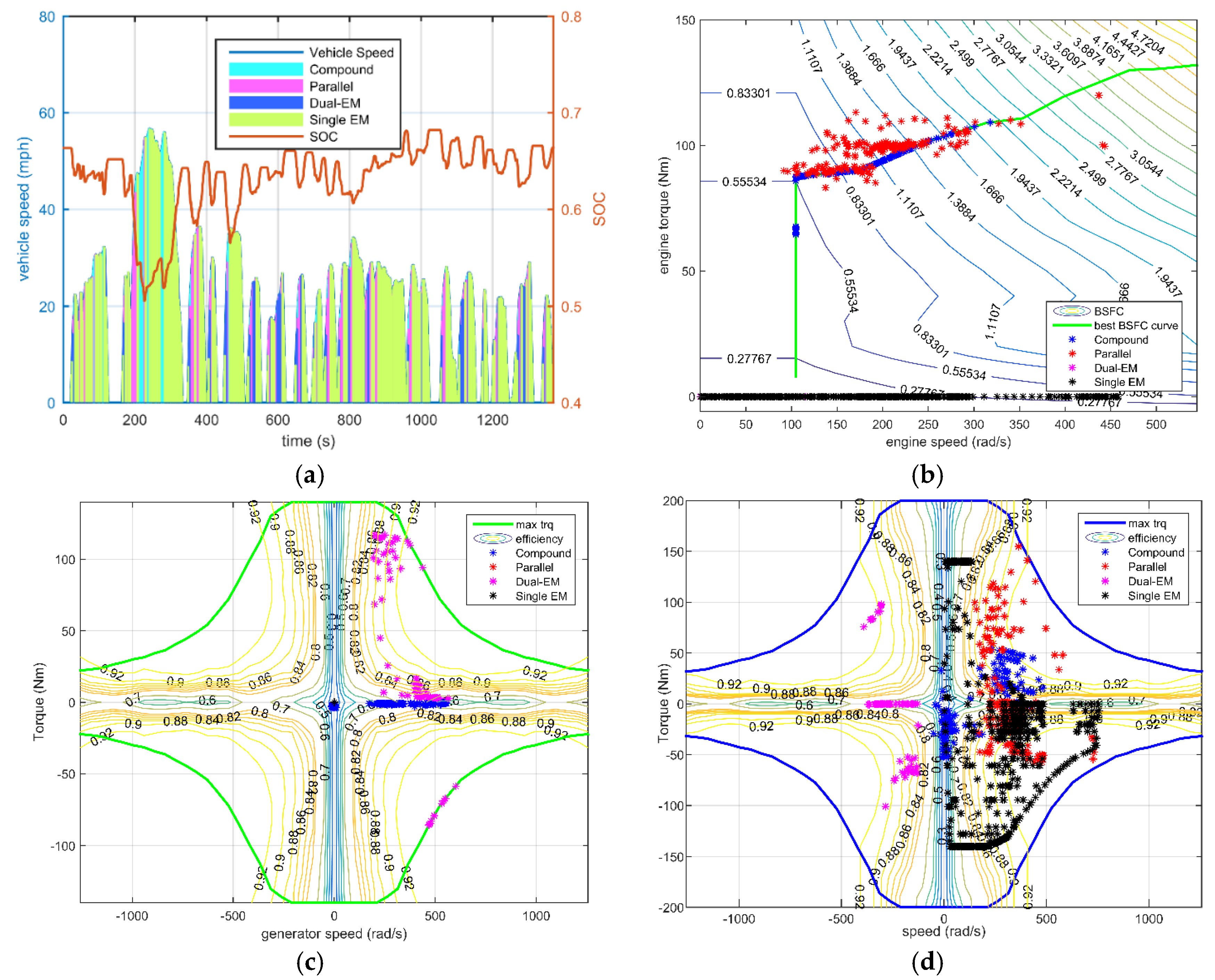
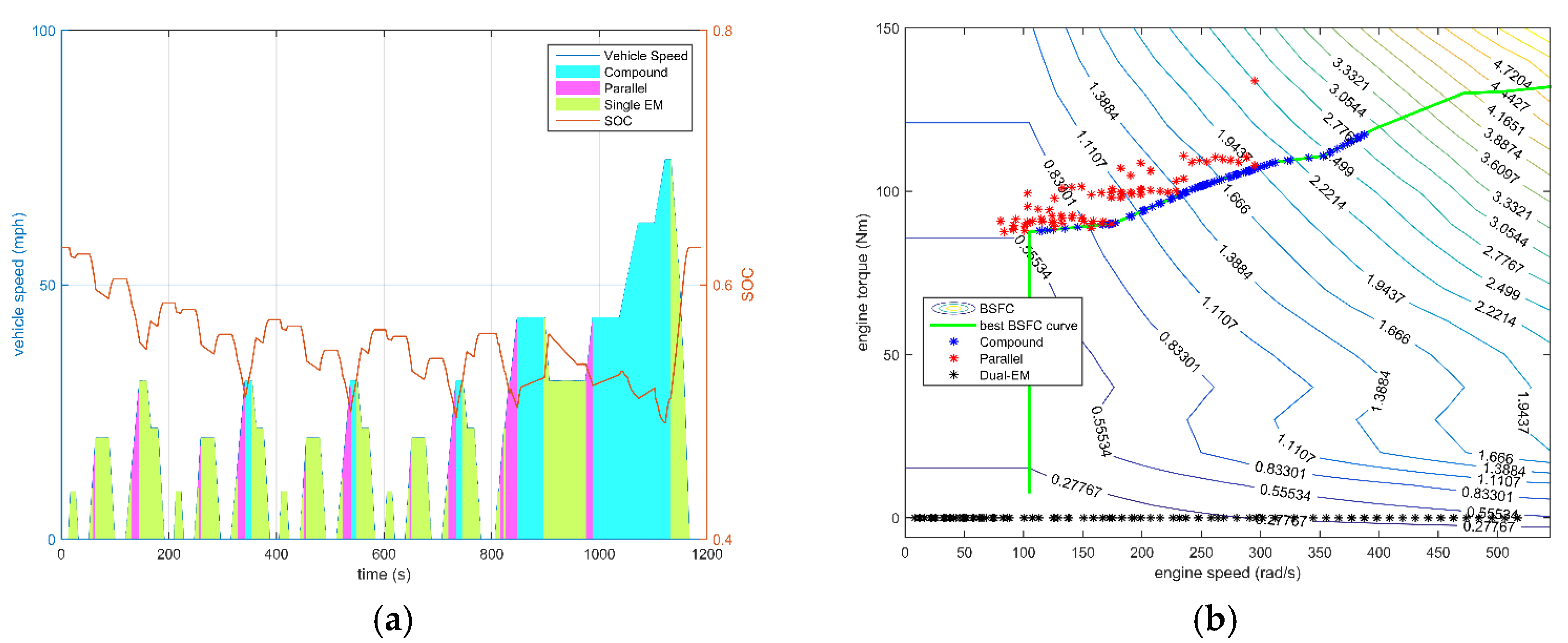
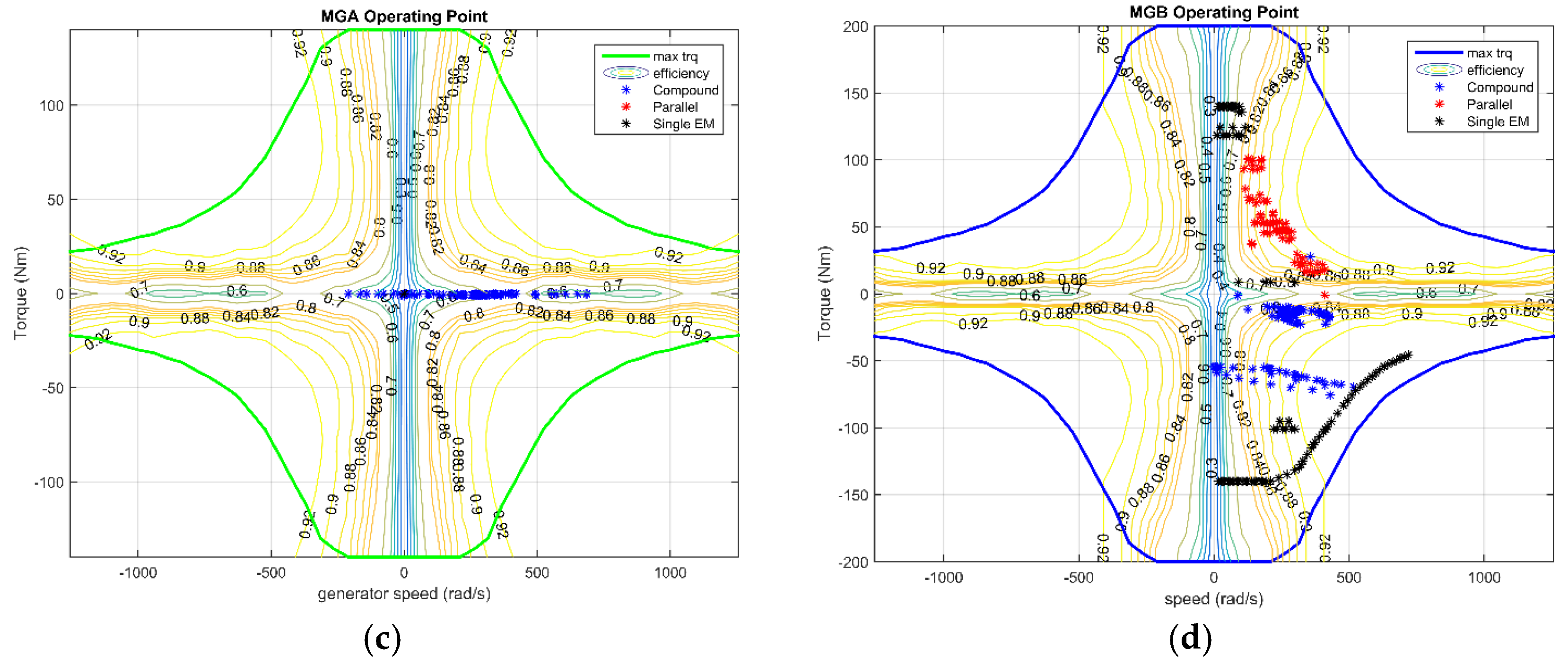
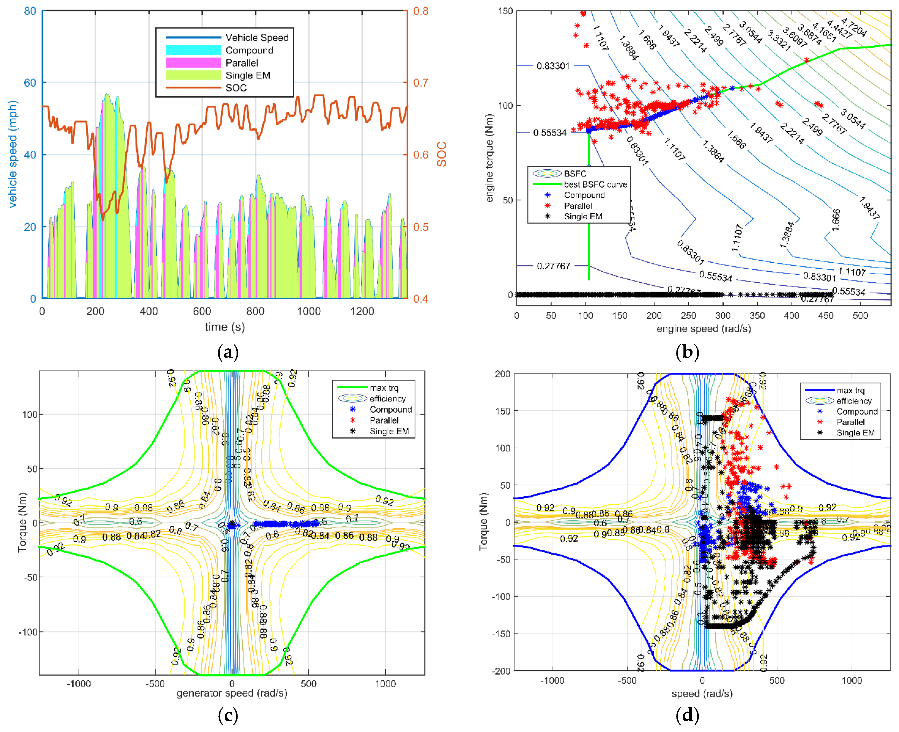
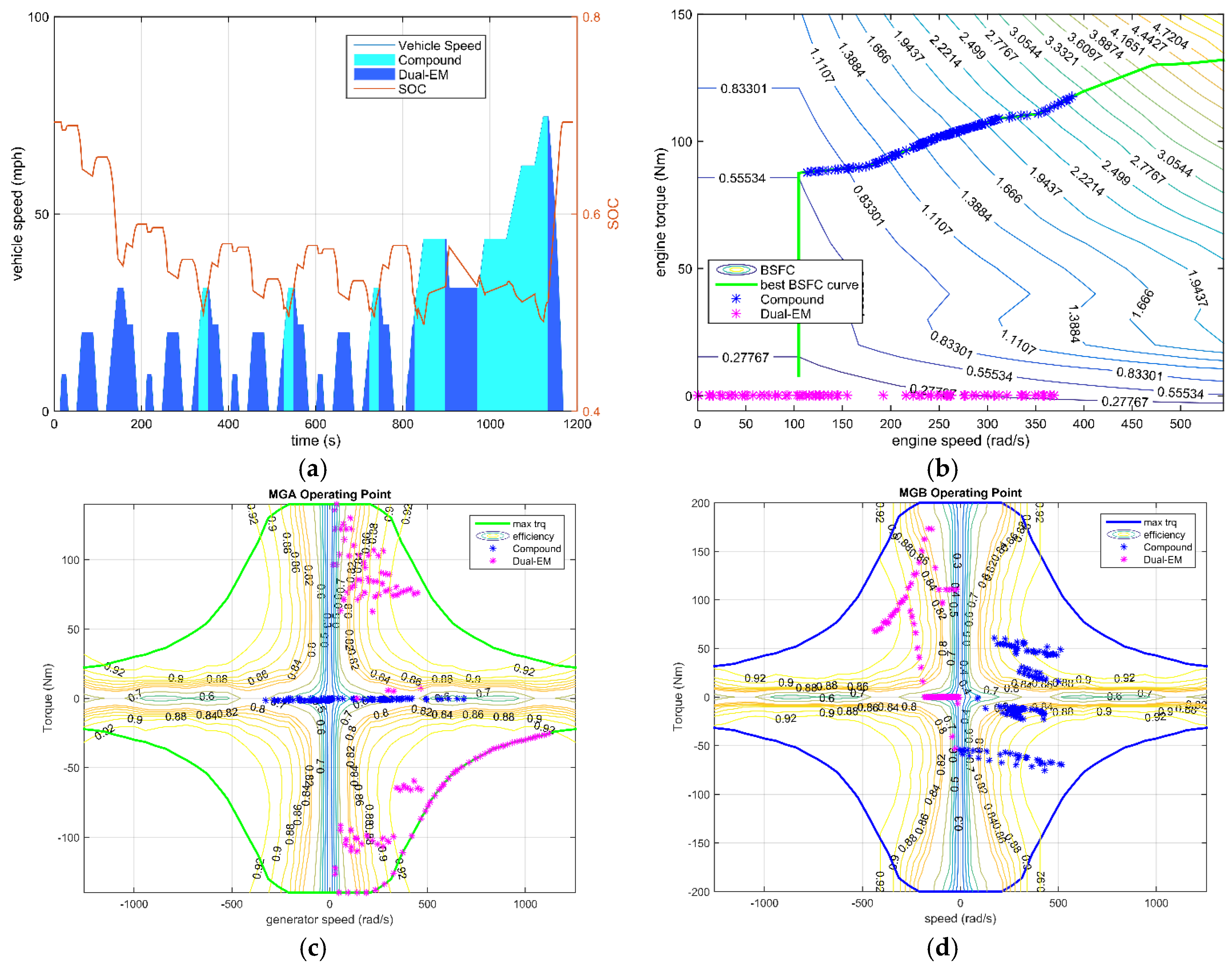
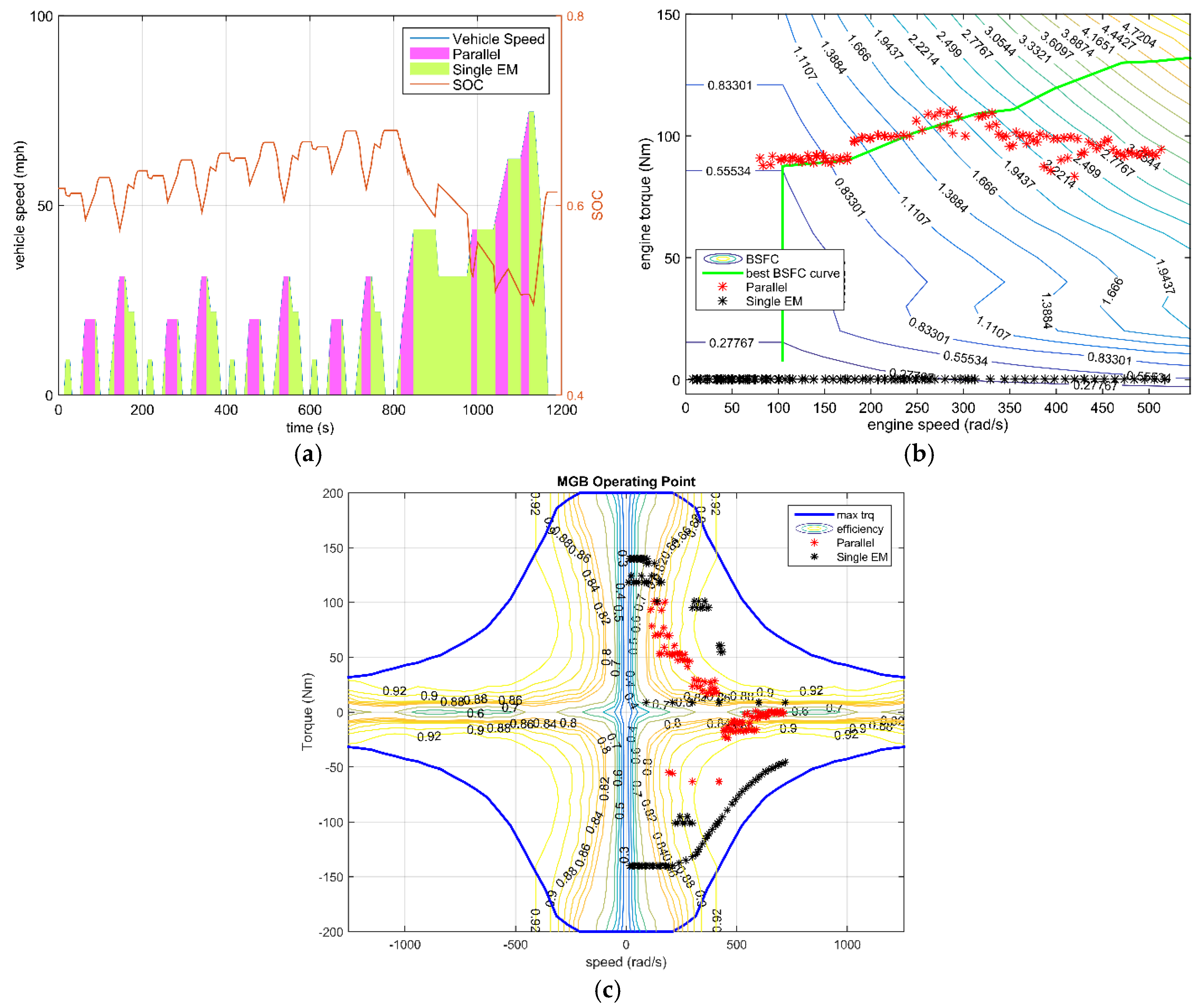
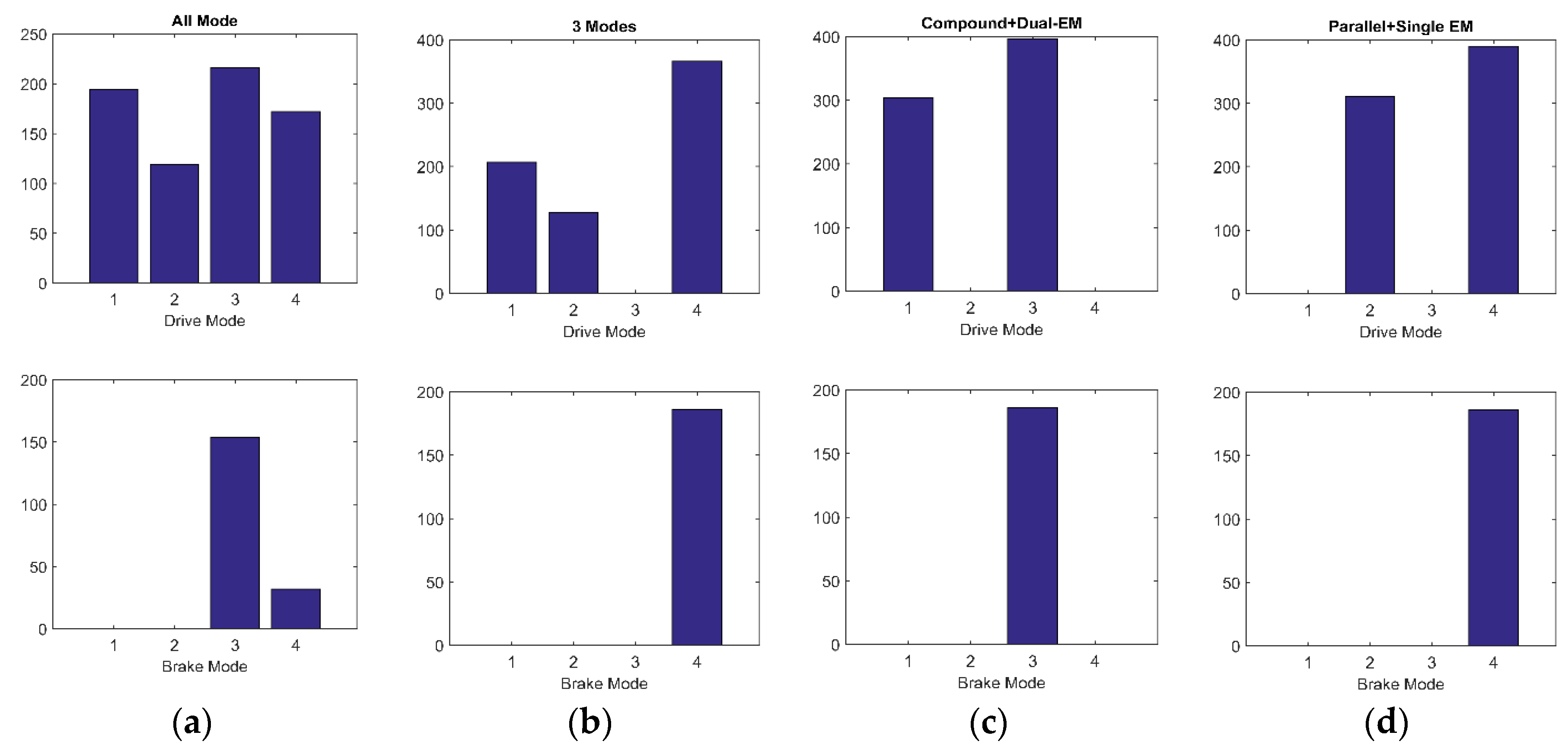
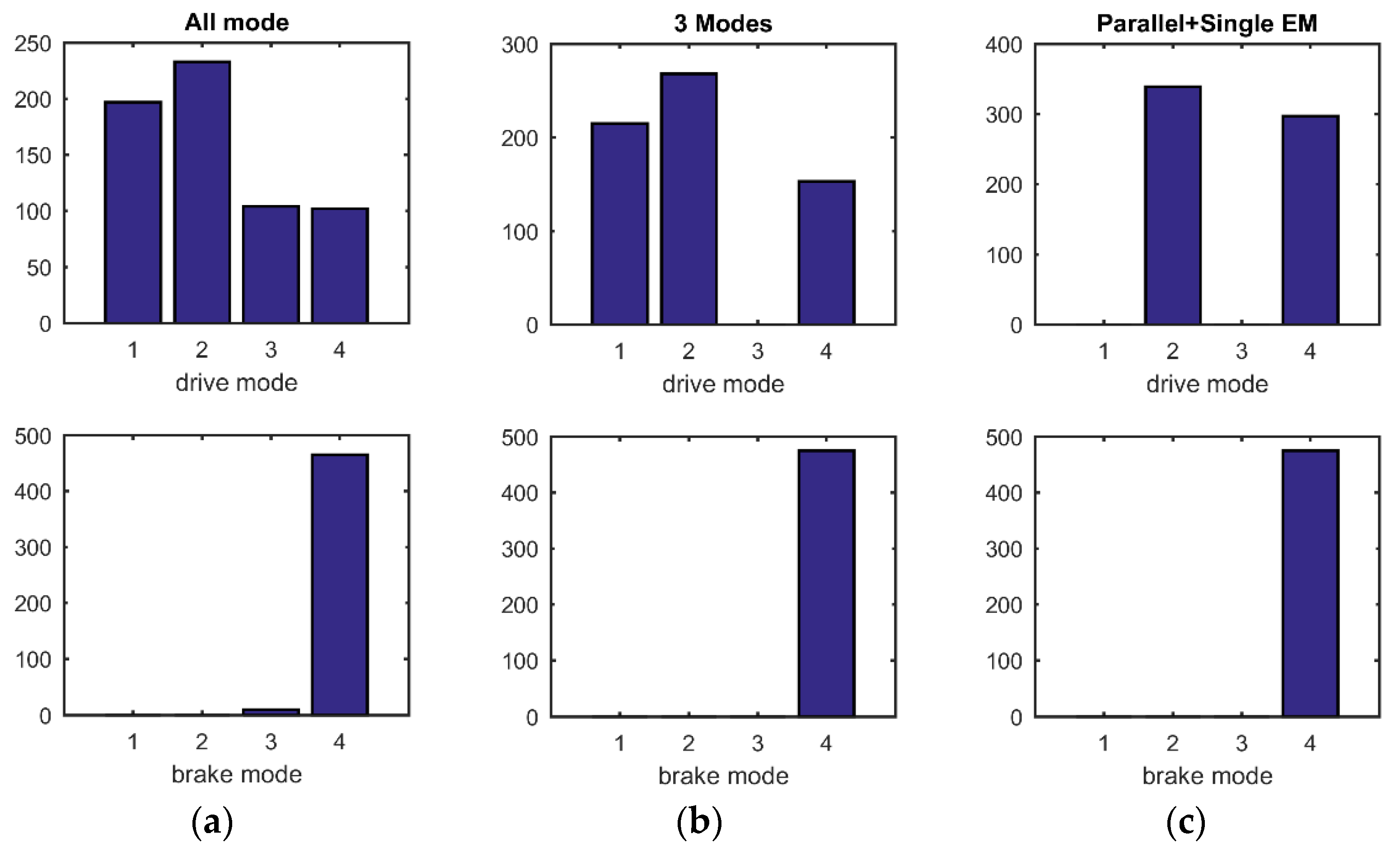
Additionally, the frequency of different modes of utilization can be obtained from Figure 18 and Figure 19. As the electrical efficiency is relatively high, the difference in loss between two electric drive modes and the single electric drive mode (either dual-EM or single-EM) contributes little to the final fuel consumption, but influences the regenerative braking energy. In the all-mode configuration, compound split is selected more frequently than the parallel mode over the NEDC driving cycle, therefore the simplified Configuration II performed a bit better than Configuration III. While considering the maximum output torque capability the parallel mode is advantageous, considering the requirements of driving performance. To fulfill the driving demand, the simplified Configuration III is the winner. Generally, considering both the fuel economy and driving capacity, the simplified Configuration I with three operating modes is obviously a better design.
From the viewpoint of exploiting the potential, both in fuel economy and driving performance, the powertrain needs both power-split mode and parallel mode. The fuel consumption is summarized in Table 3 and Table 4. Additionally, these two hybrid modes should be coordinated with the optimal control strategy. Nevertheless the trade-off between cost increased due to complicated configuration and fuel economy should be considered again by the manufacture.

6. Conclusions

The proposed methodology examines the feasibility and driving capacity during the first steps of design and development of four-shaft ECVT configuration from the conventional ATs. A set of novel four-shaft hybrid transmissions that couple the power from EMs and ICE have been derived from the 2-PG configuration of the Ravigneaux AT. Such architectures have both hybrid mode and electric drive mode and can be optimally controlled by switching among different operating modes in order to optimize the energy utilization efficiency.
In compound split mode, the transmission with two DOFs(Degree Of Freedom) decouples the engine operation from the vehicle load. The simulation results indicate again that the power-split mode has obvious advantage over the parallel mode in terms of fuel economy. Dual-EM mode and single-EM mode can complement each other with respect to the efficiency, especially during regenerative braking. Except for the concern of fuel consumption, the driving performance is also an important index. Parallel mode and dual-EM mode are inherently advantageous. Taking the fuel consumption and cost into consideration, a simplified configuration with only B1 is more suitable.
Mode shifting loss caused by friction and idling are not modeled in this study, which is especially significant in drivability. Thus, further work will include the implementation in real driving conditions, as well as improved drivability constraints, e.g., clutch/brakes engagement/disengagement. Additionally, more theoretical research on this multi-objective problem needs to be investigated to integrate the configuration complexity into powertrain life cost, as well as fuel consumption.
In addition, this study focuses on the configuration design and screening, the gear ratios and power component sizing are fixed at the beginning of the design process. While the parameter-matching influences the system efficiency, another group of parameters may obtain better fuel consumption and may affect the optimal architecture selection. Thus, the configuration optimization, considering the parametric design at the same time, remains to be investigated.

Acknowledgments

The research work in this paper is supported by a grant from US-China Clean Energy Research Collaboration: Collaboration on cuttingedge technology development of electric vehicle (Program of International S&T Cooperation) (2010DFA72760).

Author Contributions

Yong Zhang and Xuerui Ma conducted the main work of the systematic process of design and simulation and also drafted the paper. Shifei Yuan checked out and revised the paper. Chengliang Yin provided insightful suggesting on the research and simulation results analysis.

Conflicts of Interest

The authors declare no conflict of interest.

References

  1. Brendan, C. Comparative analysis of single and combined hybrid electrically variable transmission operating modes. Sae Trans. 2005. [Google Scholar] [CrossRef]
  2. Zhang, X.; Chiao-Ting, L.I.; Dongsuk, K.; Peng, H. Prius+ and Volt-: Configuration analysis of power-split hybrid vehicles with a single planetary gear. IEEE Trans. Veh. Technol. 2012, 61, 3544–3552. [Google Scholar] [CrossRef]
  3. Meisel, J. An Analytic Foundation for the Toyota Prius THS-II Powertrain with a Comparison to a Strong Parallel Hybrid-Electric Powertrain; SAE Technical Paper 2006-01-0666; SAE International: Warrendale, PA, USA, 2006. [Google Scholar]
  4. Liu, J. Modeling, Configuration and Control Optimization of Power-Split Hybrid Vehicles. Ph.D. Thesis, The University of Michigan, Ann Arbor, MI, USA, 2007. [Google Scholar]
  5. Holmes, A.G.; Schmidt, M.R. Hybrid Electric Powertrain Including a Two-Mode Electrically Variable Transmission U.S. Patent No. 6,478,705, 2002.
  6. Hendrickson, J.; Holmes, A.; Freiman, D. General Motors Front Wheel Drive Two-Mode Hybrid Transmission; SAE Technical Paper: 2009-01-0508; SAE International: Warrendale, PA, USA, 2009. [Google Scholar]
  7. Mashadi, B.; Emadi, S.A.M. Dual-mode power-split transmission for hybrid electric vehicles. IEEE Trans. Veh. Technol. 2010, 59, 3223–3232. [Google Scholar] [CrossRef]
  8. Miller, M.A.; Holmes, A.G.; Conlon, B.M.; Savagian, P.J. The GM “Voltec” 4ET50 multi-mode electric transaxle. Sae Int. J. Eng. 2011, 4, 1102–1114. [Google Scholar] [CrossRef]
  9. Ma, X.; Zhang, Y.; Yin, C. Kinematic Study and Mode Analysis of a New 2-Mode Hybrid Transmission; Springer: Berlin, Germany, 2013; pp. 309–318. [Google Scholar]
  10. Zhu, F.C.L.; Yin, C. Design and analysis of a novel multimode transmission for a HEV using a single electric machine. IEEE Trans. Veh. Technol. 2013, 62, 1097–1110. [Google Scholar] [CrossRef]
  11. Barhoumi, T.; Kum, D. Automated schematic design of power-split hybrid vehicles with a single planetary gear. In Proceedings of the ASME 2014 Dynamic Systems and Control Conference, San Antonio, TX, USA, 22–24 October 2014.
  12. Salmasi, F.R. Control strategies for hybrid electric vehicles: Evolution, classification, comparison, and future trends. IEEE Trans. Veh. Technol. 2007, 56, 2393–2404. [Google Scholar] [CrossRef]
  13. Liu, J.; Peng, H. Control optimization for a power-split hybrid vehicle. In Proceedings of the American Control Conference, Minneapolis, MN, USA, 14–16 June 2006.
  14. Serrao, L.; Onori, S.; Rizzoni, G. ECMS as a Realization of Pontryagin’s Minimum Principle for HEV Control, Proceedings of the 2009 conference on American Control Conference, 2009; IEEE Press, 2009; pp. 3964–3969.
  15. Musardo, C.; Rizzoni, G.; Guezennec, Y.; Staccia, B. A-ECMS: An adaptive algorithm for hybrid electric vehicle energy management. Eur. J.Control 2005, 11, 509–524. [Google Scholar] [CrossRef]
  16. Xiaowu, Z.; Huei, P.; Jing, S. A near-optimal power management strategy for rapid component sizing of multimode power split hybrid vehicles. IEEE Trans. Control Syst. Technol. 2015, 23, 609–618. [Google Scholar] [CrossRef]
  17. Benford, H.; Leising, M. The LEVER Analogy: A New Tool in Transmission Analysis; SAE Technical Paper 810102; SAE International: Warrendale, PA, USA, 1981. [Google Scholar]
  18. Wang, C.; Zhao, Z.; Zhang, T.; Dai, X.; Yuan, X. Development of a Compact Compound Power-Split Hybrid Transmission Based on Altered Ravigneaux Gear Set; SAE Technical Paper 2014-01-1793; SAE International: Warrendale, PA, USA, 2014. [Google Scholar]
  19. Koprubasi, K.; Westervelt, E.; Rizzoni, G. Toward the systematic design of controllers for smooth hybrid electric vehicle mode changes. In Proceedings of the American Control Conference, New York, NY, USA, 9–13 July 2007.
  20. Schulz, M. Set values for a power-split hybrid electric vehicle through numerical optimisation. Int. J. Altern. Propuls. 2006, 1, 6–31. [Google Scholar] [CrossRef]
  21. Sciarretta, A.; Guzzella, L. Control of hybrid electric vehicles. IEEE Control Syst. 2007, 27, 60–70. [Google Scholar] [CrossRef]
  22. Serrao, L.; Onori, S.; Rizzoni, G. A comparative analysis of energy management strategies for hybrid electric vehicles. J. Dyn. Syst. Meas. Control 2011, 133, 031012. [Google Scholar] [CrossRef]
  23. Chasse, A.; Sciarretta, A. Supervisory control of hybrid powertrains: An experimental benchmark of offline optimization and online energy management. Control Eng. Pract. 2011, 19, 1253–1265. [Google Scholar] [CrossRef]
  24. Kim, N.; Rousseau, A. Sufficient conditions of optimal control based on Pontryagin’s minimum principle for use in hybrid electric vehicles. J. Automob. Eng. 2012, 226, 1160–1170. [Google Scholar] [CrossRef]
  25. Kim, N.; Cha, S.W.; Peng, H. Optimal equivalent fuel consumption for hybrid electric vehicles. IEEE Trans. Control Syst.Technol. 2012, 20, 817–825. [Google Scholar]
Figure 1. (a) Simple gear set scheme; and (b) compound gear set scheme.
Energies 09 00141 g001
Figure 2. (a) Simple gear set lever. (b) Compound gear set lever. ρ = Z R Z S , where ZR is the number of ring gear teeth, ZS is the number of sun gear teeth.
Energies 09 00141 g002
Figure 3. (a) Simpson automotive transmission configuration; and (b) combined lever diagram, where ρ 1 = Z R 1 Z S 1 , ρ 2 = Z R 2 Z S 2 .
Energies 09 00141 g003
Figure 4. (a) Ravigneaux automotive transmission configuration; (b) Combined lever diagram, where ρ 1 = Z R 1 Z S 1 , ρ 2 = Z R 2 Z S 2 .
Energies 09 00141 g004
Figure 5. (a) Feasible connections of the output shaft and speed relationship of the Simpson 2-PG; (b) Feasible connections of the output shaft and speed relationship of the Ravigneaux 2-PG.
Energies 09 00141 g005
Figure 6. A new four-shaft hybrid transmission.
Energies 09 00141 g006
Figure 7. (a) Adding a brake on the node of EMA; (b) Adding a brake on the node of ICE; (c) Adding a brake on the node of EMB; (d) Adding two brakes on both EMA and ICE.
Energies 09 00141 g007
Figure 8. (a) Maximum output power; (b) Maximum output torque.
Energies 09 00141 g008
Figure 9. Simulation framework with an ECMS optimal controller for alternative powertrain configurations.
Energies 09 00141 g009
Figure 10. (a) Battery SoC trajectory and mode selection over the NEDC drive cycle; (b) engine optimal operation points over the NEDC drive cycle; (c) EMA operating points over the NEDC drive cycle; (d) EMB operating points over the NEDC drive cycle.
Energies 09 00141 g010
Figure 11. (a) Battery SoC trajectory and mode selection over the UDDS drive cycle; (b) rngine optimal operation points over the UDDS drive cycle; (c) EMA operating points over the UDDS drive cycle; (d) EMB operating points over the UDDS drive cycle.
Energies 09 00141 g011
Figure 12. (a) Battery SOC trajectory and mode selection over the NEDC drive cycle; (b) engine optimal operation points over the NEDC drive cycle; (c) EMA operating points over the NEDC drive cycle; (d) EMB operating points over the NEDC drive cycle.
Energies 09 00141 g012aEnergies 09 00141 g012b
Figure 13. (a) Battery SoC trajectory and mode selection over the UDDS drive cycle; (b) engine optimal operation points over the UDDS drive cycle; (c) EMA operating points over the UDDS drive cycle; and (d) EMB operating points over the UDDS drive cycle.
Energies 09 00141 g013
Figure 14. (a) Battery SoC trajectory and mode selection during theNEDC drive cycle; (b) engine optimal operation points during the NEDC drive cycle; (c) EMA operating points over the NEDC drive cycle; and (d) EMB operating points over the NEDC drive cycle.
Energies 09 00141 g014
Figure 15. (a) Battery SoC trajectory and mode selection over the NEDC drive cycle; (b) engine optimal operation points over the NEDC drive cycle; and (c) EMB operating points over te NEDC drive cycle.
Energies 09 00141 g015
Figure 16. (a) Battery SoC trajectory and mode selection over the UDDS drive cycle; (b) engine optimal operation points over the UDDS drive cycle; (c) EMB operating points over the UDDS drive cycle.
Energies 09 00141 g016
Figure 17. Engine output power for four configurations over the NEDC driving cycle.
Energies 09 00141 g017
Figure 18. Frequency of mode utilization in four different configurations over the NEDC driving cycle: (a) All Mode Configuration; (b) 3 Modes Configuration; (c) Compound+Dual EM Configuration; (d) Parallel + Single EM Configuration.
Energies 09 00141 g018
Figure 19. Frequency of mode utilization in three different configurations over the UDDS driving cycle: (a) All Mode Configuration; (b) 3 Modes Configuration; (c) Parallel + Single EM Configuration.
Energies 09 00141 g019
Table 1. Vehicle Parameters.
VehicleMass (kg)1380
Frontal Area (m2)2.33
Cd0.25
Tire Radius (m)0.308
Final Drive3.905
TransmissionPG1 ratio2.35
PG2 ratio3.175
EngineMax speed (rpm)5200
Max torque (Nm)142@4000 rpm
Max power (kW)73
MGAMax speed (rpm)12,000
Max torque (Nm)140
Max power (kW)42
MGBMax speed (rpm)12,000
Max torque (Nm)200
Max power (kW)60
Battery (LiFePO4)Capacity (Ah)6.5
High Voltage (V)201.6
Table 2. Brakes states and corresponding modes.
ModeBrakes
B1B2
Compound Split00
Parallel10
Dual-EM01
Single EM10
Invalid11
Table 3. Fuel Consumption over the NEDC Cycle.
ConfigurationBalance SoCMPGPercentage
All Mode0.6954.230
3 Modes0.6353.58−1.21%
Compound + Dual-EM0.6951.40−5.21%
Parallel + Single EM0.6150.07−7.68%
Table 4. Fuel Consumption over UDDS Cycle.
ConfigurationBalance SoCMPGPercentage
All Mode0.6645.520
3 Modes0.6742.12−7.47%
Parallel + Single EM0.5741.37−9.12%

