
A Review of Research on Large Scale Modern Vertical Axis Wind Turbines at Uppsala University

Abstract
:
1. Introduction
- A direct driven generator is spared from losses, maintenance and costs associated with a gearbox [8].
- It has been shown that the gearbox is a critical component when it comes to wind turbine failures [9].
- A gearbox would reduce the overall efficiency.
- The overall system becomes simpler.
- The wind turbine will be able to react more rapidly to changes in the wind and the load [10].
1.1. History of VAWT
2. Fundamentals
3. 200 kW VAWT
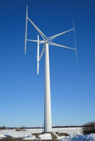
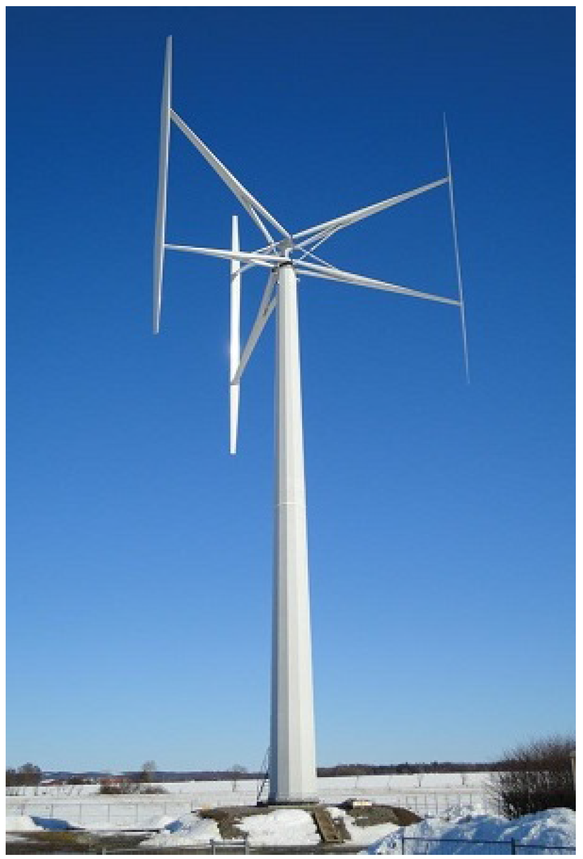
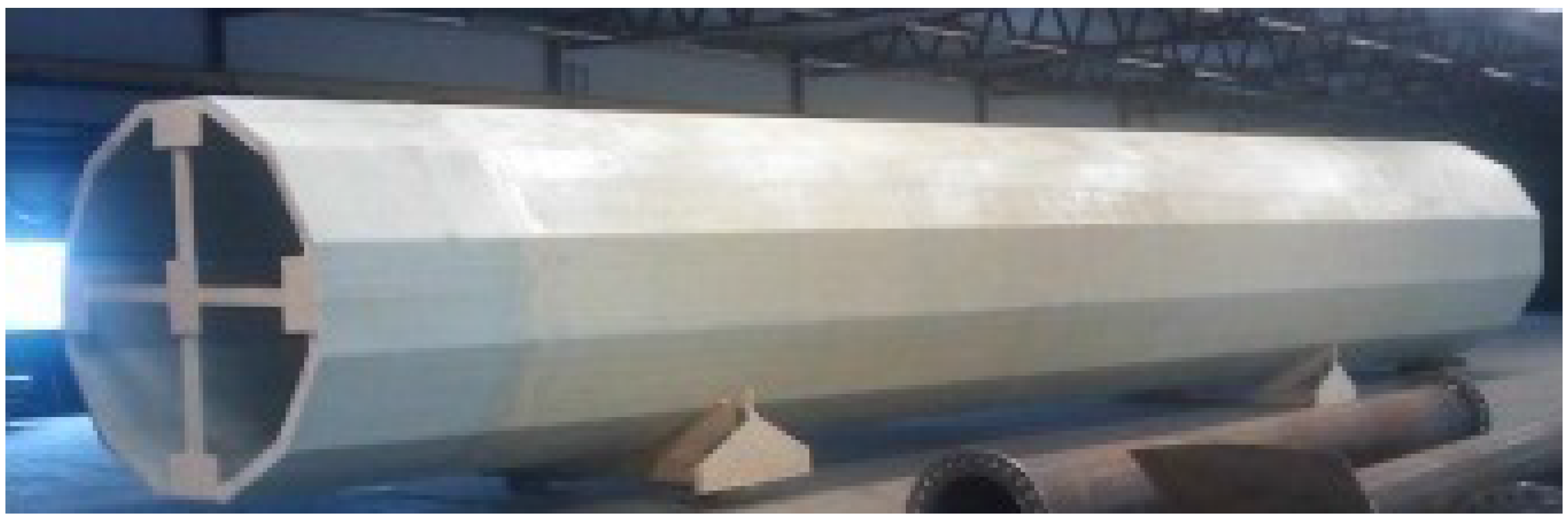
3.1. Turbine
3.2. Tower
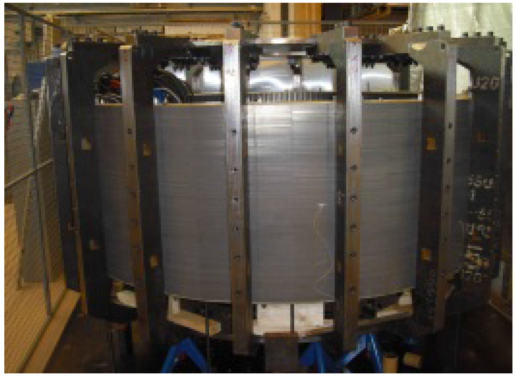
3.3. Generator
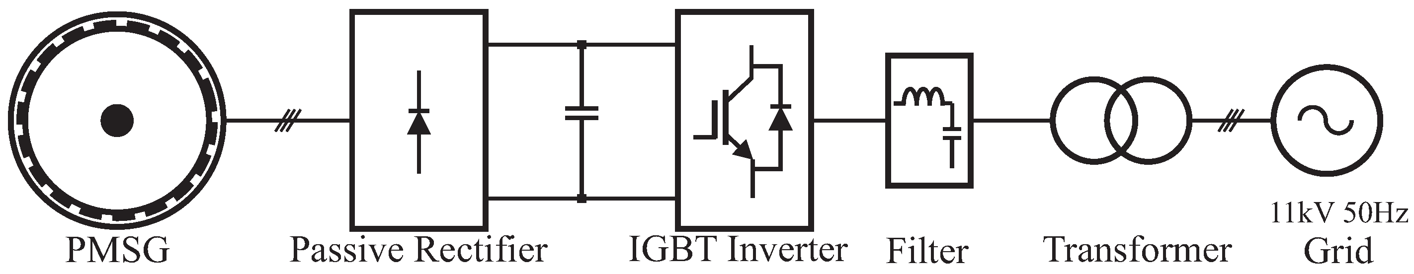
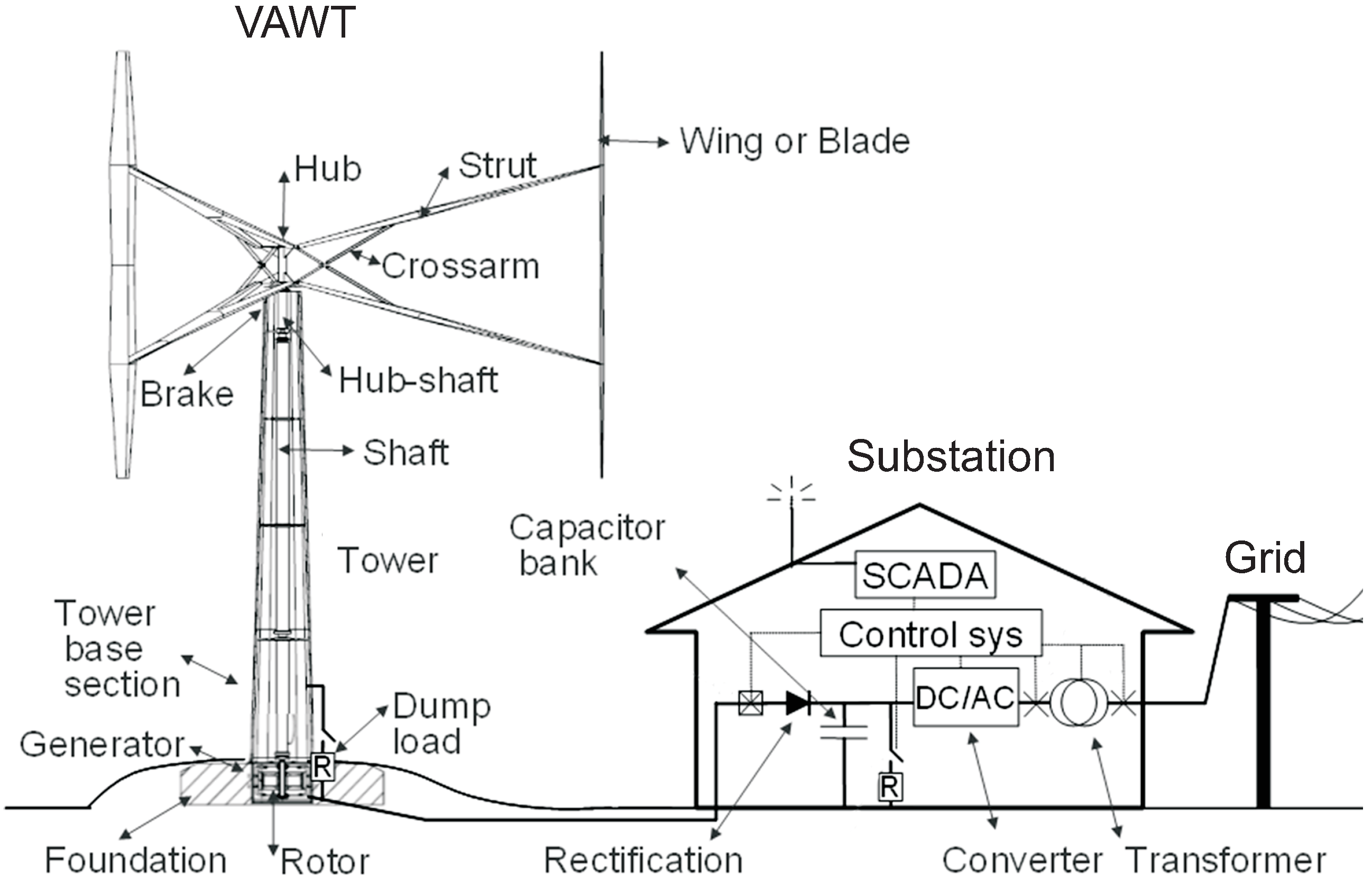
3.4. Substation and Turbine Operation
3.5. Aerodynamics
3.6. Simulations of Farm Operation
3.7. Turbine Noise
4. Marsta Research Site
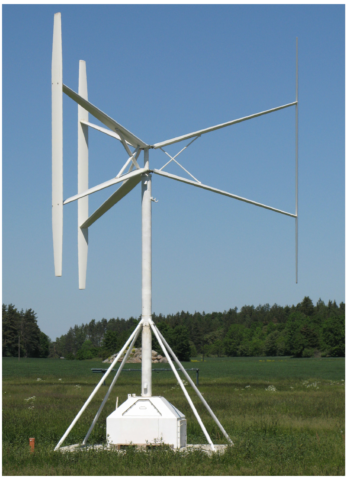
4.1. 12 kW Turbine
4.2. Generator
4.3. Control System
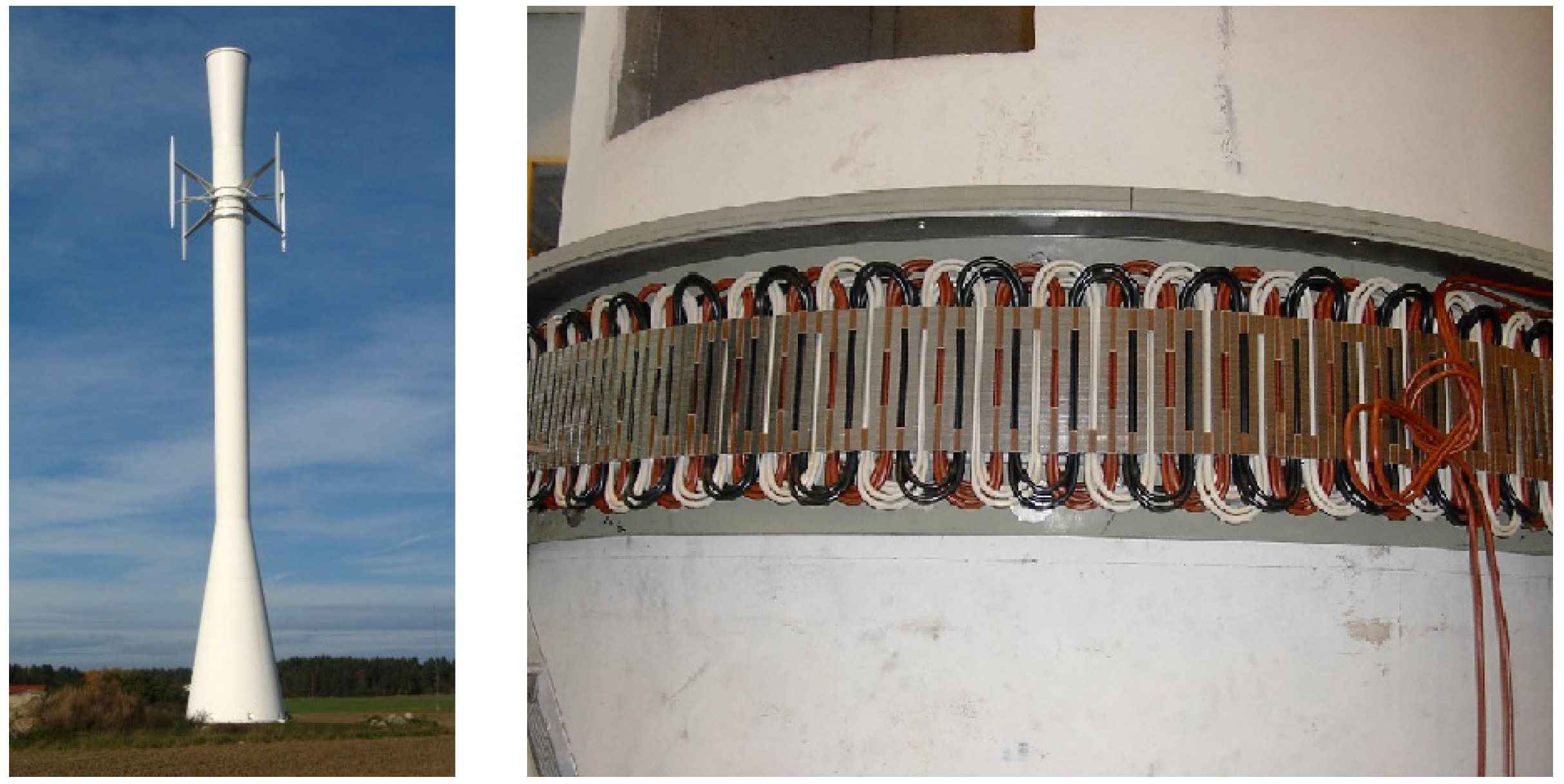
4.4. VAWT Adapted to an Existing Telecommunications Tower
5. Research on Generators for VAWTs
6. Research on Aerodynamics for Vertical Axis Turbines
7. Multi-MW
8. Conclusions
Acknowledgments
Author Contributions
Conflicts of Interest
References
- Herbert, G.J.; Iniyan, S.; Sreevalsan, E.; Rajapandian, S. A review of wind energy technologies. Renew. Sustain. Energy Rev. 2007, 11, 1117–1145. [Google Scholar] [CrossRef]
- Manwell, J.F.; McGowan, J.G.; Rogers, A.L. Wind Energy Explained: Theory, Design and Application; John Wiley & Sons: New York, NY, USA, 2010. [Google Scholar]
- Carlin, P.W.; Laxson, A.S.; Muljadi, E. The history and state of the art of variable-speed wind turbine technology. Wind Energy 2003, 6, 129–159. [Google Scholar] [CrossRef]
- Smith, D. The wind farms of the Altamont Pass area. Ann. Rev. Energy 1987, 12, 145–183. [Google Scholar] [CrossRef]
- Peace, S. Wind alternatives: Why not vertical axis? Refocus 2003, 4, 30–33. [Google Scholar]
- Paulsen, U.S.; Madsen, H.A.; Hattel, J.H.; Baran, I.; Nielsen, P.H. Design optimization of a 5 MW floating offshore vertical-axis wind turbine. Energy Procedia 2013, 35, 22–32. [Google Scholar] [CrossRef] [Green Version]
- Paulsen, U.S.; Madsen, H.A.; Kragh, K.A.; Nielsen, P.H.; Baran, I.; Hattel, J.; Ritchie, E.; Leban, K.; Svendsen, H.; Berthelsen, P.A. DeepWind-from idea to 5 MW concept. Energy Procedia 2014, 53, 23–33. [Google Scholar] [CrossRef] [Green Version]
- Jöckel, S. Gearless wind energy converters with permanent magnet generators-an option for the future? In Proceedings of the European Union Wind Energy Conference and Exhibition, Göteborg, Sweden, 20–24 May 1996; pp. 414–417.
- Ribrant, J.; Bertling, L. Survey of failures in wind power systems with focus on Swedish wind power plants during 1997–2005. In Proceedings of the Power Engineering Society General Meeting, Tampa, FL, USA, 24–28 June 2007; pp. 1–8.
- Chen, J.Y.; Nayar, C.; Xu, L. Design and FE analysis of an outer-rotor PM generator for directly-coupled wind turbine applications. In Proceedings of the Thirty-Third IAS Annual Meeting Industry Applications Conference, St. Louis, MO, USA, 12–15 October 1998; Volume 1, pp. 387–394.
- Paraschivoiu, I. Wind Turbine Design: with Emphasis on Darrieus Concept; Presses Inter Polytechnique: Montreal, QC, Canada, 2002. [Google Scholar]
- Eriksson, S.; Bernhoff, H.; Leijon, M. Evaluation of different turbine concepts for wind power. Renew. Sustain. Energy Rev. 2008, 12, 1419–1434. [Google Scholar] [CrossRef]
- Iida, A.; Mizuno, A.; Fukudome, K. Numerical simulation of aerodynamic noise radiated form vertical axis wind turbines. In Proceedings of the 18 International Congress on Acoustics, Kyoto, Japan, 4–9 April 2004.
- Darrieus, M.G.J. Turbine Having Its Rotating Shaft Transverse to the Flow of the Current. U.S. Patent 1,835,018, 1931. [Google Scholar]
- Musgrove, P. Wind energy conversion: recent progress and future prospects. Sol. Wind Technol. 1987, 4, 37–49. [Google Scholar] [CrossRef]
- Katzberg, J.; Stewart, W.; Berwald, H. A progress report on an isolated Darrieus wind electrical system. In Proceedings of the WESCANEX’91 IEEE Western Canada Conference on Computer, Power and Communications Systems in a Rural Environment, Regina, SK, Canada, 29–30 May 1991; pp. 164–170.
- Shankar, P. Development of vertical axis wind turbines. Proc. Indian Acad. Sci. Sect. C Eng. Sci. 1979, 2, 49–66. [Google Scholar]
- Ottermo, F.; Eriksson, S.; Bernhoff, H. Parking Strategies for Vertical Axis Wind Turbines. Int. Sch. Res. Not. 2012, 2012. [Google Scholar] [CrossRef]
- Möllerström, E.; Ottermo, F.; Hylander, J.; Bernhoff, H. Eigen Frequencies of A Vertical Axis Wind Turbine Tower Made of Laminated Wood and the Effect Upon Attaching Guy Wires. Wind Eng. 2014, 38, 277–290. [Google Scholar] [CrossRef]
- Eriksson, S.; Bernhoff, H.; Leijon, M. A 225 kW Direct Driven PM Generator Adapted to a Vertical Axis Wind Turbine. Adv. Power Electr. 2011, 2011. [Google Scholar] [CrossRef]
- Eriksson, S.; Semberg, T.; Bernhoff, H.; Leijon, M. A 225 kW direct driven PM generator for a vertical axis wind turbine. In Proceedings of the European Wind Energy Conference & Exhibition, Warsaw, Poland, 20–23 April 2010.
- Ackermann, T. Wind Power in Power System; Wiley Online Library: Hoboken, NJ, USA, 2005; Volume 140. [Google Scholar]
- Eriksson, S.; Kjellin, J.; Bernhoff, H. Tip Speed ratio control of a 200 kW VAWT with synchronous generator and variable DC voltage. Energy Sci. Eng. 2013, 1, 135–143. [Google Scholar] [CrossRef]
- Kjellin, J.; Eriksson, S.; Bernhoff, H. Electric control substituting pitch control for large wind turbines. J. Wind Energy 2013, 2013. [Google Scholar] [CrossRef]
- Möllerström, E.; Ottermo, F.; Goude, A.; Eriksson, S.; Hylander, J.; Bernhoff, H. Turbulence influence on wind energy extraction for a medium size vertical axis wind turbine. Wind Energy 2016. [Google Scholar] [CrossRef]
- Goude, A.; Bülow, F. Robust VAWT control system evaluation by coupled aerodynamic and electrical simulations. Renew. Energy 2013, 59, 193–201. [Google Scholar] [CrossRef]
- Goude, A.; Bülow, F. Aerodynamic and electrical evaluation of a VAWT farm control system with passive rectifiers and mutual DC-bus. Renew. Energy 2013, 60, 284–292. [Google Scholar] [CrossRef]
- Möllerström, E.; Ottermo, F.; Hylander, J.; Bernhoff, H. Noise Emission of a 200 kW Vertical Axis Wind Turbine. Energies 2016, 9, 19. [Google Scholar] [CrossRef]
- Möllerström, E.; Larsson, S.; Ottermo, F.; Hylander, J.; Bååth, L. Noise Propagation from a Vertical Axis Wind Turbine. In Proceedings of the 2014 43rd International Congress on Noise Control Engineering, Melbourne, Australia, 16–19 November 2014.
- Israelsson, S.; Knudsen, E.; Ungethüm, E. On the natural β-activity of the air in the atmospheric surface layer. Atmosp. Environ. 1973, 7, 1127–1137. [Google Scholar] [CrossRef]
- Halldin, S.; Bergström, H.; Gustafsson, D.; Dahlgren, L.; Hjelm, P.; Lundin, L.C.; Mellander, P.E.; Nord, T.; Jansson, P.E.; Seibert, J.; et al. Continuous long-term measurements of soil–plant–atmosphere variables at an agricultural site. Agric. For. Meteorol. 1999, 98, 75–102. [Google Scholar] [CrossRef]
- Deglaire, P.; Eriksson, S.; Kjellin, J.; Bernhoff, H. Experimental results from a 12 kW vertical axis wind turbine with a direct driven PM synchronous generator. In Proceedings of the EWEC 2007 European Wind Energy Conference and Exhibition, Milan, Italy, 7–10 May 2007.
- Solum, A.; Deglaire, P.; Eriksson, S.; Stålberg, M.; Leijon, M.; Bernhoff, H. Design of a 12 kW vertical axis wind turbine equipped with a direct driven PM synchronous generator. In Proceedings of the EWEC 2006-European wind energy conference & exhibition, Athens, Greece, 27 February–2 March 2006.
- Kjellin, J.; Bülow, F.; Eriksson, S.; Deglaire, P.; Leijon, M.; Bernhoff, H. Power coefficient measurement on a 12 kW straight bladed vertical axis wind turbine. Renew. Energy 2011, 36, 3050–3053. [Google Scholar] [CrossRef]
- Rossander, M.; Dyachuk, E.; Apelfröjd, S.; Trolin, K.; Goude, A.; Bernhoff, H.; Eriksson, S. Evaluation of a Blade Force Measurement System for a Vertical Axis Wind Turbine Using Load Cells. Energies 2015, 8, 5973–5996. [Google Scholar] [CrossRef]
- Dyachuk, E.; Rossander, M.; Goude, A.; Bernhoff, H. Measurements of the aerodynamic normal forces on a 12 kW straight-bladed vertical axis wind turbine. Energies 2015, 8, 8482–8496. [Google Scholar] [CrossRef]
- Eriksson, S.; Solum, A.; Leijon, M.; Bernhoff, H. Simulations and experiments on a 12 kW direct driven PM synchronous generator for wind power. Renew. Energy 2008, 33, 674–681. [Google Scholar] [CrossRef]
- Eriksson, S.; Bernhoff, H.; Leijon, M. FEM simulations and experiments of different loading conditions for a 12 kW direct driven PM synchronous generator for wind power. Int. J. Emerg. Electr. Power Syst. 2009, 10. [Google Scholar] [CrossRef]
- Bülow, F.; Eriksson, S.; Bernhoff, H. No-load core loss prediction of PM generator at low electrical frequency. Renew. Energy 2012, 43, 389–392. [Google Scholar] [CrossRef]
- Kjellin, J.; Eriksson, S.; Deglaire, P.; Bülow, F.; Bernhoff, H. Progress of control system and measurement techniques for a 12 kW vertical axis wind turbine. In Proceedings of the EWEC 2008 European Wind Energy Conference and Exhibition, Brussels, Belgium, 31 March–3 April 2008.
- Kjellin, J.; Bernhoff, H. Electrical starter system for an H-rotor type VAWT with PM-generator and auxiliary winding. Wind Eng. 2011, 35, 85–92. [Google Scholar] [CrossRef]
- Apelfröjd, S.; Bülow, F.; Kjellin, J.; Eriksson, S. Laboratory verification of system for grid connection of a 12 kW variable speed wind turbine with a permanent magnet synchronous generator. In Proceedings of the EWEA 2012 Annual Event, Copenhagen, Denmark, 16–19 April 2012.
- Apelfröjd, S.; Eriksson, S. System Efficiency of a Tap Transformer Based Grid Connection Topology Applied on a Direct Driven Generator for Wind Power. Sci. World J. 2014. [Google Scholar] [CrossRef] [PubMed]
- Apelfröjd, S.; Eriksson, S. Evaluation of Harmonic Content from a Tap Transformer Based Grid Connection System for Wind Power. J. Renew. Energy 2013, 2013. [Google Scholar] [CrossRef]
- Ekström, R.; Apelfröjd, S.; Leijon, M. Transformer Magnetization Losses Using a Nonfiltered Voltage-Source Inverter. Adv. Power Electron. 2013, 2013. [Google Scholar] [CrossRef]
- Bülow, F.; Kjellin, J.; Eriksson, S.; Bergkvist, M.; Ström, P.; Bernhoff, H. Adapting a VAWT with PM generator to telecom applications. In Proceedings of the European Wind Energy Conference & Exhibition, Warsaw, Poland, 20–23 April 2010.
- Eriksson, S.; Bernhoff, H.; Bergkvist, M. Design of a unique direct driven PM generator adapted for a telecom tower wind turbine. Renew. Energy 2012, 44, 453–456. [Google Scholar] [CrossRef]
- Eriksson, S.; Bernhoff, H. Rotor design for PM generators reflecting the unstable neodymium price. In Proceedings of the 2012 XX International Conference on Electrical Machines (ICEM), Marseille, France, 2–5 September 2012; pp. 1419–1423.
- Eriksson, S. Inherent Difference in Saliency for Generators with Different PM Materials. J. Renew. Energy 2014, 2014. [Google Scholar] [CrossRef]
- Eklund, P.; Sjökvist, S.; Eriksson, S.; Leijon, M. A Complete Design of a Rare Earth Metal-Free Permanent Magnet Generator. Machines 2014, 2, 120–133. [Google Scholar] [CrossRef]
- Sjökvist, S.; Eriksson, S. Experimental Verification of a Simulation Model for Partial Demagnetization of Permanent Magnets. IEEE Trans. Magn. 2014, 50, 1–5. [Google Scholar] [CrossRef]
- Sjökvist, S.; Eriksson, S. Study of demagnetization risk for a 12 kW direct driven permanent magnet synchronous generator for wind power. Energy Sci. Eng. 2013, 1, 128–134. [Google Scholar] [CrossRef]
- Sjökvist, S.; Eklund, P.; Eriksson, S. Determining Demagnetization Risk for Two PM Wind Power Generators Different PM Material and Identical Stators. IET Electr. Power Appl. 2016. [Google Scholar] [CrossRef]
- Eriksson, S.; Bernhoff, H. Loss evaluation and design optimisation for direct driven permanent magnet synchronous generators for wind power. Appl. Energy 2011, 88, 265–271. [Google Scholar] [CrossRef]
- Eriksson, S.; Bernhoff, H. Generator-damped torsional vibrations of a vertical axis wind turbine. Wind Eng. 2005, 29, 449–461. [Google Scholar] [CrossRef]
- Solum, A.; Leijon, M. Investigating the overload capacity of a direct-driven synchronous permanent magnet wind turbine generator designed using high-voltage cable technology. Int. J. Energy Res. 2007, 31, 1076–1086. [Google Scholar] [CrossRef]
- Goude, A.; Lalander, E.; Leijon, M. Influence of a Varying Vertical Velocity Profile on Turbine Efficiency for a Vertical Axis Marine Current Turbine. In Proceedings of the ASME 2009 28th International Conference on Ocean, Offshore and Arctic Engineering, Honolulu, HI, USA, 31 May–5 June 2009; pp. 877–884.
- Goude, A.; Lundin, S.; Leijon, M. A parameter study of the influence of struts on the performance of a vertical-axis marine current turbine. In Proceedings of the 8th European Wave and Tidal Energy Conference, EWTEC09, Uppsala, Sweden, 7–10 September 2009; pp. 477–483.
- Goude, A. Fluid Mechanics of Vertical Axis Turbines: Simulations and Model Development. Ph.D. Thesis, Uppsala University, Uppsala, Sweden, 2012. [Google Scholar]
- Deglaire, P.; Ågren, O.; Bernhoff, H.; Leijon, M. Conformal mapping and efficient boundary element method without boundary elements for fast vortex particle simulations. Eur. J. Mech. B/Fluids 2008, 27, 150–176. [Google Scholar] [CrossRef]
- Deglaire, P. Analytical Aerodynamic Simulation Tools for Vertical Axis Wind Turbines. Ph.D. Thesis, Uppsala University, Uppsala, Sweden, 2010. [Google Scholar]
- Goude, A.; Engblom, S. Adaptive fast multipole methods on the GPU. J. Supercomput. 2013, 63, 897–918. [Google Scholar] [CrossRef]
- Holm, M.; Engblom, S.; Goude, A.; Holmgren, S. Dynamic Autotuning of Adaptive Fast Multipole Methods on Hybrid Multicore CPU and GPU Systems. SIAM J. Sci. Comput. 2014, 36, C376–C399. [Google Scholar] [CrossRef]
- Goude, A.; Ågren, O. Simulations of a vertical axis turbine in a channel. Renew. Energy 2014, 63, 477–485. [Google Scholar] [CrossRef]
- Goude, A.; Ågren, O. Numerical simulation of a farm of vertical axis marine current turbines. In Proceedings of the ASME 2010 29th International Conference on Ocean, Offshore and Arctic Engineering, Shanghai, China, 6–11 June 2010; pp. 335–344.
- Dyachuk, E.; Goude, A.; Lalander, E.; Bernhoff, H. Influence of incoming flow direction on spacing between vertical axis marine current turbines placed in a row. In Proceedings of the ASME 2012 31st International Conference on Ocean, Offshore and Arctic Engineering, Rio de Janeiro, Brazil, 1–6 July 2012.
- Dyachuk, E.; Goude, A.; Bernhoff, H. Dynamic stall modeling for the conditions of vertical axis wind turbines. AIAA J. 2013, 52, 72–81. [Google Scholar] [CrossRef]
- Dyachuk, E.; Goude, A. Simulating Dynamic Stall Effects for Vertical Axis Wind Turbines Applying a Double Multiple Streamtube Model. Energies 2015, 8, 1353–1372. [Google Scholar] [CrossRef]
- Dyachuk, E.; Goude, A.; Berhnoff, H. Simulating pitching blade with free vortex model coupled with dynamic stall model for conditions of straight bladed vertical axis turbines. J. Sol. Energy Eng. 2015, 137. [Google Scholar] [CrossRef]
- Ottermo, F.; Bernhoff, H. Resonances and aerodynamic damping of a vertical axis wind turbine. Wind Eng. 2012, 36, 297–304. [Google Scholar] [CrossRef]
- Ottermo, F.; Bernhoff, H. An upper size of vertical axis wind turbines. Wind Energy 2014, 17, 1623–1629. [Google Scholar] [CrossRef]


| Characteristic | Rated |
|---|---|
| Number of blades | 3 |
| Rated wind speed (m/s) | 12 |
| Cut-in wind speed (m/s) | 4 |
| Cut-out wind speed (m/s) | 25 |
| Swept area (m) | 624 |
| Starting wind speed (m/s) | 4 |
| Shut down wind speed (m/s) | 25 |
| Blade length (m) | 24 |
| Hub height (m) | 41 |
| Characteristic | Rated |
|---|---|
| Rated power (kW) | 225 |
| Voltage LL (V) | 810 |
| Number of poles | 36 |
| Efficiency (%) | 96.6 |
| Characteristic | Rated |
|---|---|
| Number of blades | 3 |
| Rated wind speed (m/s) | 12 |
| Swept area (m) | 30 |
| Blade length (m) | 5 |
| Hub height (m) | 6 |
| Rated blade tip speed (m/s) | 40 |
| Chord length (m) | 0.25 |
| Characteristic | Rated |
|---|---|
| Rated power (kW) | 12 |
| Voltage LL (V) | 156 |
| Number of poles | 32 |
| Efficiency (%) | 95.9 |
| Characteristic | Rated |
|---|---|
| Number of blades | 4 |
| Rated wind speed (m/s) | 12 |
| Swept area (m) | 40 |
| Blade length (m) | 5 |
| Hub height (m) | 30 |
© 2016 by the authors; licensee MDPI, Basel, Switzerland. This article is an open access article distributed under the terms and conditions of the Creative Commons Attribution (CC-BY) license (http://creativecommons.org/licenses/by/4.0/).
Share and Cite
Apelfröjd, S.; Eriksson, S.; Bernhoff, H. A Review of Research on Large Scale Modern Vertical Axis Wind Turbines at Uppsala University. Energies 2016, 9, 570. https://doi.org/10.3390/en9070570
Apelfröjd S, Eriksson S, Bernhoff H. A Review of Research on Large Scale Modern Vertical Axis Wind Turbines at Uppsala University. Energies. 2016; 9(7):570. https://doi.org/10.3390/en9070570
Chicago/Turabian StyleApelfröjd, Senad, Sandra Eriksson, and Hans Bernhoff. 2016. "A Review of Research on Large Scale Modern Vertical Axis Wind Turbines at Uppsala University" Energies 9, no. 7: 570. https://doi.org/10.3390/en9070570