1. Introduction
Taiwan is an island that heavily relies on imported energy to sustain the power supply of the country. To reduce the reliance on imported energy, renewable energies have now become the new hope of the country looking towards the new low-carbon and less-import-dependent energy portfolio for the following decades. Among renewable energy technologies, offshore wind is regarded as one of the most attractive renewables to be developed. According to the wind speed data measured by a tidal station and a buoy on the west coast of Taiwan, the wind speeds at a height of 100 m are approximately 9.32 to 11.24 m/s [
1]. It was found that the coastal areas west of Taiwan are rich in wind energy resources. Because the onshore wind energy is restricted and has been almost completely developed, the development of offshore wind energy is of high importance in Taiwan.
Offshore wind energy is a rapidly growing renewable energy industry [
2,
3]. However, a number of challenges such as the site selection, appropriate foundation type, the design of an offshore wind turbine, etc. remain to be resolved. Taiwan is also located in the circum-Pacific seismic belt, and the offshore wind turbine structures are subject to earthquakes, sea tide, extreme waves, and tsunamis over their life time, which requires the safe design of all turbines. The design of the load bearing characteristics of the jacket foundation under the seabed soil is more difficult than those in other countries. The wind farm sites are mostly seabed sediments on the western shores of Taiwan. The soil is mainly inter-layered sand and clay, and the seabed sediments are generally very soft [
4]. The consideration of the economic design of offshore structures over their lifespan mainly depends on factors such as the seabed soil stability for the interaction of the foundation, soil subjected to earthquake, to offshore wind power projects [
5].
Offshore wind farms are comprised of several wind turbines, connected to a transformer via electric cables [
6]. Each turbine consists of a foundation, a support structure, a transition piece, a tower, rotors, and a nacelle. It is crucial that the foundation is properly designed. There are several types of offshore wind turbine foundation structures [
7], including the gravity-type structure, the monopile structure, the tripod structure, the jacket structure, and the floating structure. The jacket foundation is cost-efficient at greater depths (from 20 m) since they require less steel than for example the monopile and the tripod foundations [
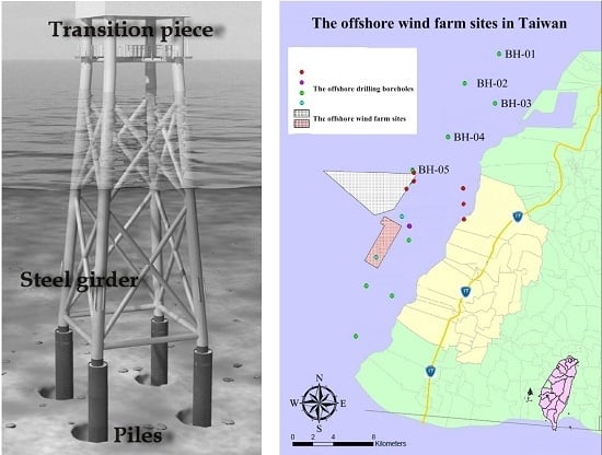
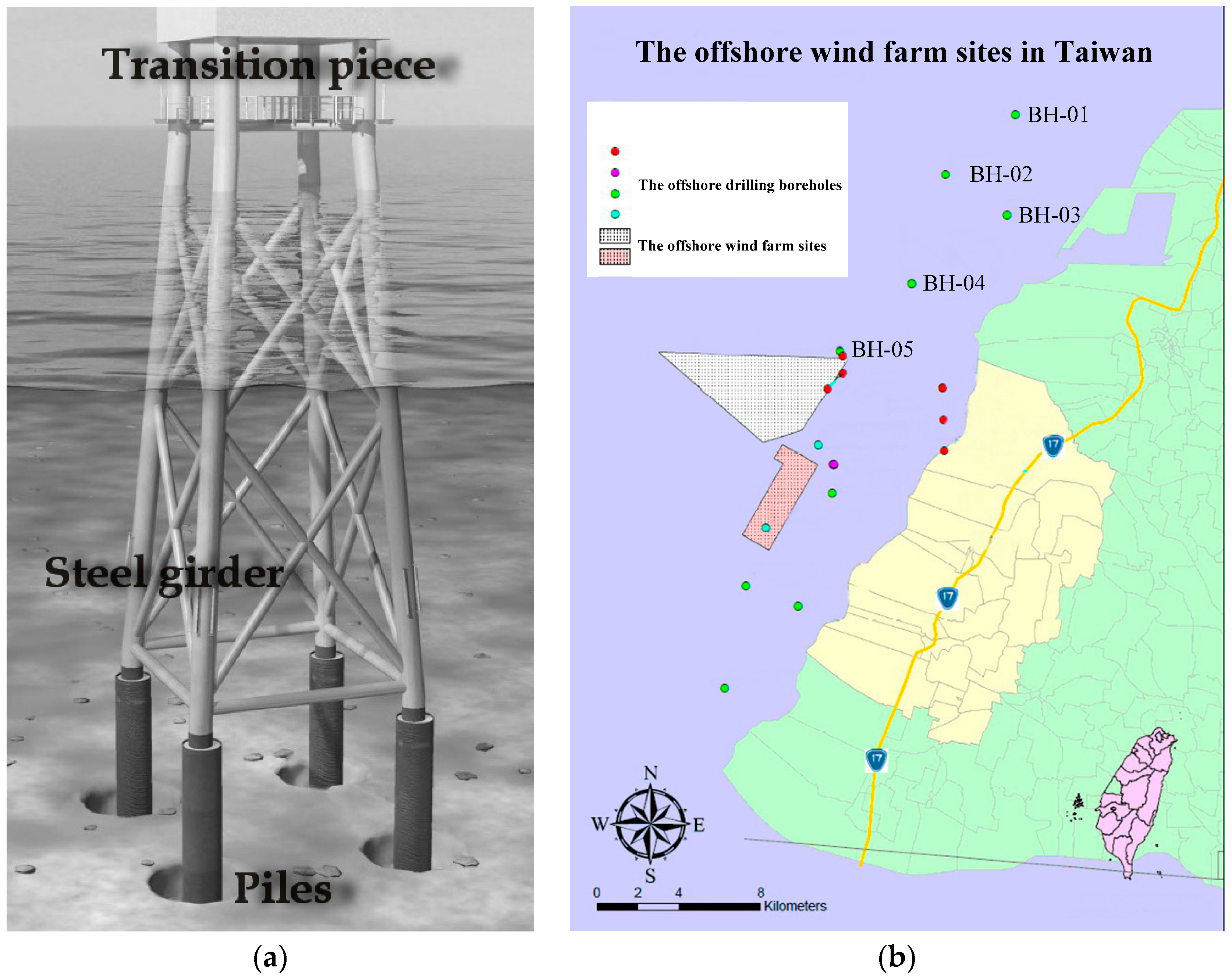
8]. The jacket foundation, as shown in
Figure 1a, is composed of a squared network steel rod design, which is anchored at the bottom using piling activity. The rods of steel in the network are fixed together by welding or by the use of molded sleeves. The attachment of the jacket foundation takes place by piling 3 to 4 anchorage points in the bottom substrate, after which the whole steel construction can be mounted in one piece. A transition piece between the foundation and the tower is placed to help distribute the weight [
9,
10].
Soil-pile-structure interactions during earthquake loading are one of the most important sources of nonlinearity of offshore platforms. The nonlinear Winkler foundation (or dynamic p-y) analysis method for analyzing seismic soil-pile-structure interactions was evaluated against the results of a series of dynamic centrifuge mode tests [
11]. The accuracy of an advanced beam model for the soil-pile-structure kinematic and inertial interactions was also studied [
12]. The dynamic p-y method and the advanced beam model are considerably less complex than the finite difference modeling of the pile and soil continuum. The soil nonlinearity is taken into consideration by means of a hybrid spring configuration consisting of a nonlinear (p-y) spring connected in series to an elastic spring-damper model. However, the nonlinear behavior of the geomaterials, the dynamic pore pressure, and the liquefaction of soil during earthquake loading cannot be considered in the
p-
y method. No consensus exists in the industry, and there is significant interest in improving prediction of the behavior of wind turbine jacket foundations subjected to seismic loading [
13,
14,
15]. Since the analysis of the wind turbine foundation using the effective stress method with the consideration of earthquakes is still not currently popular, we conducted our investigation of the bearing capacity of the jacket foundation pile for an offshore wind farm using effective stress analysis with the consideration of the pore pressure generation and soil/liquid coupled analysis. A new procedure to evaluate the design of the offshore wind turbine foundation pile in the sand and clay inter-layered soil was also proposed.
2. The Offshore Wind Farm Site in Taiwan
According to the preliminary studies on offshore wind farm site selection off the west coast of Taiwan [
16], the wind resources in the Changhua County offshore area are abundant and ideal for offshore wind farm development. Hence, the offshore area of Changhua County, as shown in
Figure 1b, was chosen to be one of the offshore wind farm sites in Taiwan. The wind farm site is located about 8 to 15 km from shore, at an approximate water depth of 20 to 45 m, which corresponds with the average water depth of 22.4 m and the average distance of 32.9 km to shore of European offshore wind farms in 2014, according to statistics by the European Wind Energy Association [
17].
Site-specific soil investigations were carried out for the wind farm site. All geotechnical designs must be based on a sufficient number of borings, geophysical, and geotechnical tests [
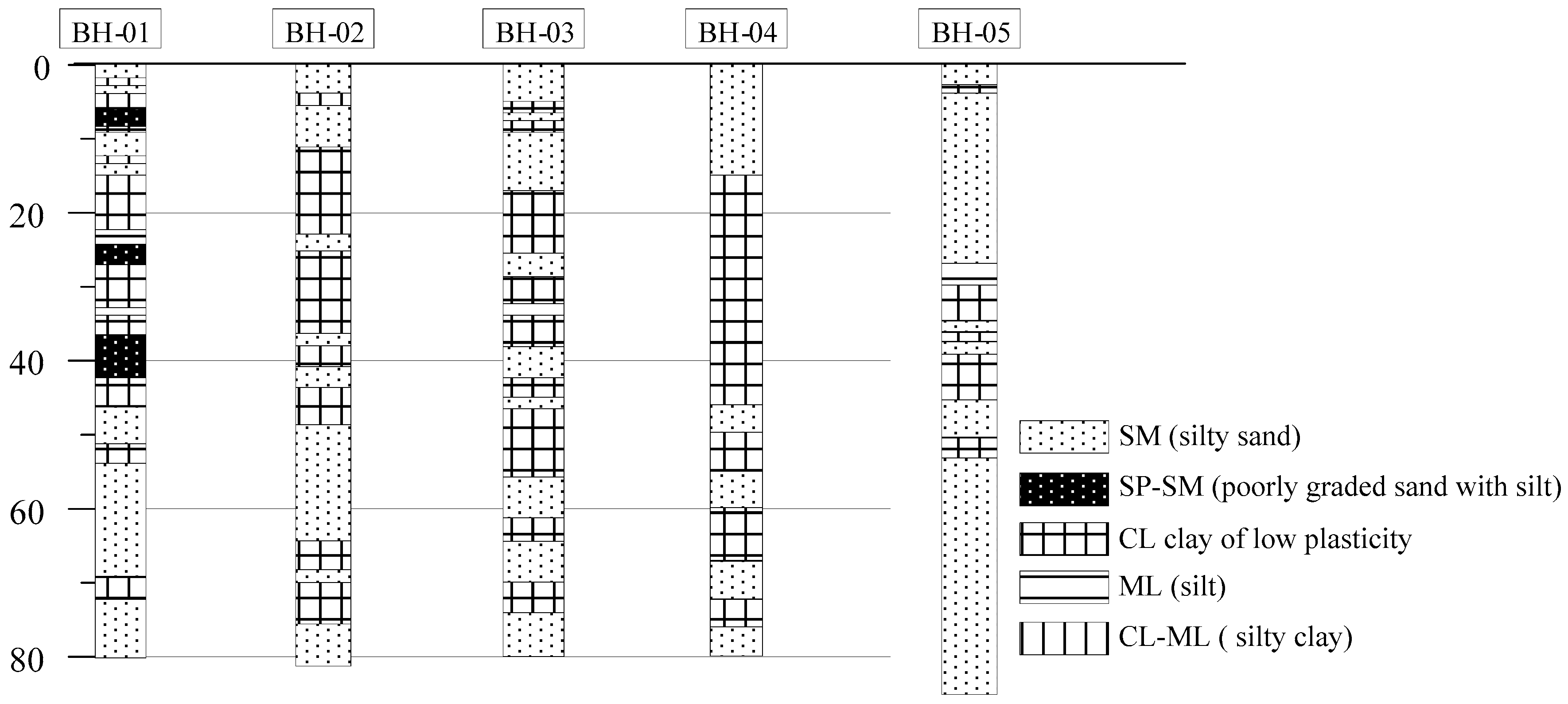
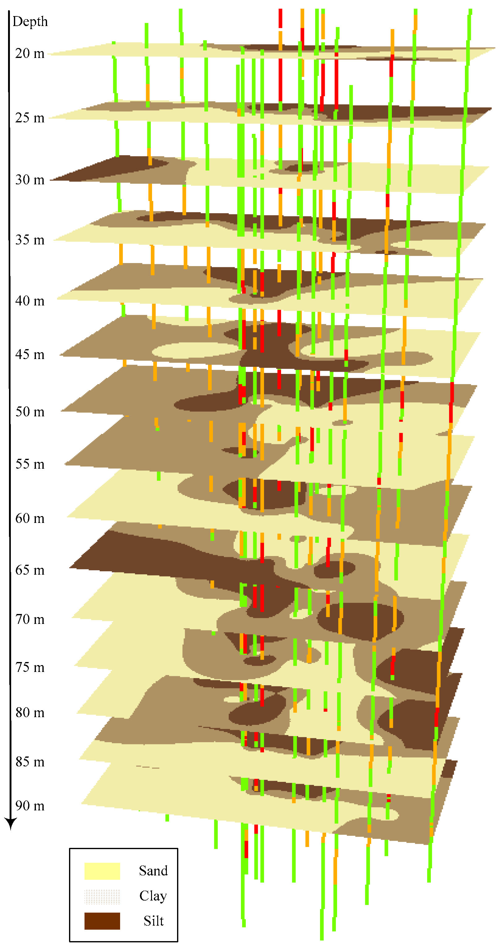
18]. At each foundation of the wind turbine with the integrated use of one borehole, geophysical and geotechnical tests are strongly recommended. If the sites vary in soil features, a different number of suitable boreholes may be made according to the local soil characteristics. From borehole drilling data, we obtained the soil profile as demonstrated in
Figure 2. The soil profile is mainly made up of distinct horizontal layers including silty sand (SP), silt (ML), CL (clay of low plasticity), and inter-layered clay. To clarify the soil characteristics, a three-dimensional soil profile using a geographic information system [
19] was established from the borehole loggings for the offshore wind farm site. From
Figure 3, it was found that the soil in the range of 20 to 35 m under the sea level is sand. The clay and silt inter-layered soil was found in the range of 40 to 80 m under sea level. After 80 m, the soil is mostly a sand layer.
3. Research Methods
The seismic response of the soil-pile-structure interaction during earthquake loading is of importance because the pile foundation is widely used to support superstructures such as wind turbines and offshore platforms. The interaction develops in the absence of a superstructure, which is known as the kinematic interaction. On the other hand, the dynamic response of the superstructure itself to the pile and the nearby soil is referred to as the inertial interaction. Methods such as the dynamic beam on a nonlinear Winkler foundation method and the simplified two-step method are commonly adopted to analyze the seismic soil-pile-structure interaction [
20]. These methods usually uncouple the superstructure and foundation portions in the analysis. Modern seismic codes, for example Eurocode 8 [
21], requires the evaluation of the bending moments developed due to kinematic interaction under the extreme combination of ground profile involving layered soil and moderate or high seismicity zone conditions. Accordingly, the development of a numerical modeling approach for load bearing characteristics including the bending moments developed due to the kinematic interaction of the jacket foundation pile for offshore wind turbines on the west coast of Taiwan was proposed in this study.
The commercial software, Fast Lagrangian Analysis of Continua (FLAC) [
22], was used for the numerical analyses. Although analyses with the consideration of dynamic pore pressure and the liquefaction model have been made in the past, the study on the prediction of the soil-structure interaction behavior of wind turbine jacket foundation piles subjected to seismic loading, especially in earthquake prone area, is hardly found. The purpose of the numerical modeling in this study does not intend to develop numerical codes, but to conceptualize the problem, such as the procedure to evaluate the design of offshore wind turbine foundation piles in the sand and clay inter-layered soil, which was emphasized.
Seismic concerns with regards to the numerical modeling focus on the development of large displacements that could endanger the safety and serviceability of the jacket foundation pile. Such movements depend on the earthquake loading, the design length of the pile, and the strength properties of the soil materials. For the prediction of the soil-structure interaction behavior of wind turbine jacket foundation piles, the finite difference code, FLAC, is used for the static and dynamic analyses. The behaviors of the geomaterials are described by an elasto-plastic Mohr-Coulomb constitutive model. The assumption of the Mohr-Coulomb model constitutes an efficient tool for the investigation of the displacements under seismic loading. Coupled dynamic-groundwater flow calculations were also considered in the analysis. The assumption of an empirical equation proposed by Martin et al. [
23], is adopted in the study. The details of the numerical modeling are given below.
3.1. The Dynamic Pore Pressure Generation Model
To examine the influence of earthquake acceleration, numerical analysis was adopted to simulate the nonlinear dynamic behavior of soil-sheet pile structural interactions. Numerical simulations of the mechanical behaviors of soil materials were divided into two types. The first is the total stress analysis. The total stress analysis assumes that the constitutive laws for soil materials are based on the relationship between the total stress and strain. Therefore, if strain variation occurs in the soil, only the total stress is altered. The fluctuations of the effective stress in the soil cannot be described. Fluctuations in pore water pressure cannot be calculated if the changes in effective stresses in the soil during an earthquake cannot be described. The second type of numerical simulation is the effective stress analysis. The effective stress analysis indicates that under the effect of dynamic shear stress, the pore water pressure of soil increases with the dynamic shear stress of earthquakes. Thus, if a constitutive law based on effective stress is included in the numerical stress analysis, the distributions of pore water pressure, effective stress, and deformation in soil can be determined by conducting a dynamic effective stress analysis.
The effective stress analysis considers the pore water pressure excitation mode. This study employed the FLAC program embedded with the Finn [
24] model for effective stress analysis. The calculation is based on the explicit finite difference scheme to solve the full equations of motion, using lumped masses derived from the real density of surrounding zones. This formulation can be coupled to the structural element model, thus permitting analysis of soil-structure interaction brought about by ground shaking.
Coupled dynamic-groundwater flow calculations can be performed in the analysis. This mechanism is well-described by Martin et al. [
23], who also noted that the relation between irrecoverable volume-strain and cyclic shear-strain amplitude is independent of confining stress. They supply the following empirical equation, as shown in Equation (1), that relates the increment of volume decrease to the cyclic shear-strain amplitude (γ) where γ is presumed to be the engineering shear stain.
where
,
,
, and
are constants.
is the increment of volume strain and
is the accumulated irrecoverable volume strain. An alternative, and simpler, formula is proposed by Byrne [
25] as shown in Equation (2). For the Byrne model,
and
. This study adopted the Finn and Byrne model [
25] which was revised from the model proposed by Martin et al. [
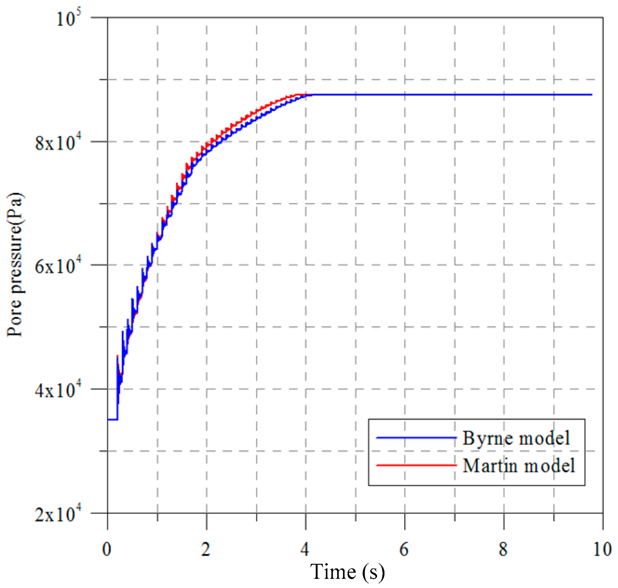
23]. The Finn and Byrne model was selected because only two parameters are needed for the analysis. Due to the difficulties and limitations for conducting geotechnical investigations in deep water, a two-parameter model such as the Finn and Byrne model is preferred in the planning stage. In addition, it is of importance that the two parameters of the model can be directly obtained from the standard penetration tests. To clarify the difference of the Martin model and the Finn and Byrne model, we first conducted a numerical experiment. The parameters for this test are listed in
Table 1. The width and the depth used in the experiment are 50 m and 5 m, respectively. A sine wave with a maximum amplitude of 0.005 m and a frequency of 5 Hz was used for the input of the cyclic loading. The total computing time is 10 s. The computed pore water pressures at three observed points at different depths were recorded during the computation. As one can see the results obtained from the Martin model and the Finn and Byrne model are almost consistent with each other as shown in
Figure 4.
3.2. Numerical Modeling of Earthquake-Induced Liquefaction
It is well known that earthquakes may cause the liquefaction of the seabed [
26]. Earthquake-induced liquefaction is the first key issue to evaluate at a potential wind farm site. Numerical modeling of liquefaction effects is performed in practice and research using a wide range of constitutive models and numerical procedures. The constitutive models vary in complexity, depending on which aspects and details of liquefaction behavior they are intended to approximate. In this study, the numerical modeling of liquefaction effects is performed using the Finn and Byrne model with the consideration of coupled dynamic-groundwater flow calculations.
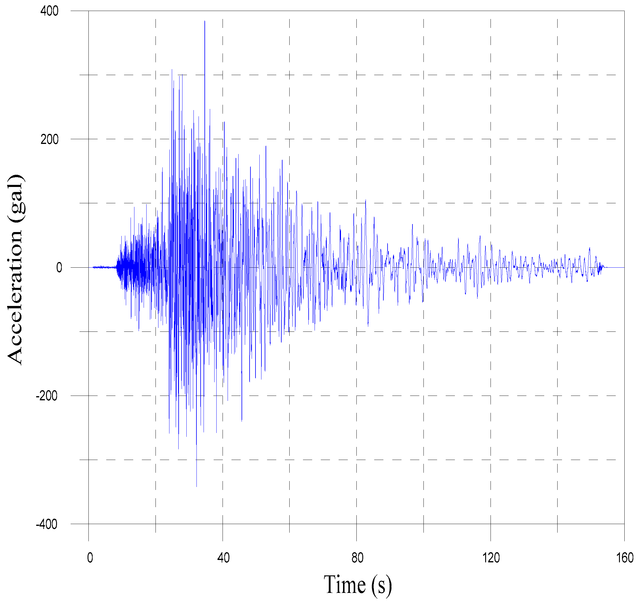
Figure 5 depicts the accelerations of design earthquake motions for a 475-year return period for the analysis [
27].
Because of the possibility of encountering stratum laminations in practice, this study adopted actual drilling data for stratum lamination. Therefore, multi-layered strata existed in this case. The width and the depth used in the numerical modeling are 160 m and 80 m, respectively. In total 1200 zones were used in the analysis. The soil parameters are listed in
Table 2 according to the actual drilling data. In the analysis, mechanical damping must be provided to consider energy losses during dynamic analysis. Rayleigh damping, which involves mass and stiffness dampers, was adopted for this case analysis. Critical damping ratios, generally 2% to 5%, have been suggested for geotechnical engineering materials [
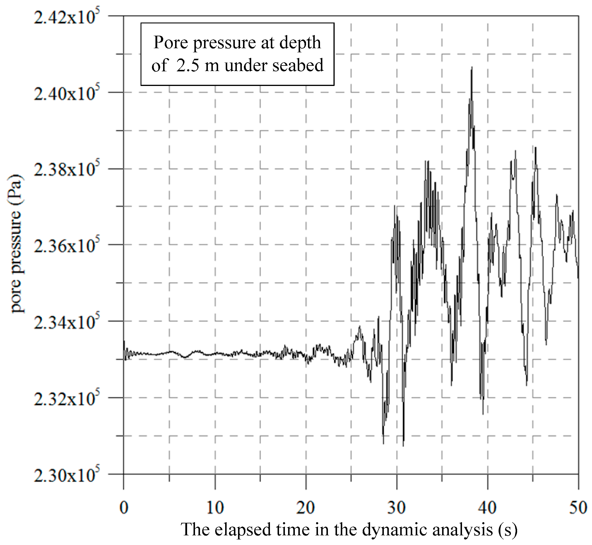
22]. However, regarding the input parameters of resonance frequency, practical determination of the resonance frequency of complex strata still remains difficult. In this study, we adopted the critical damping ratio and the resonance frequency of 5% and 6 Hz, respectively.
Results obtained demonstrate that the liquefaction of the seabed may occur at the depth of 2.5 m. In addition, the excitation of the pore pressure of the seabed has also been observed as shown in
Figure 6.
3.3. Analysis of Bearing Capacity of the Jacket Foundation Pile
3.3.1. Validity of the Analysis of Bearing Capacity
In order to investigate the pile bearing capacity of the jacket foundation in a typical soil profile, we first conducted a simplified analysis based on the building code of the ministry of the interior, the Republic of China. The evaluation of the pile bearing capacity from the building code is basically similar to the traditional analytical method which can be found from the textbook [
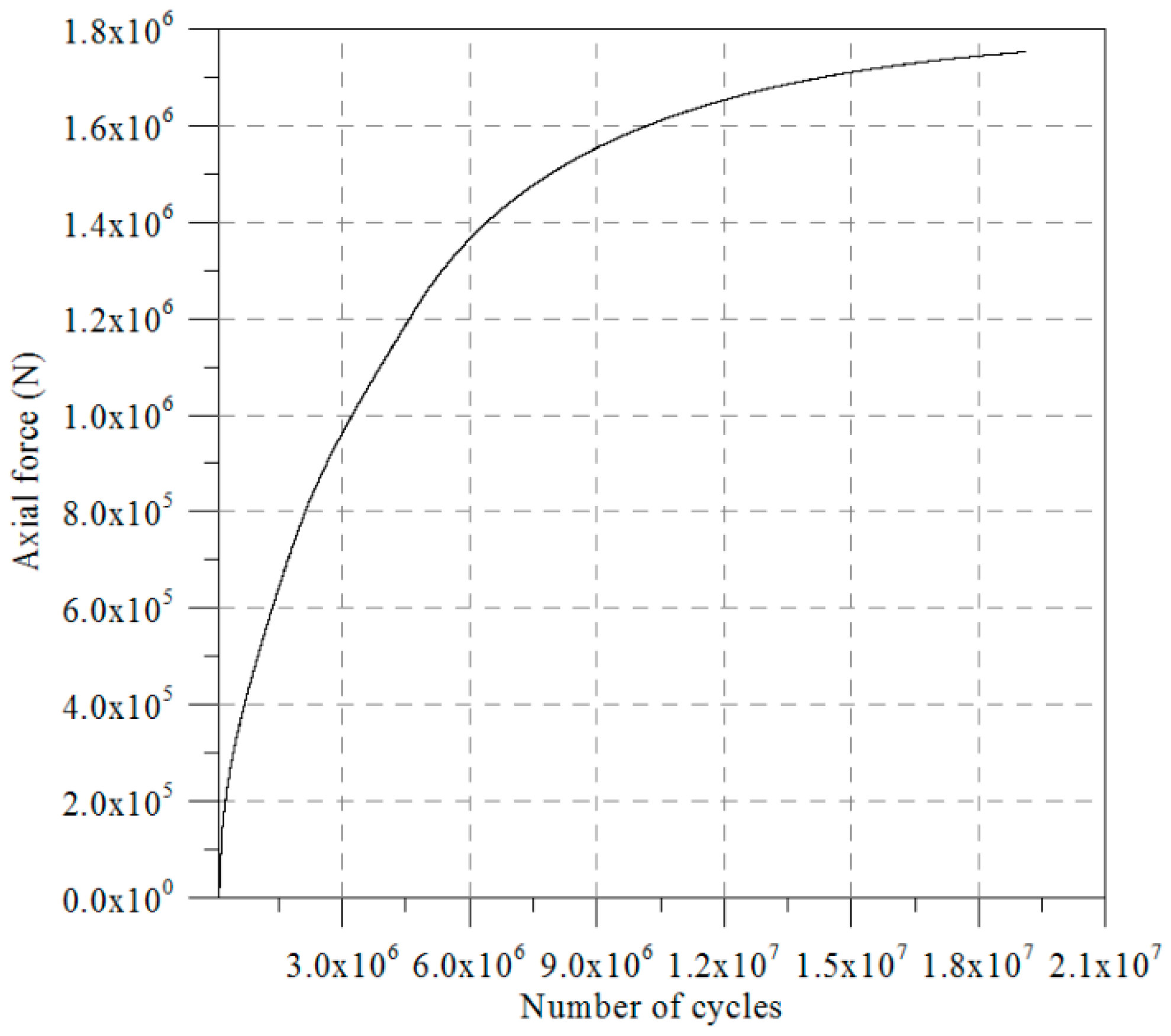
28]. Then, the pile bearing capacity of the jacket foundation was evaluated again using the numerical analysis by FLAC with the same configurations as those in the simplified analysis based on the building code. In the numerical analysis, the width and the depth of the domain are both 20 m. In total, 100 zones were used in the analysis.
Table 3 shows the parameters used in both the simplified analysis based on the building code and the numerical analysis. Results obtained from the numerical analysis are depicted in
Figure 7. It was found that the values of the pile ultimate bearing capacity of a monopile computed from the simplified analysis based on the building code and the numerical analysis were 2.08 × 10
6 N and 3.5 × 10
6 (1.75 × 10
6 × 2) N, respectively. For the numerical analysis, the bearing capacity is twice the calculated value because the analysis domain of the pile is symmetrical and only half of the pile is analyzed. It is interesting to note that the pile ultimate bearing capacity from the simplified analysis is smaller than that computed from the numerical analysis, which means that the results from the simplified analysis may be more conservative than those from the numerical analysis.
3.3.2. Static Analysis of Bearing Capacity of the Jacket Foundation Pile
According to the results from the geotechnical investigations, the soil model with the foundation for the numerical analysis can be built as shown in
Figure 8a. Based on the soil parameters listed in
Table 4, the seabed soil was modeled as an elastic-plastic model based on the Mohr-Coulomb failure criterion. A pile with a depth of 60 m and a diameter of 2 m was considered. In the numerical model, the width and the depth of the domain are both 80 m. In total, 2000 zones were used in the analysis. The vertical loading was continually applied to the top of the pile. The pile is represented by beam elements located along the pile periphery and connected to the soil via the interface elements. In this way, the pile/soil interaction can be included in the analysis. The parameters adopted for the pile and the interface elements are listed in
Table 5.
Results obtained from the numerical analysis are depicted in
Figure 8b. The values of the pile ultimate bearing capacity computed from the numerical analysis was 16,000 × 2 = 32,000 kN, in which the result is twice the computed value because only half of the pile was analyzed. Since there are four piles connecting the jacket substructure to the seabed, the total bearing capacity of the jacket foundation is 128,000 kN. The total bearing capacity of the jacket foundation obtained shows that the jacket foundation is relatively safe under the design load.
3.3.3. Dynamic Analysis of Bearing Capacity of the Jacket Foundation Pile
Based on the numerical model established in the previous section, the dynamic analysis was performed using FLAC. The accelerations of the design earthquake motions for a 475-year return period, as depicted in
Figure 5, were applied directly to the model. Based on the standard penetration test data from the site investigation, the two parameters of the Finn and Byrne model used for the analysis are listed in
Table 6. Dynamic free-field boundary conditions that simulate the effect of an infinite elastic medium surrounding were adopted. The sea level is 10 m above the seabed. The analysis of soil-structure interaction coupled with the pile foundation was modeled with the consideration of the ground shaking. The dynamic analysis was also coupled to the Finn-Byrne model where time-dependent pore pressure change associated with liquefaction can be considered.
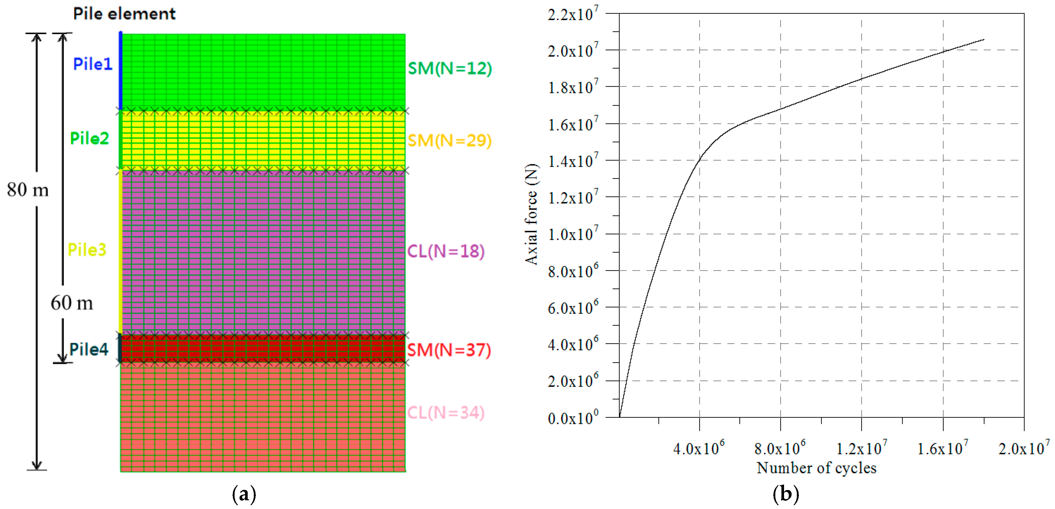
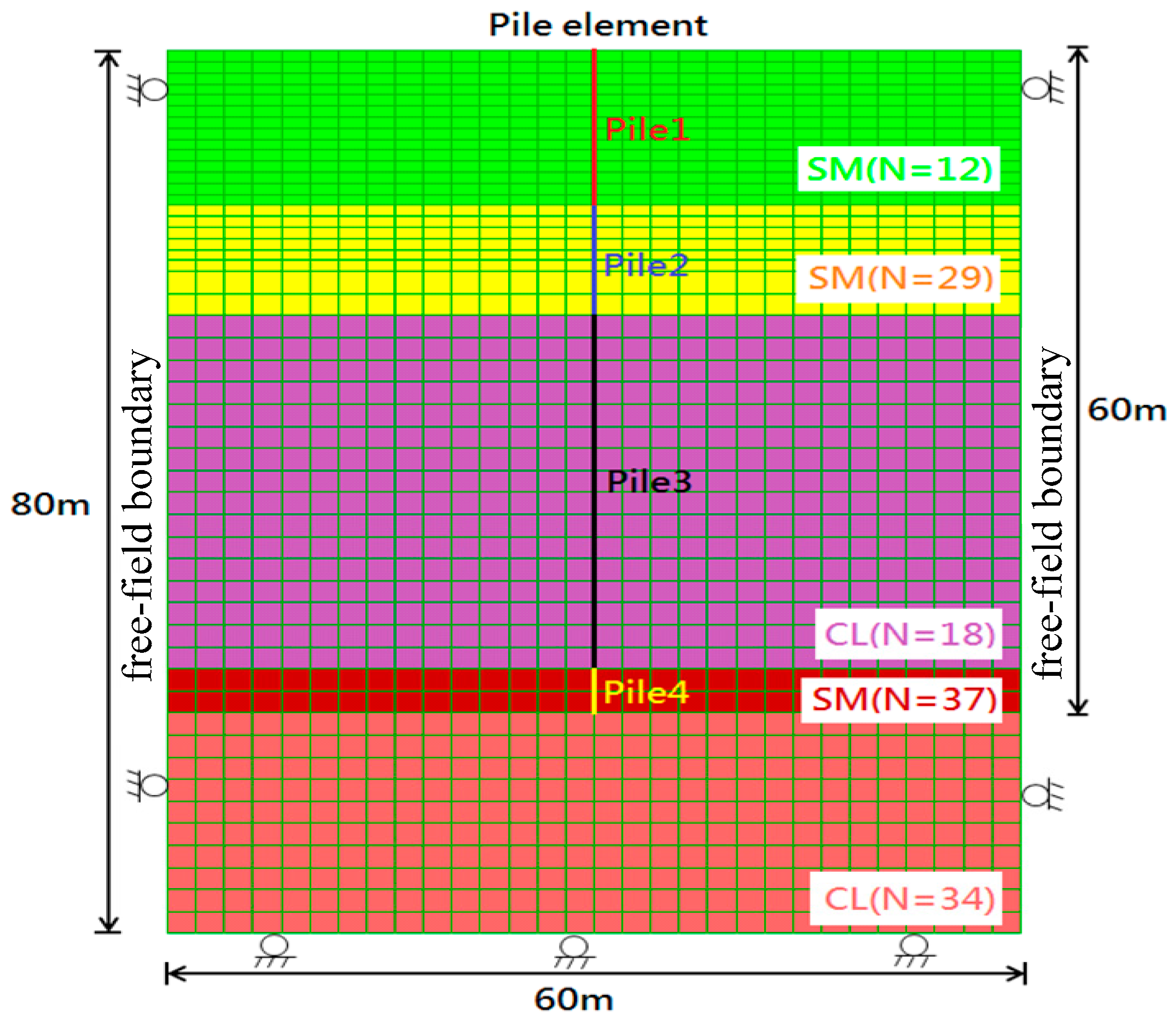
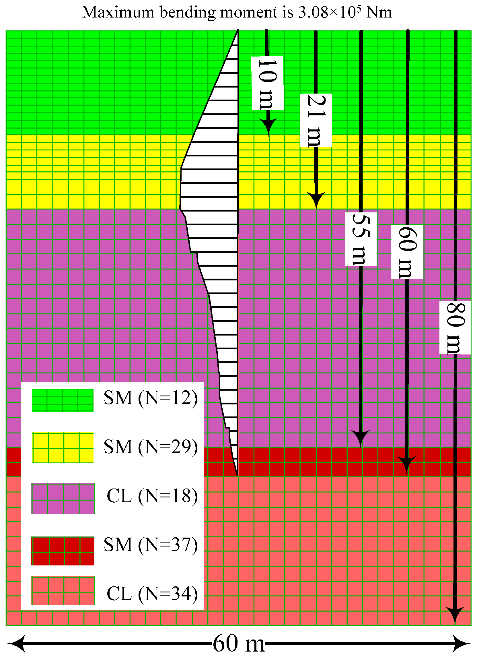
A pile with a depth of 60 m and a diameter of 2 m was considered. In the numerical model as shown in
Figure 9, the width and the depth of the domain were 60 m and 80 m, respectively. In total, 1500 zones were used in the analysis. The designed vertical loading was applied to the top of the pile. The parameters adopted for the pile and the interface elements were the same as the static analysis and are listed in
Table 4 and
Table 5.
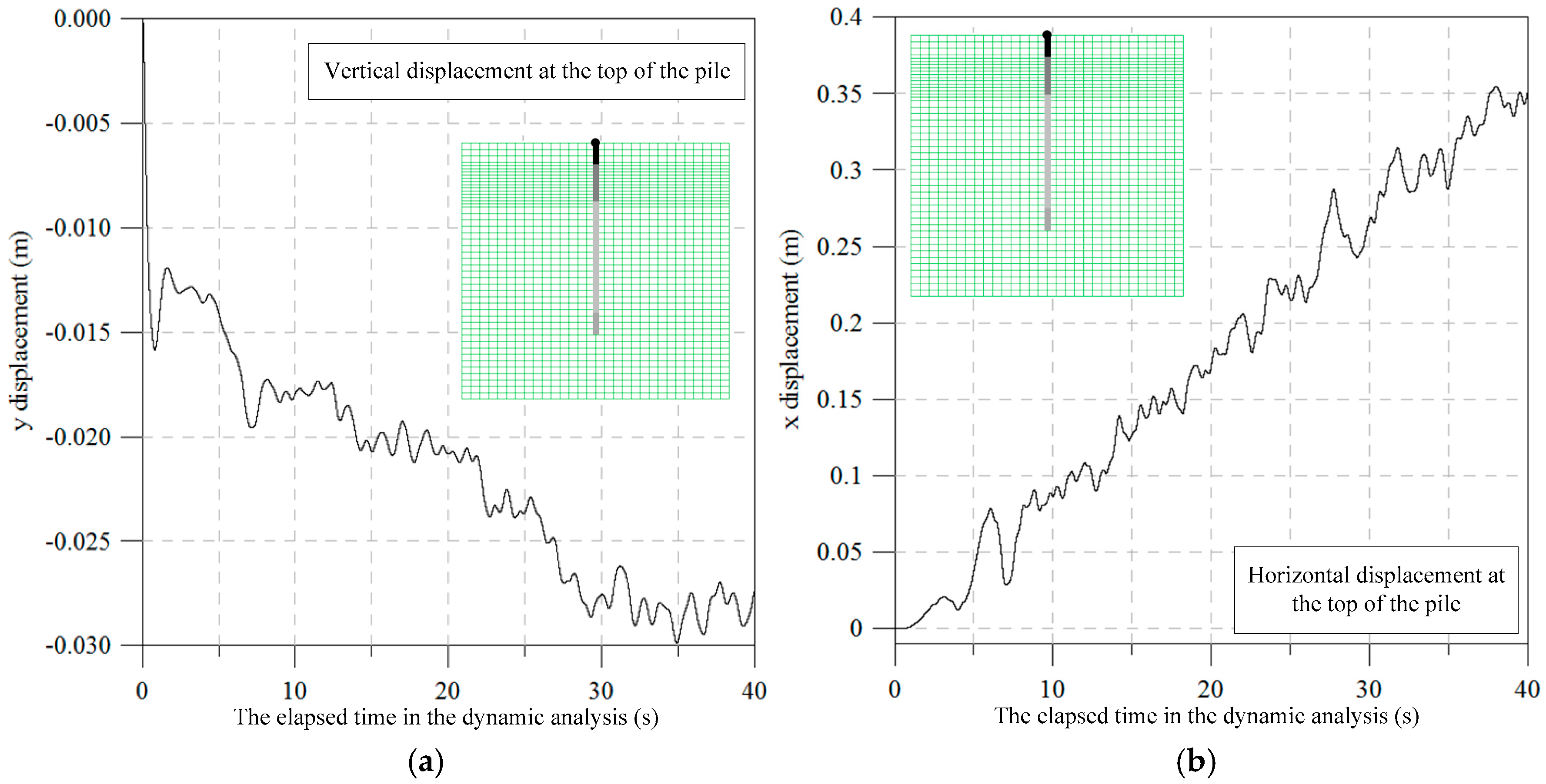
Results obtained from the numerical analysis are depicted in
Figure 10a,b. It was found that the maximum vertical displacement of the top of the pile was 0.35 m and the maximum horizontal displacement of the top of the pile was 0.03 m. The historical data of the vertical and horizontal displacement of the top of the pile are also depicted in
Figure 10a,b, respectively.
Figure 11 shows the computed bending moment of the pile. It was found that the maximum bending moment is 3.08 × 10
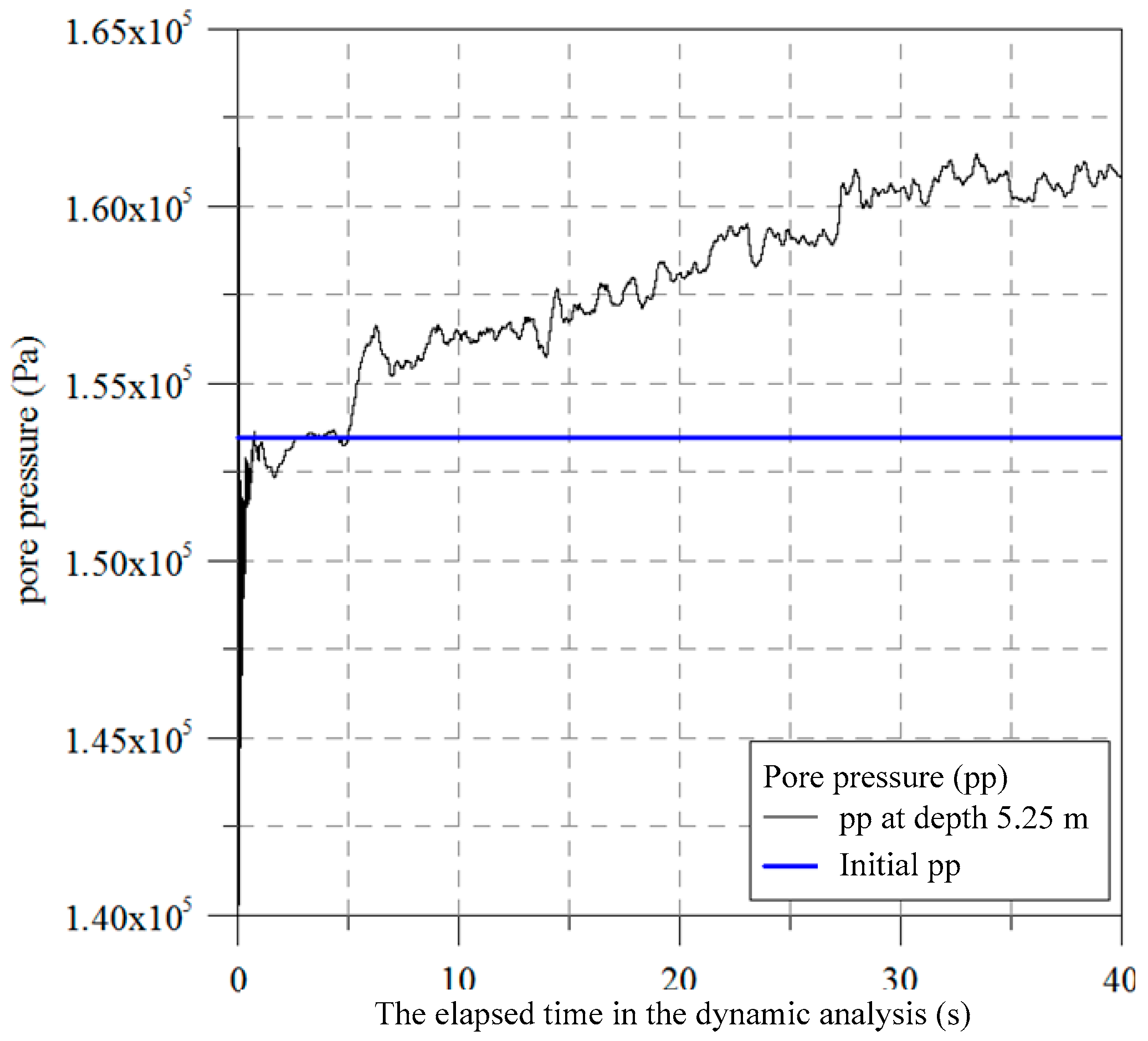
5 Nm and is still in the range of the elastic deformation. However, the ground foundation deformation computed from the ultimate loads of the 475-year return period may exceed the allowable ground foundation deformation, which indicates that the jacket foundation may fail or need to be repaired. An observation point was placed at a depth of 5.25 m to measure the pore water generation. The excitation of the pore pressure for the seabed was found and is depicted in
Figure 12. The value of the initial pore water pressure was also plotted in
Figure 12. The results indicate that the pore pressure at a depth of 5.25 m was excited during the dynamic analysis. An excess pore water pressure of 7 kPa was developed. The results demonstrate that the seabed soil at a shallow depth may have a greater potential to be liquefied.
4. Conclusions
A pioneering study on numerical modeling of dynamic behavior for the jacket foundation pile of offshore wind turbines on the west coast of Taiwan is presented. Because no consensus exists in the industry, there is significant interest in improving prediction of the behavior of wind turbine jacket foundations subjected to seismic loading. Effective stress analysis, with consideration of the Finn-Byrne pore pressure generation model, was conducted. In addition, the analysis of soil-structure interaction coupled with the pile foundation was modeled, with consideration of the ground shaking. A new procedure to evaluate the design of offshore wind turbine foundation piles in the sand and clay inter-layered soil was also proposed.
Static analysis of the bearing capacity of the jacket foundation pile was also conducted. It was found that the total bearing capacity of the jacket foundation pile was relatively safe under the design load. However, results obtained from the dynamic analysis of the bearing capacity of the jacket foundation showed that the ground foundation deformation computed from the ultimate loads of a 475-year return period may exceed the allowable ground foundation deformation, which indicates that the jacket foundation may fail or need to be repaired. In addition, the excitation of the pore pressure for the seabed was also found which indicated that the seabed soil at a shallow depth may have great potential to be liquefied. Nevertheless, the results show that the design process for the jacket foundation pile proposed in this study can properly reflect the interaction behavior of the foundation and the soil. In addition, the pore pressure generation model can be used to simulate the soil liquefaction. The proposed method can also be very useful to evaluate the design capability for the offshore wind turbine jacket foundation.


