1. Introduction
With the raising awareness of environmental problems and increasing demands for power supply reliability and quality, microgrids are becoming a promising solution to integrate renewable energy resources and to modernize the current electrical system at thee distribution level. A microgrid can be described as a cluster of loads, distributed generation (DG) units and energy storage system (ESS) operated in a coordinated way to provide power supply to customers with higher reliability, and interacting with the utility grid at the point of common coupling (PCC) to import/export power and provide ancillary services [
1,
2,
3]. To fully take advantage of microgrids’ potential, numerous research works are dedicated to testing new microgrid control strategies [
1,
2,
3,
4,
5,
6,
7,
8,
9,
10,
11,
12,
13,
14,
15,
16,
17,
18,
19,
20,
21,
22,
23,
24,
25,
26,
27].
In order to control and manage effectively a microgrid, hierarchical control is proposed to coordinate the resources according to different time scales [
3]. In the lower level which is also named primary control and has the highest control bandwidth, a droop controller is often adopted to share the load demand among DGs. In the higher lever, with relatively lower control bandwidth, advanced control purposes, such as frequency and voltage recovery, reactive power compensation, economic dispatch, unbalance and harmonics compensation, are identified for the energy management of microgrids.
Previously, the major concern for the control of microgrids was focused on sharing the active/ reactive power among the DGs based on their respective kVA ratings, through a virtual impedance loop [
4,
5,
6,
7], adaptive tuning [
8], and so on. With the increasing concern about the efficiency and cost of systems, higher level controllers for energy management are attracting more and more interest. Among the different tasks for the aforementioned energy management, the economic dispatch problem (EDP) is vital for the improvement of system efficiency while facilitating the commercialization of the microgrid. This is especially needed when there are various types of DGs coexisting in a microgrid.
The higher level control can be classified into two types according to how they realize the economic dispatch. One is based on centralized control [
9,
10,
11,
12,
13], while the other is based on distributed control [
14,
15,
16,
17,
18,
19,
20,
21,
22,
23,
24,
25,
26,
27]. In order to dispatch the power optimally, in [
9,
10,
11,
12], the authors use a centralized controller to make the decisions for generating the optimal power generation commands based on the generation cost. In [
13], the regulation of the power generation is realized by directly changing the droop coefficients according to the stability constrained optimization. Although centralized control enjoys the merits of accurate control and easy implementation, it encounters the following challenges: First, it requires heavy communication overheads due to the bidirectional communication links between every single unit in the system and the centralized controller. Second, due to the existence of a single centralized controller, which is needed to tackle the large amount of data from the sub-units and to make the decisions for the whole system, it places high demands on the computational capability of this unit, and renders the system susceptible to a single point of failure if this centralized controller fails. Moreover, as customers are becoming more aware of the cases where private information might be revealed in the patterns of how they consume the electricity, more customers (e.g., the owners of the resources in the microgrid) might not be willing to pass the consumption data on to the centralized controller.
In light of these concerns, decentralized control strategies are proposed as an alternative to overcome these shortcomings. Some of the decentralized methods directly use droop control to dispatch the power economically in a distributed way, due to the fact that it is simple to implement, requires no communication, and relies only on the local information. In [
14], the operation cost information is incorporated in a weighted droop expression through calibrating the minimum and maximum operation cost in a linear way with respect to the droop gain. Although it works very well for most cases, it will lose its effectiveness when two DG units have the same maximum and minimum generation costs. Another work improves upon this idea by introducing a weighted droop expression which considers the nonlinear characteristic of the operation cost function [
15]. However, despite the merit that there is no communication overhead, this method lacks adaptability to external changes of the cost without communication, which enables the higher level control to obtain cost information in a timely way.
Another possibility is using a multiagent approach, in which either a sub-function or a unit in the microgrid are taken as agents. Each agent has the properties of autonomy, reactivity, pro-activeness and social ability [
16,
17,
18,
19,
20,
21,
22,
23,
24,
25,
26,
27], and they exchange information with the corresponding agent to make the decisions locally for collaborative purposes. There are mainly two concepts that can be applied to form a multiagent platform. Some multiagent systems in microgrids are based on the market concept to maximize the benefits of generation units by analyzing the effects and evaluation of different auction algorithms [
16,
17,
18,
19]. This is also consistent with the market scenarios in a large power system. However, for a small scale network such as a microgrid, the computation load is too heavy. Moreover, although the auction process is decentralized, a special unit is still needed to collect the power requests from other users.
By combining the advantages of multiagent systems with simplicity, various consensus algorithms are proposed to manage the resources of a microgrid in economic fashion [
24,
25,
26,
27]. In [
24], a consensus-based algorithm is proposed to coordinate the ESS units of a microgrid according to the efficiency. However, one leader agent is needed to broadcast the total active power deviation, thus compromising the decentralization feature. In [
25], although a consensus algorithm is developed to optimize the cost, it is only validated by using numerical simulations. In [
26,
27], an incremental cost consensus is proposed in the smart grid context, nevertheless the details of the power regulation realization are not given.
In this paper, a multiagent-based distributed operation cost minimization method is proposed to dispatch the power economically based on the generation cost of different DGs. Each DG is acting as an agent which regulates the power according to the command obtained through an incremental cost consensus algorithm by using sparse communication among the direct neighbours of each unit. First, the details of the proposed power regulation strategy based on frequency scheduling are introduced. The small signal model of the power regulation strategy by using frequency scheduling is developed, and the sensitivity of the control parameters in the controller is investigated. The proposed control strategy based on multiagent systems is then presented to set the optimal power commands. Experimental case studies of an AC microgrid with three different DG units are carried out to verify the proposed control methodology.
The main contribution of this work lies in two aspects. One is the formulation of the optimization problem for operational cost minimization based on a multiagent system using incremental cost consensus. For the other, this work has proposed a power regulation method based on frequency scheduling to track this optimal command. Overall, this work makes an initial effort to design and implement a distributed approach which combines the local power droop control of all the power electronics units and an incremental consensus algorithm on the optimization layer, and this method has reduced the operation cost of the whole system effectively.
The rest of the paper is organized as follows. In
Section 2, the principle of the proposed frequency scheduling method for power regulation is introduced and analysed through small signal modelling. In
Section 3, the detailed decentralized solution based on a multiagent system for minimizing the operation cost is provided, along with the formulation of the EDP, introduction and analysis of the incremental consensus, and the explanation of the system implementation. In
Section 4, the experimental results are provided for different case studies to validate the proposed control strategy.
Section 5 concludes the paper.
2. Frequency Scheduling for Power Regulation of Droop Controlled AC Microgrid
Droop control is widely used in microgrids to achieve autonomous power sharing without relying on communications. The conventional droop controller in an AC microgrid is expressed as:
where
is the output voltage frequency of the DG unit
i,
is the nominal frequency,
is the frequency droop gain,
is the output active power,
is the output voltage,
is the nominal voltage amplitude,
is the voltage droop parameter and
is the output reactive power. Note that from Equation (1), if
and
are equal for all
i units, the
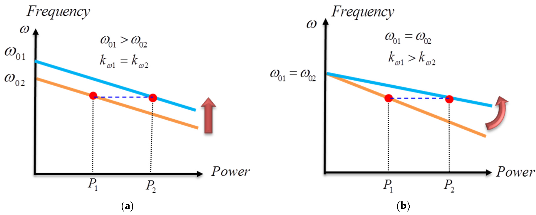
will be equally shared. However, if we want to change the way how real power is shared among different DG units, there are two possibilities to realize it. As can be seen from
Figure 1, either changing the frequency droop gain
or changing the nominal frequency
will result in different power sharing.
In the previous work [
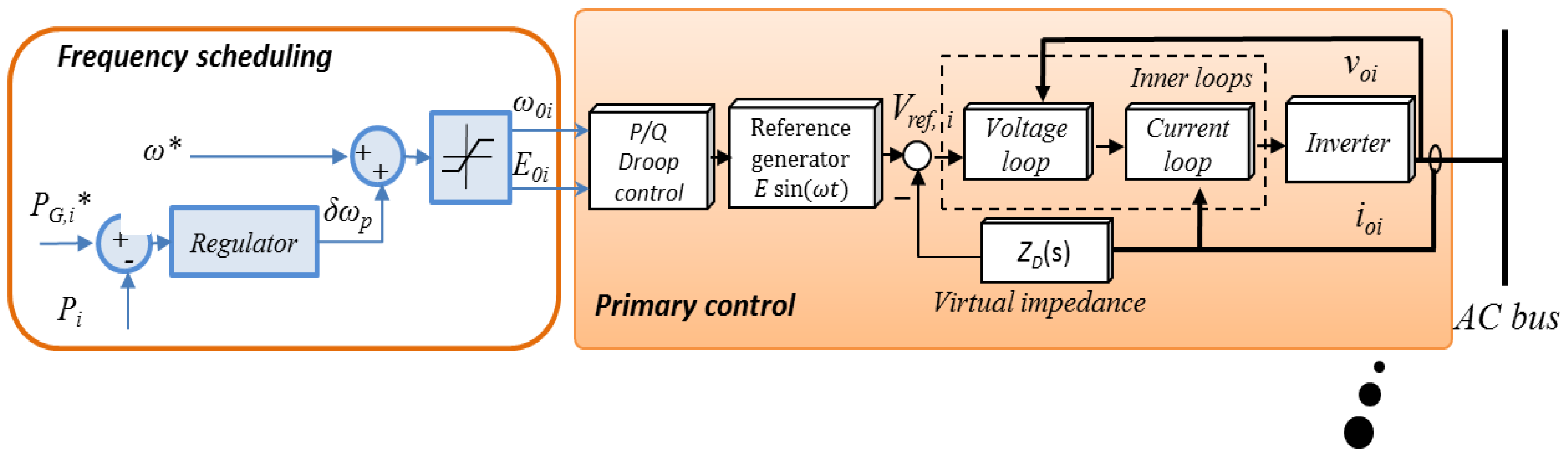
5], adaptive frequency droop gain has been employed to reduce operation cost. Instead of adjusting the droop gain, the possibility of frequency scheduling is investigated in the paper. The control scheme block diagram of each DG is illustrated. As can be seen in
Figure 2, outside the primary control which uses the traditional droop, the nominal frequency is modified according to the command of active power as is shown in the frequency scheduling block. Note here that one of the DGs sets the regulator as a proportional controller while all the others are using a proportional-integral controller in the block of frequency scheduling, since for an islanded microgrid it must have at least one DG unit to balance the supply-demand mismatch.
The frequency scheduling controller can be expressed as:
The generic proportional integrator (PI) controller to regulate active power takes the form:
Thus the frequency droop controller in Equation (1) can be expressed as:
where
,
,
,
and
are the initial nominal frequency, modified term of nominal frequency, the proportional term of the power regulator, integral term of the power regulator and the command of generation power, respectively.
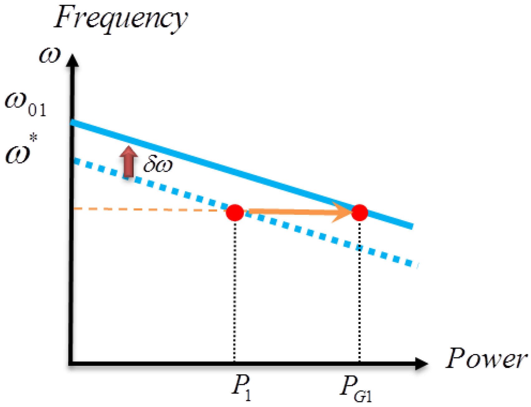
The mechanism of the proposed power regulation based on the frequency scheduling can also be illustrated by frequency droop scheme as in
Figure 3. By adding the modified term to the nominal frequency, the resultant active power generated by unit
i will become exactly the active power command. Note here the modified term can also be negative, and thus some units will reduce the active power generation.
Assuming the output impedances of each converter are mainly inductive which may be enforced by adjusting properly the virtual impedance
ZD(s), active power can be expressed as:
where φ
i,
V,
Ei and
Xi are the power angle, common bus voltage, and the magnitude of the output reactance for DG
i, respectively.
Perturbing Equation (5) at the equilibrium point using Taylor series, the dynamics of power regulation of the system around the operation point in Laplace form can be expressed by the following equations omitting the higher order items [
28]:
Similarly, by perturbing Equation (6) at the equilibrium point and omitting the higher order Taylor series items, the small signal version of this equation can be expressed as:
where
G is written as follows:
where
,
and
are the voltage of inverter
i at the equilibrium point, which can be approximated as
per unit,
per unit,
per unit and
per unit.
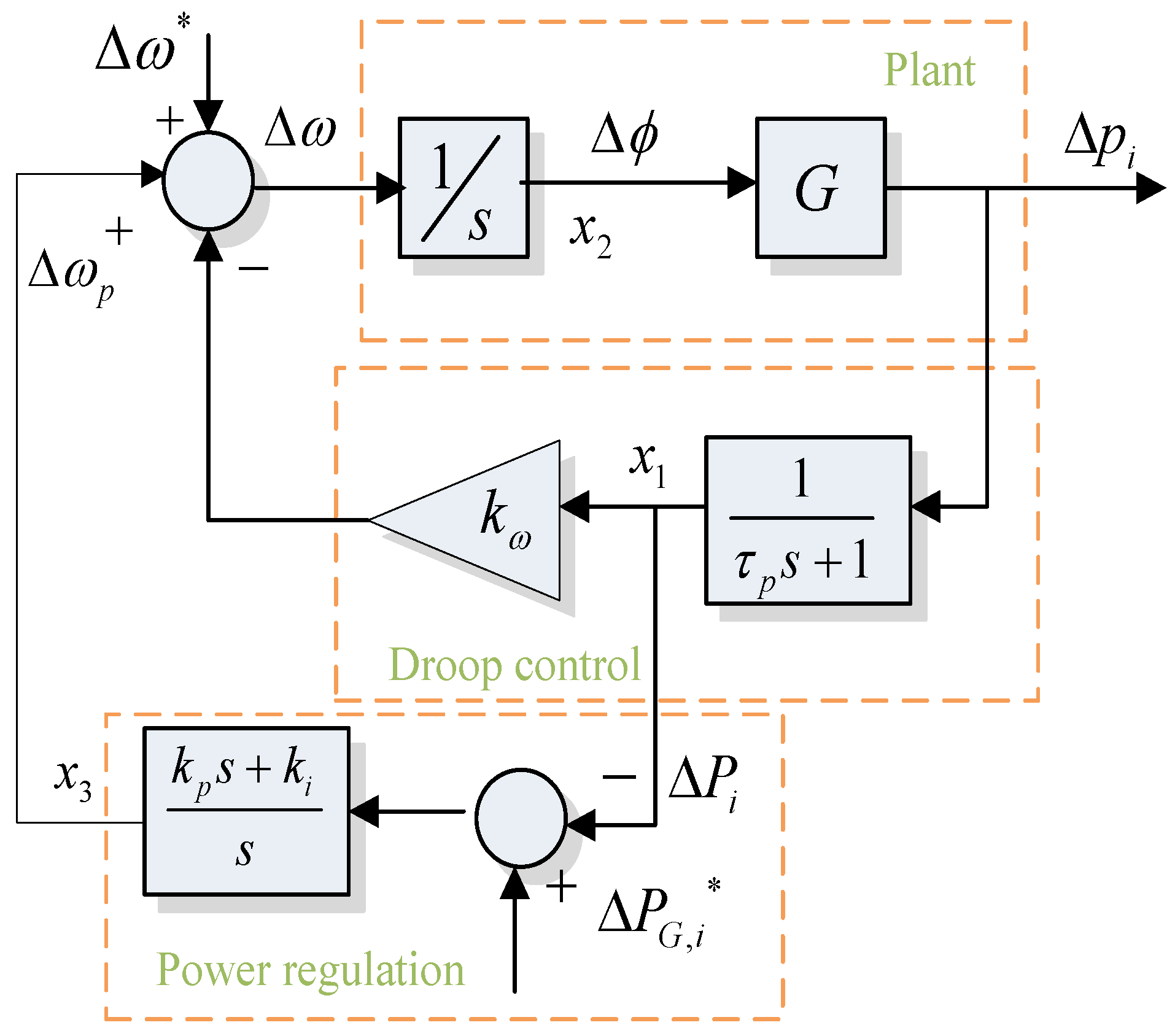
Figure 4 shows the block diagram of the small signal model for power regulation using frequency scheduling. The model includes the droop control model, the plant model, and the power regulation model. The output of the low-pass-filter with the
as the time constants, PI controller for power regulation, and the power angle are chosen as the state variables.
Thus, the small signal model of the power regulation dynamics can be written in state-space form as follows:
where
B is unit vector and state variables
as shown in
Figure 4, input vector
is
and system matrix
A is:
From Equation (12), the eigenvalues of matrix
A are used to analyze the impact of the control parameters over the power control performance on the system stability.
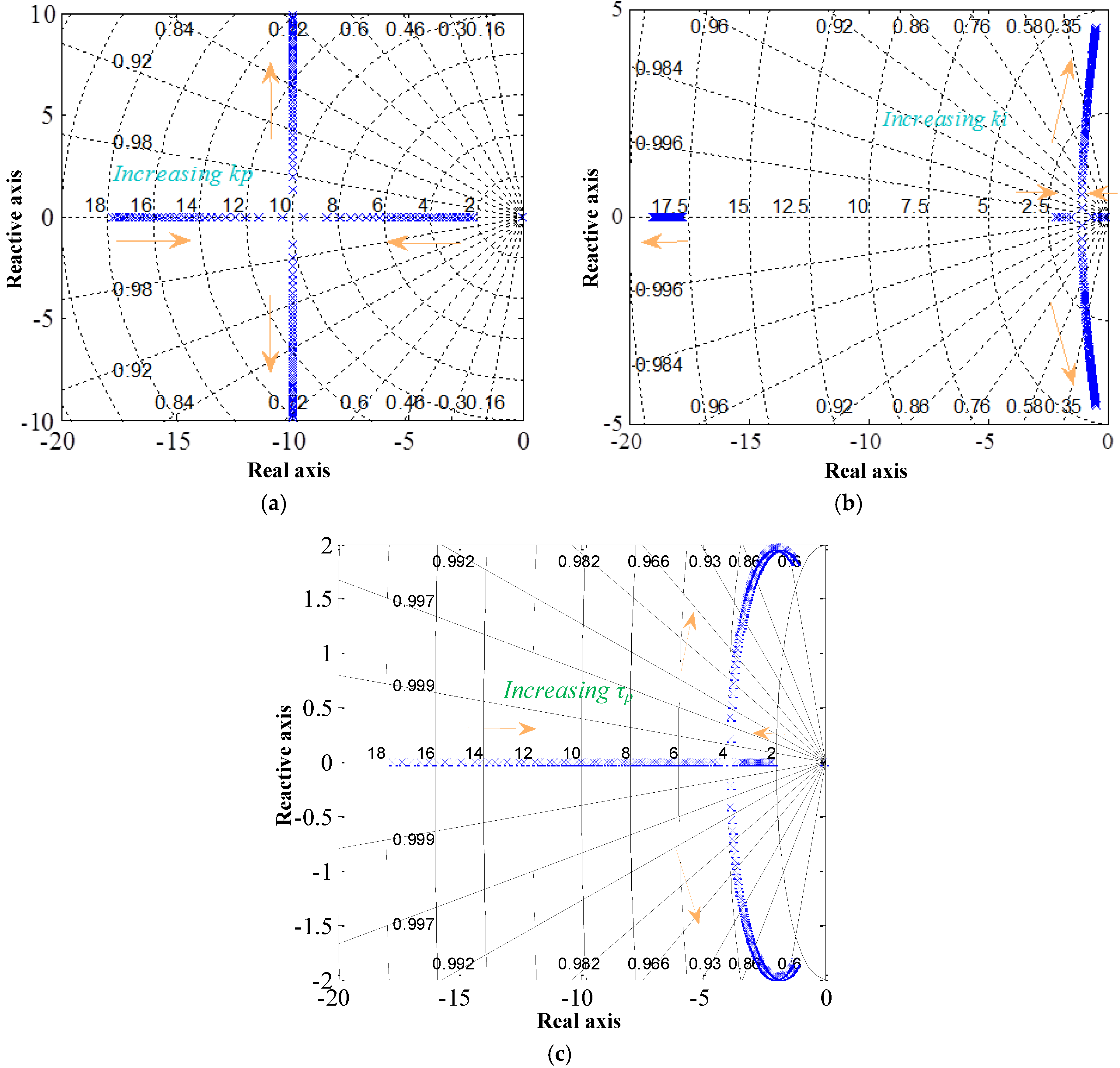
Figure 5a–c shows the trajectory of the modes in function of control parameters.
Figure 5b shows that as the integral term of the PI controller increases, the eigenvalues of the system move toward an unstable region. However, as is shown in
Figure 5a, the proportional term has no significant effect on the stability. As can be seen from
Figure 5c, the time constant of the low-pass filter for power calculation cannot be chosen arbitrarily, the large cut-off frequency will lead the system to instability.
3. Multiagent System for Operation Cost for Operation Cost Minimization Using Incremental Cost Consensus
In this section, the proposed distributed implementation of economic dispatch for operation cost minimization is introduced. Firstly, the problem of operation cost minimization is formulated. Then the proposed incremental cost consensus algorithm is explained, with its convergence analysis and convergence dynamic analysis. Finally, the implementation of the whole multiagent system is given.
3.1. Cost Function of a Distributed Generator Unit
For renewable energy generators (e.g., wind turbines and photovoltaic systems), we can assume the operation cost is zero. Moreover, normally these generators are working under maximum power point tracking (MPPT) mode to maximize the utilization of the renewable energy, hence they cannot be taken as the controllable generation to effectively participate. On the contrary, their variable generation along with unpredictable load requires consistent optimization for EDP. Here in this work, the backup generator, e.g., fuel cell, diesel generator, and batteries are taken as the unit for EDP. Generally, the cost function of the fuel generator can be written as a quadratic cost function [
8,
9,
29]. For the ESS, considering the power loss during charging and discharging operations, the cost function has a similar pattern to those for fuel generators [
24]. The detailed derivation of the cost function can be found in [
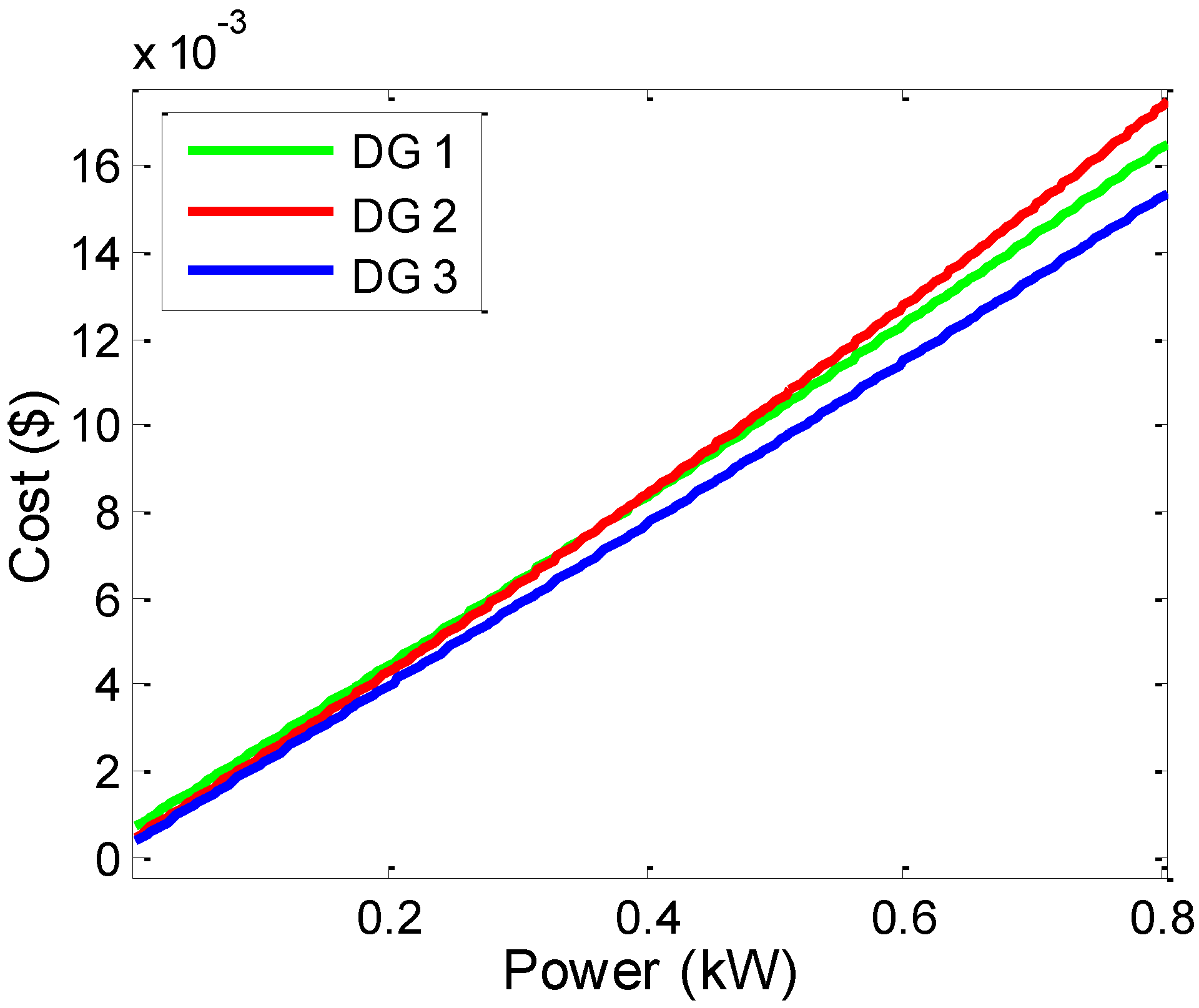
30]. In general, the cost function of the generator dispatched in EDP can be written as:
where α
i, β
i and γ
i are the coefficients related to the cost function for generation
i.
Figure 6 illustrates the operation cost function for three different units (DG1, DG2, and DG3). The coefficients data can be found in
Table 1.
3.2. Problem Statement
The purpose of the EDP is to minimize the operation cost of all the dispatchable generators. Thus the total cost of operation of a microgrid with
n dispatchable generators is the summary of the cost of all of them, which can be expressed as:
where C
total is the total cost of the whole system.
Considering the constraints of power balance and power generation limitation, the objective function of this EDP considered here can be written as follows:
where
PD denotes the total power demand of the system,
and
denote the minimum and maximum of the active power able to be generated by unit
i, respectively.
3.3. Incremental Cost
The aforementioned constrained optimization problem can be by solved using the Lagrange multiplier method [
29]. Accordingly, incremental cost is introduced as a term to solve this EDP, which is defined as:
where
ri is the incremental cost of DG unit
i.
If the power capacity limitation of the generator is not violated, the necessary condition for the existence of a minimum cost operation condition for the system is that the incremental cost rates of the all the generation units reach to the common value r*.
This common value is also insightful even under the scenario when the generation capacity bound is reached. In this case, the optimal dispatch can be expressed as follows:
The analytical solution of
r* can be expressed combining Equations (15) and (16), as follows:
Conventionally, there is a microgrid centralized controller (MGCC), after collecting the load information on-line or through prediction algorithm, by the virtue of the incremental cost concept, optimal power dispatch command is generated and sent to all the generators of the system. This process needs bidirectional communication between the MGCC and all the generation units.
3.4. Incremental Cost Consensus Algorithm
In order to avoid the MGCC dependence, alternatively we introduce the multiagent system so as to shift the paradigm from a centralized to a distributed control system, and thus avoid the single point failure of the MGCC. In the distributed multiagent system, each local controller located in every DG unit can be taken as an agent, which communicates with their neighbours in the sparse communication network. Each agent adopts the same consensus algorithm to discover the global variables, conducts the optimization, makes the decision and controls the local generation directly.
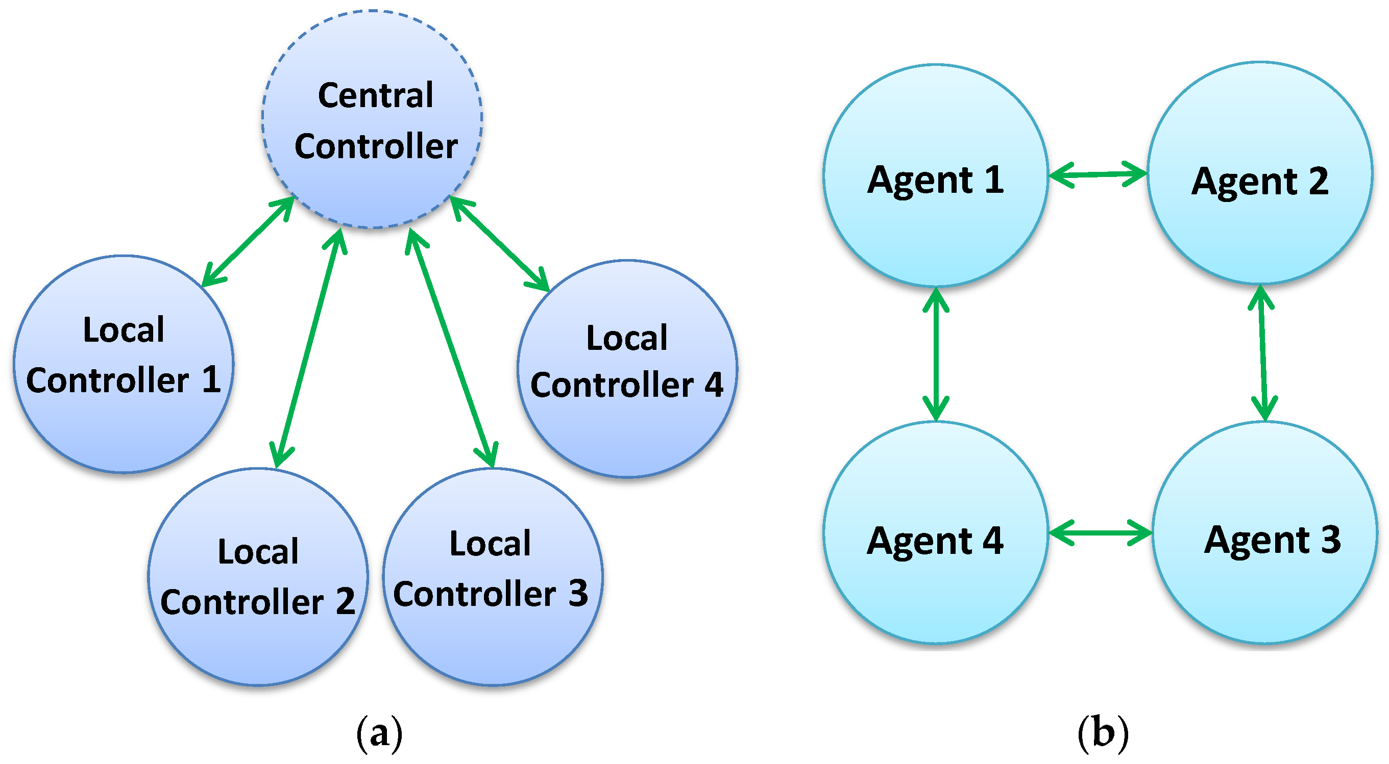
The different communication topologies between the conventional centralized method and the consensus-based multiagent system are illustrated in
Figure 7. In this example, it assumes that there are four DG units in the microgrid.
Figure 7b only shows one possibility of the communication topology of the multiagent system, in which no centralized controller is needed and each local agent communicates with their neighbouring agents in a connected graph.
Here, a graph G will be used to model the communication network of the multiagent system. Let G = (V, E) be a undirected graph with a set of vertices V = {1, 2, … , n} and a set of edges E ⊆ V × V. The undirected edge connects i and j is denoted by an unordered and distinct pair (i,j) ∈ E. The neighbours of vertices i is denoted as by Ni = {j ∈ V|(i,j) ∈ E}. An undirected graph is called connected if and only if there exists a path between any distinct pair of two vertices.
In the communication network of multiagent system, each agent can be represented by a vertex, and the edge between any pair of two different agents means the bidirectional communication link between this pair of agents. The basis updating process of agent
i can be written as:
where
is the consensus variable discovered by agent
j at iteration
t,
is the consensus variable discovered by agent
j at iteration
t + 1, and
dij is the coefficient associated with edge
ij. The coefficients need to be designed in the algorithm to make consensus converge.
There are several methods to determine the coefficients
dij [
24,
31,
32,
33], e.g., the Perron matrix [
31], the uniform method [
32], or the metropolis method [
24,
33], where
D is the coefficients matrix of the communication system, and to guarantee the convergence of the system,
D should satisfy the following two constraints:
- (1)
D is the double-stochastic matrix, i.e., the sum of D’s row and columns are both ones;
- (2)
The eigenvalues of D should be within a close disk |λi| ≤ 1.
Here the same method used by [
24] is chosen in this paper to be adaptive to changes of communication topology and guarantee good convergence speed. The coefficients are defined as:
where
is the number of neighbours of vertices
i.
The updating rule of the proposed incremental consensus algorithm is designed as follows:
where
is the incremental cost of agent
i at the iteration
t, ε is the feedback coefficients which controls the convergence of the consensus, and
is the estimation of the global supply-demand mismatch.
The initialization of the system can be set as follows:
3.5. Convergence Analysis of the Incremental Cost Consensus
In order to analyse the convergence of the designed consensus algorithm, the updating rule of each agent in Equations (21)–(24) can be rewritten in the following matrix form:
where
,
, and
are the column vectors of r
i, P
D,
i and P
G,
i; and
Q is the column of
, and
H = diag ([1/2α1, 1/2α2, …,1/2α
n]).
The updating rule can be further reduced to:
where I
n is a
identity matrix, since ε is very small, it can be neglected, so that we can make the following approximation:
Therefore, the eigenvalues of
M are the same as those of D. As D is designed as Equation (9), it can be verified that
M has
when
, that is:
As it is proved in [
12], this property of
M means that the system of Equation (18) will converge to span
with infinite number of iterations, that is:
Premultiplying
to both sides of Equation (28), it yields:
Since
, then:
Considering Equation (11), there is:
The incremental cost will finally converge to Equation (18).
3.6. Convergence Dynamics
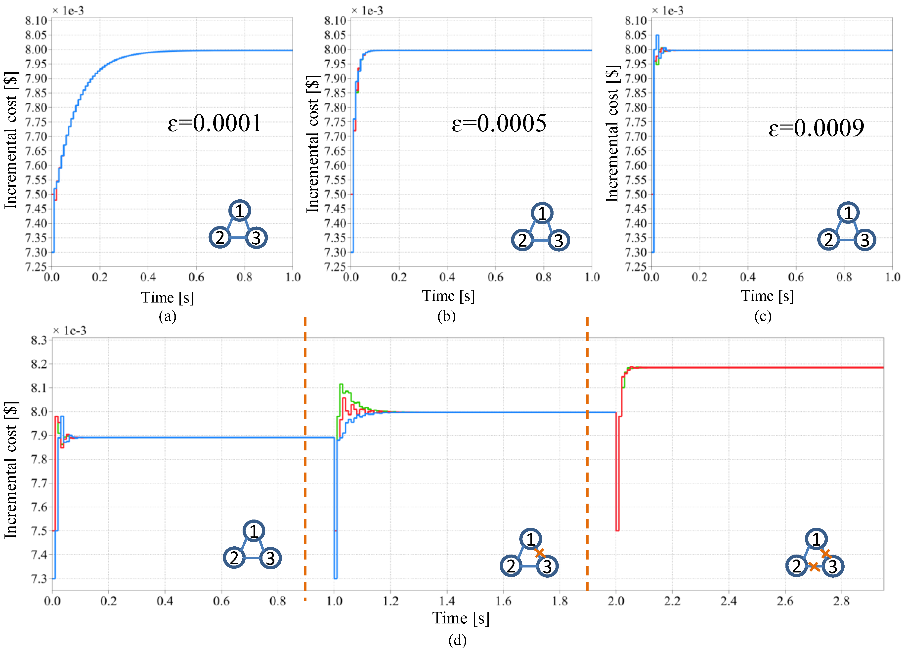
In order to pre-test the proposed consensus algorithm and to investigate the impact of control parameters and topology on the convergence, a simulation study is conducted with three units under different scenarios. The cost function coefficients of the three units are listed in
Table 1. The sampling time of the communication layer is 0.01 s. The impact of the feedback coefficients is firstly investigated. As can been seen from
Figure 8a–c, as this parameter gets larger, the speed of convergence increases. However, with too large a parameter value, there will be an overshoot in the convergence process. Moreover, the robustness to the communication topology change is tested. At the beginning, these three units communicate with their neighbours in a circle. After 1 s, the link between unit 1 and unit 3 is lost. Then, after 2 s, the link between unit 2 and unit 3 is also lost, and unit 3 is disconnected from the system. As can be seen in
Figure 8d, the loss of one communication link doesn’t stop the system from convergeing to the common incremental cost, but only the speed of the convergence is compromised since the communication topology is still a connected graph. After the unit 3 is disconnected from the system, under the new communication topology, unit 1 and unit 2 converge to a new value, which shows the effectiveness of the algorithm under the topology changes.
3.7. Multiagent System Implementation
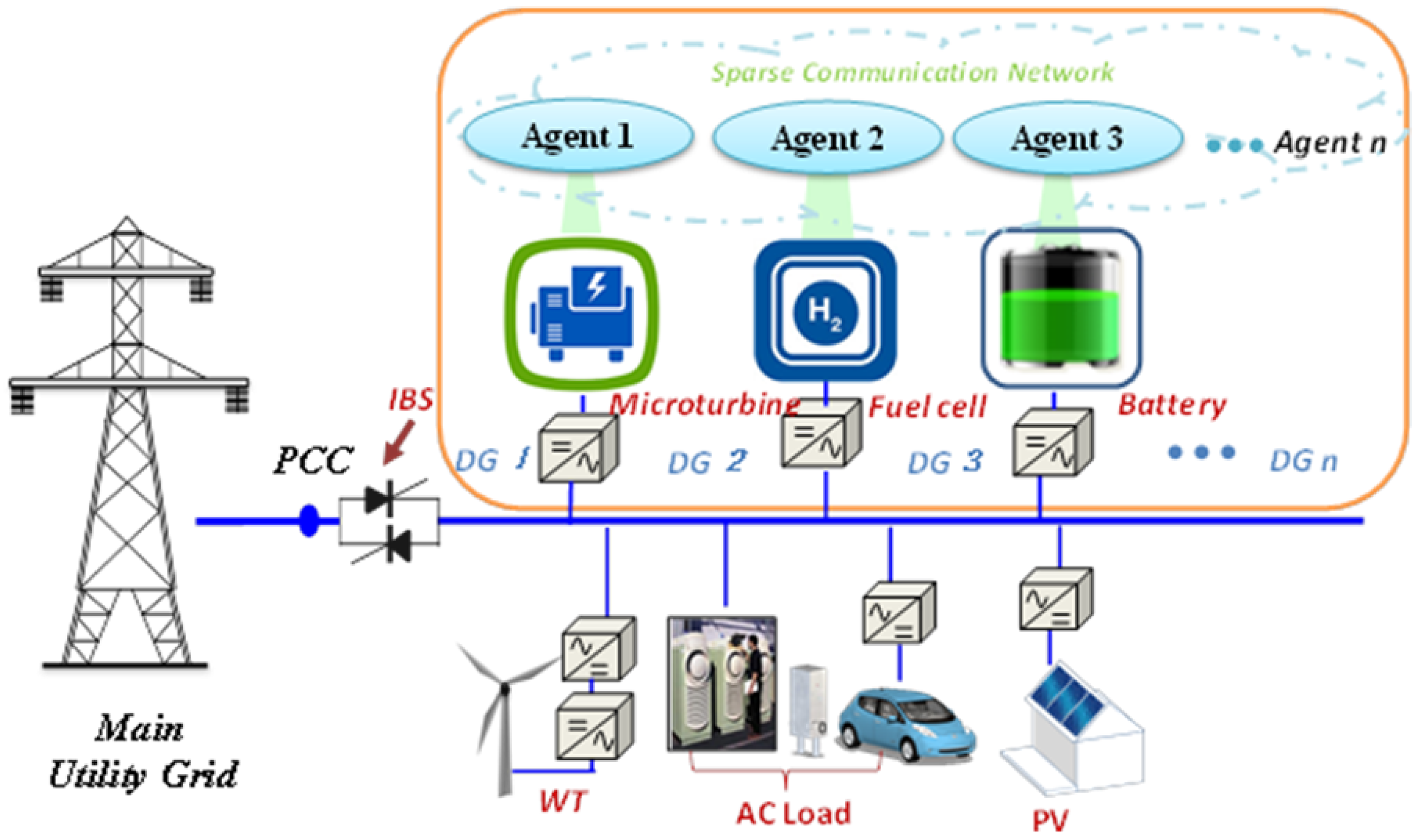
An example of microgrids is shown in
Figure 9. The microgrid is composed of different kinds of generators and various load. Since normally we configure the renewable in MPPT mode as current source converter and thus only other backup generators which are dispatchable are considered for optimization. Each dispatchable generator is controlled by an agent, and all the agents can exchange the information through a sparse communication network with a connected graph topology.
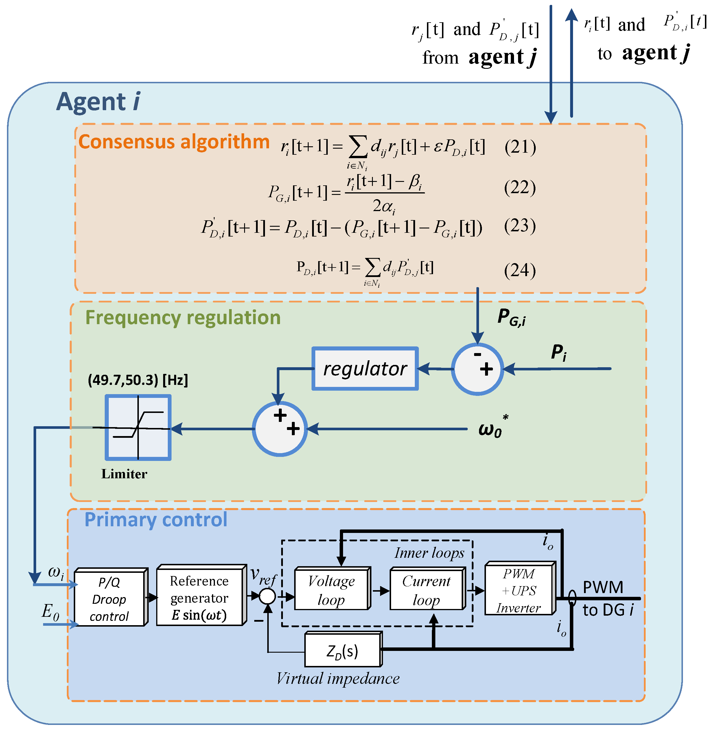
The implementation of the multiagent system is a distributed control in which each agent has an identical local control. The local control in a hierarchical structure from bottom to top consists of primary control, frequency regulation for power control, and consensus algorithm for optimal dispatch. The structure is shown in
Figure 10.
In the primary level, droop control is adopted to share the power autonomously. To regulate the real power, the nominal frequency is changed according to the mismatch of the actual power generation and the optimal power command. The optimal power command is obtained through the distributed incremental consensus algorithm.


 ,
, 


