Study on the Shielding Effectiveness of an Arc Thermal Metal Spraying Method against an Electromagnetic Pulse
by
 and
and
Han-Seung Lee
1, 
Hong-Bok Choe
1,
In-Young Baek
1,
Jitendra Kumar Singh
1 and
Mohamed A. Ismail
2,* 1
Department of Architectural Engineering, Hanyang University, 1271 Sa 3-dong, Sangrok-gu, Ansan 426-791, Korea
2
Department of Civil and Construction Engineering, Faculty of Engineering and Science, Curtin University Malaysia, Miri 98009, Malaysia
*
Author to whom correspondence should be addressed.
Materials 2017, 10(10), 1155; https://doi.org/10.3390/ma10101155
Submission received: 4 September 2017
/
Revised: 24 September 2017
/
Accepted: 28 September 2017
/
Published: 4 October 2017
Abstract
:An electromagnetic pulse (EMP) explodes in real-time and causes critical damage within a short period to not only electric devices, but also to national infrastructures. In terms of EMP shielding rooms, metal plate has been used due to its excellent shielding effectiveness (SE). However, it has difficulties in manufacturing, as the fabrication of welded parts of metal plates and the cost of construction are non-economical. The objective of this study is to examine the applicability of the arc thermal metal spraying (ATMS) method as a new EMP shielding method to replace metal plate. The experimental parameters, metal types (Cu, Zn-Al), and coating thickness (100–700 μm) used for the ATMS method were considered. As an experiment, a SE test against an EMP in the range of 103 to 1010 Hz was conducted. Results showed that the ATMS coating with Zn-Al had similar shielding performance in comparison with metal plate. In conclusion, the ATMS method is judged to have a high possibility of actual application as a new EMP shielding material.
1. Introduction
An electromagnetic pulse (EMP), generated by a nuclear explosion, can neutralize electronic and communication devices instantly within a wide radius, approximately up to 1500 km. When the EMP arrives at the ground surface, it creates a very strong induced current, which enters electronic circuits and destroys them by means of overcurrent that the circuit cannot resist [1,2]. It is such as a high-output energy bomb, which consists of an electromagnetic wave (=electronic wave) and explodes at the range of 40–400 km altitudes [1,2]. In addition, it is able to produce 50–100 kV/m of electric field intensity at its maximum. Considering that the receiving electric field intensity of a general radio transceiver is just several mV, it can be seen that EMP has a very strong amount of electromagnetic energy [2]. In addition, the frequency range of an EMP is from about 100 kHz–100 MHz. This means that an EMP can influence and damage the operational frequency ranges of civilian and military electronic equipment [3].
From the point of military defense, an EMP can cause neutralization and risk of national and international infrastructure facilities, such as the electrical grid and the communication network [4]. Moreover, it can cause severe damage to confidential military intelligence systems by paralyzing military communication equipment [5]. Therefore, it is highly recommended to develop EMP shielding methods to minimize the damage.
The EMP, or electromagnetic interference (EMI), can be reduced using different conducting, flexible, ductile, composite, and novel materials [6,7,8,9,10,11]. The SE of these composite materials depend on intrinsic conductivity, aspect ratio, and content of the fillers [12,13]. These properties of materials can be improved by adding conducting elements, such as carbon nanotubes, graphene, etc. [14]. The conducting polymer is a promising material to be used to increase the SE of composite materials in high-frequency ranges [15,16,17]. However, in spite of the advantage of these materials, it cannot be used as SE materials against an EMP due to some disadvantages, such as high cost, impurities from the catalysts, bundling, and aggregation [18].
Conventional EMP shielding facilities for floor systems can be explained through Figure 1. EMP shielding methods are divided largely into two parts. One is a shielding plate at the door, which consists of a shielding room. A shielding room is a place where electronic equipment is installed for their protection. Another is an EMP filter and honeycomb, a method to shield the point of entry (POE) of an EMP in the shielding room. POE is a hole that is inevitably made when communication equipment and heating, ventilation and air conditioning (HVAC) are brought into the shielding room [19].
In previous studies, the main research of EMP shielding methods were with respect to shielding effectiveness (SE) of concrete structures, EMP filters, and honeycomb [20,21,22,23]. Concrete structures are the basic frame of EMP shielding facilities to protect the shielding room from being destroyed by external physical influence. In general, when the concrete structure is constructed, a shielding room in manufactured by metal plates placed on the inside of the concrete structure.
On the other hand, the study on shielding plate has not actively proceeded [24,25]. Conventionally, metal plate has been mainly used as shielding plate due to its excellent SE against an EMP. For the construction of the shielding room, metal plates are welded or assembled by bolts to each other. However, this method has shown a difficulty in manufacturing as follows: a possibility of EMP inflow through welded parts, and expensive construction costs [26]. To solve this problem, developing a new EMP shielding method to replace the metal plate is required.
The objective of this study is to examine an applicability of the arc thermal metal spraying method (ATMS method), as a new EMP shielding method replacing conventional metal plate. The ATMS method has several properties that can perform as a shielding material. For example, this method can shield electromagnetic waves, form a shielding coating easily, and control the coating thickness flexibly. In addition, it can be applied to any substrate under the condition that the substrate surface is treated to have roughness. Thus, there is no need to install a shielding room. The ATMS method can be applied directly to a concrete wall. It is expected to reduce much of the construction cost for EMP-shielded rooms.
The principle of the arc ATMS method is described elsewhere [27,28,29,30,31,32]. However, the ATMS method is an anti-corrosion method that forms a metal coating on a steel structure by using a metal wire mesh, such as Zn and Al. The process is as follows: first, two metal wires are supplied into the driving device, which plays the role of an arc spray gun. Second, through a linear element guide nozzle, those wires are shifted and melted at the arc point. By compressed air, the melted metal particles are sprayed to the outside entraining cooling action and attached to the surface of the substrate. These attached metal particles, by continued accumulation and consolidation, finally form a porous and compact metal coating (arc thermal metal spray coating; hereafter, ATMS coating). During this process, when metal particles contact the surface of the substrate, it is quickly cooled to almost room temperature due to compressed air. Since the ATMS coating is formed at room temperature, the substrate does not generate any thermal strain. Finally, a solid and stable ATMS coating is formed [33,34].
There are two reasons why the ATMS method is expected to show suitable properties as an EMP shielding method. First, because it uses a metallic material the same as metal plate, it would show a SE against EMP as well. Second, because it is a coating method to prevent corrosion of the steel structure, the ATMS coating is resistant to chloride or moist environments. When the coating is exposed for a long period under a corrosive environment, it creates an oxide coating on itself and becomes more compact [35]. In some cases, for the purpose of military defense, EMP shielding facilities are constructed underground. Such an environment is vulnerable to corrosion. Thus, the ATMS method can combine the anti-corrosion effect and the EMP shielding effectiveness together.
The shielding process to reduce the EMP impact on the surface is described in Supplementary Figure S1. This figure indicates the shielding principle of metallic material against electromagnetic waves. In the conventional method, the entire shielding room is constructed with metal plate (galvanized steel, copper, iron, etc.), about 2–5 mm in thickness. This is because the metallic material shows excellent SE against electromagnetic waves.
This attenuates the inflow of the electromagnetic wave by three mechanisms. First, it is the reflection loss, generated by impedance mismatching between air layer and metal. Most of electromagnetic wave is shielded by the reflection loss. Second, it is the penetration loss, generated in the form of heat dispersion caused by the ohmic loss, when the electromagnetic wave penetrates into the metal shielding plate. Finally, it is the multi-reflection loss, generated by the second reflection inside the inner metal layer. This happens at the boundary layer of both sides of the metal shielding plate [36].
Therefore, it can be seen that metallic materials are effective as EMP shielding materials. However, the SE of metallic materials varies depending on the coating conditions or type of metal. In general, a metallic material that shows low impedance with electrical conductivity and a metal with no holes or cracks can improve the SE to prevent inflow of high-frequency electromagnetic waves.
For the purpose of this study, a SE test against an EMP was carried out to compare the shielding performance between the ATMS coating and metal plate.
2. Experimental Details
2.1. Experimental Variables
Table 1 indicates the experimental variables for the evaluation on the SE against EMP. In this experiment, the type of metal used as the shielding material and the thickness of ATMS coating were selected to be tested. In case of EMP shielding material, Fe and Cu were selected for the metal plate and Cu and Zn-Al were selected for the ATMS method. The mesh of wires chosen for the deposition of the coating was 2.4 mm. In the case of the thickness of the ATMS coating, 100, 300, 500, and 700 μm were selected with consideration of the application efficiency. The coating thickness was measured at three different locations of each coating and error is shown in Figure S2. The error was a maximum of ±5% for each coating thickness.
2.2. Test Specimens for Experiments
Table 2 indicates the list of specimens used for the SE test. Specimen 1 is a tempered glass, which is a substrate for ATMS coating. Glass is known as having no SE against electromagnetic waves. For that reason, it was used to measure a SE of the ATMS coating by itself. In addition, because the substrate required enough durability when blasting on the surface is treated, the tempered glass was expected to perform as an appropriate material as a substrate. A thickness of 6 mm was used in this experiment and the surface was sand-blasted to secure adhesiveness between the ATMS coating and the tempered glass. Specimens 2 and 3 are Fe and Cu metal plate, which are widely used as EMP shielding materials. Specimens 4–11 are specimens that were prepared by the ATMS method. ATMS coating by Cu was selected for a comparison of SE with the conventional metal plate by Cu. ATMS coating by Zn-Al was selected because it has been widely used as the spraying metal type in the ATMS method. Thickenesses of 100, 300, 500, and 700 μm of the ATMS coating were selected. When the ATMS method was applied, in the case an ATMS coating over 700 μm thickness is formed at one cycle, there was a limitation of adhesiveness between ATMS coating and tempered glass because of the thermal strain of the ATMS coating itself. For that reason, the maximum thickness was set to 700 μm. Metal plates with a thickness of 3 cm were selected, considered to be commonly used in the construction of the shielding room.
2.3. Experimental Procedures
Figure 2 indicates the whole process of the experiment. First, the tempered glass was prepared with sand-blasting, as shown in Figure 2a. Second, ATMS coating was applied, as shown in Figure 2b. Figure 2c is the case of applying Zn-Al and Figure 2d is the case of applying Cu (colored in red). Third, calibration of the electromagnetic wave transmitter and receiver was conducted, as shown in Figure 2e. Finally, the gasket installation, EMP shielding wall outside and inside, and SE test is shown in Figure 2f–i, respectively.
2.4. Standards on Shielding Effectiveness against EMP and SE Tests
Figure S3 indicates the required SE against EMP of shielding material for each frequency range when constructing the EMP shielding room. The specification in this criteria follows IEEE-STD-299, be the Institute of Electrical Engineers (IEEE); MIL-STD-188-125-1, a common specification of the US Ministry of Defense; and DMFC 4-70-30, a design standard for electromagnetic wave defense facilities that is based on the criteria of national defense and military facilities.
The required minimum SE value ranges from 103 to 1.5 × 10⁹ Hz as shown in Figure S3 [37,38]. In the magnetic area, the frequency range is from 103 to 2 × 10⁷ Hz (=1 kHz to 20 MHz). The required SE increases proportionately as the frequency increases. For the resonant range and plane wave area, the frequency range is from 2 × 10⁷ to 109 Hz (=20 MHz to 1 GHz). In this range, over 80 dB SE is required regardless of the frequency change. The unit of SE is dB (decibel) and this represents the attenuation amount of electromagnetic wave by the shielding material.
Equation (1) indicates the calculation on SE against EMP of the shielding materials in a SE test. This is to confirm the SE of the shielding materials against an emitted electromagnetic wave. It represents the ratio of received amount when there is no shielding material (Vc) to the received amount with a shielding material (Vm) [39].
Shielding Effectiveness (SE) = 20 log (Vc/Vm) (dB)
Figure S4 shows the schematic diagram of the SE test for this experiment. In general, as shown in Figure S4, the SE test is conducted by installing the electromagnetic wave transceiver at the inside and outside of the EMP shielding wall. Prior to the test, the EMP shielding room was manufactured and completely closed without any open space.
In this experiment, for the accurate measurement of specimens, an area of 300 × 300 mm2 was cut out from the shielding wall and the specimen was fixed into void part. The reason is to allow the electromagnetic wave would be transmitted only within the specimen area upon emission of the electromagnetic wave. If a size of a void part was smaller than 300 × 300 mm2, there would be a possibility that a wave could pass the shielding wall surface. In the case of the specimen size, an area of 450 × 450 mm2 was prepared. In addition, the calibration work was conducted by emitting an electromagnetic wave in a state that there would be no specimen on the wall. The purpose was to adjust the transmission and reception error rates in the generator before the SE test.
Figure S5 indicates the cross-sectional diagram of SE test for the installation of specimens. In order to fix the specimen above the shielding wall, a specimen fixation plate was installed at the inside and outside of the shielding wall with bolts. This was to prevent the specimen from moving. After the fixation, the experiment was carried out.
Table S1 indicates the frequency range of transmitted electromagnetic wave in SE test. The test frequency range was selected based on the IEC 61000-4-23 of IEC (International Electronic Committee) regulations, MIL-STD-188-125-1, and IEEE-STD-299 [37,38].
By referring to the required SE as shown in Table S1, specimens 1–3 correspond to the magnetic area (103–2 × 10⁷ Hz), specimens 4 and 5 correspond to the resonant range and plane wave area (2 × 10⁷–109 Hz), and specimens 6 and 7 correspond to the plane wave area (109–1.5 × 10⁹ Hz). Although there were differences in the number of measurements depending on the regulation, in order to secure the reliability of the measurement results, the average value was extracted after three measurements per each frequency range.
3. Results and Discussions
3.1. Shielding Effectiveness of Tempered Glass
Table 3, Table 4 and Table 5 indicate the results of SE test of each specimen depending on the frequency range. Table 3 indicates the results of tempered glass and metal plates. Table 4 indicates the results of ATMS coatings by Zn-Al depending on its thickness. Table 5 shows the results of ATMS coatings by Cu depending on its thickness.
In case of tempered glass, it was found that the average SE was 0.9 dB due to more brittleness than metallic and composite materials. Therefore, the tempered glass exhibits lower SE values than others. Based on this result, it can be seen that the tempered glass had little influence on the SE of the ATMS coating.
3.2. Shielding Effectiveness of Metal Plate
For the sake of clarity, SE values are explained in Figure 3, which represents the test results of Plate-Fe and Plate-Cu. It was found that both Plate-Fe and Plate-Cu satisfied the minimum SE throughout the entire frequency range. Plate-Fe showed and average of 97.7 dB SE and Plate-Cu showed average 103.6 dB SE (Table 3). Based on the comparison of the SE with regards to metal type, Cu showed about 5.98% better SE than Fe on average throughout all studied frequency ranges (Figure 3). Thus, as an EMP shielding material, Cu showed better SE than Fe and this might be due to the conductivity and mechanical properties, which affects the SE values [40]. The required SE values against each studied frequency are shown by a red line in Figure 3.
3.3. Shielding Effectiveness of ATMS Coating
Figure 4 indicates the SE test results of MS-Zn-Al specimens with different coating thicknesses. It was found that all specimens satisfied the required minimum SE value, regardless of the coating thickness. Even with only 100 μm thickness, the minimum thickness which ATMS coating is applied, it showed an average of 9% higher SE than the required minimum SE values. The test results, with regards to coating thickness, showed a tendency that there was an increase of SE with an increase of thickness (14–16 kHz, 140–160 kHz, 0.85–1 GHz, and 8.5–10.5 GHz range). On the other hand, there was also a decrease in SE with an increase of thickness (14–16 MHz, 300–400 MHz, and 16–18 GHz range). This means that thickness is not necessarily relevant to the improvement of SE, in the range of μm thickness.
The symbol on bars of Figure 5, i.e., (+) represents the increase of shielding rate while (−) represents the decrease of shielding rate on average variation rate (%) of Zn-Al specimens. As a result, it showed that the maximum increase rate on average was about +9% (14–16 KHz) and the decrease rate on average was about −4.18% (300–400 MHz). On average, the variation rate throughout entire frequency range showed about +1.2% increase. It can be analyzed that ATMSM formed a stable Zn-Al coating that is able to shield any electromagnetic wave properly. Thus, it is judged that the thickness of ATMS coating by Zn-Al does not cause a big difference, as EMP shielding material. It showed consistent SE value regardless of thickness.
Figure 6 shows the SE test results of MS-Cu. It was found that the ATMS coatings by Cu also satisfied the required minimum SE value, regardless of the thickness. However, differently from the test result by Zn-Al coating, there is, mainly, a decrease of SE with an increase in thickness. In addition, the variation rate fluctuated more than that of the Zn-Al coating. It seems that ATMSM forms a relatively unstable Cu coating. This can provide an unsatisfying SE value according to the standards.
The MS-Zn-Al 100 and MS-Cu 100 specimens performed better than other thicknesses of coatings; therefore, the SE test results of these two coatings are shown in Figure 6. As a result, MS-Zn-Al 100 showed higher SE than MS-Cu 100 from minimum +17.3% (300–400 MHz range) to maximum +44.9% (0.85–1 GHz). This result indicates that ATMS coatings by Zn-Al have about 30% higher SE, on average, than the ATMS-Cu coating in terms of the entire frequency range. It is judged that this is because the density of the Zn-Al coating was more compact than that of the Cu.
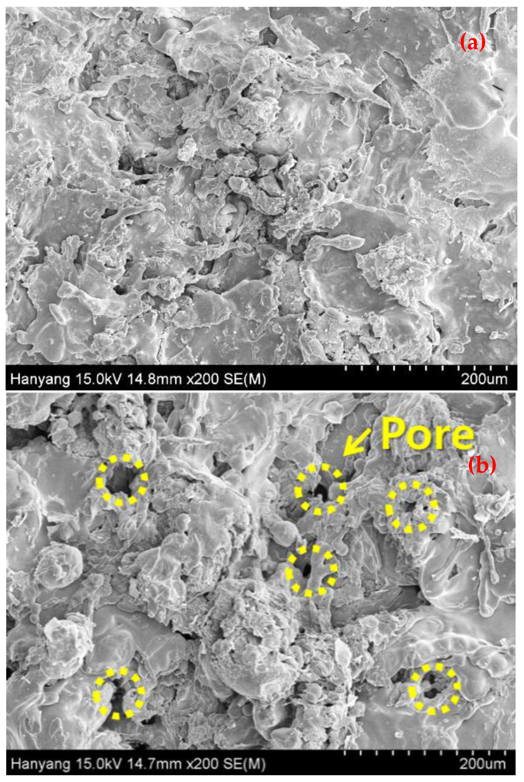
To corroborate the above findings, scanning electron microscopy (SEM, Philips XL 30, North Billerica, MA, USA) results of MS-Zn-Al 100 and MS-Cu 100 are shown in Figure 7. When the ATMS method is applied on the substrate, the metal particles form a coating in a gelatinous state, which is between a liquid and solid state. In this process, a metal that has a lower melting temperature easily forms this gelatinous state and the ATMS coating accumulates more densely [34]. The melting temperatures of Zn, Cu, and Al, are 419.53 °C, 1084.62 °C, and 660.32 °C, respectively. The surface of MS-Zn-Al 100 in Figure 7a was formed with lesser pores and more densely than that of MS-Cu 100 in Figure 7b. When applying Cu as ATMS coating, it was shown that Cu did not form a dense coating on the substrate rather it forms more pores/cracks on top surface evident from Figure 7b. In addition, it created many pores between metal particles. The reason is that Cu was not easy to change its particle in a gelatinous state than Zn or Al due to its higher melting point. This result indicates that there is more possibility for electromagnetic wave to penetrate the Cu coating through the connected pores in actual EMP occurrence. When the principle on shielding effectiveness by metallic material was explained, it was mentioned that a metal layer with no hole or crack can improve SE against electromagnetic wave. From the analysis, SE test result shown in Figure 5 can be explained why ATMS coating by Cu showed unstable SE value. In spite of increased coating thickness, due to the formation of many pores in the coating, it could not show consistent SE against electromagnetic waves. Thus, it is judged that when applying the ATMS method as the EMP shielding material, Zn-Al can better SE than Cu.
3.4. Shielding Effectiveness between Metal Plate and ATMS Coating
Figure 8 indicates the SE test results of metal plate (plate-Cu) and ATMS coating by Cu (MS-Cu 100). It shows that MS-Cu 100 has a lower SE than plate-Cu, from a minimum of −13.54% (14–16 MHz) to a maximum of −48.9% (14–16 kHz) and, on average, −27.76% for the entire frequency range. From the results in Figure 4 and Figure 5, it was found that the SE of metallic materials was not largely influenced by the coating thickness. Thus, it is judged that the lower SE value of MS-Cu 100 than plate-Cu is due to the large number of pores in MS-Cu 100. Based on this result, it is thought that Cu is not a suitable replaceable material for the metal plate when applying the ATMS method.
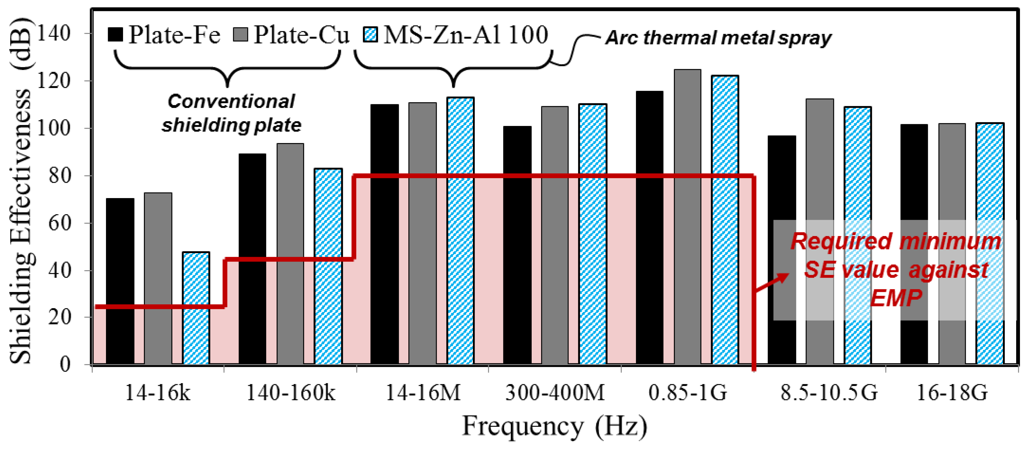
Figure 9 indicates SE test results of Plate-Fe and Plate-Cu, which are metal plates, and ATMS coating by Zn-Al (MS-Zn-Al 100). As a comparison of SE between MS-Zn-Al 100 and metal plates, MS-Zn-Al 100 showed a lower SE in the low-frequency range (14–16 kHz, 140–160 kHz) than metal plates. However, in the other frequency ranges (14–16 MHz, 300–400 MHz, 0.85–1 GHz, 8.5–10.5 GHz, 16–18 GHz), MS-Zn-Al 100 showed similar or more improved SE than metal plates. Based on these results, it is judged that the ATMS method by Zn-Al has high possibility on actual application, instead of conventional EMP shielding plate.
4. Conclusions
This study evaluated the shielding effectiveness against EMP of the ATMS method in order to investigate the applicability of ATMS coating as a replacement material for conventional EMP shielding plate. As a SE test result, ATMS coating by Zn-Al satisfied the required SE according to the standards. In addition, it showed similar shielding performance in comparison with metal plate. Therefore, it is judged that ATMS coating has a high probability of actual application as a new EMP shielding material.
Supplementary Materials
The following are available online at https://www.mdpi.com/1996-1944/10/10/1155/s1, Figure S1: Shielding principle of metal material against electromagnetic wave, Figure S2: Coating thickness and error bar of Zn-Al and Cu coating, Figure S3: The required shielding effectiveness in terms of EMP shielding room, Figure S4: Schematic diagram of SE test for specimens, Figure S5: Cross-sectional diagram of SE test for installation of specimens, Table S1: Frequency range of SE test.
Acknowledgments
This research was supported by Basic Science Research Program through the National Research Foundation of Korea (NRF) funded by the Ministry of Science, ICT, and Future Planning (No. 2015R1A5A1037548).
Author Contributions
H.S.L. has designed the work while H.B.C. and I.Y.B. performed the experiments. Analysis of results have been performed by H.S.L., H.B.C., and I.Y.B. The initial draft of the manuscript was prepared by H.S.L., H.B.C., and M.A.I. J.K.S. and M.A.I. have written the final draft of the manuscript. All authors have contributed equally to the final manuscript.
Conflicts of Interest
The authors declare no conflict of interest.
References
- Kim, H. Truth of EMP threat and development plan. DefenseTech 2013, 414, 98–103. (In Korean) [Google Scholar]
- Choi, T.; Cho, W. Countermeasure of Electromagnetic Pulse (EMP). DefenseTech 1992, 157, 54–59. (In Korean) [Google Scholar]
- Cho, G.; Cheon, J. Study on defense measure of EMP of nuclear and electromagnetic pulse weapon. DefenseTech 2007, 345, 52–59. (In Korean) [Google Scholar]
- Jacob, G. The Swiss EMP Concept of General Defense. IEEE Antennas Propag. Soc. Newsl. 1987, 29, 5–10. [Google Scholar]
- Fugetsu, B.; Sano, E.; Sunada, M.; Sambongi, Y.; Shibuya, T.; Wang, X.; Hiraki, T. Electrical conductivity and electromagnetic interference shielding efficiency of carbon nanotube/cellulose composite paper. Carbon 2008, 46, 1256–1258. [Google Scholar] [CrossRef]
- Kim, H.M.; Kim, K.; Lee, C.Y.; Joo, J.; Cho, S.J.; Yoon, H.S.; Pejakovic, D.A.; Yoo, J.W.; Epstein, A. Electrical conductivity and electromagnetic interference shielding of multiwalled carbon nanotube composites containing Fe catalyst. J. Appl. Phys. Lett. 2004, 84, 589–591. [Google Scholar] [CrossRef]
- Li, N.; Huang, Y.; Du, F.; He, X.B.; Lin, X.; Gao, H.J.; Ma, Y.F.; Li, F.F.; Chen, Y.S.; Eklund, P.C. Electromagnetic Interference (EMI) Shielding of Single-Walled Carbon Nanotube Epoxy Composites. Nano Lett. 2006, 6, 1141–1145. [Google Scholar] [CrossRef] [PubMed]
- Al-Saleh, M.H.; Sundararaj, U. Electromagnetic interference shielding mechanisms of CNT/polymer composites. Carbon 2009, 47, 1738–1746. [Google Scholar] [CrossRef]
- Liang, J.J.; Huang, Y.; Zhang, L.; Wang, Y.; Ma, Y.F.; Guo, T.Y.; Chen, Y.S. Molecular-Level Dispersion of Graphene into Poly(vinyl alcohol) and Effective Reinforcement of their Nanocomposites. Adv. Funct. Mater. 2009, 19, 2297–2302. [Google Scholar] [CrossRef]
- Thomassin, J.M.; Pagnoulle, C.; Bednarz, L.; Huynen, I.; Jerome, R.; Detrembleur, C.J. Foams of polycaprolactone/MWNT nanocomposites for efficient EMI reduction. Mater. Chem. 2008, 18, 792–796. [Google Scholar] [CrossRef]
- Park, S.H.; Theilmann, P.; Yang, K.Q.; Rao, A.M.; Bandaru, P.R. The influence of coiled nanostructure on the enhancement of dielectric constants and electromagnetic shielding efficiency in polymer composites. Appl. Phys. Lett. 2010, 96, 043115. [Google Scholar] [CrossRef]
- Zhang, H.B.; Zheng, W.G.; Yan, Q.; Yang, Y.; Lu, Z.H.; Wang, J.W.; Ji, G.Y.; Yu, Z.Z. Electrically conductive polyethylene terephthalate/graphene nanocomposites prepared by melt compounding. Polymer 2010, 51, 1191–1196. [Google Scholar] [CrossRef]
- Xie, S.H.; Liu, Y.Y.; Li, J.Y. Comparison of the effective conductivity between composites reinforced by graphene nanosheets and carbon nanotubes. Appl. Phys. Lett. 2008, 92, 243121. [Google Scholar] [CrossRef]
- Xu, X.B.; Li, Z.M.; Shi, L.; Bian, X.C.; Xiang, Z.D. Ultralight Conductive Carbon-Nanotube–Polymer Composite. Small 2007, 3, 408–411. [Google Scholar] [CrossRef] [PubMed]
- Yang, Y.L.; Gupta, M.C. Novel Carbon Nanotube−Polystyrene Foam Composites for Electromagnetic Interference Shielding. Nano Lett. 2005, 5, 2131–2134. [Google Scholar] [CrossRef] [PubMed]
- Yang, Y.L.; Gupta, M.C.; Dudley, K.L.; Lawrence, R.W. Conductive carbon nano fiber polymer foam structures. Adv. Mater. 2005, 17, 1999–2003. [Google Scholar] [CrossRef]
- Zhang, H.-B.; Yan, Q.; Zheng, W.-G.; He, Z.; Yu, Z.-Z. Tough Graphene-Polymer Microcellular Foams for Electromagnetic Interference Shielding. ACS Appl. Mater. Interfaces 2011, 3, 918–924. [Google Scholar] [CrossRef] [PubMed]
- Esawi, A.M.K.; Farag, M.M. Carbon nanotube reinforced composites: Potential and current challenges. Mater. Des. 2007, 28, 2394–2401. [Google Scholar] [CrossRef]
- Lee, W. Defense measure of EMP and required technique. Proc. Korea Electromagnet. Eng. Sci. 2013, 24, 79–96. (In Korean) [Google Scholar]
- Fei, G.; Bihua, Z.; Cheng, G.; Hailin, C. Analysis of shielding effectiveness of conductive cement-based materials in HEMP environment. In Proceedings of the 2008 International Conference on Microwave and Millimeter Wave Technology (ICMMT 2008), Nanjing, China, 21–24 April 2008; Available online: http://ieeexplore.ieee.org/stamp/stamp.jsp?arnumber=4540721 (accessed on 10 March 2015).
- Fei, G.; Bihua, Z. Analysis of shielding effectiveness of monolayer and double layer cement shield rooms to HEMP. In Proceedings of the 2008 China-Japan Joint Microwave Conference, Shanghai, China, 10–12 September 2008; pp. 505–508. [Google Scholar]
- Hyun, S.Y.; Du, J.K.; Lee, H.J.; Lee, K.W.; Lee, J.H.; Jung, C.S.; Kim, E.J.; Kim, W.D.; Yook, J.G. Analysis of shielding effectiveness of reinforced concrete against high-altitude electromagnetic pulse. IEEE. Trans. Electromagn. Compat. 2014, 56, 1488–1496. [Google Scholar] [CrossRef]
- Bin, C.; Yun, Yi.; Cheng, G.; Bihua, Z.; Wei, W. Analysis of shielding effectiveness of reinforced concrete in high power electromagnetic environment. In Proceedings of the 2003 Asia-Pacific Conference on Environmental Electromagnetics (CEEM 2003), Hangzhou, China, 4–7 November 2003; pp. 547–553. Available online: http://ieeexplore.ieee.org/stamp/stamp.jsp?arnumber=1282391 (accessed on 11 Sepetember 2016).
- Nenghong, X.; Xueqin, Y.; Wenwu, S. Shielding effectiveness and coupling characteristic of metallic enclosures with apertures under EMP. In Proceedings of the 2009 Asia-Pacific Power and Energy Engineering Conference (APPEEC 2009), Wuhan, China, 27–31 March 2009; pp. 1–4. Available online: http://ieeexplore.ieee.org/stamp/stamp.jsp?arnumber=4918742 (accessed on 25 June 2017).
- Cheng, G.; Bihua, Z.; Bin, C.; Yun, Y.; Yanxin, L. The penetrating of EMP fields into a metal shielding enclosure by a slot. In Proceedings of the 2002 3rd International Symposium on Electromagnetic Compatibility, Beijing, China, 21–24 May 2002; pp. 127–130. Available online: http://ieeexplore.ieee.org/stamp/stamp.jsp?arnumber=1177382 (accessed on 1 July 2017).
- Seo, M.J.; Chi, S.W.; Kim, Y.J.; Park, W.C.; Kang, H.J.; Huh, C.S. Electromagnetic wave shielding effectiveness measurement method of EMP protection facility. J. Korea Inst. Electromagnet. Eng. Sci. 2014, 25, 548–558. (In Korean) [Google Scholar] [CrossRef]
- Pawlowski, L. The Science and Engineering of Thermal Spray Coatings, 2nd ed.; John Wiley & Sons Ltd.: West Sussex, UK, 2008. [Google Scholar]
- Lee, H.-S.; Singh, J.K.; Ismail, M.A.; Bhattacharya, C. Corrosion resistance properties of aluminum coating applied by arc thermal metal spray in SAE J2334 solution with exposure periods. Metals 2016, 6, 1–15. [Google Scholar] [CrossRef]
- Lee, H.S.; Singh, J.K.; Park, J.H. Pore blocking characteristics of corrosion products formed on Aluminum coating produced by arc thermal metal spray process in 3.5wt. % NaCl solution. Constr. Build. Mater. 2016, 113, 905–916. [Google Scholar] [CrossRef]
- Lee, H.S.; Park, J.-H.; Singh, J.K.; Ismail, M.A. Protection of reinforced concrete structure of waste water treatment reservoirs with stainless steel coating using arc thermal spraying technique in acidified water. Materials 2016, 9, 1–20. [Google Scholar] [CrossRef] [PubMed]
- Chaliampalias, D.; Vourlias, G.; Pavlidou, E.; Stergioudis, G.; Skolianos, S.; Chrissafis, K. High temperature oxidation and corrosion in marine environments of thermal spray deposited coatings. Appl. Surf. Sci. 2008, 255, 3104–3111. [Google Scholar] [CrossRef]
- Lee, H.-S.; Singh, J.K.; Ismail, M.A. An effective and novel pore sealing agent to enhance the corrosion resistance performance of Al coating in artificial ocean water. Sci. Rep. 2017, 7, 41935. [Google Scholar] [CrossRef] [PubMed]
- Jung, S.H.; Lee, M.S. Experimental study on the corrosion protection properties and anticorrosive life of the Zn/Al metal spray method according to the contents ratio of Zn and Al. J. Arch. Inst. Korea 2003, 19, 59–65. (In Korean) [Google Scholar]
- Choe, H.B.; Lee, H.S.; Shin, J. Experimental study on the electrochemical anti-corrosion properties of steel structures applying the arc thermal metal spraying method. Materials 2014, 7, 7722–7736. [Google Scholar] [CrossRef] [PubMed]
- Lee, H.S.; Ismail, M.A.; Choe, H.B. Arc thermal metal spray for the protection of steel structures: An overview. Corros. Rev. 2015, 33, 31–61. [Google Scholar] [CrossRef]
- Lee, S.M.; Lee, H.S. An experimental study on the electromagnetic shielding efficiency of concrete applying metal spraying finishing method. Proc. Arch. Inst. Korea 2005, 25, 225–228. (In Korean) [Google Scholar]
- High-Altitude Electromagnetic Pulse (HEMP) Protection for Ground-Based C4I Facilities Performing Critical, Time-Urgent Missions Part 1 Fixed Facilities, MIL-STD-188-125-1, United States Military Standard. Available online: http://www.futurescience.com/emp/MIL-STD-188-125-1.pdf. (accessed on 1 October 2017).
- The Institute of Electrical and Electronics Engineers (IEEE). IEEE Standard Method for Measuring the Effectiveness of Electromagnetic Shielding Enclosures, IEEE Std 299-1997; IEEE: Piscataway, NJ, USA.
- Yang, J.H.; Nam, S.W. Electromagnetic pulse coupling into naval warship and protective measures. J. Korea Inst. Electromagnet. Eng. Sci. 2014, 25, 426–433. (In Korean) [Google Scholar] [CrossRef]
- Dixon, D.; Masi, J. Composite Material for EMI/EMP Hardening Protection in Marine Environments. US5066424 A, 20 June 1990. [Google Scholar]
Figure 1.
Floor plan of a conventional electromagnetic pulse (EMP) shielding facility.
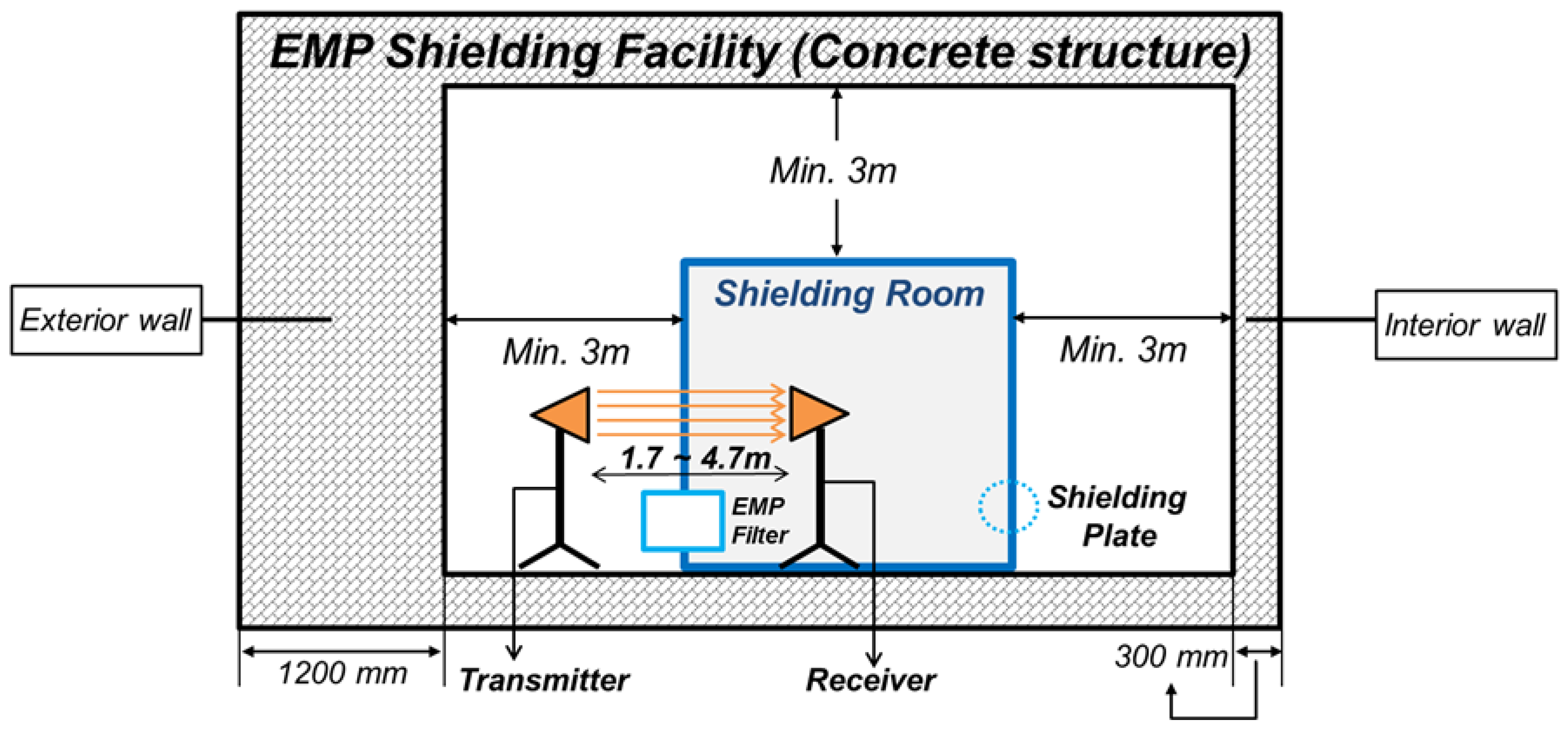
Figure 2.
Experimental process. (a) Substrate preparation; (b) application of ATMS; (c) specimen after ATMS (Zn-Al coating); (d) specimen after ATMS (Cu coating); (e) calibration work; (f) gasket installation; (g) EMP shielding wall (outside); (h) EMP shielding wall (inside); and (i) SE test.
Figure 2.
Experimental process. (a) Substrate preparation; (b) application of ATMS; (c) specimen after ATMS (Zn-Al coating); (d) specimen after ATMS (Cu coating); (e) calibration work; (f) gasket installation; (g) EMP shielding wall (outside); (h) EMP shielding wall (inside); and (i) SE test.
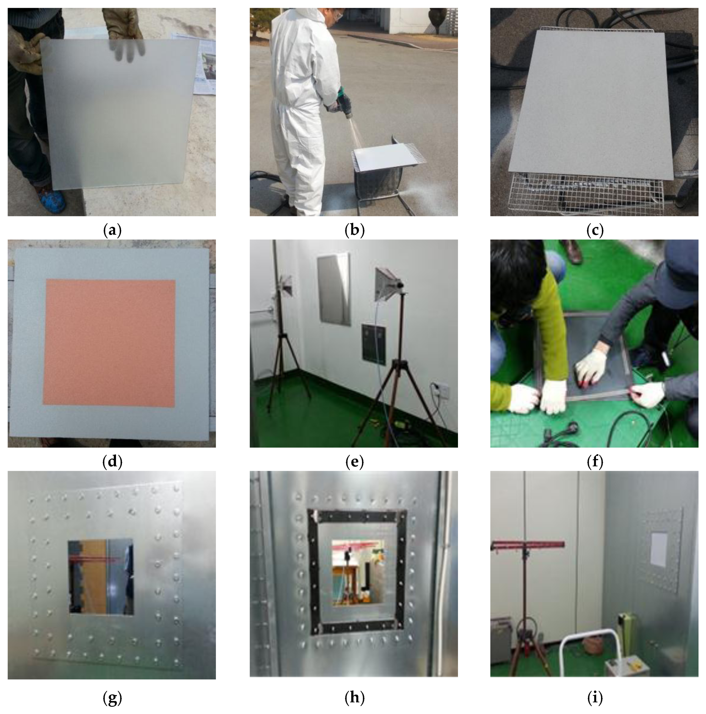
Figure 3.
SE test results between Plate-Fe and Plate-Cu.
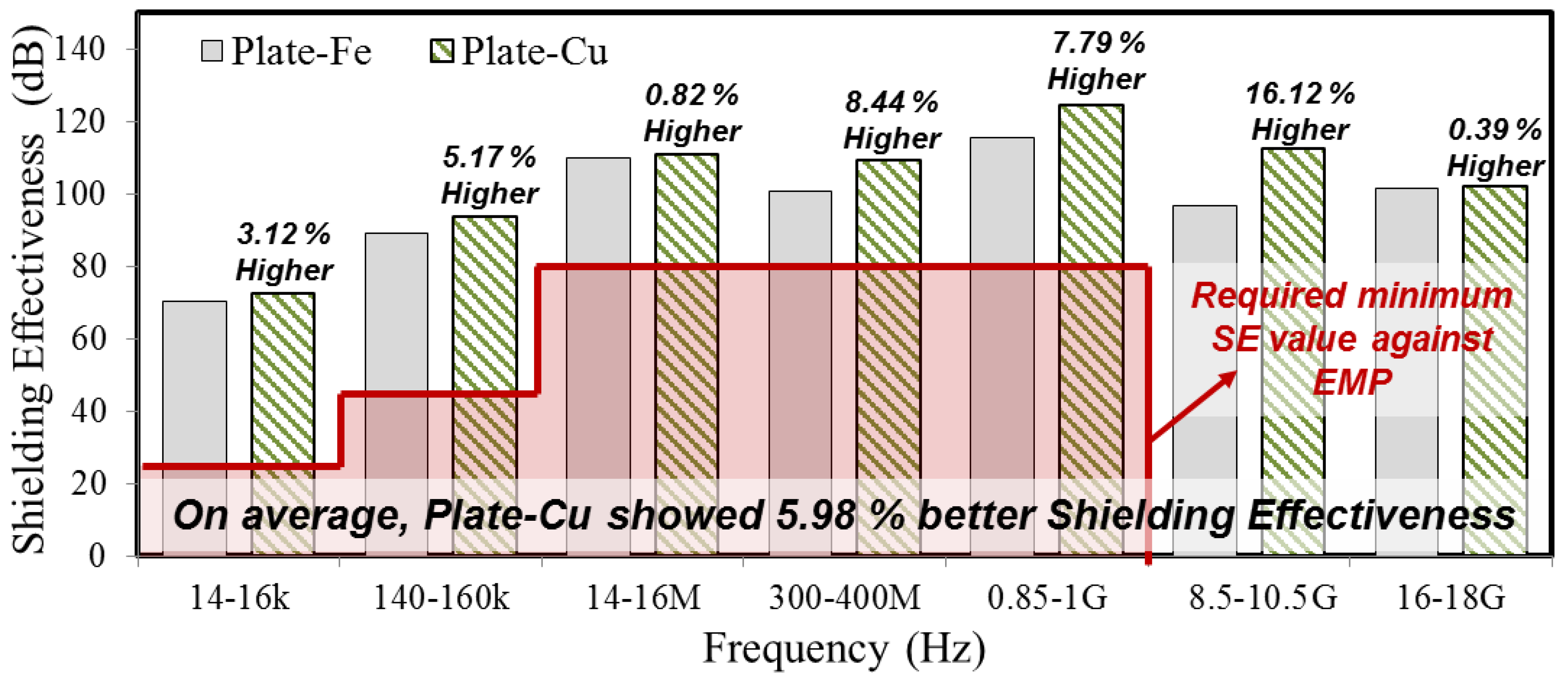
Figure 4.
SE test result of ATMS coatings by Zn-Al in regards to thickness.
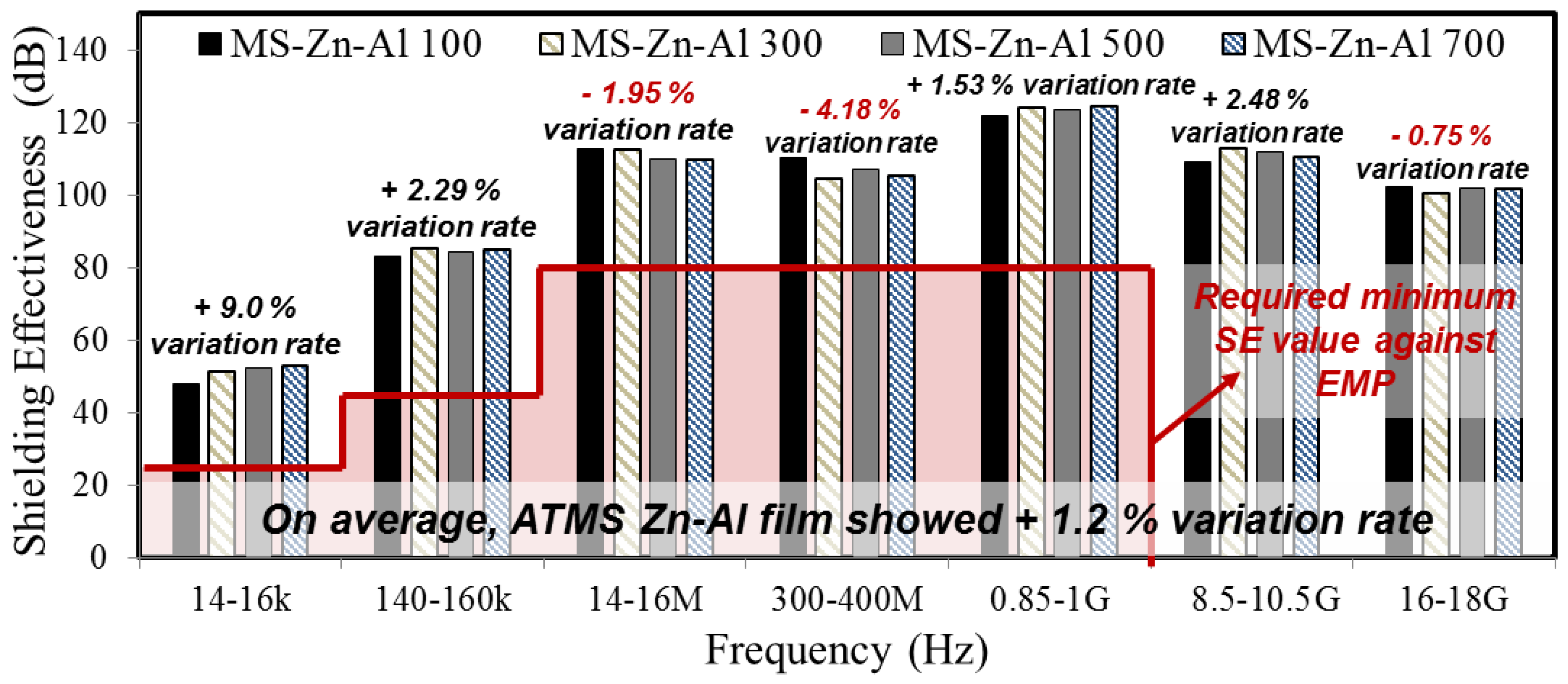
Figure 5.
SE test result of ATMS coatings by Cu in regards to thickness.
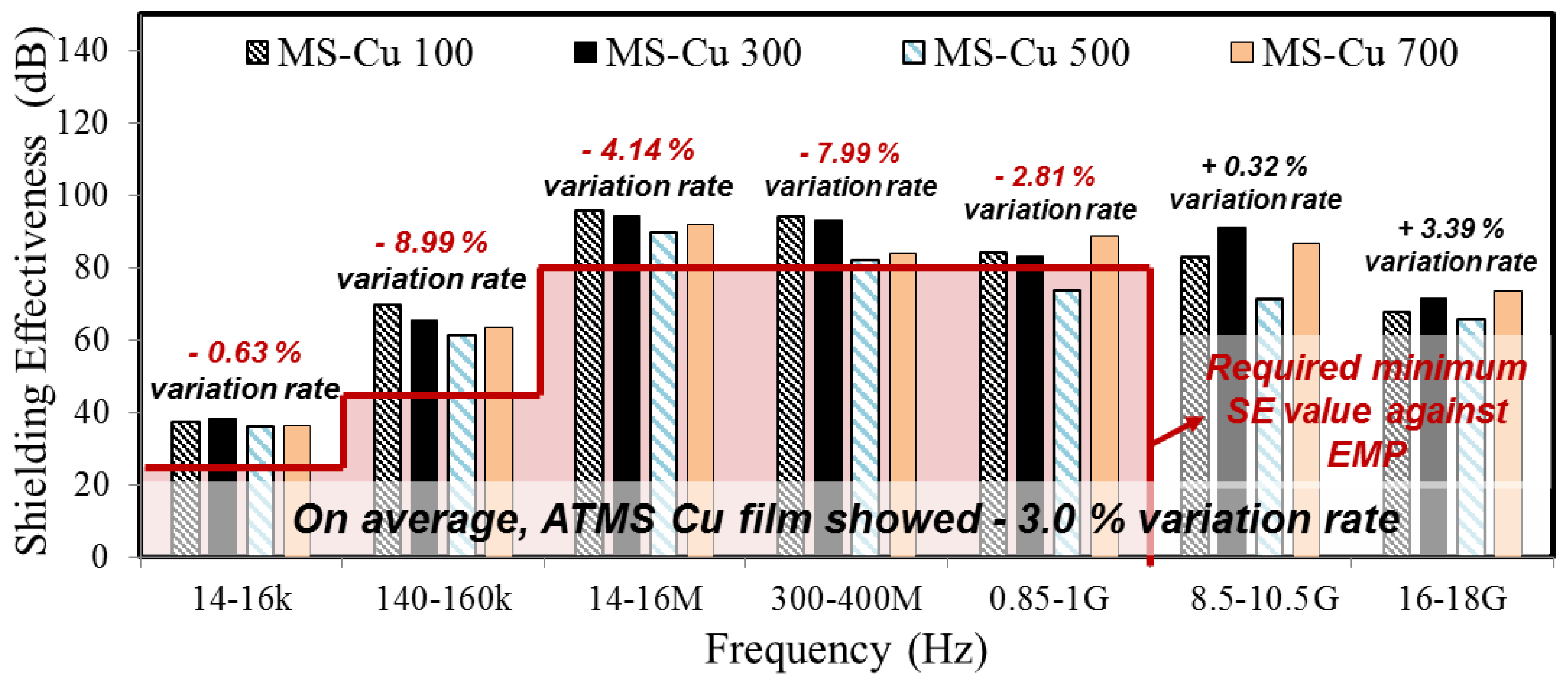
Figure 6.
SE test result between MS-Zn-Al 100 and MS-Cu 100.
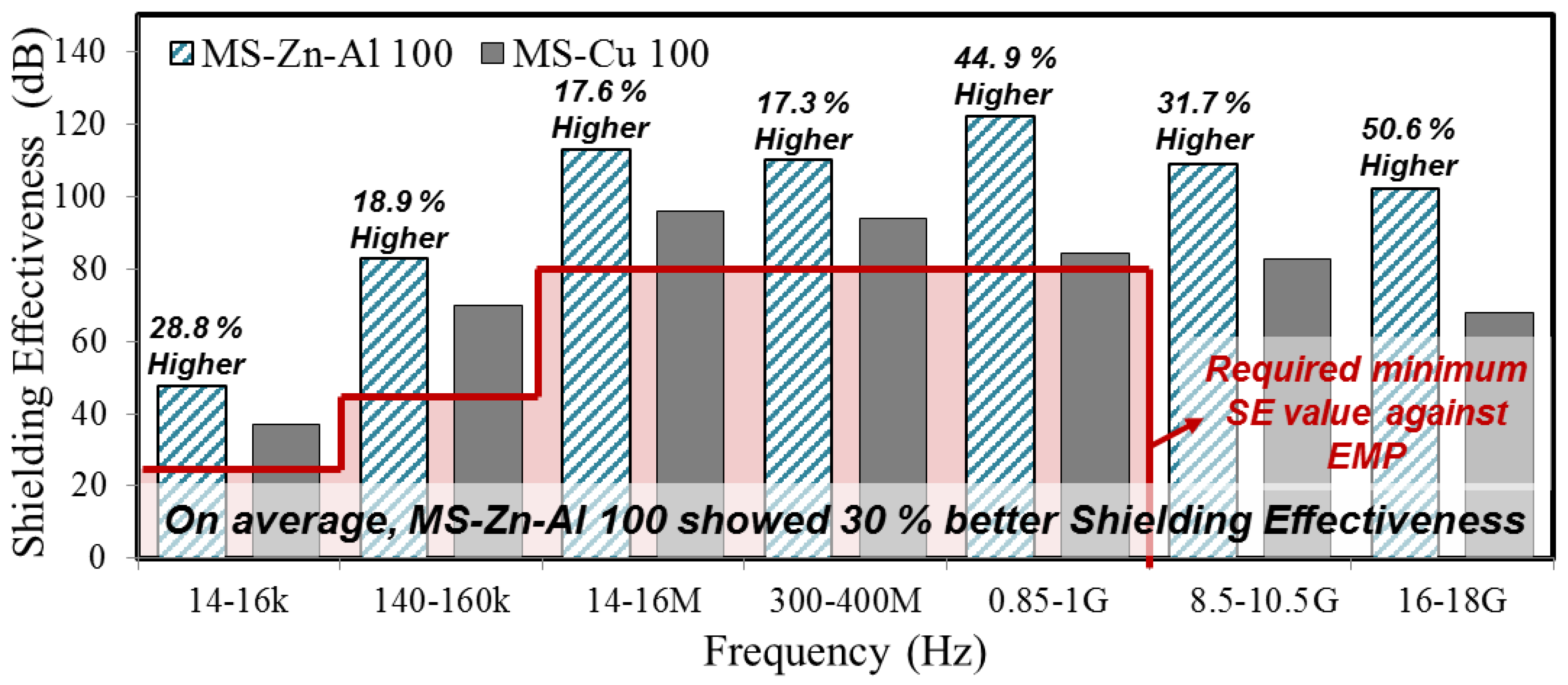
Figure 7.
SEM image of the specimen surface of (a) MS-Zn-Al 100 and (b) MS-Cu 100.

Figure 8.
SE test result between metal plate and ATMS coating by Cu.
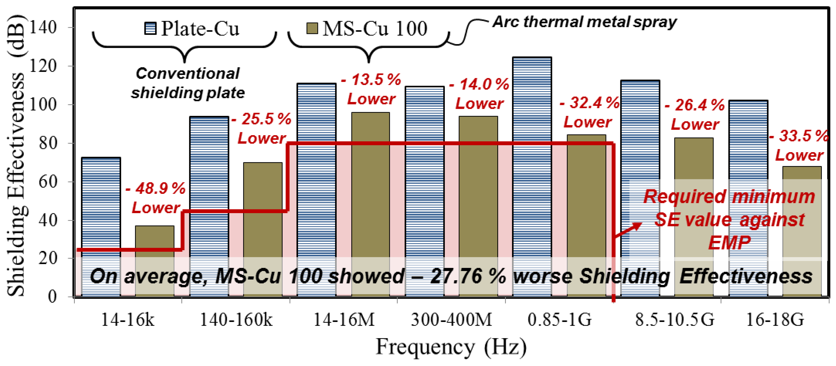
Figure 9.
SE test result between metal plate and ATMS coating by Zn-Al.

Table 1.
Experimental variables for the evaluation of the shielding effectiveness (SE) test against EMP.
Table 1.
Experimental variables for the evaluation of the shielding effectiveness (SE) test against EMP.
| Experimental Variables | Experimental Parameters |
|---|---|
| EMP Shielding method | Conventional shielding plate |
| Arc thermal metal spray | |
| EMP Shielding material | Fe |
| Cu | |
| Zn-Al | |
| Thickness of ATMS coating | 100 μm |
| 300 μm | |
| 500 μm | |
| 700 μm |
Table 2.
List of specimens for the SE test.
| No. | Specimens | Shielding Material | Shielding Method | Coating Thickness (μm) |
|---|---|---|---|---|
| 1 | Tempered glass1 | - | - | - |
| 2 | Plate2-Fe | Fe (steel) | Metal plate | 3000 |
| 3 | Plate-Cu | Cu (copper) | 3000 | |
| 4 | MS3-Zn-Al 100 | Zn-Al4 (zinc and aluminum) | Arc thermal metal spraying method | 100 |
| 5 | MS-Zn-Al 300 | 300 | ||
| 6 | MS-Zn-Al 500 | 500 | ||
| 7 | MS-Zn-Al 700 | 700 | ||
| 8 | MS-Cu 100 | Cu | 100 | |
| 9 | MS-Cu 300 | 300 | ||
| 10 | MS-Cu 500 | 500 | ||
| 11 | MS-Cu 700 | 700 |
Tempered glass1: Substrate for application of ATMS method; Plate2: Conventional EMP shielding plate (metal plate); MS3: Specimens which Arc thermal metal spray is applied; Zn-Al4: Zn and Al wire is applied at the same volume ratio (50:50), respectively.
Table 3.
SE test results of specimens 1–3.
| Frequency (Hz) | Required Minimum SE (dB) | Shielding Effectiveness (dB) | ||
|---|---|---|---|---|
| Tempered Glass | Plate-Fe | Plate-Cu | ||
| 14–16 k | 23.5 | 0.4 | 70.4 | 72.6 |
| 140–160 k | 43.5 | 0.1 | 89.0 | 93.6 |
| 14–16 M | 80 | 1.5 | 109.9 | 110.8 |
| 300–400 M | 80 | 0.5 | 100.7 | 109.2 |
| 0.85–1 G | 80 | 1.5 | 115.6 | 124.6 |
| 8.5–10.5 G | - | 1.3 | 96.8 | 112.4 |
| 16–18 G | - | 1.1 | 101.5 | 101.9 |
| Average SE (dB) | 0.91 | 97.70 | 103.59 | |
Table 4.
SE test results of specimens 4–7.
| Frequency (Hz) | Required Minimum SE (dB) | Shielding Effectiveness (dB) | |||
|---|---|---|---|---|---|
| MS-Zn-Al 100 | MS-Zn-Al 300 | MS-Zn-Al 500 | MS-Zn-Al 700 | ||
| 14–16 k | 23.5 | 47.8 | 51.2 | 52.3 | 52.8 |
| 140–160 k | 43.5 | 82.9 | 85.4 | 84.2 | 84.8 |
| 14–16 M | 80 | 112.7 | 112.3 | 109.7 | 109.5 |
| 300–400 M | 80 | 110.1 | 104.4 | 107.0 | 105.1 |
| 0.85–1 G | 80 | 122.0 | 123.9 | 123.4 | 124.3 |
| 8.5–10.5 G | - | 108.9 | 112.8 | 111.7 | 110.3 |
| 16–18 G | - | 102.1 | 100.5 | 102.0 | 101.5 |
| Average SE (dB) | 98.07 | 98.64 | 98.61 | 98.33 | |
Table 5.
SE test results of specimens 8–11.
| Frequency (Hz) | Required Minimum SE (dB) | Shielding Effectiveness (dB) | |||
|---|---|---|---|---|---|
| MS-Cu 100 | MS-Cu 300 | MS-Cu 500 | MS-Cu 700 | ||
| 14–16 k | 23.5 | 37.1 | 38.2 | 36.0 | 36.4 |
| 140–160 k | 43.5 | 69.7 | 65.4 | 61.4 | 63.5 |
| 14–16 M | 80 | 95.8 | 94.1 | 89.6 | 91.8 |
| 300–400 M | 80 | 93.9 | 93.2 | 82.1 | 83.9 |
| 0.85–1 G | 80 | 84.2 | 83.0 | 73.7 | 88.8 |
| 8.5–10.5 G | - | 82.7 | 91.2 | 71.2 | 86.5 |
| 16–18 G | - | 67.8 | 71.3 | 65.5 | 73.5 |
| Average SE (dB) | 75.89 | 76.63 | 68.50 | 74.91 | |
© 2017 by the authors. Licensee MDPI, Basel, Switzerland. This article is an open access article distributed under the terms and conditions of the Creative Commons Attribution (CC BY) license (http://creativecommons.org/licenses/by/4.0/).
Share and Cite
MDPI and ACS Style
Lee, H.-S.; Choe, H.-B.; Baek, I.-Y.; Singh, J.K.; Ismail, M.A. Study on the Shielding Effectiveness of an Arc Thermal Metal Spraying Method against an Electromagnetic Pulse. Materials 2017, 10, 1155. https://doi.org/10.3390/ma10101155
AMA Style
Lee H-S, Choe H-B, Baek I-Y, Singh JK, Ismail MA. Study on the Shielding Effectiveness of an Arc Thermal Metal Spraying Method against an Electromagnetic Pulse. Materials. 2017; 10(10):1155. https://doi.org/10.3390/ma10101155
Chicago/Turabian StyleLee, Han-Seung, Hong-Bok Choe, In-Young Baek, Jitendra Kumar Singh, and Mohamed A. Ismail. 2017. "Study on the Shielding Effectiveness of an Arc Thermal Metal Spraying Method against an Electromagnetic Pulse" Materials 10, no. 10: 1155. https://doi.org/10.3390/ma10101155
Note that from the first issue of 2016, this journal uses article numbers instead of page numbers. See further details here.